WO2024257624A1 - 通信装置、基地局、制御方法、プログラム - Google Patents
通信装置、基地局、制御方法、プログラム Download PDFInfo
- Publication number
- WO2024257624A1 WO2024257624A1 PCT/JP2024/019965 JP2024019965W WO2024257624A1 WO 2024257624 A1 WO2024257624 A1 WO 2024257624A1 JP 2024019965 W JP2024019965 W JP 2024019965W WO 2024257624 A1 WO2024257624 A1 WO 2024257624A1
- Authority
- WO
- WIPO (PCT)
- Prior art keywords
- srap
- stop
- relay
- pdu
- communication
- Prior art date
- Legal status (The legal status is an assumption and is not a legal conclusion. Google has not performed a legal analysis and makes no representation as to the accuracy of the status listed.)
- Ceased
Links
Images





Classifications
-
- H—ELECTRICITY
- H04—ELECTRIC COMMUNICATION TECHNIQUE
- H04W—WIRELESS COMMUNICATION NETWORKS
- H04W52/00—Power management, e.g. Transmission Power Control [TPC] or power classes
- H04W52/02—Power saving arrangements
- H04W52/0209—Power saving arrangements in terminal devices
- H04W52/0261—Power saving arrangements in terminal devices managing power supply demand, e.g. depending on battery level
-
- H—ELECTRICITY
- H04—ELECTRIC COMMUNICATION TECHNIQUE
- H04W—WIRELESS COMMUNICATION NETWORKS
- H04W16/00—Network planning, e.g. coverage or traffic planning tools; Network deployment, e.g. resource partitioning or cells structures
- H04W16/24—Cell structures
- H04W16/26—Cell enhancers or enhancement, e.g. for tunnels, building shadow
-
- H—ELECTRICITY
- H04—ELECTRIC COMMUNICATION TECHNIQUE
- H04W—WIRELESS COMMUNICATION NETWORKS
- H04W52/00—Power management, e.g. Transmission Power Control [TPC] or power classes
- H04W52/02—Power saving arrangements
-
- H—ELECTRICITY
- H04—ELECTRIC COMMUNICATION TECHNIQUE
- H04W—WIRELESS COMMUNICATION NETWORKS
- H04W76/00—Connection management
- H04W76/30—Connection release
-
- H—ELECTRICITY
- H04—ELECTRIC COMMUNICATION TECHNIQUE
- H04W—WIRELESS COMMUNICATION NETWORKS
- H04W88/00—Devices specially adapted for wireless communication networks, e.g. terminals, base stations or access point devices
- H04W88/02—Terminal devices
- H04W88/04—Terminal devices adapted for relaying to or from another terminal or user
-
- H—ELECTRICITY
- H04—ELECTRIC COMMUNICATION TECHNIQUE
- H04W—WIRELESS COMMUNICATION NETWORKS
- H04W92/00—Interfaces specially adapted for wireless communication networks
- H04W92/16—Interfaces between hierarchically similar devices
- H04W92/18—Interfaces between hierarchically similar devices between terminal devices
Definitions
- This disclosure relates to a communication device, a base station, a control method, and a program.
- 3GPP 3rd Generation Partnership Project
- LTE Long Term Evolution
- NR New Radio
- 3GPP registered trademark
- 3GPP is currently developing specifications to expand the communication range of Sidelink by using a Sidelink relay function that relays Sidelink communication via a relay device (relay UE).
- a means is specified for a communication terminal (remote UE) that has the function of connecting to a base station through the Sidelink relay function to switch from an indirect path.
- a means is specified for switching from communication connecting to a base station via a relay UE (indirect path) to direct communication with the base station (direct path) without disconnecting the service
- a means is specified for switching from a direct path to an indirect path without disconnecting the service.
- Patent document 1 proposes a means for a remote UE to switch from an indirect path to a direct path without disconnecting the service.
- the decision to switch paths is made mainly based on the signal strength between the remote UE and relay UE and between the remote UE and the base station, without taking into consideration the circumstances within the relay UE.
- circumstances within the relay UE include the remaining battery charge of the relay UE and a fail-soft function due to the loss of some processes.
- the relay function cannot continue due to circumstances within the relay UE, there is no mechanism to inform the base station of this. In this case, if the relay function of the relay UE suddenly stops, a sequence of reconnection to the base station will be run, which may reduce service continuity.
- the present invention has been made in consideration of at least one of the above problems.
- One aspect of the present invention aims to provide a mechanism that enables the base station to use information regarding the suspension of the relay function of a relay UE.
- a base station includes a communication means for communicating with a remote UE via a relay UE (User Equipment);
- the relay UE is characterized in comprising: a receiving means for receiving an SRAP control PDU, which is a Sidelink Adaptation Protocol (SRAP) PDU, from the relay UE; and a control means for executing communication control related to the communication means, based on the stop-related information, when the SRAP control PDU, in which stop-related information related to stop of relaying via the relay UE is stored, is received by the receiving means.
- SRAP Sidelink Adaptation Protocol
- FIG. 1 is a diagram illustrating a configuration of a communication device according to an embodiment of the present invention.
- 2 is a block diagram showing an example of a functional configuration of a base station according to the present embodiment.
- FIG. FIG. 2 is a block diagram showing an example of a functional configuration of a relay UE in the present embodiment.
- FIG. 11 is a diagram illustrating an example of a configuration of a relay function continuance disable notification according to the first embodiment.
- FIG. 11 is a diagram illustrating an example of a configuration of a relay function continuance disable notification according to the first embodiment.
- 4 is a flowchart between communication devices according to the first embodiment.
- FIG. 11 is a diagram illustrating an example of the configuration of a relay function continuance disable notification in the second embodiment.
- 10 is a flowchart between communication devices according to the second embodiment.
- First Embodiment 1 is a diagram showing an example of the configuration of a system according to this embodiment.
- UE A (101) and UE B (102) are within a communication area 104 of a base station 103.
- the UE User Equipment
- the UE is assumed to be a terminal compatible with Sidelink relay communication.
- the UE is assumed to be a smartphone or the like, but is not limited to this.
- the UE may be a communication terminal such as a tablet terminal or a PC, a wearable terminal such as a smart watch or a head-mounted display, or a car navigation device installed in an automobile.
- UE A (101) operates as a remote UE and communicates with base station 103 using Sidelink relay communication.
- UE B (102) operates as a relay UE and relays communication between UE A (101) and base station 103 using the Sidelink relay function.
- UE A (101) is sending and receiving data to and from the base station over an indirect path with UE B (102).
- FIG. 2 is a block diagram showing an example of the functional configuration of the base station 103 in this embodiment.
- the base station 103 includes a control unit 201, a memory unit 202, a UE management unit 203, a path switching processing unit 204, an SRAP PDU generation processing unit 205, an SRAP PDU analysis processing unit 206, and a wireless communication unit 207.
- the control unit 201 controls the operation of the base station 103.
- the control unit 201 is composed of one or more processors such as a CPU or MPU, and controls the entire communication device by executing a control program read into the RAM, which is the storage unit 202.
- processors such as a CPU or MPU
- the control unit 201 controls the entire communication device by executing a control program read into the RAM, which is the storage unit 202.
- ASIC is an abbreviation for Application Specific Integrated Circuit
- FPGA is an abbreviation for Field Programmable Gate Array.
- the processes described in the flowcharts below can be realized by using hardware circuits in cooperation with processors such as a CPU or MPU.
- the memory unit 202 stores information used by the control unit 201 for control and information related to communication.
- the memory unit 202 may include a main memory unit and an auxiliary memory unit.
- the main memory unit may be, for example, a ROM (Read Only Memory) or a RAM (Random Access Memory).
- the main memory unit may store or temporarily store programs and data such as the OS (Operating System) which is the basic software executed by the control unit 201 and application software.
- the auxiliary memory unit may be, for example, a HDD (Hard Disk Drive) or an SSD (Solid State Drive), and may store data related to application software.
- a control program stored in a non-volatile memory area is expanded in a RAM (Random Access Memory) and executed by a processor constituting the control unit 201.
- the control unit 201 and the storage unit 202 may function as a so-called computer.
- the storage unit 202 may include a recording medium that stores a specific program.
- the program stored in this recording medium may be installed via a drive device or the like, and the installed specific program may be executable by the control unit 201.
- the recording medium may be of various types.
- the recording medium may be a recording medium that records information optically, electrically, or magnetically, such as a CD (Compact Disc)-ROM, a flexible disk, or a magneto-optical disk.
- the recording medium may also be a semiconductor memory that records information electrically, such as a ROM or a flash memory.
- the recording medium does not include a carrier wave.
- the UE management unit 203 manages UE information within the base station area.
- the UE management unit 203 manages UE information including the IDs of subordinate UEs and measurement results reported from subordinate UEs (such as the signal strength of the Uu link, which will be described later).
- the path switching processing unit 204 determines whether to connect the UE under its management via an indirect path or a direct path based on the UE information managed by the UE management unit 203.
- the SRAP PDU generation processing unit 205 generates a message used to instruct path switching.
- the SRAP PDU generation processing unit 205 generates a PDU (SRAP PDU) used in the Sidelink Adaptation Protocol (SRAP).
- SRAP is a protocol used in the NR (New Radio) Sidelink relay function.
- the SRAP PDU analysis processing unit 206 analyzes the SRAP PDU received from a subordinate relay UE (hereinafter also referred to as a "subordinate relay UE").
- Functions corresponding to the UE management unit 203, the path switching processing unit 204 and/or the SRAP PDU generation processing unit 205 may be realized as software modules implemented by the control unit 201.
- the wireless communication unit 207 transmits and receives information via wireless communication with the subordinate UE. For example, the wireless communication unit 207 transmits messages generated by the SRAP PDU generation processing unit 205, receives SRAP PDUs from the subordinate UE, and receives other necessary wireless signals.
- FIG. 3 is a block diagram showing an example of the functional configuration of a relay UE (102) in this embodiment.
- the relay UE (102) includes a control unit 301, a memory unit 302, a signal strength measurement unit 303, a Sidelink Relay processing unit 304, an SRAP PDU generation processing unit 305, an SRAP PDU analysis processing unit 306, and a wireless communication unit 307.
- the control unit 301 controls the operation of the relay UE (102).
- the control unit 301 is composed of one or more processors such as a CPU or MPU, and controls the entire communication device by executing a control program read into the RAM, which is the storage unit 302.
- processors such as a CPU or MPU
- the control unit 301 controls the entire communication device by executing a control program read into the RAM, which is the storage unit 302.
- each process performed by the control unit 301 which will be described in the flowcharts below, can also be realized using hardware circuits such as ASICs or FPGAs.
- the processes described in the flowcharts below can also be realized by having the hardware circuits work in cooperation with a processor such as a CPU or MPU.
- the memory unit 302 stores information used by the control unit 301 for control and information related to communication.
- the signal strength measurement unit 303 measures the "signal strength between remote UEs (PC5 link)" and the “signal strength between base stations (Uu link)" as seen from the relay UE (102).
- the Sidelink Relay processing unit 304 establishes a Sidelink connection with the remote UE. This enables the Sidelink Relay processing unit 304 to relay communication between the remote UE and the base station 103 via the NR Sidelink relay function of the relay UE (i.e., an indirect path). Note that, below, the NR Sidelink relay function is also simply referred to as the Sidelink relay function.
- the SRAP PDU generation processing unit 305 is an SRAP PDU generation unit, similar to the SRAP PDU generation processing unit 205 of the base station 103 described above.
- the SRAP PDU generation processing unit 305 when the relay UE determines that its NR Sidelink relay function cannot be continued, the SRAP PDU generation processing unit 305 generates a PDU (an example of stop-related information) for notifying the base station 103 that the relay function cannot be continued. Details of the PDU for notifying the base station 103 that the relay function cannot be continued will be described later with reference to FIG. 4.
- the SRAP PDU analysis processing unit 306 analyzes the SRAP PDU received from the remote UE and the base station 103.
- the wireless communication unit 307 transmits and receives information via wireless communication with the remote UE and base station 103.
- the wireless communication unit 307 performs transmission processing of the SRAP PDU generated by the SRAP PDU generation processing unit 305, reception processing of the SRAP PDU from the remote UE and base station 103, and reception processing of other necessary wireless communication.
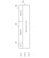
- Figure 4 shows an example of the structure of a PDU that indicates that the relay function cannot continue.
- a bit of the D/C field 401 of a PDU in an SRAP When a bit of the D/C field 401 of a PDU in an SRAP is set to 0, this indicates that the PDU is data (i.e., an SRAP DATA PDU). When a bit of the D/C field 401 of a PDU in an SRAP is set to 1, this indicates that the PDU is a control message (i.e., an SRAP Control PDU). In a PDU indicating that the relay function cannot be continued, a value of 1 is set in the D/C field 401. In this embodiment, when the D/C field 401 is set to a value indicating an SRAP Control PDU, the PDU type field 402 is configured to have 4 bits, and the Reserved field 403 is configured to have 3 bits. When the D/C field 401 is set to a value indicating an SRAP Control PDU, the fields following the Reserved field 403 are configured as optional fields.
- the PDU type field 402 indicates whether the relay function cannot be continued if the PDU is an SRAP Control PDU. In this embodiment, if the PDU type field 402 has a value of 0000, it indicates that the relay function cannot be continued. Note that the value of 0000 is only an example, and any other value may be used as long as it does not overlap with values of other PDU types.
- the SRAP Control PDU including a value corresponding to "relay function cannot be continued” is illustrated as an example of the stop-related information, but is not limited to this. Anything indicating that relaying cannot be continued/operation as a relay will not be continued may be used.
- a value corresponding to a relay RLF (Radio Link Failure) indicating that a problem has occurred with the radio link for relaying may be used as the stop-related information for the SRAP Control PDU.
- the stop-related information of this embodiment can be modified in any way as long as it is information that causes an action such as informing the base station that communication may be interrupted.
- the above specific example is merely one example of the stop-related information, and it is noted for the sake of clarity that the actual name and the specific format for notifying the information are not limited to the above specific example.
- the reserved field 403 is an unused field.
- Option field 1 is a field for storing additional information, and uses the fields from the second octet onwards of the PDU.
- the remaining time that the relay UE can continue the relay function is stored as additional information. Note that this is just one example, and other appropriate configurations may be used. For example, in addition to the remaining relay function continuation time mentioned above, a field may be added that indicates the reason why the relay UE cannot continue the relay function.
- FIG. 5 shows an example of the configuration of a PDU indicating that the relay function cannot be continued, which adds the reason why the relay UE cannot continue the relay function.
- option field 2 (indicated by reference numeral 504) is added to the format shown in FIG. 4.
- Option field 2 stores a value indicating the reason why the relay function cannot be continued. The reason why the relay function cannot be continued will be described later.
- FIG. 6 is an example of a flowchart in this embodiment showing a notification by a relay UE that the relay function cannot be continued, and a decision by base station 103, upon receipt of the notification, to switch from an indirect path to a direct path.
- the processing shown in the flowchart can be realized in base station 103 by control unit 201 executing a control program stored in storage unit 202, thereby calculating and processing information and controlling each piece of hardware.
- control unit 301 executing a control program stored in storage unit 302, thereby calculating and processing information and controlling each piece of hardware.
- UE B (102) which is a relay UE, uses the Sidelink Relay processing unit 304 to perform relaying. That is, UE B (102) relays communication of user data (such as streaming data) between UE A (101), which is a remote UE, and the base station 103 via an indirect path (S601).
- user data such as streaming data
- the control unit 301 of the UE B (102) judges whether or not the relay function of the own terminal cannot be continued (S602). Then, when the control unit 301 of the UE B (102) judges that the relay function of the own terminal cannot be continued, it notifies the Sidelink Relay processing unit 304 that the relay function cannot be continued.
- the control unit 301 may judge that the relay function of the own terminal cannot be continued when a predetermined condition is satisfied.
- the predetermined condition may be a condition related to the state (device state or communication state) of the relay UE. For example, when any one of the following conditions (1) to (7) is satisfied, it may be judged that the relay function of the own terminal cannot be continued.
- Condition (1) The remaining battery power of the device falls below a threshold.
- Condition (2) A hardware failure is detected.
- Condition (3) Some processes (for example, processes operating to realize the signal strength measurement unit 303) are lost.
- Condition (4) When the user or a user application executes control to turn off the NR Sidelink Relay function.
- control unit 301 may determine that it is impossible to continue the relay function of the own terminal when any combination of two or more of the above conditions (1) to (7) is satisfied.
- condition (1) and the like may be determined in a manner that includes prediction. For example, regarding condition (1), it may be determined that condition (1) is not satisfied when the battery remaining amount of the own terminal is below a threshold but is currently being charged or is scheduled to be charged in a short time. Furthermore, regarding condition (1), the battery remaining amount of the own terminal may only relate to the battery remaining amount available for communication when the battery is also being used for purposes other than communication (e.g., for transportation).
- condition (8) In another embodiment, in addition to the above conditions (1) to (7), the following condition (8) may be determined.
- Condition (8) The temperature of the terminal (your device) exceeds the upper limit temperature.
- the Sidelink Relay processing unit 304 Upon receiving the notification from the control unit 301, the Sidelink Relay processing unit 304 creates an SRAP control PDU indicating that the relay function cannot be continued through the SRAP PDU generation processing unit 305 (S603).
- the SRAP control PDU indicating that the relay function cannot be continued may be referred to as a relay function continuation impossible notification.
- the SRAP PDU generation processing unit 305 stores the time until the relay function is stopped, calculated by the control unit 301, in the option field 1 (404).
- the option field is 2 bytes and stores 0 to 65535. The unit is seconds, and if the calculation is impossible (N/A), 0 is stored (S604).
- an option field 2 504 may be added and values corresponding to the above-mentioned conditions (1) to (8) may be stored.
- the following values can be set.
- the base station 103 side can grasp the reason for stopping the relay function in the relay UE. 0 Low battery (set when condition (1) is met) 1. Failure (hardware cause) (set when condition (2) is met) 2. Fault (software cause) (set when condition (3) is met) 3. Sidelink relay function off (set when condition (4) is met) 4. Power off or power reset (set if condition (5) is met) 5. PC5 link signal strength degraded (set if condition (6) is met) 6. Uu Link Signal Strength Degradation (set if condition (7) is met) 7 Terminal temperature rise (set when condition (8) is met)
- the Sidelink Relay processing unit 304 sends a notification to the base station 103 via the wireless communication unit 307 that the relay function cannot be continued (S605). If the time until the relay function is stopped calculated in S604 has elapsed, the control unit 301 stops the function of the Sidelink Relay processing unit 304. If the calculation is impossible, the function of the Sidelink Relay processing unit 304 is stopped when the time set as the initial value (e.g., 60 seconds) has elapsed (S606). Note that in a modified example, the function of the Sidelink Relay processing unit 304 may be stopped before the specified time has elapsed.
- the SRAP PDU analysis processing unit 206 analyzes the contents of the received SRAP PDU (S607).
- the analysis determines whether the D/C field 401 is a value indicating "SRAP Control PDU” and whether the PDU type field 402 is a value indicating "relay function cannot be continued” (S608). Then, if the D/C field 401 is a value indicating "SRAP Control PDU” and the PDU type field 402 is a value indicating "relay function cannot be continued” (i.e., the above-mentioned "relay function cannot be continued notification"), proceed to S609. In S609, the SRAP PDU analysis processing unit 206 determines that the SRAP PDU is a notification that the relay function cannot be continued.
- the SRAP PDU analysis processing unit 206 interprets the value stored in the option field 1 (404) as the time until the relay function is stopped and obtains the value. Based on the result of the analysis by the SRAP PDU analysis processing unit 206, the control unit 201 determines that it is difficult for UE B (102) to continue the relay function. In this case, the control unit 201 requests the path switching processing unit 204 to switch the path of UE A (101) within the time until the relay function is stopped (immediately if N/A). The path switching processing unit 204 switches UE A (101) from an indirect path to a direct path. If the received SRAP PDU is not a notification that the relay function cannot be continued, it performs processing corresponding to other SRAP PDUs (S610).
- the above flow allows UE B (102) and base station 103 to switch from an indirect path to a direct path in UE A (101) without interrupting the service when UE B (102) is unable to continue relaying.
- a mechanism can be provided that allows the base station 103 to obtain information regarding the suspension of the relay function of the relay UE (102) (notification that the relay function cannot be continued).
- the base station 103 can switch from an indirect path to a direct path in UE A (101) while maintaining the service in UE A (101).
- the relay UE (102) can include time information until the relay function is stopped in the notification of the inability to continue the relay function.
- the base station 103 can realize the switching from the indirect path to the direct path in UE A (101) at an appropriate timing based on such time information.
- the base station 103 can perform path switching for the remote UE without disconnecting the service when the NR Sidelink Relay function in the relay UE cannot be continued.
- the NR Sidelink Relay function of the relay UE is interrupted. For example, when a program that occupies the CPU usage rate or network bandwidth is executed in the relay UE, the NR Sidelink Relay function becomes unusable until the program is completed. Such a program is, for example, a throughput measurement application, but is not limited to this.
- the NR Sidelink relay function is suspended and stopped. Specifically, when a relay UE suspends its own NR Sidelink relay function, the SRAP PDU generation processing unit 305 generates a PDU for notifying the base station of the suspension of the relay function.
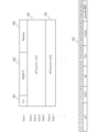
- An example of the configuration of a PDU indicating suspension of the relay function is shown in FIG. 7.
- the D/C field 401 has a value of 1, which indicates an SRAP Control PDU, followed by a 4-bit PDU type field 402 and a 3-bit Reserved field 403.
- the configuration followed by an options field is the same as in Figures 4 and 5.
- the PDU type field 402 has a value of 0001, it indicates "relay function interruption.”
- This SRAP Control PDU is hereafter referred to as the "relay function interruption notification.”
- the relay function interruption notification sets option field 1 704 to 4 bytes and option field 2 705 to 2 bytes.
- Option field 1 704 stores the planned time for relay interruption.
- the values that can be set in the 4 bytes are as follows: the 0th to 6th MSB bits represent the year, with 2023 being 0 and up to 127 (2150) being able to be stored.
- the following 7th to 10th bits represent the month, and may be able to store values 1 to 12.
- the 11th to 15th bits represent the day, and may be able to store values 1 to 31.
- the 16th to 20th bits represent the hour, and may be able to store values 0-23.
- the 21st to 26th bits represent the minutes, and may be able to store values 0-59.
- the 27th to 31st bits represent the seconds, and may be able to specify values 0-29 in 2-second increments.
- Option field 2 705 stores the time it takes for the relay function to be restored after an interruption. In this embodiment, this can be set to 1 to 65535 seconds.
- FIG. 8 is an example of a flowchart showing a process in this embodiment in which a relay UE notifies the base station that it has suspended its relay function and the base station determines whether to switch from an indirect path to a direct path after receiving the notification.
- UE B (102) which is a relay UE, performs relaying using the Sidelink Relay processing unit 304. That is, UE B (102) relays communication of user data (such as streaming data) between UE A (101), which is a remote UE, and the base station 103 via an indirect path (S801).
- user data such as streaming data
- the control unit 301 of UE B (102) determines whether or not it is necessary to interrupt the relay function of its own terminal (S802). If it is determined that it is necessary to interrupt the relay function of its own terminal, it proceeds to the processing of S803 and subsequent steps to notify the Sidelink Relay processing unit 304 of the interruption of the relay function.
- the Sidelink Relay Processing Unit 304 receives the notification from the Control Unit 301 and creates a PDU indicating the interruption of the relay function (hereinafter referred to as a relay function interruption notification) through the SRAP PDU Generation Processing Unit 305 (S803).
- the SRAP PDU Generation Processing Unit 305 stores the time until the relay function interruption calculated by the Control Unit 301 in option field 1 704.
- the SRAP PDU Generation Processing Unit 305 stores the recovery time of the relay function calculated by the Control Unit 301 in option field 2 705 (S804).
- the Sidelink Relay processing unit 304 sends a relay function interruption notification to the base station 103 via the wireless communication unit 307 (S805).
- the control unit 301 stops the function of the Sidelink Relay processing unit 304.
- the control unit 301 resumes the Sidelink Relay processing unit 304 (S806).
- the SRAP PDU analysis processing unit 206 analyzes the contents of the received SRAP PDU (S807).
- the SRAP PDU analysis processing unit 206 judges whether the D/C field 401 has a value indicating "SRAP Control PDU” and whether the PDU type field 402 indicates “relay function cannot be continued” (S808). If the D/C field 401 has a value indicating "SRAP Control PDU” and the PDU type field 402 indicates "relay function cannot be continued” (i.e., the above-mentioned "relay function cannot be continued notification"), the following occurs.
- the SRAP PDU analysis processing unit 206 judges that the SRAP PDU is a relay function cannot be continued notification ( Figures 4 and 5), and proceeds to S609 according to STEP 1 of Figure 6 in the first embodiment (S809).
- the SRAP PDU analysis processing unit 206 determines that the SRAP PDU is a relay function interruption notification, interprets the value stored in option field 1 704 as the time until the relay function is interrupted, and obtains that value. It also interprets the value stored in option field 2 705 as the time from interruption until recovery of the relay function, and obtains that value.
- the control unit 201 Based on the analysis results of the SRAP PDU analysis processing unit 206, the control unit 201 recognizes that UE B (102) will suspend the relay function, and requests the path switching processing unit 204 to switch the path of UE A (101) within the time until the relay function is suspended.
- the path switching processing unit 204 switches UE A (101) from an indirect path to a direct path (S811, S812). If the received SRAP PDU is not a relay function suspension notification, it performs processing corresponding to other SRAP PDUs (S813).
- the control unit 201 After the relay function recovery time of UE B (102) acquired in S810 has elapsed, the control unit 201 acquires the signal strength with UE A (101) switched in S812 and the signal strength with UE B (102) from the UE management unit 203 and compares them. If the signal strength with UE B (102) is greater than the signal strength with UE A, it determines to switch to the original indirect path (i.e., the system configuration shown in FIG. 1) and has the path switching processing unit 204 execute the path switching (S814, S815, S816).
- the above flow allows UE B (102) and base station 103 to switch UE A (101) from an indirect path to a direct path without interrupting the service when UE B (102) discontinues relaying.
- the base station 103 takes into consideration the possibility that both the relay function cannot be continued notification and the relay function interruption notification will be received.
- switching from an indirect path to a direct path is performed based on a notification that the relay function cannot be continued or a notification that the relay function is interrupted, but this is not limited to this.
- switching from an indirect path to another indirect path using another relay UE may be realized based on a notification that the relay function cannot be continued or a notification that the relay function is interrupted. For example, if the signal strength between UE A (101) and base station 103 is lower than the signal strength between UE A (101) and another UE (UE other than UE B (102)), switching to an indirect path via that other UE may be realized.
- a method may be used to notify the gNB that the relay function cannot be continued or interrupted by using the RRC connection between the base station and the relay UE.
Landscapes
- Engineering & Computer Science (AREA)
- Computer Networks & Wireless Communication (AREA)
- Signal Processing (AREA)
- Mobile Radio Communication Systems (AREA)
Abstract
Description
前記リレーUEから、Sidelink Adaptation Protocol(SRAP)のPDUである、SRAP control PDUを受信する受信手段と、前記リレーUEを介する中継の停止に関する停止関連情報が格納されたSRAP control PDUが前記受信手段により受信した場合に、前記停止関連情報に基づいて、前記通信手段に係る通信制御を実行する制御手段とを備えることを特徴とする。
図1は、本実施形態に係るシステムの構成例を示す図である。図1において、UE A(101)とUE B(102)は、基地局103の通信エリア104内にある。
条件(1) 自端末のバッテリ残量が閾値を下回った場合。
条件(2) ハードウェア故障を検出した場合。
条件(3) 一部のプロセス(例えば、信号強度測定部303を実現するために動作しているプロセス等)が消失した場合。
条件(4) ユーザ又はユーザーアプリケーションによるNR Sidelink Relay機能のオフ制御が実行された場合。
条件(5) ユーザによる電源オフもしくは電源リセット制御が実行された場合。
条件(6) PC5リンクの信号強度が閾値を下回った場合。
条件(7) Uuリンクの信号強度が閾値を下回った場合。
条件(8) 端末(自機)の温度が上限温度を上回った場合。
0 バッテリ残量低下(条件(1)が満たされた場合に設定する)
1 故障(ハードウェア要因)(条件(2)が満たされた場合に設定する)
2 故障(ソフトウェア要因)(条件(3)が満たされた場合に設定する)
3 サイドリンクリレー機能オフ(条件(4)が満たされた場合に設定する)
4 電源オフまたは電源リセット(条件(5)が満たされた場合に設定する)
5 PC5リンク信号強度低下(条件(6)が満たされた場合に設定する)
6 Uuリンク信号強度低下(条件(7)が満たされた場合に設定する)
7 端末温度上昇(条件(8)が満たされた場合に設定する)
第二の実施形態における通信装置の構成(図1)、通信装置の機能構成(図2、図3)は第一の実施形態と同様である。
Claims (23)
- 基地局とリモートUE(User Equipment)との間の通信を中継するSidelink中継手段と、
Sidelink Adaptation Protocol(SRAP)のPDU(Protocol Data Unit)である、SRAP control PDUを生成する生成手段と、
前記生成手段により生成される前記SRAP control PDUを送信する送信手段とを備え、
前記生成手段は、前記Sidelink中継手段による中継が行われている状況下で所定条件を満たした場合に、前記Sidelink中継手段による中継の停止に関する停止関連情報を前記SRAP control PDUに格納する、通信装置。 - 前記所定条件は、自装置の状態に関する、請求項1に記載の通信装置。
- 自装置に電力を供給するバッテリの残量を検出する第1検出手段を更に備え、
前記所定条件は、前記第1検出手段により検出される前記バッテリの残量が閾値を下回る場合に満たされる、請求項1又は2に記載の通信装置。 - 自装置における所定異常を検出する第2検出手段を更に備え、
前記所定条件は、前記第2検出手段により前記所定異常が検出される場合に満たされる、請求項1乃至3のいずれか1項に記載の通信装置。 - 前記所定異常は、自装置のハードウェアの故障、及び、自装置に実装のソフトウェアにおけるプロセスの消失、のうちの少なくともいずれか一方を含む、請求項4に記載の通信装置。
- 前記所定条件は、前記Sidelink中継手段に係る機能がオフされる場合に満たされる、請求項1乃至5のいずれか1項に記載の通信装置。
- 前記所定条件は、自装置の電源がオフ又はリセットされる場合に満たされる、請求項1乃至6のいずれか1項に記載の通信装置。
- 前記リモートUEから受信する信号の信号強度を測定する第1測定手段を更に備え、
前記所定条件は、前記信号強度が閾値を下回る場合に満たされる、請求項1乃至7のいずれか1項に記載の通信装置。 - 前記基地局から受信する信号の信号強度を測定する第2測定手段を更に備え、
前記所定条件は、前記信号強度が閾値を下回る場合に満たされる、請求項1乃至8のいずれか1項に記載の通信装置。 - 前記生成手段は、前記SRAP control PDUのD/C fieldに、「SRAP control PDU」を意味する値を格納する、請求項1乃至9のいずれか1項に記載の通信装置。
- 前記生成手段は、前記SRAP control PDUのPDU type fieldに、前記停止関連情報を格納する、請求項1乃至10のいずれか1項に記載の通信装置。
- 前記停止関連情報は、前記Sidelink中継手段に係る機能の停止を表す情報、前記停止までの時間を表す情報、前記停止の要因を表す情報、及び、前記停止後の再開までの時間を表す情報、のうちの少なくともいずれか1つを含む、請求項1乃至11のいずれか1項に記載の通信装置。
- リレーUE(User Equipment)を介してリモートUEと通信する通信手段と、
前記リレーUEから、Sidelink Adaptation Protocol(SRAP)のPDUである、SRAP control PDUを受信する受信手段と、
前記リレーUEを介する中継の停止に関する停止関連情報が格納されたSRAP control PDUを前記受信手段により受信した場合に、前記停止関連情報に基づいて、前記通信手段に係る通信制御を実行する制御手段とを備える、基地局。 - 前記制御手段は、前記SRAP control PDUのD/C fieldに、「SRAP control PDU」を意味する値が格納されている場合に、前記SRAP control PDUのPDU type fieldに格納されている前記停止関連情報に基づいて、前記通信制御を実行する、請求項13に記載の基地局。
- 前記通信制御は、前記停止関連情報に基づいて、前記リモートUEに対して、前記リレーUEを介する間接パスから、別のパスへの切替を指示することを含む、請求項13に記載の基地局。
- 前記停止関連情報は、前記リレーUEを介してリモートUEへ中継を行う機能の停止を表す情報、前記停止までの時間を表す情報、前記停止の要因を表す情報、及び、前記停止後の再開までの時間を表す情報、のうちの少なくともいずれか1つを含む、請求項15に記載の基地局。
- 前記通信制御は、前記停止までの時間を表す情報に基づいて、前記停止までの時間内に、前記切替を指示することを含む、請求項16に記載の基地局。
- 前記通信制御は、前記停止後の再開までの時間を表す情報に基づいて、切替後の前記別のパスから前記間接パスへの切替を指示することを含む、請求項16又は17に記載の基地局。
- 通信を制御する制御方法であって、
基地局とリモートUE(User Equipment)との間の通信を中継する中継工程と、
Sidelink Adaptation Protocol(SRAP)のPDUである、SRAP control PDUを生成する生成工程と、
前記生成工程により生成される前記SRAP control PDUを送信する送信工程とを有し、
前記生成工程は、前記中継工程による中継が行われている状況下で所定条件を満たした場合に、前記中継工程による中継の停止に関する停止関連情報を前記SRAP control PDUに格納することを含む、制御方法。 - コンピュータに、
基地局とリモートUE(User Equipment)との間の通信を中継する中継工程と、
Sidelink Adaptation Protocol(SRAP)のPDUである、SRAP control PDUを生成する生成工程と、
前記生成工程により生成される前記SRAP control PDUを送信する送信工程とを実行させ、
前記生成工程は、前記中継工程による中継が行われている状況下で所定条件を満たした場合に、前記中継工程による中継の停止に関する停止関連情報を前記SRAP control PDUに格納することを含む、プログラム。 - リレーUE(User Equipment)を介してリモートUEと通信する通信工程と、
前記リレーUEから、Sidelink Adaptation Protocol(SRAP)のPDUである、SRAP control PDUを受信する受信工程と、
前記リレーUEを介する中継の停止に関する停止関連情報が格納されたSRAP control PDUを前記受信工程により受信した場合に、前記停止関連情報に基づいて、前記通信工程に係る通信制御を実行する制御工程とを備える、制御方法。 - コンピュータに、
リレーUE(User Equipment)を介してリモートUEと通信する通信工程と、
前記リレーUEから、Sidelink Adaptation Protocol(SRAP)のPDUである、SRAP control PDUを受信する受信工程と、
前記リレーUEを介する中継の停止に関する停止関連情報が格納されたSRAP control PDUを前記受信工程により受信した場合に、前記停止関連情報に基づいて、前記通信工程に係る通信制御を実行する制御工程と、を実行させるプログラム。 - 基地局とリモートUE(User Equipment)との間の通信を中継するSidelink中継手段と、
前記Sidelink中継手段による中継が行われている状況下で所定条件を満たした場合に、前記Sidelink中継手段による中継の停止に関する停止関連情報を前記基地局に通知する通知手段と、
を有することを特徴とする通信装置。
Priority Applications (2)
| Application Number | Priority Date | Filing Date | Title |
|---|---|---|---|
| EP24823244.9A EP4730907A1 (en) | 2023-06-13 | 2024-05-31 | Communication device, base station, control method, and program |
| US19/415,495 US20260101197A1 (en) | 2023-06-13 | 2025-12-10 | Communication apparatus, base station, control method, and storage medium |
Applications Claiming Priority (2)
| Application Number | Priority Date | Filing Date | Title |
|---|---|---|---|
| JP2023-096727 | 2023-06-13 | ||
| JP2023096727A JP2024178533A (ja) | 2023-06-13 | 2023-06-13 | 通信装置、基地局、制御方法、プログラム |
Related Child Applications (1)
| Application Number | Title | Priority Date | Filing Date |
|---|---|---|---|
| US19/415,495 Continuation US20260101197A1 (en) | 2023-06-13 | 2025-12-10 | Communication apparatus, base station, control method, and storage medium |
Publications (1)
| Publication Number | Publication Date |
|---|---|
| WO2024257624A1 true WO2024257624A1 (ja) | 2024-12-19 |
Family
ID=93851894
Family Applications (1)
| Application Number | Title | Priority Date | Filing Date |
|---|---|---|---|
| PCT/JP2024/019965 Ceased WO2024257624A1 (ja) | 2023-06-13 | 2024-05-31 | 通信装置、基地局、制御方法、プログラム |
Country Status (4)
| Country | Link |
|---|---|
| US (1) | US20260101197A1 (ja) |
| EP (1) | EP4730907A1 (ja) |
| JP (1) | JP2024178533A (ja) |
| WO (1) | WO2024257624A1 (ja) |
Citations (5)
| Publication number | Priority date | Publication date | Assignee | Title |
|---|---|---|---|---|
| JPH0847046A (ja) * | 1994-07-29 | 1996-02-16 | Sharp Corp | デジタルコードレス電話機 |
| US20210007104A1 (en) * | 2019-07-02 | 2021-01-07 | Qualcomm Incorporated | Methods for power savings with millimeter wave relays |
| WO2022067651A1 (en) * | 2020-09-30 | 2022-04-07 | Lenovo (Beijing) Limited | Methods and apparatuses for a relay reselection and data transmission handling procedure in a ue-to-network relay scenario |
| US20220377822A1 (en) | 2020-02-06 | 2022-11-24 | Mediatek Singapore Pte. Ltd. | Methods and apparatus of path switch based service continuity for ue-to-network relay |
| JP2023096727A (ja) | 2021-12-27 | 2023-07-07 | 国立大学法人東海国立大学機構 | 車載装置、プログラム及び、情報処理方法 |
-
2023
- 2023-06-13 JP JP2023096727A patent/JP2024178533A/ja active Pending
-
2024
- 2024-05-31 WO PCT/JP2024/019965 patent/WO2024257624A1/ja not_active Ceased
- 2024-05-31 EP EP24823244.9A patent/EP4730907A1/en active Pending
-
2025
- 2025-12-10 US US19/415,495 patent/US20260101197A1/en active Pending
Patent Citations (5)
| Publication number | Priority date | Publication date | Assignee | Title |
|---|---|---|---|---|
| JPH0847046A (ja) * | 1994-07-29 | 1996-02-16 | Sharp Corp | デジタルコードレス電話機 |
| US20210007104A1 (en) * | 2019-07-02 | 2021-01-07 | Qualcomm Incorporated | Methods for power savings with millimeter wave relays |
| US20220377822A1 (en) | 2020-02-06 | 2022-11-24 | Mediatek Singapore Pte. Ltd. | Methods and apparatus of path switch based service continuity for ue-to-network relay |
| WO2022067651A1 (en) * | 2020-09-30 | 2022-04-07 | Lenovo (Beijing) Limited | Methods and apparatuses for a relay reselection and data transmission handling procedure in a ue-to-network relay scenario |
| JP2023096727A (ja) | 2021-12-27 | 2023-07-07 | 国立大学法人東海国立大学機構 | 車載装置、プログラム及び、情報処理方法 |
Non-Patent Citations (1)
| Title |
|---|
| NAVEEN PALLE, APPLE: "Discussion on user plane design for Layer 2 UE-to-UE Relay", 3GPP DRAFT; R2-2300760; TYPE DISCUSSION; NR_SL_RELAY_ENH-CORE, 3RD GENERATION PARTNERSHIP PROJECT (3GPP), vol. RAN WG2, no. Athens, GR; 20230227 - 20230303, 17 February 2023 (2023-02-17), FR, XP052245403 * |
Also Published As
| Publication number | Publication date |
|---|---|
| US20260101197A1 (en) | 2026-04-09 |
| EP4730907A1 (en) | 2026-04-22 |
| JP2024178533A (ja) | 2024-12-25 |
Similar Documents
| Publication | Publication Date | Title |
|---|---|---|
| US11943662B2 (en) | Link quality obtaining method and apparatus | |
| RU2671951C2 (ru) | Электронное устройство в системе беспроводной связи и способ измерения мобильности | |
| CN111148097B (zh) | 一种通信方法、通信装置及系统 | |
| RU2495548C2 (ru) | Способ, устройство и система мобильной связи для обеспечения бесперебойности обслуживания | |
| EP3349536B1 (en) | Method and device for calling in network cell congestion state | |
| CN103517454A (zh) | 增强信令连接释放指示处理方法 | |
| US11558919B2 (en) | Communication method, access network device and terminal device | |
| KR20190102062A (ko) | 통신 방법, 단말기기 및 네트워크 기기 | |
| WO2020167644A1 (en) | Secondary cell group failure in dual connectivity | |
| US11297566B2 (en) | Information transmission method and apparatus | |
| EP2928229B1 (en) | Cross-device linear multiplex section overhead method, gateway and controller | |
| KR20190038167A (ko) | 무선 통신 시스템에서 pdn 연결 관리 방법 및 장치 | |
| JP2024178533A (ja) | 通信装置、基地局、制御方法、プログラム | |
| KR102382344B1 (ko) | 시큐리티 체크 실패 보고의 제어 방법, 장치 및 컴퓨터 기억 매체 | |
| CN116669084B (zh) | 基于蜂窝网络的故障修复方法、装置、设备以及存储介质 | |
| WO2025023057A1 (ja) | リレー端末、基地局、通信方法及びプログラム | |
| EP4456598A1 (en) | Detecting communication error | |
| AU2023238397B2 (en) | Information transceiving method, device and storage medium | |
| US20260025880A1 (en) | Base station, user equipment, control method, and program | |
| JP2002016540A (ja) | 無線基地局、子局及び無線通信方法 | |
| HK40113776A (en) | Information transceiving method, device and storage medium | |
| WO2026064906A1 (zh) | 通信方法及通信设备 | |
| WO2015051842A1 (en) | Transmission capacity negotiation between base stations in the event of a failed interface to core network for wireless networks | |
| JP2008541528A (ja) | 端末の情報処理ユニットの再構成方法 | |
| JP2017038181A (ja) | 基地局装置および無線アクセスシステム |
Legal Events
| Date | Code | Title | Description |
|---|---|---|---|
| 121 | Ep: the epo has been informed by wipo that ep was designated in this application |
Ref document number: 24823244 Country of ref document: EP Kind code of ref document: A1 |
|
| WWE | Wipo information: entry into national phase |
Ref document number: 2024823244 Country of ref document: EP |
|
| NENP | Non-entry into the national phase |
Ref country code: DE |
|
| ENP | Entry into the national phase |
Ref document number: 2024823244 Country of ref document: EP Effective date: 20260113 |
|
| ENP | Entry into the national phase |
Ref document number: 2024823244 Country of ref document: EP Effective date: 20260113 |
|
| ENP | Entry into the national phase |
Ref document number: 2024823244 Country of ref document: EP Effective date: 20260113 |
|
| ENP | Entry into the national phase |
Ref document number: 2024823244 Country of ref document: EP Effective date: 20260113 |
|
| WWP | Wipo information: published in national office |
Ref document number: 2024823244 Country of ref document: EP |