WO2024257595A1 - 車両サービス管理装置、車両サービス管理方法および車両サービス管理プログラム - Google Patents
車両サービス管理装置、車両サービス管理方法および車両サービス管理プログラム Download PDFInfo
- Publication number
- WO2024257595A1 WO2024257595A1 PCT/JP2024/019431 JP2024019431W WO2024257595A1 WO 2024257595 A1 WO2024257595 A1 WO 2024257595A1 JP 2024019431 W JP2024019431 W JP 2024019431W WO 2024257595 A1 WO2024257595 A1 WO 2024257595A1
- Authority
- WO
- WIPO (PCT)
- Prior art keywords
- vehicle
- service
- capacity
- unit
- management device
- Prior art date
- Legal status (The legal status is an assumption and is not a legal conclusion. Google has not performed a legal analysis and makes no representation as to the accuracy of the status listed.)
- Ceased
Links
Images






Classifications
-
- B—PERFORMING OPERATIONS; TRANSPORTING
- B60—VEHICLES IN GENERAL
- B60R—VEHICLES, VEHICLE FITTINGS, OR VEHICLE PARTS, NOT OTHERWISE PROVIDED FOR
- B60R16/00—Electric or fluid circuits specially adapted for vehicles and not otherwise provided for; Arrangement of elements of electric or fluid circuits specially adapted for vehicles and not otherwise provided for
- B60R16/02—Electric or fluid circuits specially adapted for vehicles and not otherwise provided for; Arrangement of elements of electric or fluid circuits specially adapted for vehicles and not otherwise provided for electric constitutive elements
-
- B—PERFORMING OPERATIONS; TRANSPORTING
- B60—VEHICLES IN GENERAL
- B60R—VEHICLES, VEHICLE FITTINGS, OR VEHICLE PARTS, NOT OTHERWISE PROVIDED FOR
- B60R16/00—Electric or fluid circuits specially adapted for vehicles and not otherwise provided for; Arrangement of elements of electric or fluid circuits specially adapted for vehicles and not otherwise provided for
- B60R16/02—Electric or fluid circuits specially adapted for vehicles and not otherwise provided for; Arrangement of elements of electric or fluid circuits specially adapted for vehicles and not otherwise provided for electric constitutive elements
- B60R16/03—Electric or fluid circuits specially adapted for vehicles and not otherwise provided for; Arrangement of elements of electric or fluid circuits specially adapted for vehicles and not otherwise provided for electric constitutive elements for supply of electrical power to vehicle subsystems or for
- B60R16/033—Electric or fluid circuits specially adapted for vehicles and not otherwise provided for; Arrangement of elements of electric or fluid circuits specially adapted for vehicles and not otherwise provided for electric constitutive elements for supply of electrical power to vehicle subsystems or for characterised by the use of electrical cells or batteries
-
- G—PHYSICS
- G06—COMPUTING OR CALCULATING; COUNTING
- G06Q—INFORMATION AND COMMUNICATION TECHNOLOGY [ICT] SPECIALLY ADAPTED FOR ADMINISTRATIVE, COMMERCIAL, FINANCIAL, MANAGERIAL OR SUPERVISORY PURPOSES; SYSTEMS OR METHODS SPECIALLY ADAPTED FOR ADMINISTRATIVE, COMMERCIAL, FINANCIAL, MANAGERIAL OR SUPERVISORY PURPOSES, NOT OTHERWISE PROVIDED FOR
- G06Q50/00—Information and communication technology [ICT] specially adapted for implementation of business processes of specific business sectors, e.g. utilities or tourism
- G06Q50/10—Services
-
- H—ELECTRICITY
- H02—GENERATION; CONVERSION OR DISTRIBUTION OF ELECTRIC POWER
- H02J—ELECTRIC POWER NETWORKS; CIRCUIT ARRANGEMENTS OR SYSTEMS FOR SUPPLYING OR DISTRIBUTING ELECTRIC POWER; SYSTEMS FOR STORING ELECTRIC ENERGY
- H02J7/00—Circuit arrangements for charging or discharging batteries or for supplying loads from batteries
Definitions
- the present disclosure relates to a vehicle service management device, a vehicle service management method, and a vehicle service management program.
- This application claims priority based on Japanese Patent Application No. 2023-96092, filed on June 12, 2023, the disclosure of which is incorporated herein in its entirety.
- Patent Document 1 JP Patent Publication 2019-055667 discloses the following on-board electronic control device. That is, in the on-board electronic control device, a control voltage is supplied from the on-board battery to a calculation control unit via a main power supply switching element, a front-stage constant voltage circuit, and a rear-stage constant voltage circuit, and the control voltage is supplied via the backup constant voltage circuit using the backup power supply voltage obtained via the backup power supply switching element and a power outage auxiliary capacitor charged from the on-board battery via a first reverse current blocking diode or a second reverse current blocking diode, and even if a ground fault occurs in the power line, backflow is blocked by the output transistor in the rear-stage constant voltage circuit, preventing backflow discharge of the power outage auxiliary capacitor.
- the vehicle service management device of the present disclosure is a vehicle service management device mounted on a vehicle, and includes a monitoring unit that monitors a battery capacity, which is the capacity of a battery provided in the vehicle, when the vehicle is in a target state in which the vehicle is stopped or parked, a storage capacity acquisition unit that acquires a storage capacity, which is the capacity of the battery required for storage of a service executed in the vehicle, the storage capacity required for storage of a target service, which is the service executed in the target state, and a determination unit that performs a storage determination process to determine the storage of the target service being executed based on the battery capacity monitored by the monitoring unit and the storage capacity acquired by the storage capacity acquisition unit.
- a monitoring unit that monitors a battery capacity, which is the capacity of a battery provided in the vehicle, when the vehicle is in a target state in which the vehicle is stopped or parked
- a storage capacity acquisition unit that acquires a storage capacity, which is the capacity of the battery required for storage of a service executed in the vehicle, the storage capacity required for
- One aspect of the present disclosure can be realized not only as a vehicle service management device equipped with such a characteristic processing unit, but also as a semiconductor integrated circuit that realizes part or all of the vehicle service management device, or as a system that includes the vehicle service management device.
- FIG. 6 is a diagram illustrating an example of a correspondence table after being updated by the vehicle service management device according to the embodiment of the present disclosure.
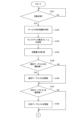
- FIG. 7 is a flowchart that defines an operation procedure when the vehicle service management device according to the embodiment of the present disclosure performs the evacuation determination process.
- FIG. 8 is a flowchart that defines an operation procedure when the vehicle service management device according to the embodiment of the present disclosure performs the evacuation determination process.
- FIG. 9 is a diagram illustrating an example of a processing sequence of the vehicle service management device and the in-vehicle device in the in-vehicle system according to the embodiment of the present disclosure.
- FIG. 10 is a diagram illustrating an example of a configuration of an in-vehicle system according to a first modification of the embodiment of the present disclosure.
- FIG. 10 is a diagram illustrating an example of a configuration of an in-vehicle system according to a first modification of the embodiment of the present disclosure.
- FIG. 11 is a diagram illustrating an example of a configuration of a vehicle service management device according to a first modification of the embodiment of the present disclosure.
- FIG. 12 is a diagram illustrating an example of a correspondence table after being updated by a vehicle service management device according to the first modification of the embodiment of the present disclosure.
- FIG. 13 is a diagram illustrating an example of a statistical table after updating by the vehicle service management device according to the first modification of the embodiment of the present disclosure.
- FIG. 14 is a diagram illustrating another example of the statistical table after updating by the vehicle service management device according to the first modification of the embodiment of the present disclosure.
- FIG. 15 is a diagram illustrating an example of a correspondence table stored by a vehicle service management device according to the second modification of the embodiment of the present disclosure.
- a service being executed while a vehicle is stopped or parked can be evacuated at an appropriate time.
- the judgment unit may make a positive judgment regarding the evacuation when the battery capacity monitored by the monitoring unit is equal to or less than a value obtained by adding a predetermined margin value to the evacuation capacity acquired by the evacuation capacity acquisition unit in the evacuation judgment process.
- the vehicle may be equipped with a plurality of on-board devices, and the vehicle service management device may further include an identification unit that, when the determination unit makes a positive determination regarding the evacuation in the evacuation determination process, identifies, among the plurality of on-board devices, a service-compatible device that is the on-board device that corresponds to the target service being executed, and a stop processing unit that performs a stop process to stop the operation of the service-compatible device identified by the identification unit.
- This configuration makes it possible to stop the operation of the in-vehicle device corresponding to the service to be evacuated, so that the evacuation of the service can be performed more reliably.
- the stop processing unit may further acquire sequence information indicating a correspondence relationship between the target service and an order in which the operation of the multiple service-enabled devices is stopped, and the stop processing unit may perform the stop processing according to the corresponding sequence, which is the sequence corresponding to the target service that is being executed, based on the acquired sequence information.
- the order information can be used to easily determine the order in which to stop the operation of the multiple service-enabled devices.
- the vehicle service management device may further include a power measurement unit that measures the power consumption of each of the service-enabled devices, a stop time measurement unit that measures the stop time required for each of the service-enabled devices to stop operating, and a sequence information update unit that updates the response sequence in the sequence information based on the power consumption measured by the power measurement unit and the stop time measured by the stop time measurement unit.
- the operation of the multiple service-enabled devices can be stopped in an appropriate order according to the actual measured power consumption and shutdown time of each service-enabled device.
- the evacuation capacity acquisition unit may further acquire capacity information indicating a correspondence between the target service and the evacuation capacity, and the evacuation capacity acquisition unit may acquire the evacuation capacity corresponding to the running target service based on the acquired capacity information.
- the capacity information can be used to easily obtain the evacuation capacity to be used in the evacuation determination process.
- the vehicle service management device may further include a capacity information update unit that updates, based on the battery capacity monitored by the monitoring unit, the saved capacity in the capacity information that corresponds to the target service that was being executed when the monitoring unit monitored the battery capacity.
- the battery capacity required to evacuate the target service may change due to factors such as battery deterioration.
- the evacuation decision process can be performed using an appropriate evacuation capacity according to the battery state, allowing for more accurate decisions regarding the evacuation of the target service.
- a vehicle service management method is a vehicle service management method in a vehicle service management device mounted on a vehicle, and includes the steps of monitoring a battery capacity, which is the capacity of a battery provided in the vehicle, when the vehicle is in a target state in which the vehicle is stopped or parked, acquiring a storage capacity, which is the capacity of the battery required for storage of a service executed in the vehicle, the storage capacity required for storage of a target service, which is the service executed in the target state, and performing an evacuation determination process to determine the evacuation of the target service being executed based on the monitored battery capacity and the acquired evacuation capacity.
- a vehicle service management program is a vehicle service management program used in a vehicle service management device mounted on a vehicle, and causes a computer to function as a monitoring unit that monitors a battery capacity, which is the capacity of a battery provided in the vehicle, when the vehicle is in a target state in which the vehicle is stopped or parked; a storage capacity acquisition unit that acquires a storage capacity, which is the capacity of the battery required for the storage of a service executed in the vehicle, the storage capacity required for the storage of a target service, which is the service executed in the target state; and a judgment unit that performs an evacuation judgment process that judges the evacuation of the target service being executed based on the battery capacity monitored by the monitoring unit and the evacuation capacity acquired by the evacuation capacity acquisition unit.
- Fig. 1 is a diagram showing an example of a configuration of an in-vehicle system according to an embodiment of the present disclosure.
- the in-vehicle system 301 includes a vehicle service management device 101, one or more in-vehicle devices 202, a power supply unit 51, and a relay 71.
- Fig. 1 shows, as an example, a case in which the in-vehicle system 301 includes a plurality of in-vehicle devices 202.
- the in-vehicle system 301 is mounted on a vehicle 1.
- the in-vehicle device 202 is, for example, an in-vehicle ECU (Electronic Control Unit). Specifically, the in-vehicle device 202 is a TCU (Telematics Communication Unit), an engine ECU, a body control ECU, an autonomous driving ECU, an ECU for face recognition, an ECU for door locks, etc. Note that the in-vehicle device 202 is not limited to an in-vehicle ECU, and may be an OTA (Over The Air) master, a sensor, a navigation device, a human-machine interface, a camera, etc.
- OTA Over The Air
- the vehicle service management device 101 and each in-vehicle device 202 communicate with each other to provide various services, i.e., applications, in the vehicle 1.
- Vehicle 1 executes a lighting control service that controls the timing of lighting the headlights of vehicle 1, a perimeter monitoring service that monitors the perimeter of vehicle 1, and a software update service that updates various software used in in-vehicle network 401 via OTA (Over the Air).
- the lighting control service is executed, for example, when vehicle 1 is traveling.
- the perimeter monitoring service and software update service are executed, for example, when vehicle 1 is in a target state where vehicle 1 is parked.
- the in-vehicle device 202 transitions from a wake-up mode to a sleep mode and from a sleep mode to a wake-up mode.
- the wake-up mode the in-vehicle device 202 communicates with other devices in the in-vehicle system 301, and in the sleep mode, the in-vehicle device 202 stops communication with other devices in the in-vehicle system 301.
- the sleep mode is a state in which power consumption is smaller than that in the wake-up mode due to the suspension of some functions of the in-vehicle device 202 or a decrease in the clock frequency of the in-vehicle device 202.
- the in-vehicle device 202 is in the sleep mode, it is possible for the in-vehicle device 202 to receive a CAN frame.
- sleep conditions which are conditions for transitioning the in-vehicle device 202 to a sleep mode
- wake-up conditions which are conditions for transitioning the in-vehicle device 202 to a wake-up mode
- the sleep conditions are when vehicle 1 is parked, when vehicle 1 is stopped, when vehicle 1 has its ignition turned off, etc.
- the wake-up conditions are when vehicle 1 starts to move, when vehicle 1 has its ignition turned on, etc.
- the in-vehicle device 202 transmits a CAN frame (hereinafter also referred to as an "NM frame") that stores an NM (Network Management) message conforming to the AUTOSAR (AUTOmotive Open System Architecture) (registered trademark) to each device in the in-vehicle system 301.
- NM frame a CAN frame
- AUTOSAR AUTOmotive Open System Architecture
- each in-vehicle device 202 broadcasts an NM frame to each device for alive monitoring, for example.
- the in-vehicle device 202 when the in-vehicle device 202's own operation mode transitions from wake-up mode to sleep mode, it stops transmitting NM frames.
- the power supply unit 51 supplies power in the vehicle 1.
- the power supply unit 51 is connected to the vehicle service management device 101 via a power line 4.
- the power supply unit 51 supplies power to the vehicle service management device 101 via the power line 4.
- the power supply unit 51 is connected to each in-vehicle device 202 via the power line 5.
- the power supply unit 51 supplies power to each in-vehicle device 202 via the power line 5.
- the power supply unit 51 is connected to each in-vehicle device 202 connected to the CAN bus 2A via, for example, the power supply line 5A, which is the power supply line 5.
- Each in-vehicle device 202 connected to the CAN bus 2A operates using the power supplied by the power supply unit 51.
- the power supply unit 51 is also connected to each of the in-vehicle devices 202 connected to the CAN bus 2B, for example, via the power supply line 5B, which is the power supply line 5.
- Each of the in-vehicle devices 202 connected to the CAN bus 2B operates using the power supplied by the power supply unit 51.
- the power supply unit 51 includes, for example, a main battery 61 and a sub-battery 62.
- the power supply source for each device is switched between the main battery 61 and the sub-battery 62 depending on the state of the vehicle 1, etc.
- the main battery 61 supplies power to each device in the in-vehicle system 301 while the vehicle 1 is traveling. Also, for example, when the capacity of the sub-battery 62 (hereinafter also referred to as "sub-battery capacity") is less than a predetermined threshold Th1 while the vehicle 1 is parked, the main battery 61 supplies power to each device. When the sub-battery capacity is equal to or greater than the threshold Th1 while the vehicle 1 is parked, the sub-battery 62 supplies power to each device.
- sub-battery capacity hereinafter also referred to as "sub-battery capacity”
- relay 71 is a device for switching the power supply source for each device in in-vehicle system 301 between main battery 61 and sub-battery 62.
- In-vehicle system 301 includes, for example, relays 71A and 71B.
- Relay 71A is connected between the main battery 61 and each in-vehicle device 202.
- Relay 71B is connected between the sub-battery 62 and each in-vehicle device 202.
- Relays 71A and 71B switch between the on and off states according to the control of a relay control device (not shown) in the in-vehicle system 301.
- relay 71A when the ignition power supply of vehicle 1 is turned on, relay 71A is in the on state and relay 71B is in the off state. Also, for example, when the ignition power supply is turned off and the sub-battery capacity is less than threshold value Th1, relay 71A is in the on state and relay 71B is in the off state. Also, for example, when the ignition power supply is turned off and the sub-battery capacity is greater than threshold value Th1, relay 71A is in the off state and relay 71B is in the on state.
- the in-vehicle system 301 is not limited to a configuration in which two CAN buses 2 are provided, and may be a configuration in which one or three or more CAN buses 2 are provided.
- vehicle service management device 101 and the in-vehicle device 202 may be configured to communicate in accordance with a communication protocol such as CAN FD (CAN with Flexible Data Rate), Ethernet (registered trademark), FlexRay (registered trademark), MOST (Media Oriented System Transport) (registered trademark), LIN (Local Interconnect Network), and CXPI (Clock Extension Peripheral Interface) (registered trademark), instead of or in addition to communication in accordance with the CAN standard.
- CAN FD CAN with Flexible Data Rate
- Ethernet registered trademark
- FlexRay registered trademark
- MOST Media Oriented System Transport
- LIN Local Interconnect Network
- CXPI Chip Extension Peripheral Interface
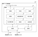
- FIG. 2 is a diagram showing an example of the configuration of a vehicle service device according to an embodiment of the present disclosure.
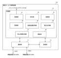
- the vehicle service management device 101 includes a communication unit 11, a processing unit 12, and a storage unit 13.
- the processing unit 12 includes a management unit 21, a specification unit 22, a control unit 23, a monitoring unit 24, a storage capacity acquisition unit 25, a power measurement unit 26, a stop time measurement unit 27, and an update unit 28.
- One or both of the communication unit 11 and the processing unit 12 are realized, for example, by a processing circuit (Circuitry) including one or more processors.
- the storage unit 13 is, for example, a non-volatile memory included in the processing circuit.
- the management unit 21 is an example of a determination unit.
- the control unit 23 is an example of a stop processing unit.
- the management unit 21 performs a state determination process to determine whether or not the vehicle 1 is in a target state. More specifically, for example, the management unit 21 monitors the output voltage of an ignition power supply of the vehicle 1 in the state determination process.
- the management unit 21 measures the output voltage of the ignition power supply of the vehicle 1, and if the measured voltage value is less than a predetermined threshold value Th2, it determines that the vehicle 1 is parked, i.e., in the target state. In this case, each in-vehicle device 202 transitions to the sleep mode because the sleep condition is satisfied.
- the management unit 21 determines that the vehicle 1 is not in the target state.
- the storage unit 13 stores type information indicating the type of service (hereinafter also referred to as the "target service") to be executed in the target state.
- the type information indicates, for example, a perimeter monitoring service and a software update service as the types of the target service.
- the management unit 21 determines that the vehicle 1 is in a target state, it acquires type information from the storage unit 13. Then, the management unit 21 outputs the acquired type information to the identification unit 22 and the storage capacity acquisition unit 25.
- the identification unit 22 When the identification unit 22 receives type information from the management unit 21, it identifies the in-vehicle device 202 (hereinafter also referred to as the "service-compatible device") that corresponds to the target service indicated by the type information.
- the in-vehicle device 202 hereinafter also referred to as the "service-compatible device”
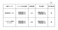
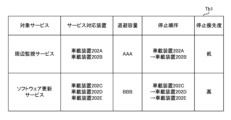
- the storage unit 13 stores a correspondence table Tb1 that indicates a correspondence relationship E1 between a target service and a service-compatible device.
- the correspondence table Tb1 is registered in the storage unit 13 by the manufacturer of the vehicle 1, for example, when the vehicle 1 is shipped.
- the correspondence table Tb1 is an example of sequence information and an example of capacity information.
- FIG. 3 is a diagram showing an example of a correspondence table stored by a vehicle service management device according to an embodiment of the present disclosure.
- the service-compatible device (hereinafter also referred to as “service-compatible device S1") that corresponds to the perimeter monitoring service is the vehicle-mounted devices 202A and 202B.
- the service-compatible device (hereinafter also referred to as “service-compatible device S2”) that corresponds to the software update service is the vehicle-mounted devices 202C and 202D.
- the "Saving capacity”, “Stop order”, and “Stop priority” shown in FIG. 3 will be described later.
- the identification unit 22 When the identification unit 22 receives type information from the management unit 21, it identifies the service-compatible devices S1 and S2 by referring to the correspondence table Tb1 in the storage unit 13. Then, the identification unit 22 outputs device information D1 indicating the identified service-compatible devices S1 and S2 to the control unit 23.
- the storage unit 13 further stores a CAN table indicating the correspondence between the in-vehicle device 202 and the CAN-ID.
- control unit 23 When the control unit 23 receives the device information D1 from the identification unit 22, it identifies the CAN-ID corresponding to the service-compatible device S1 indicated by the device information D1 by referring to the CAN table in the storage unit 13. Specifically, the control unit 23 identifies the CAN-ID corresponding to the in-vehicle device 202A and the CAN-ID corresponding to the in-vehicle device 202B.
- the control unit 23 also identifies the CAN-ID corresponding to the service-compatible device S2 indicated by the device information D1. Specifically, the control unit 23 identifies the CAN-ID corresponding to the in-vehicle device 202C and the CAN-ID corresponding to the in-vehicle device 202D.
- control unit 23 When the control unit 23 identifies the CAN-ID corresponding to each service-enabled device, it creates a CAN frame (hereinafter also referred to as a "wake-up request frame") that includes the identified CAN-ID and a wake-up request, and outputs it to the communication unit 11.
- a CAN frame hereinafter also referred to as a "wake-up request frame”
- the memory unit 13 further stores a routing table that indicates the correspondence between the CAN-ID and the CAN bus to which the destination of the CAN frame is connected (hereinafter also referred to as the "destination bus").
- the communication unit 11 When the communication unit 11 receives a wake-up request frame from the control unit 23, it refers to the routing table in the memory unit 13 to identify the destination bus that corresponds to the CAN-ID included in the wake-up request frame, and outputs the wake-up request frame to the identified destination bus.
- each service-compatible device When each service-compatible device receives a wake-up request frame from the vehicle service management device 101, it transitions to wake-up mode.
- each service-compatible device when each service-compatible device receives a wake-up request frame from the vehicle service management device 101, it checks whether its own CAN-ID is included in the wake-up request frame.
- a service-enabled device operating in sleep mode discards CAN frames that do not include its own CAN-ID.
- a service-enabled device operating in sleep mode receives a wake-up request frame that includes its own CAN-ID, it starts up a power supply IC (Integrated Circuitry) (not shown) provided in the service-enabled device and transitions to wake-up mode.
- the service-enabled device communicates with other devices in the in-vehicle system 301 using the output voltage of the power supply IC.
- the inventors of the present application have discovered that while the vehicle 1 is stopped or parked, the main battery 61 and the sub-battery 62 are not charged or are charged insufficiently, and therefore it is likely to become difficult to maintain the target service due to a decrease in the capacity of at least one of the main battery 61 and the sub-battery 62. For example, if the power supply to the in-vehicle device 202 corresponding to the target service is stopped at an unintended timing, a malfunction such as a hang-up or failure occurs in the in-vehicle device 202, which may adversely affect the provision of the service thereafter.
- the in-vehicle system 301 solves the above problem by adopting the following configuration and operation.
- the monitoring unit 24 in the vehicle service management device 101 monitors the capacity of the main battery 61 (hereinafter also referred to as the "main battery capacity") and the capacity of the sub-battery in the target state.
- the main battery capacity and the sub-battery capacity refer to the remaining capacity of the battery.
- the monitoring unit 24 measures the output current of the main battery 61 at every predetermined time Ta.
- the monitoring unit 24 also measures the elapsed time T2 from when the main battery 61 is fully charged.
- the monitoring unit 24 then multiplies the measured current value of the main battery 61 by the elapsed time T2 to calculate the used capacity of the main battery 61.
- the monitoring unit 24 also measures the output current of the sub-battery 62 at each time Ta.
- the monitoring unit 24 also measures the elapsed time T3 from when the sub-battery 62 is fully charged.
- the monitoring unit 24 then multiplies the measured current value of the sub-battery 62 by the elapsed time T3 to calculate the usage capacity of the sub-battery 62.
- the memory unit 13 stores, for example, the capacity of the main battery 61 when fully charged and the capacity of the sub-battery 62 when fully charged.
- the monitoring unit 24 calculates the usage capacity of the main battery 61, it subtracts the usage capacity from the capacity of the main battery 61 when fully charged, which is stored in the memory unit 13, to calculate the main battery capacity.
- the monitoring unit 24 calculates the usage capacity of the sub-battery 62, it subtracts the usage capacity from the capacity of the sub-battery 62 when fully charged, which is stored in the memory unit 13, to calculate the sub-battery capacity.
- the monitoring unit 24 outputs calculation result information indicating the calculated main battery capacity and sub-battery capacity to the management unit 21.
- the save capacity acquisition unit 25 acquires the capacity of the main battery 61 and the sub-battery 62 required for saving the target service (hereinafter also referred to as "save capacity").
- the correspondence table Tb1 in the storage unit 13 indicates, in addition to the correspondence relationship E1, a correspondence relationship E2 between the target service and the backup capacity.
- the save capacity C1 corresponding to the perimeter monitoring service is "AAA” milliampere-hours.
- the save capacity C2 corresponding to the software update service is "BBB” milliampere-hours.
- the save capacity acquisition unit 25 When the save capacity acquisition unit 25 receives information from the type information from the management unit 21, it acquires the correspondence table Tb1 from the storage unit 13. Then, the save capacity acquisition unit 25 acquires the save capacity corresponding to the target service being executed based on the acquired correspondence table Tb1.
- the save capacity acquisition unit 25 when the save capacity acquisition unit 25 receives information from the type information from the management unit 21, it reads the correspondence table Tb1 in the storage unit 13. Then, by referring to the correspondence table Tb1, the save capacity acquisition unit 25 identifies the save capacity C1 corresponding to the peripheral monitoring service indicated by the type information, and the save capacity C2 corresponding to the software update service. Then, the save capacity acquisition unit 25 outputs save capacity information indicating the identified save capacities C1 and C2 to the management unit 21.
- the management unit 21 performs a save determination process to determine whether to save a target service that is being executed, based on the main battery capacity and the sub-battery capacity monitored by the monitoring unit 24 and the save capacity acquired by the save capacity acquisition unit 25.
- the management unit 21 when the management unit 21 receives the storage capacity information from the storage capacity acquisition unit 25, it calculates a value (hereinafter referred to as "reference value A") obtained by adding a predetermined margin value M to the total value of the storage capacity C1 and the storage capacity C2 indicated by the storage capacity information.
- reference value A a value obtained by adding a predetermined margin value M to the total value of the storage capacity C1 and the storage capacity C2 indicated by the storage capacity information.
- the management unit 21 makes a positive determination regarding the evacuation of the target service being executed.
- the management unit 21 determines to evacuate the peripheral monitoring service and software update service that are currently being executed.
- the management unit 21 When the management unit 21 completes the evacuation determination process, it outputs evacuation determination information indicating the types of target services that have been determined to be evacuated, i.e., the peripheral monitoring service and the software update service, to the identification unit 22.
- the management unit 21 decides not to evacuate the target service that is being executed.
- the identification unit 22 identifies a service supporting device.
- the identification unit 22 when the identification unit 22 receives evacuation judgment information from the management unit 21, the identification unit 22 refers to the correspondence table Tb1 in the storage unit 13 to identify multiple service-compatible devices S1 that correspond to the surrounding monitoring service indicated by the evacuation judgment information. The identification unit 22 also identifies multiple service-compatible devices S2 that correspond to the software update service indicated by the evacuation judgment information.
- the identification unit 22 outputs to the control unit 23 device information D2 indicating the type of target service indicated by the evacuation judgment information received from the management unit 21 and multiple service-compatible devices corresponding to the target service.
- control unit 23 performs a stop process to stop the operation of the multiple service supporting devices identified by the identification unit 22 .
- the correspondence table Tb1 in the storage unit 13 indicates, in addition to the correspondence relationships E1 and E2, a correspondence relationship E3 between a target service and an order in which the operations of a plurality of service supporting devices are stopped.
- the stop order corresponding to the perimeter monitoring service is first for in-vehicle device 202A, and second for in-vehicle device 202B.
- the stop order corresponding to the software update service is first for in-vehicle device 202C, and second for in-vehicle device 202D.
- the control unit 23 identifies the order in which the devices correspond to the target service being executed (hereinafter also referred to as the "corresponding order") based on the correspondence table Tb1 obtained from the memory unit 13.
- control unit 23 When the control unit 23 receives the device information D2 from the identification unit 22, it reads out the correspondence table Tb1 from the storage unit 13. Then, the control unit 23 refers to the correspondence table Tb1 to identify the response order corresponding to the perimeter monitoring service indicated by the device information D2 and the response order corresponding to the software update service.
- ⁇ Stop processing priority> When the device information D2 received from the identification unit 22 indicates a plurality of target services, the control unit 23 performs the stop process on the target services in descending order of priority.
- the correspondence table Tb1 in the memory unit 13 indicates, in addition to the correspondence relationships E1 to E3, a correspondence relationship E4 between the target service and the priority of the stop process (hereinafter also referred to as the "stop priority").
- the stop priority of the perimeter monitoring service is low, and the stop priority of the software update service is high.
- control unit 23 When the control unit 23 identifies the response order of each target service indicated by the device information D2 received from the identification unit 22, it checks the stop priority of each target service by referring to the response table Tb1 in the storage unit 13.
- control unit 23 checks the stop priority of each target service, it performs the stop process according to the checked stop priority.
- control unit 23 when the control unit 23 checks the stop priority corresponding to each target service, it performs a stop process on the multiple service-compatible devices corresponding to the target service with the highest stop priority according to the identified response order.
- control unit 23 sends a sleep request frame via the communication unit 11 and the destination bus to each service-compatible device corresponding to the target service with the highest stop priority, according to the identified response order.
- the control unit 23 since the software update service is the target service with the highest stop priority, the control unit 23 transmits a sleep request frame to the in-vehicle devices 202C and 202D that correspond to the software update service.
- control unit 23 When the control unit 23 transmits a sleep request frame to the in-vehicle devices 202C and 202D, it performs a stop process for the multiple service-compatible devices corresponding to the target service with the second highest stop priority according to the identified response order.
- the control unit 23 transmits a sleep request frame to the in-vehicle devices 202A and 202B corresponding to the perimeter monitoring service via the communication unit 11 and the destination bus, in the same manner as the stop process for the in-vehicle devices 202C and 202D.
- control unit 23 When the control unit 23 transmits a sleep request frame to each service-compatible device, it outputs a transmission notification N1 indicating that the sleep request frame has been transmitted to the monitoring unit 24 and the stop time measurement unit 27.
- each service-compatible device When each service-compatible device receives a sleep request frame from the vehicle service management device 101, it transitions to sleep mode. Also, when each service-compatible device receives a sleep request frame from the vehicle service management device 101, it saves various information while the target service is being executed in a storage unit (not shown). Specifically, for example, when a camera, which is an example of a service-compatible device that executes a perimeter monitoring service, receives a sleep request frame from the vehicle service management device 101, it saves information indicating its own startup time while the perimeter monitoring service is being executed, as well as captured images, etc., in the storage unit of the camera.
- Power measurement section 1 and 2 again, for example, power measurement unit 26 measures the power consumption of each service supporting device.
- the power measurement unit 26 measures, for example periodically, the current flowing through the power line 5 connected to each service-enabled device.
- the power measurement unit 26 measures the voltage of the power line 5 connected to each service-compatible device, for example, periodically. For example, the power measurement unit 26 measures the voltage at the same timing as the measurement of the current flowing through the power line 5.
- the power measurement unit 26 uses the measured current and voltage values to calculate the power consumption of each service-enabled device at the measurement time, and stores power calculation information G11 indicating the calculation results in the memory unit 13.
- the power measurement unit 26 calculates the statistical value of the power consumption of each service-compatible device every time a predetermined time T11 has elapsed since the target state was entered.
- the power measurement unit 26 calculates the average power consumption for each service-enabled device using the power calculation information G11 stored in the memory unit 13 during a predetermined time T11. The power measurement unit 26 then outputs the calculation result, i.e., power statistical information G21 indicating the average power consumption of each service-enabled device, to the update unit 28.
- the downtime measurement unit 27 measures the downtime required for each service supporting device to stop operating.
- stop time measurement unit 27 when the stop time measurement unit 27 receives a transmission notification N1 from the control unit 23, it starts a timer (not shown).
- the control unit 23 If a new NM frame does not arrive from a service-enabled device even after a certain time has elapsed since the control unit 23 sent a sleep request frame to the multiple service-enabled devices via the communication unit 11, the control unit 23 outputs a stop notification N2 indicating that the service-enabled device has stopped operating to the stop time measurement unit 27.
- the control unit 23 confirms that a new NM frame has not arrived for the multiple service-enabled devices, and outputs a stop notification N2 for each service-enabled device to the stop time measurement unit 27.
- control unit 23 when new NM frames stop arriving from all service-compatible devices for a certain target service, the control unit 23 outputs a termination notification N3 to the monitoring unit 24, indicating that all service-compatible devices have stopped operating.
- the stop time measurement unit 27 When the stop time measurement unit 27 receives a stop notification N2 from the control unit 23, it measures the time from when the timer is started until the stop notification N2 is received as the stop time of the service-compatible device indicated by the stop notification N2. Then, the stop time measurement unit 27 outputs stop time information K11 indicating the stop time for each service-compatible device to the update unit 28.
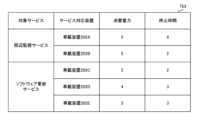
- FIG. 4 is a diagram illustrating an example of a statistical table stored by the vehicle service management device according to the embodiment of the present disclosure.
- the storage unit 13 further stores a statistical table Tb2 indicating the correspondence between the type of target service, the service-compatible device, the relative value R1 of power consumption, and the relative value R2 of downtime.
- the statistical table Tb2 is registered in the storage unit 13 by the manufacturer of the vehicle 1, for example, when the vehicle 1 is shipped.
- FIG. 4 shows the statistical table Tb2 registered in the memory unit 13 at the time of shipment of the vehicle 1. Therefore, in the statistical table Tb2 shown in FIG. 4, the relative value R1 of power consumption and the relative value R2 of downtime of each service-compatible device that executes the perimeter monitoring service are "not applicable.” Also, the relative value R1 of power consumption and the relative value R2 of downtime of each service-compatible device that executes the software update service are "not applicable.”
- Update statistics table When the update unit 28 receives the power statistical information G21 from the power measurement unit 26, it determines whether or not to update the statistical table Tb2 in the storage unit 13.
- the storage unit 13 stores a predicted value of power consumption in a target state for each service-compatible device.
- the update unit 28 When the update unit 28 receives the power statistical information G21 from the power measurement unit 26, it stores the power statistical information G21 in the storage unit 13. In addition, the update unit 28 calculates, for each service-compatible device, a relative power consumption value R1 by dividing the average power consumption indicated by the power statistical information G21 by the predicted power consumption value stored in the storage unit 13.
- the update unit 28 receives the first power statistical information G21 from the power measurement unit 26, it determines to update the statistical table Tb2. Then, the update unit 28 performs an update process L1 in which the calculated relative value R1 is associated with the service compatible device and registered in the statistical table Tb2.
- the update unit 28 receives the second or subsequent power statistical information G21 from the power measurement unit 26, it checks whether the currently calculated relative value R1 is the same as the relative value R1 of the power consumption of the corresponding service corresponding device in the statistical table Tb2 stored in the memory unit 13. If the currently calculated relative value R1 is the same as the relative value R1 of the power consumption of the corresponding service corresponding device in the statistical table Tb2, the update unit 28 determines not to update the statistical table Tb2.
- the update unit 28 determines to update the statistics table Tb2. Then, the update unit 28 performs update processing L1 on the statistics table Tb2.
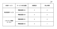
- FIG. 5 is a diagram showing an example of a statistical table after updating by a vehicle service management device according to an embodiment of the present disclosure.
- the relative value R1 of the power consumption of the in-vehicle device 202A is "2".
- the relative value R1 of the power consumption of the in-vehicle device 202B is "5".
- the relative value R1 of the power consumption of the in-vehicle device 202C is "4".
- the relative value R1 of the power consumption of the in-vehicle device 202D is "3".
- the update unit 28 receives the stop time information K11 from the stop time measurement unit 27, it determines whether or not to update the statistical table Tb2.
- the storage unit 13 stores a predicted value of downtime for each service-enabled device.
- the update unit 28 When the update unit 28 receives the downtime information K11 from the power measurement unit 26, it stores the downtime information K11 in the storage unit 13. In addition, the update unit 28 calculates, for each service-compatible device, a value obtained by dividing the downtime indicated by the downtime information K11 by the predicted value of the downtime stored in the storage unit 13 as a relative value R2 of the downtime.
- the update unit 28 receives the second or subsequent stop time information K11 from the stop time measurement unit 27, it checks whether the currently calculated relative value R2 is the same as the relative value R2 of the stop time of the corresponding service corresponding device in the statistics table Tb2 stored in the memory unit 13. If the currently calculated relative value R2 is the same as the relative value R2 of the stop time of the corresponding service corresponding device in the statistics table Tb2, the update unit 28 determines not to update the statistics table Tb2.
- the update unit 28 determines to update the statistics table Tb2. Then, the update unit 28 performs update processing L2 on the statistics table Tb2.
- the relative value R2 of the stopped time of the in-vehicle device 202A is "4".
- the relative value R2 of the stopped time of the in-vehicle device 202B is “2”.
- the relative value R2 of the stopped time of the in-vehicle device 202C is "3”.
- the relative value R2 of the stopped time of the in-vehicle device 202D is "1".
- the update unit 28 updates the correspondence order in the correspondence table Tb1 based on the power consumption measured by the power measurement unit 26 and the downtime measured by the downtime measurement unit 27 .
- the update unit 28 when the update unit 28 newly registers a power consumption relative value R1 and a stop time relative value R2 in the statistical table Tb2, it calculates a value (hereinafter also referred to as "multiplication value B") obtained by multiplying the corresponding relative values R1 and R2 for each service-compatible device.
- multiplication value B a value obtained by multiplying the corresponding relative values R1 and R2 for each service-compatible device.
- the update unit 28 calculates the multiplication value B for each service-compatible device, and then determines the correspondence order based on the calculated multiple multiplication values B.
- the update unit 28 determines to stop the service-enabled devices in order starting from the service-enabled devices corresponding to the multiplication value B with the smallest value.
- the update unit 28 After determining the correspondence order for each target service, the update unit 28 reads the correspondence table Tb1 in the storage unit 13. The update unit 28 then refers to the correspondence table Tb1 to check whether the determined correspondence order for each target service is the same as the correspondence order indicated in the correspondence table Tb1.
- the update unit 28 decides not to update the correspondence relationship E3 in the correspondence table Tb1. On the other hand, if the determined correspondence order is different from the correspondence order shown in the correspondence table Tb1, the update unit 28 updates the correspondence relationship E3 in the correspondence table Tb1.
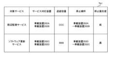
- FIG. 6 shows an example of a correspondence table after updating by a vehicle service management device according to an embodiment of the present disclosure.
- the correspondence order of the software update services has been changed so that the first correspondence is in-vehicle device 202D and the second correspondence is in-vehicle device 202C, compared to the correspondence table Tb1 shown in FIG. 3.
- the update unit 28 updates the evacuation capacity in the correspondence table Tb1 corresponding to the target service that was being executed when the monitoring unit 24 monitored the main battery capacity and the sub-battery capacity based on the main battery capacity and the sub-battery capacity monitored by the monitoring unit 24.
- the monitoring unit 24 when the monitoring unit 24 receives a transmission notification N1 from the control unit 23, it outputs calculation result information P1 indicating the most recent main battery capacity and sub-battery capacity to the update unit 28.
- the monitoring unit 24 when the monitoring unit 24 receives a termination notification N3 from the control unit 23, it outputs calculation result information P2 indicating the most recent main battery capacity and sub-battery capacity to the update unit 28.
- the update unit 28 When the update unit 28 receives the calculation result information P1 and P2, it calculates the saved capacity by subtracting the total value of the main battery capacity and the sub-battery capacity indicated by the calculation result information P2 from the total value of the main battery capacity and the sub-battery capacity indicated by the calculation result information P1.
- the update unit 28 After calculating the evacuation capacity for each target service, the update unit 28 reads the correspondence table Tb1 in the storage unit 13. The update unit 28 then refers to the correspondence table Tb1 to check whether the calculated evacuation capacity for each target service is the same as the evacuation capacity indicated in the correspondence table Tb1.
- FIGS. 7 and 8 are flowcharts that define an operation procedure when the vehicle service management device according to the embodiment of the present disclosure performs the evacuation determination process.
- the vehicle service management device 101 determines whether the vehicle 1 is in a target state (step S101), and if it is determined that the vehicle 1 is in a target state (YES in step S101), it identifies a service-compatible device that corresponds to the target service.
- the vehicle service management device 101 identifies multiple service-compatible devices (step S102).
- the vehicle service management device 101 transmits a wake-up request frame to each of the identified service-enabled devices to transition the devices to the wake-up mode (step S103).
- the vehicle service management device 101 measures the power consumption of each service-compatible device. For example, as described above, the vehicle service management device 101 periodically measures the power consumption of each service-compatible device and stores power calculation information G11 indicating the measurement results in the memory unit 13 (step S104).
- the vehicle service management device 101 determines whether or not to update the relative value R1 of power consumption indicated in the statistical table Tb2 in the memory unit 13. For example, as described above, the vehicle service management device 101 calculates the relative value R1 of power consumption for each service corresponding device. Then, the vehicle service management device 101 checks whether the calculated relative value R1 is the same as the relative value R1 of the corresponding service corresponding device in the statistical table Tb2 (step S105).
- step S105 when the vehicle service management device 101 determines that the statistical table Tb2 should be updated (YES in step S105), it performs an update process L1 in which the currently calculated relative value R1 is registered in the statistical table Tb2 in association with the service-compatible device (step S106).
- the vehicle service management device 101 determines whether to update the correspondence relationship E3 between the type of target service and the stop order indicated in the correspondence table Tb1 in the memory unit 13. For example, as described above, the vehicle service management device 101 calculates a multiplication value B by multiplying the corresponding power consumption relative value R1 and the stop time relative value R2 for each service-compatible device, and determines the stop order based on the calculated multiple multiplication values B. The vehicle service management device 101 then checks whether the determined stop order is the same as the stop order indicated in the correspondence table Tb1 (step S107).
- step S107 when the vehicle service management device 101 determines that the correspondence table Tb1 should be updated (YES in step S107), it updates the correspondence relationship E3 in the correspondence table Tb1 (step S108).
- the vehicle service management device 101 checks whether both the main battery capacity and the sub-battery capacity are below the reference value A (step S109).
- step S109 if both the main battery capacity and the sub-battery capacity are equal to or less than the reference value A (YES in step S109), the vehicle service management device 101 determines to evacuate the target service being executed (step S110).
- the vehicle service management device 101 identifies a service-compatible device that corresponds to the target service being executed.
- the vehicle service management device 101 identifies multiple service-compatible devices (step S111).
- the vehicle service management device 101 performs a stop process to stop the operation of the identified service-enabled devices. For example, as described above, the vehicle service management device 101 transmits a sleep request frame to each identified service-enabled device (step S112).
- the vehicle service management device 101 determines that the relative value R2 of the stop time indicated in the statistical table Tb2 should be updated (YES in step S114), it performs an update process L2 in which the relative value R2 calculated this time is registered in the statistical table Tb2 in association with the service corresponding device (step S115).
- the vehicle service management device 101 calculates the amount of storage space required to evacuate the target service that was being executed (step S116).
- the vehicle service management device 101 determines to update the correspondence table Tb1 (YES in step S117), it updates at least one of the correspondence relationship E3 between the service-compatible devices and the stop order and the correspondence relationship E2 between the service-compatible devices and the backup capacity in the correspondence table Tb1 (step S118).
- FIG. 9 is a diagram showing an example of a processing sequence of a vehicle service management device and an in-vehicle device in an in-vehicle system according to an embodiment of the present disclosure.
- the vehicle service management device 101 determines that vehicle 1 is in a target state (step S201).
- the vehicle service management device 101 identifies a service-compatible device that corresponds to the target service to be executed in the target state, and transmits a wake-up request frame to the identified service-compatible device.
- the vehicle service management device 101 identifies the vehicle-mounted devices 202A and 202B as the service-compatible devices, and transmits a wake-up request frame to the vehicle-mounted devices 202A and 202B (steps S202 and S203).
- step S204 and S205 transition to the wake-up mode.
- the vehicle service management device 101 measures the power consumption of each of the in-vehicle devices 202A and 202B (step S206).
- the vehicle service management device 101 determines whether or not to update the relative value R1 of power consumption indicated in the statistical table Tb2. For example, as described above, the vehicle service management device 101 calculates the relative value R1 of power consumption for each service corresponding device. Then, the vehicle service management device 101 checks whether the calculated relative value R1 is the same as the relative value R1 of power consumption of the corresponding service corresponding device in the statistical table Tb2. Here, it is assumed that the vehicle service management device 101 has determined to update the relative value R1 indicated in the statistical table Tb2 (step S207).
- the vehicle service management device 101 determines whether or not to update the correspondence relationship E3 between the type of target service and the stop order in the correspondence table Tb1. Here, it is assumed that the vehicle service management device 101 has determined to update the correspondence relationship E3 (step S208).
- the vehicle service management device 101 checks whether or not both the main battery capacity and the sub-battery capacity are equal to or less than the reference value A.
- the vehicle service management device 101 checks whether both the main battery capacity and the sub-battery capacity are equal to or less than the reference value A (step S209).
- the vehicle service management device 101 identifies the in-vehicle devices 202A and 202B as service-compatible devices that correspond to the target service being executed, and transmits a sleep request frame to the in-vehicle devices 202A and 202B (steps S210 and S211).
- step S212 and S213 the in-vehicle devices 202A and 202B transition to sleep mode.
- the vehicle service management device 101 measures the stop time of each of the in-vehicle devices 202A and 202B (step S214).
- the vehicle service management device 101 determines whether or not to update the relative value R2 of the downtime indicated in the statistical table Tb2 in the memory unit 13. For example, as described above, the vehicle service management device 101 calculates the relative value R2 of the downtime for each service corresponding device. Then, the vehicle service management device 101 checks whether the calculated relative value R2 is the same as the relative value R2 of the downtime of the corresponding service corresponding device in the statistical table Tb2. Here, it is assumed that the vehicle service management device 101 has determined to update the relative value R2 indicated in the statistical table Tb2 (step S215).
- the vehicle service management device 101 calculates the evacuation capacity required to evacuate the target service that was being executed (step S216).
- the vehicle service management device 101 determines whether or not to update the correspondence table Tb1 in the storage unit 13. For example, as described above, the vehicle service management device 101 determines the stop order of multiple service compatible devices based on the multiplied value B of the power consumption relative value R1 and the stop time relative value R2 in the statistical table Tb2. The vehicle service management device 101 then checks whether the determined stop order is the same as the stop order indicated in the correspondence table Tb1. The vehicle service management device 101 also checks whether the calculated evacuation capacity is the same as the evacuation capacity indicated in the correspondence table Tb1. Here, it is assumed that the vehicle service management device 101 has determined to update the correspondence relationship E3 in the statistical table Tb2 (step S217).
- the vehicle service management device 101 is configured to determine whether or not the running target service needs to be evacuated in the evacuation determination process, but this is not limited to this.
- the vehicle service management device 101 may be configured to determine the probability that in the handling state, the total value of the main battery capacity and the sub-battery capacity will be equal to or less than the evacuation capacity of the running target service.
- the vehicle service management device 101 calculates, for each target service, a probability corresponding to the difference between the total value of the main battery capacity and the sub-battery capacity in the target state and the evacuation capacity indicated in the correspondence table Tb1, and performs a stop process if the calculated probability is equal to or greater than a predetermined threshold.
- the vehicle service management device 101 is configured to identify a service-compatible device and perform a stop process on the service-compatible device when a positive determination is made regarding the evacuation of the target service in the evacuation determination process, but this is not limited to this.
- the vehicle service management device 101 may be configured to notify the user of the vehicle 1 of the determination result, for example.
- the vehicle service management device 101 when performing stop processing on multiple service-compatible devices, is configured to identify a stop order corresponding to the target service being executed and perform the stop processing according to the identified stop order, but this is not limited to this.
- the vehicle service management device 101 may also be configured to simultaneously stop the operation of multiple service-compatible devices.
- the vehicle service management device 101 is configured to update the correspondence relationship E3 between the type of target service and the stop order in the correspondence table Tb1 based on the power consumption and stop time of the service-supporting device, but this is not limited to this.
- the vehicle service management device 101 may also be configured not to update the correspondence relationship E3 in the correspondence table Tb1.
- the vehicle service management device 101 is configured to calculate the relative value R1 of the power consumption and the relative value R2 of the downtime of each service-compatible device, but this is not limited to this.
- a device other than the vehicle service management device 101 for example a server outside the vehicle, may be configured to calculate the relative values R1 and R2.
- the vehicle service management device 101 is configured to acquire the evacuation capacity in the evacuation determination process using the correspondence table Tb1 indicating the correspondence relationship E2 between the type of target service and the evacuation capacity, but this is not limited to this.
- the vehicle service management device 101 may also be configured to calculate the evacuation capacity using, for example, a predetermined arithmetic formula in the evacuation determination process.
- the vehicle service management device 101 is configured to update the correspondence relationship E2 between the type of target service and the storage capacity in the correspondence table Tb1 based on the main battery capacity and the sub-battery capacity monitored while the target service is being executed, but this is not limited to this.
- the vehicle service management device 101 may also be configured not to update the correspondence relationship E2 in the correspondence table Tb1.
- the power supply unit 51 is configured to include two batteries, i.e., the main battery 61 and the sub-battery 62, but this is not limited to this.
- the power supply unit 51 may be configured to include one battery or three or more batteries.
- Fig. 10 is a diagram showing an example of the configuration of an in-vehicle system according to the first modification of the embodiment of the present disclosure.
- the in-vehicle system 302 compared to the in-vehicle system 301 shown in Fig. 1, the in-vehicle system 302 further includes an in-vehicle device 202E which is the in-vehicle device 202.
- the in-vehicle device 202E is connected to the vehicle service management device 101 via a CAN bus 2B.
- the in-vehicle device 202E is also connected to the power supply unit 51 via a power line 5B.
- the in-vehicle device 202 newly added to the in-vehicle network 401 will also be referred to as a "new device,” and the in-vehicle network 401 including the new device will also be referred to as a "new network.”
- FIG. 11 is a diagram showing an example of the configuration of a vehicle service management device according to Variation 1 of an embodiment of the present disclosure.
- the vehicle service management device 101A includes a communication unit 11, a processing unit 12A, and a storage unit 13.
- One or both of the communication unit 11 and the processing unit 12A are realized, for example, by a processing circuit including one or more processors.
- the storage unit 13 is, for example, a non-volatile memory included in the processing circuit.
- the processing unit 12A further includes an addition detection unit 29.
- the addition detection unit 29 detects the addition of the in-vehicle device 202 to the in-vehicle network 401.
- the addition detection unit 29 detects the addition of the in-vehicle device 202E to the in-vehicle network 401.
- the in-vehicle device 202E when the in-vehicle device 202E is connected to the CAN bus 2B, it transmits a CAN frame (hereinafter also referred to as a "connection request frame") to the vehicle service management device 101 to request a communication connection in the in-vehicle network 401.
- a CAN frame hereinafter also referred to as a "connection request frame”
- the additional detection unit 29 when the additional detection unit 29 receives a connection request frame from the in-vehicle device 202E via the communication unit 11, it performs authentication processing of the in-vehicle device 202E using the authentication ID and authentication password included in the connection request frame.
- the additional detection unit 29 If the additional detection unit 29 succeeds in authenticating the in-vehicle device 202E, it transmits to the in-vehicle device 202E via the communication unit 11 and the CAN bus 2B a notification that the authentication was successful and type request information requesting notification of the type of service corresponding to the in-vehicle device 202E.
- the in-vehicle device 202E When the in-vehicle device 202E receives type request information from the vehicle service management device 101, it transmits service information indicating the type of service that corresponds to itself to the vehicle service management device 101 in response to the received type request information. In variant example 1, the in-vehicle device 202E transmits service information indicating a software update service as the type of service that corresponds to itself to the vehicle service management device 101.
- the additional detection unit 29 when the additional detection unit 29 receives service information from the in-vehicle device 202E via the communication unit 11, it checks whether the type of service indicated in the received service information is the target service by referring to the type information in the memory unit 13.
- the addition detection unit 29 outputs device addition information indicating the in-vehicle device 202E added to the in-vehicle network 401 and the type of the target service to the update unit 28.
- the additional detection unit 29 may be configured to periodically broadcast a search message for detecting the additional function unit via the communication unit 11.
- the additional function unit receives the search message and transmits connection request information in response to the received search message.
- the update unit 28 when the update unit 28 receives device addition information from the addition detection unit 29, it reads out the correspondence table Tb1 and the statistics table Tb2 in the storage unit 13. Then, the update unit 28 newly registers the in-vehicle device 202E indicated by the device addition information in the correspondence table Tb1 and the statistics table Tb2 as a service-compatible device that is compatible with the target service of the same type as the service type indicated by the device addition information, i.e., the software update service.
- the update unit 28 updates the stop order corresponding to the software update service in the statistical table Tb2 to the stop order in which the in-vehicle device 202E indicated by the device addition information received from the addition detection unit 29 was added last.
- FIG. 12 is a diagram showing an example of a correspondence table after updating by a vehicle service management device relating to Variation 1 of an embodiment of the present disclosure.
- the stop order that supports the "software update service” has been changed to first in-vehicle device 202A, second in-vehicle device 202B, and third in-vehicle device 202E.
- FIG. 13 is a diagram showing an example of a statistical table after updating by a vehicle service management device relating to Variation 1 of an embodiment of the present disclosure.
- vehicle-mounted device 202E is newly registered as a service-compatible device that supports the "software update service.”
- the relative value of power consumption and the relative value of downtime of vehicle-mounted device 202E are "not applicable.”
- the power measurement unit 26 calculates the power consumption of each service-enabled device in the new network in the target state, for example periodically, and stores power calculation information G12 indicating the calculation results in the memory unit 13.
- the power measurement unit 26 uses the power calculation information G12 stored in the memory unit 13 during the predetermined time T11 to calculate the average power consumption for each service-compatible device in the new network. Then, the power measurement unit 26 outputs power statistical information G22 indicating the calculation result to the update unit 28.
- the downtime measurement unit 27 measures the downtime of each service-compatible device in the new network, and outputs downtime information K21 indicating the measurement results to the update unit 28.
- FIG. 14 is a diagram showing another example of a statistical table after updating by a vehicle service management device according to an embodiment of the present disclosure.
- the management unit 21 may be configured to determine, in the evacuation determination process, that a target service being executed is to be evacuated when a predetermined operation is performed by a user of the vehicle 1.
- the user performs an operation on a navigation device (not shown) installed in vehicle 1 to instruct the start of a desired service.
- the management unit 21 in the vehicle service management device 101 receives service start information from the navigation device via the communication unit 11, it performs evacuation decision processing.
- FIG. 15 is a diagram showing an example of a correspondence table stored by a vehicle service management device relating to the second variation of the embodiment of the present disclosure.
- the correspondence table Tb11 includes a backup flag in addition to the correspondence relationships E1 to E4.
- the backup flag indicates whether or not the target service being executed is to be evacuated.
- the evacuation flag "1" indicates a target service that is to be evacuated when the power-saving service is executed.
- the evacuation flag "0" indicates a target service that is not to be evacuated when the power-saving service is executed.
- the backup flag for the peripheral monitoring service is "0.”
- the backup flag for the software update service is "1.”
- the management unit 21 When the management unit 21 receives service start information from the navigation device, it reads out the correspondence table Tb11 in the storage unit 13. Then, in the evacuation determination process, the management unit 21 refers to the correspondence table Tb11 and determines that the software update service with the evacuation flag "1" should be evacuated.
- Each process (each function) in the above-mentioned embodiments is realized by a processing circuit including one or more processors.
- the processing circuit may be composed of an integrated circuit or the like that combines one or more memories, various analog circuits, and various digital circuits in addition to the one or more processors.
- the one or more memories store programs (instructions) that cause the one or more processors to execute each of the above processes.
- the one or more processors may execute each of the above processes according to the programs read from the one or more memories, or may execute each of the above processes according to a logic circuit designed in advance to execute each of the above processes.
- the processor may be any of various processors suitable for computer control, such as a CPU (Central Processing Unit), a GPU (Graphics Processing Unit), a DSP (Digital Signal Processor), an FPGA (Field Programmable Gate Array), and an ASIC (Application Specific Integrated Circuit).
- the physically separated processors may cooperate with each other to execute the above processes.
- the processors mounted on each of the physically separated computers may cooperate with each other via a network such as a LAN (Local Area Network), a WAN (Wide Area Network), or the Internet to execute the above processes.
- the above program may be installed into the memory from an external server device or the like via the network, or may be distributed in a state stored on a recording medium such as a CD-ROM (Compact Disc Read Only Memory), DVD-ROM (Digital Versatile Disc Read Only Memory), or semiconductor memory, and installed into the memory from the recording medium.
- a recording medium such as a CD-ROM (Compact Disc Read Only Memory), DVD-ROM (Digital Versatile Disc Read Only Memory), or semiconductor memory, and installed into the memory from the recording medium.
- a vehicle service management device mounted on a vehicle A processing circuit is provided, The processing circuitry includes: monitoring a battery capacity, which is a capacity of a battery provided in the vehicle, in a target state in which the vehicle is stopped or parked; acquiring a storage capacity, which is a capacity of the battery required for storage of a service executed in the vehicle, the storage capacity being required for storage of a target service, which is the service executed in the target state; A vehicle service management device performs an evacuation determination process for determining evacuation of the target service being executed based on the monitored battery capacity and the acquired evacuation capacity.
Landscapes
- Engineering & Computer Science (AREA)
- Business, Economics & Management (AREA)
- Tourism & Hospitality (AREA)
- Mechanical Engineering (AREA)
- General Health & Medical Sciences (AREA)
- General Physics & Mathematics (AREA)
- Marketing (AREA)
- Primary Health Care (AREA)
- Strategic Management (AREA)
- Physics & Mathematics (AREA)
- General Business, Economics & Management (AREA)
- Human Resources & Organizations (AREA)
- Economics (AREA)
- Theoretical Computer Science (AREA)
- Health & Medical Sciences (AREA)
- Power Engineering (AREA)
- Charge And Discharge Circuits For Batteries Or The Like (AREA)
- Management, Administration, Business Operations System, And Electronic Commerce (AREA)
- Electric Propulsion And Braking For Vehicles (AREA)
Abstract
車両に搭載される車両サービス管理装置であって、前記車両が停車中または駐車中である対象状態において、前記車両に設けられるバッテリの容量であるバッテリ容量を監視する監視部と、前記車両において実行されるサービスの退避に要する前記バッテリの容量である退避容量であって、前記対象状態において実行される前記サービスである対象サービスの退避に要する前記退避容量を取得する退避容量取得部と、前記監視部によって監視された前記バッテリ容量、および前記退避容量取得部によって取得された前記退避容量に基づいて、実行中の前記対象サービスの退避を判断する退避判断処理を行う判断部とを備える。
Description
本開示は、車両サービス管理装置、車両サービス管理方法および車両サービス管理プログラムに関する。
この出願は、2023年6月12日に出願された日本出願特願2023-96092号を基礎とする優先権を主張し、その開示のすべてをここに取り込む。
この出願は、2023年6月12日に出願された日本出願特願2023-96092号を基礎とする優先権を主張し、その開示のすべてをここに取り込む。
特許文献1(特開2019-055667号公報)には、以下のような車載電子制御装置が開示されている。すなわち、車載電子制御装置は、車載バッテリから主電源開閉素子と前段定電圧回路及び後段定電圧回路を介して制御電圧が給電される演算制御部に対し、車載バッテリから第1逆流阻止ダイオード又は第2逆流阻止ダイオードを経て充電される停電補助コンデンサと退避電源開閉素子を介して得られる退避電源電圧を電源として、退避定電圧回路を介して制御電圧が給電され、電源線に地絡異常が発生しても後段定電圧回路内の出力トランジスタによって逆流阻止されて、停電補助コンデンサの逆流放電が防止される。
本開示の車両サービス管理装置は、車両に搭載される車両サービス管理装置であって、前記車両が停車中または駐車中である対象状態において、前記車両に設けられるバッテリの容量であるバッテリ容量を監視する監視部と、前記車両において実行されるサービスの退避に要する前記バッテリの容量である退避容量であって、前記対象状態において実行される前記サービスである対象サービスの退避に要する前記退避容量を取得する退避容量取得部と、前記監視部によって監視された前記バッテリ容量、および前記退避容量取得部によって取得された前記退避容量に基づいて、実行中の前記対象サービスの退避を判断する退避判断処理を行う判断部とを備える。
本開示の一態様は、このような特徴的な処理部を備える車両サービス管理装置として実現され得るだけでなく、車両サービス管理装置の一部または全部を実現する半導体集積回路として実現され得たり、車両サービス管理装置を含むシステムとして実現され得る。
従来、車両において故障が発生した場合、車載装置への電力供給を停止する技術が開発されている。
[本開示が解決しようとする課題]
たとえば、車両の停車中または駐車中において周辺監視等のサービスが提供される場合がある。この場合、当該サービスに対応する車載装置は、たとえば、車両のバッテリにより供給される電力を用いて動作する。
たとえば、車両の停車中または駐車中において周辺監視等のサービスが提供される場合がある。この場合、当該サービスに対応する車載装置は、たとえば、車両のバッテリにより供給される電力を用いて動作する。
ここで、車両の停車中または駐車中においてサービスを実行中に、バッテリからの電力供給が停止した場合、実行中のサービスが正常に終了せず、当該サービスに対応する車載装置においてハングアップまたは故障等の不具合が発生する可能性がある。実行中のサービスを適切なタイミングで退避させることが可能な技術が望まれる。
本開示は、上述の課題を解決するためになされたもので、その目的は、車両の停車中または駐車中において実行中のサービスを適切なタイミングで退避させることが可能な車両サービス管理装置、車両サービス管理方法および車両サービス管理プログラムを提供することである。
[本開示の効果]
本開示によれば、車両の停車中または駐車中において実行中のサービスを適切なタイミングで退避させることができる。
本開示によれば、車両の停車中または駐車中において実行中のサービスを適切なタイミングで退避させることができる。
[本開示の実施形態の説明]
最初に、本開示の実施の形態の内容を列記して説明する。
(1)本開示の実施の形態に係る車両サービス管理装置は、車両に搭載される車両サービス管理装置であって、前記車両が停車中または駐車中である対象状態において、前記車両に設けられるバッテリの容量であるバッテリ容量を監視する監視部と、前記車両において実行されるサービスの退避に要する前記バッテリの容量である退避容量であって、前記対象状態において実行される前記サービスである対象サービスの退避に要する前記退避容量を取得する退避容量取得部と、前記監視部によって監視された前記バッテリ容量、および前記退避容量取得部によって取得された前記退避容量に基づいて、実行中の前記対象サービスの退避を判断する退避判断処理を行う判断部とを備える。
最初に、本開示の実施の形態の内容を列記して説明する。
(1)本開示の実施の形態に係る車両サービス管理装置は、車両に搭載される車両サービス管理装置であって、前記車両が停車中または駐車中である対象状態において、前記車両に設けられるバッテリの容量であるバッテリ容量を監視する監視部と、前記車両において実行されるサービスの退避に要する前記バッテリの容量である退避容量であって、前記対象状態において実行される前記サービスである対象サービスの退避に要する前記退避容量を取得する退避容量取得部と、前記監視部によって監視された前記バッテリ容量、および前記退避容量取得部によって取得された前記退避容量に基づいて、実行中の前記対象サービスの退避を判断する退避判断処理を行う判断部とを備える。
このような構成により、車両の停車中または駐車中においてサービスを実行中に、バッテリの残容量および当該サービスの退避に要するバッテリの容量からサービスの退避に関する判断を行うことができるため、実行中のサービスが意図しないタイミングで停止することを抑制することができる。したがって、車両の停車中または駐車中において実行中のサービスを適切なタイミングで退避させることができる。
(2)上記(1)において、前記判断部は、前記退避判断処理において、前記監視部によって監視された前記バッテリ容量が前記退避容量取得部によって取得された前記退避容量に所定のマージン値を加算した値以下である場合、前記退避について肯定的な判断を行ってもよい。
このような構成により、たとえば、バッテリの残容量に余裕がある状態において、実行中のサービスを退避させると判断することができるため、当該サービスの退避が途中で失敗する可能性を低減することができる。
(3)上記(1)または(2)において、前記車両には、複数の車載装置が搭載されてもよく、前記車両サービス管理装置は、さらに、前記判断部によって前記退避判断処理において前記退避について肯定的な判断が行われた場合、前記複数の車載装置のうち、実行中の前記対象サービスに対応する前記車載装置であるサービス対応装置を特定する特定部と、前記特定部によって特定された前記サービス対応装置の動作を停止させる停止処理を行う停止処理部とを備えてもよい。
このような構成により、退避対象のサービスに対応する車載装置の動作を停止することができるため、当該サービスの退避をより確実に行うことができる。
(4)上記(3)において、前記停止処理部は、さらに、前記対象サービスと、複数の前記サービス対応装置の動作を停止させる順序との対応関係を示す順序情報を取得してもよく、前記停止処理部は、取得した前記順序情報に基づいて、実行中の前記対象サービスに対応する前記順序である前記対応順序に従って前記停止処理を行ってもよい。
このような構成により、複数のサービス対応装置に対して停止処理を行う場合、順序情報を用いて、当該複数のサービス対応装置の動作を停止する順序を容易に決定することができる。
(5)上記(4)において、前記車両サービス管理装置は、さらに、各前記サービス対応装置の消費電力を計測する電力計測部と、前記各サービス対応装置が動作を停止するために要する停止時間を計測する停止時間計測部と、前記電力計測部によって計測された前記消費電力、および前記停止時間計測部によって計測された前記停止時間に基づいて、前記順序情報における前記対応順序を更新する順序情報更新部とを備えてもよい。
このような構成により、複数のサービス対応装置に対して停止処理を行う場合、各サービス対応装置の消費電力の実測値および停止時間の実測値に応じた、適切な順序に従って複数のサービス対応装置の動作を停止することができる。
(6)上記(1)から(5)のいずれかにおいて、前記退避容量取得部は、さらに、前記対象サービスと前記退避容量との対応関係を示す容量情報を取得してもよく、前記退避容量取得部は、取得した前記容量情報に基づいて、実行中の前記対象サービスに対応する前記退避容量を取得してもよい。
このような構成により、容量情報を用いて、退避判断処理において用いる退避容量を容易に取得することができる。
(7)上記(6)において、前記車両サービス管理装置は、さらに、前記監視部によって監視された前記バッテリ容量に基づいて、前記容量情報における、前記監視部が前記バッテリ容量を監視する際に実行中であった前記対象サービスに対応する前記退避容量を更新する容量情報更新部を備えてもよい。
たとえば、対象サービスの退避に必要なバッテリの容量は、バッテリの劣化等の影響によって変化する可能性がある。上記のように、対象サービスを実行中におけるバッテリの残容量の監視結果に応じて、容量情報における当該対象サービスに対応する退避容量を更新する構成により、バッテリの状態に応じた適切な退避容量を用いて退避判断処理を行うことができるため、対象サービスの退避に関する判断をより正確に行うことができる。
(8)本開示の実施の形態に係る車両サービス管理方法は、車両に搭載される車両サービス管理装置における車両サービス管理方法であって、前記車両が停車中または駐車中である対象状態において、前記車両に設けられるバッテリの容量であるバッテリ容量を監視するステップと、前記車両において実行されるサービスの退避に要する前記バッテリの容量である退避容量であって、前記対象状態において実行される前記サービスである対象サービスの退避に要する前記退避容量を取得するステップと、監視した前記バッテリ容量、および取得した前記退避容量に基づいて、実行中の前記対象サービスの退避を判断する退避判断処理を行うステップとを含む。
このような構成により、車両の停車中または駐車中においてサービスを実行中に、バッテリの残容量および当該サービスの退避に要するバッテリの容量からサービスの退避に関する判断を行うことができるため、実行中のサービスが意図しないタイミングで停止することを抑制することができる。したがって、車両の停車中または駐車中において実行中のサービスを適切なタイミングで退避させることができる。
(9)本開示の実施の形態に係る車両サービス管理プログラムは、車両に搭載される車両サービス管理装置において用いられる車両サービス管理プログラムであって、コンピュータを、前記車両が停車中または駐車中である対象状態において、前記車両に設けられるバッテリの容量であるバッテリ容量を監視する監視部と、前記車両において実行されるサービスの退避に要する前記バッテリの容量である退避容量であって、前記対象状態において実行される前記サービスである対象サービスの退避に要する前記退避容量を取得する退避容量取得部と、前記監視部によって監視された前記バッテリ容量、および前記退避容量取得部によって取得された前記退避容量に基づいて、実行中の前記対象サービスの退避を判断する退避判断処理を行う判断部、として機能させるためのプログラムである。
このような構成により、車両の停車中または駐車中においてサービスを実行中に、バッテリの残容量および当該サービスの退避に要するバッテリの容量からサービスの退避に関する判断を行うことができるため、実行中のサービスが意図しないタイミングで停止することを抑制することができる。したがって、車両の停車中または駐車中において実行中のサービスを適切なタイミングで退避させることができる。
以下、本開示の実施の形態について図面を用いて説明する。なお、図中同一または相当部分には同一符号を付してその説明は繰り返さない。また、以下に記載する実施の形態の少なくとも一部を任意に組み合わせてもよい。
[車載システム]
図1は、本開示の実施の形態に係る車載システムの構成の一例を示す図である。図1を参照して、車載システム301は、車両サービス管理装置101と、1または複数の車載装置202と、電源部51と、リレー71とを備える。図1では、一例として、車載システム301が複数の車載装置202を備える場合を示している。車載システム301は、車両1に搭載される。
図1は、本開示の実施の形態に係る車載システムの構成の一例を示す図である。図1を参照して、車載システム301は、車両サービス管理装置101と、1または複数の車載装置202と、電源部51と、リレー71とを備える。図1では、一例として、車載システム301が複数の車載装置202を備える場合を示している。車載システム301は、車両1に搭載される。
車載装置202は、たとえば車載ECU(Electronic Control Unit)である。具体的には、車載装置202は、TCU(Telematics Communication Unit)、エンジンECU、ボディ制御ECU、自動運転ECU、顔認証用ECU、およびドアロック用ECU等である。なお、車載装置202は、車載ECUに限らず、OTA(Over The Air)マスタ、センサ、ナビゲーション装置、ヒューマンマシンインターフェース、およびカメラ等であってもよい。
車両サービス管理装置101および複数の車載装置202は、車載ネットワーク401を構成する。複数の車載装置202は、たとえば、CAN(Controller Area Network)の規格に従うCANバス2を介して車両サービス管理装置101と接続されている。
車載装置202である車載装置202A,202Bは、CANバス2であるCANバス2Aを介して車両サービス管理装置101と接続されている。車載装置202である車載装置202C,202Dは、CANバス2であるCANバス2Bを介して車両サービス管理装置101と接続されている。
たとえば、車両サービス管理装置101および各車載装置202は、車両1が行う自動運転を補助するための情報、およびエンターテイメントに用いる情報等の各種情報と、データの種別等を示すCAN-ID(Identifer)とを含むCANフレームを、他の車載装置202または車両サービス管理装置101へ送信する。
車両サービス管理装置101および各車載装置202は、互いに通信を行うことにより、車両1において各種のサービス、すなわちアプリケーションを提供する。
車両1では、車両1のヘッドライトの点灯タイミングを制御する点灯制御サービス、車両1の周辺を監視する周辺監視サービス、および車載ネットワーク401において用いられる各種ソフトウェアをOTA(Over The Air)により更新するソフトウェア更新サービス等が実行される。点灯制御サービスは、たとえば車両1が走行中である状態において実行される。周辺監視サービスおよびソフトウェア更新サービスは、たとえば車両1が駐車中である対象状態において実行される。
(ウェイクアップモードおよびスリープモード)
車載装置202は、ウェイクアップモードからスリープモードへ遷移し、また、スリープモードからウェイクアップモードへ遷移する。車載装置202は、ウェイクアップモードにおいて、車載システム301における他の装置と通信を行い、スリープモードにおいて、車載システム301における他の装置との通信を停止する。ここで、スリープモードとは、車載装置202の一部の機能の停止、または車載装置202におけるクロック周波数の低下等により、ウェイクアップモードよりも消費電力が小さい状態である。たとえば、車載装置202は、自己の動作モードがスリープモードである場合、CANフレームを受信することは可能である。
車載装置202は、ウェイクアップモードからスリープモードへ遷移し、また、スリープモードからウェイクアップモードへ遷移する。車載装置202は、ウェイクアップモードにおいて、車載システム301における他の装置と通信を行い、スリープモードにおいて、車載システム301における他の装置との通信を停止する。ここで、スリープモードとは、車載装置202の一部の機能の停止、または車載装置202におけるクロック周波数の低下等により、ウェイクアップモードよりも消費電力が小さい状態である。たとえば、車載装置202は、自己の動作モードがスリープモードである場合、CANフレームを受信することは可能である。
たとえば、車載装置202において、当該車載装置202をスリープモードへ遷移するための条件であるスリープ条件と、当該車載装置202をウェイクアップモードへ遷移するための条件であるウェイクアップ条件とが予め設定されている。
スリープ条件は、車両1が駐車すること、車両1が停車すること、および車両1がイグニッションオフになること等である。また、ウェイクアップ条件は、車両1が走行を開始すること、および車両1がイグニッションオンになること等である。
車載装置202は、ウェイクアップモードにおいて、たとえば、AUTOSAR(AUTomotive Open System ARchitecture)(登録商標)に従うNM(Network Management)メッセージが格納されたCANフレーム(以下、「NMフレーム」とも称する。)を車載システム301における各装置へ送信する。具体的には、各車載装置202は、たとえば、ウェイクアップモードにおいて、死活監視のために、NMフレームを各装置へブロードキャストする。
一方、車載装置202は、自己の動作モードがウェイクアップモードからスリープモードへ遷移した場合、NMフレームの送信を停止する。
(電源部)
電源部51は、車両1において電力を供給する。電源部51は、電源線4を介して車両サービス管理装置101と接続されている。電源部51は、電源線4を介して車両サービス管理装置101に電力を供給する。
電源部51は、車両1において電力を供給する。電源部51は、電源線4を介して車両サービス管理装置101と接続されている。電源部51は、電源線4を介して車両サービス管理装置101に電力を供給する。
電源部51は、電源線5を介して各車載装置202と接続されている。電源部51は、電源線5を介して各車載装置202に電力を供給する。
より詳細には、電源部51は、たとえば、電源線5である電源線5Aを介して、CANバス2Aに接続された各車載装置202と接続されている。CANバス2Aに接続された各車載装置202は、電源部51により供給される電力を用いて動作する。
また、電源部51は、たとえば、電源線5である電源線5Bを介して、CANバス2Bに接続された各車載装置202と接続されている。CANバス2Bに接続された各車載装置202は、電源部51により供給される電力を用いて動作する。
電源部51は、たとえば、メインバッテリ61と、サブバッテリ62とを含む。車載システム301において、各装置への電力供給源は、車両1の状態等に応じて、メインバッテリ61またはサブバッテリ62に切り替えられる。
より詳細には、たとえば、メインバッテリ61は、車両1の走行中において車載システム301における各装置に電力を供給する。また、たとえば、メインバッテリ61は、車両1の駐車中において、サブバッテリ62の容量(以下、「サブバッテリ容量」とも称する。)が所定の閾値Th1未満である場合、当該各装置に電力を供給する。サブバッテリ62は、車両1の駐車中において、サブバッテリ容量が閾値Th1以上である場合、当該各装置に電力を供給する。
具体的には、たとえば、リレー71は、車載システム301における各装置への電力供給源をメインバッテリ61またはサブバッテリ62に切り替えるための機器である。車載システム301は、たとえば、リレーであるリレー71A,71Bを備える。
リレー71Aは、メインバッテリ61と各車載装置202との間に接続されている。リレー71Bは、サブバッテリ62と各車載装置202との間に接続されている。
リレー71A,71Bは、車載システム301における図示しないリレー制御装置による制御に従い、オン状態およびオフ状態を切り替える。
たとえば、車両1のイグニッション電源がオンされた場合、リレー71Aの状態はオン状態であり、リレー71Bの状態はオフ状態である。また、たとえば、イグニッション電源がオフされ、かつサブバッテリ容量が閾値Th1未満である場合、リレー71Aの状態はオン状態であり、リレー71Bの状態はオフ状態である。また、たとえば、イグニッション電源がオフされ、かつサブバッテリ容量が閾値Th1より大きい場合、リレー71Aの状態はオフ状態であり、リレー71Bの状態はオン状態である。
なお、車載システム301では、2つのCANバス2が設けられる構成に限らず、1つまたは3つ以上のCANバス2が設けられる構成であってもよい。
また、車両サービス管理装置101および車載装置202は、CANの規格に従った通信の代わりに、または当該通信に加えて、CAN FD(CAN with Flexible Data Rate)、イーサネット(登録商標)、FlexRay(登録商標)、MOST(Media Oritend System Transport)(登録商標)、LIN(Local Interconnect Network)およびCXPI(Clock Extention Peripheral Interface)(登録商標)等の通信プロトコルに従った通信を行う構成であってもよい。
[車両サービス管理装置]
図2は、本開示の実施の形態に係る車両サービス装置の構成の一例を示す図である。図2を参照して、車両サービス管理装置101は、通信部11と、処理部12と、記憶部13とを備える。処理部12は、管理部21と、特定部22と、制御部23と、監視部24と、退避容量取得部25と、電力計測部26と、停止時間計測部27と、更新部28とを含む。通信部11および処理部12の一方または両方は、たとえば、1または複数のプロセッサを含む処理回路(Circuitry)により実現される。記憶部13は、たとえば上記処理回路に含まれる不揮発性メモリである。管理部21は、判断部の一例である。制御部23は、停止処理部の一例である。
図2は、本開示の実施の形態に係る車両サービス装置の構成の一例を示す図である。図2を参照して、車両サービス管理装置101は、通信部11と、処理部12と、記憶部13とを備える。処理部12は、管理部21と、特定部22と、制御部23と、監視部24と、退避容量取得部25と、電力計測部26と、停止時間計測部27と、更新部28とを含む。通信部11および処理部12の一方または両方は、たとえば、1または複数のプロセッサを含む処理回路(Circuitry)により実現される。記憶部13は、たとえば上記処理回路に含まれる不揮発性メモリである。管理部21は、判断部の一例である。制御部23は、停止処理部の一例である。
(対象サービスの実行)
管理部21は、車両1について対象状態であるか否かを判断する状態判断処理を行う。より詳細には、たとえば、管理部21は、状態判断処理において、車両1のイグニッション電源の出力電圧を監視する。
管理部21は、車両1について対象状態であるか否かを判断する状態判断処理を行う。より詳細には、たとえば、管理部21は、状態判断処理において、車両1のイグニッション電源の出力電圧を監視する。
具体的には、たとえば、管理部21は、車両1のイグニッション電源の出力電圧を計測し、計測した電圧値が所定の閾値Th2未満である場合、車両1が駐車中、すなわち対象状態であると判断する。この場合、各車載装置202は、スリープ条件が満たされることから、スリープモードへ遷移する。
一方、管理部21は、当該電圧値が閾値Th2以上である場合、車両1が対象状態でないと判断する。
たとえば、記憶部13は、対象状態において実行されるサービス(以下、「対象サービス」とも称する。)の種別を示す種別情報を記憶する。本実施の形態では、種別情報は、たとえば、対象サービスの種別として周辺監視サービスおよびソフトウェア更新サービスを示す。
管理部21は、車両1が対象状態であると判断すると、記憶部13から種別情報を取得する。そして、管理部21は、取得した種別情報を特定部22および退避容量取得部25へ出力する。
特定部22は、管理部21から種別情報を受けると、当該種別情報の示す対象サービスに対応する車載装置202(以下、「サービス対応装置」とも称する。)を特定する。
より詳細には、たとえば、記憶部13は、対象サービスとサービス対応装置との対応関係E1を示す対応テーブルTb1を記憶する。対応テーブルTb1は、たとえば、車両1の出荷時に、車両1の製造事業者によって記憶部13に登録される。対応テーブルTb1は、順序情報の一例であり、かつ容量情報の一例である。
図3は、本開示の実施の形態に係る車両サービス管理装置が保存する対応テーブルの一例を示す図である。
図3を参照して、対応テーブルTb1において、周辺監視サービスに対応するサービス対応装置(以下、「サービス対応装置S1」とも称する。)は、車載装置202A,202Bである。ソフトウェア更新サービスに対応するサービス対応装置(以下、「サービス対応装置S2」とも称する。)は、車載装置202C,202Dである。図3に示す「退避容量」、「停止順序」および「停止優先度」については後述する。
特定部22は、管理部21から種別情報を受けると、記憶部13における対応テーブルTb1を参照することにより、サービス対応装置S1,S2を特定する。そして、特定部22は、特定したサービス対応装置S1,S2を示す装置情報D1を制御部23へ出力する。
制御部23は、特定部22から装置情報D1を受けると、装置情報D1の示すサービス対応装置S1,S2をウェイクアップモードへ遷移させる制御を行う。
具体的は、たとえば、記憶部13は、さらに、車載装置202とCAN-IDとの対応関係を示すCANテーブルを記憶する。
制御部23は、特定部22から装置情報D1を受けると、記憶部13におけるCANテーブルを参照することにより、装置情報D1の示すサービス対応装置S1に対応するCAN-IDを特定する。具体的には、制御部23は、車載装置202Aに対応するCAN-ID、および車載装置202Bに対応するCAN-IDを特定する。
また、制御部23は、装置情報D1の示すサービス対応装置S2に対応するCAN-IDを特定する。具体的には、制御部23は、車載装置202Cに対応するCAN-ID、および車載装置202Dに対応するCAN-IDを特定する。
制御部23は、各サービス対応装置に対応するCAN-IDを特定すると、特定したCAN-IDとウェイクアップ要求とを含むCANフレーム(以下、「ウェイクアップ要求フレーム」とも称する。)を作成して通信部11へ出力する。
記憶部13は、さらに、CAN-IDと、CANフレームの送信先が接続されているCANバス(以下、「送信先バス」とも称する。)との対応関係を示すルーティングテーブルを記憶する。
通信部11は、制御部23からウェイクアップ要求フレームを受けると、記憶部13におけるルーティングテーブルを参照することにより、ウェイクアップ要求フレームに含まれるCAN-ID、に対応する送信先バスを特定し、当該ウェイクアップ要求フレームを特定した送信先バスへ出力する。
各サービス対応装置は、車両サービス管理装置101からウェイクアップ要求フレームを受信すると、ウェイクアップモードへ遷移する。
より詳細には、たとえば、各サービス対応装置は、車両サービス管理装置101からウェイクアップ要求フレームを受信した場合、ウェイクアップ要求フレームに自己のCAN-IDが含まれているか否かを確認する。
対象状態において、スリープモードで動作するサービス対応装置は、自己のCAN-IDを含まないCANフレームを破棄する。一方、スリープモードで動作するサービス対応装置は、自己のCAN-IDを含むウェイクアップ要求フレームを受信した場合、当該サービス対応装置に設けられた図示しない電源IC(Integrated Circuitry)を起動し、ウェイクアップモードへ遷移する。これにより、サービス対応装置は、電源ICの出力電圧を用いて、車載システム301における他の装置との通信を行う。
[課題の説明]
本願発明者らは、車両1の停車中または駐車中においては、メインバッテリ61およびサブバッテリ62の充電がなされないか、または当該充電が不十分となるため、メインバッテリ61の容量およびサブバッテリ62の容量の少なくともいずれか一方の低下により、対象サービスの維持が困難になり易いことを発見した。たとえば、対象サービスに対応する車載装置202への電力供給が意図しないタイミングで停止した場合、当該車載装置202においてハングアップまたは故障等の不具合が発生し、以降のサービスの提供に悪影響を与える可能性がある。
本願発明者らは、車両1の停車中または駐車中においては、メインバッテリ61およびサブバッテリ62の充電がなされないか、または当該充電が不十分となるため、メインバッテリ61の容量およびサブバッテリ62の容量の少なくともいずれか一方の低下により、対象サービスの維持が困難になり易いことを発見した。たとえば、対象サービスに対応する車載装置202への電力供給が意図しないタイミングで停止した場合、当該車載装置202においてハングアップまたは故障等の不具合が発生し、以降のサービスの提供に悪影響を与える可能性がある。
そこで、本開示の実施の形態に係る車載システム301では、以下のような構成および動作により、上記課題を解決する。
[車両サービス管理装置]
(監視部)
再び図1および図2を参照して、車両サービス管理装置101における監視部24は、対象状態において、メインバッテリ61の容量(以下、「メインバッテリ容量」とも称する。)およびサブバッテリ容量を監視する。メインバッテリ容量およびサブバッテリ容量は、バッテリの残量を意味する。
(監視部)
再び図1および図2を参照して、車両サービス管理装置101における監視部24は、対象状態において、メインバッテリ61の容量(以下、「メインバッテリ容量」とも称する。)およびサブバッテリ容量を監視する。メインバッテリ容量およびサブバッテリ容量は、バッテリの残量を意味する。
より詳細には、たとえば、監視部24は、所定の時間Taごとに、メインバッテリ61の出力電流を計測する。また、監視部24は、メインバッテリ61の満充電時からの経過時間T2を計測する。そして、監視部24は、計測したメインバッテリ61の電流値に経過時間T2を乗算した値をメインバッテリ61の使用容量として算出する。
また、たとえば、監視部24は、時間Taごとに、サブバッテリ62の出力電流を計測する。また、監視部24は、サブバッテリ62の満充電時からの経過時間T3を計測する。そして、監視部24は、計測したサブバッテリ62の電流値に経過時間T3を乗算した値をサブバッテリ62の使用容量として算出する。
記憶部13は、たとえば、メインバッテリ61の満充電時における容量、およびサブバッテリ62の満充電時における容量を記憶する。
監視部24は、メインバッテリ61の使用容量を算出すると、記憶部13に保存されているメインバッテリ61の満充電時における容量から、当該使用容量を減算した値をメインバッテリ容量として算出する。
また、監視部24は、サブバッテリ62の使用容量を算出すると、記憶部13に保存されているサブバッテリ62の満充電時における容量から、当該使用容量を減算した値をサブバッテリ容量として算出する。
そして、監視部24は、算出したメインバッテリ容量およびサブバッテリ容量を示す算出結果情報を管理部21へ出力する。
(退避容量取得部)
退避容量取得部25は、対象サービスの退避に要するメインバッテリ61およびサブバッテリ62の容量(以下、「退避容量」とも称する。)を取得する。
退避容量取得部25は、対象サービスの退避に要するメインバッテリ61およびサブバッテリ62の容量(以下、「退避容量」とも称する。)を取得する。
より詳細には、たとえば、記憶部13における対応テーブルTb1は、対応関係E1に加えて、対象サービスと退避容量との対応関係E2を示す。
図3に示す対応テーブルTb1において、周辺監視サービスに対応する退避容量C1は、「AAA」ミリアンペアアワーである。ソフトウェア更新サービスに対応する退避容量C2は、「BBB」ミリアンペアアワーである。
退避容量取得部25は、管理部21から種別情報から情報を受けると、記憶部13から対応テーブルTb1を取得する。そして、退避容量取得部25は、取得した対応テーブルTb1に基づいて、実行中の対象サービスに対応する退避容量を取得する。
具体的には、たとえば、退避容量取得部25は、管理部21から種別情報から情報を受けると、記憶部13における対応テーブルTb1を読み出す。そして、退避容量取得部25は、対応テーブルTb1を参照することにより、種別情報の示す周辺監視サービスに対応する退避容量C1、およびソフトウェア更新サービスに対応する退避容量C2を特定する。そして、退避容量取得部25は、特定した退避容量C1,C2を示す退避容量情報を管理部21へ出力する。
(退避判断処理)
管理部21は、監視部24によって監視されたメインバッテリ容量およびサブバッテリ容量、ならびに退避容量取得部25によって取得された退避容量に基づいて、実行中の対象サービスの退避を判断する退避判断処理を行う。
管理部21は、監視部24によって監視されたメインバッテリ容量およびサブバッテリ容量、ならびに退避容量取得部25によって取得された退避容量に基づいて、実行中の対象サービスの退避を判断する退避判断処理を行う。
より詳細には、たとえば、管理部21は、退避容量取得部25から退避容量情報を受けると、当該退避容量情報の示す退避容量C1および退避容量C2の合計値に所定のマージン値Mを加算した値(以下、「基準値A」との称する。)を算出する。
たとえば、管理部21は、退避判断処理において、監視部24によって監視されたメインバッテリ容量およびサブバッテリ容量の両方が基準値A以下である場合、実行中の対象サービスの退避について肯定的な判断を行う。
具体的には、たとえば、管理部21は、監視部24から算出結果情報を受けると、当該算出結果情報の示すメインバッテリ容量およびサブバッテリ容量の両方が基準値A以下である場合、実行中の周辺監視サービスおよびソフトウェア更新サービスを退避させると判断する。
管理部21は、退避判断処理を完了すると、退避させると判断した対象サービスの種別、すなわち周辺監視サービスおよびソフトウェア更新サービスを示す退避判断情報を特定部22へ出力する。
一方、管理部21は、監視部24から通知されたメインバッテリ容量およびサブバッテリ容量の少なくともいずれか一方が基準値Aより大きい場合、実行中の対象サービスを退避させないと判断する。
(サービス対応装置の特定)
再び図2および図3を参照して、たとえば、特定部22は、管理部21による退避判断処理において、実行中の対象サービスの退避について肯定的な判断が行われた場合、サービス対応装置を特定する。
再び図2および図3を参照して、たとえば、特定部22は、管理部21による退避判断処理において、実行中の対象サービスの退避について肯定的な判断が行われた場合、サービス対応装置を特定する。
より詳細には、たとえば、特定部22は、管理部21から退避判断情報を受けると、記憶部13における対応テーブルTb1を参照することにより、当該退避判断情報の示す周辺監視サービスに対応する複数のサービス対応装置S1を特定する。また、特定部22は、当該退避判断情報の示すソフトウェア更新サービスに対応する複数のサービス対応装置S2を特定する。
そして、特定部22は、管理部21から受けた退避判断情報の示す対象サービスの種別と、当該対象サービスに対応する複数のサービス対応装置とを示す装置情報D2を制御部23へ出力する。
(停止処理)
たとえば、制御部23は、特定部22によって特定された複数のサービス対応装置の動作を停止させる停止処理を行う。
たとえば、制御部23は、特定部22によって特定された複数のサービス対応装置の動作を停止させる停止処理を行う。
<順序情報>
より詳細には、たとえば、記憶部13における対応テーブルTb1は、対応関係E1,E2に加えて、対象サービスと、複数のサービス対応装置の動作を停止させる順序との対応関係E3を示す。
より詳細には、たとえば、記憶部13における対応テーブルTb1は、対応関係E1,E2に加えて、対象サービスと、複数のサービス対応装置の動作を停止させる順序との対応関係E3を示す。
図3に示す対応テーブルTb1において、周辺監視サービスに対応する停止順序は、1番目が車載装置202Aであり、2番目が車載装置202Bである。ソフトウェア更新サービスに対応する停止順序は、1番目が車載装置202Cであり、2番目が車載装置202Dである。
たとえば、制御部23は、特定部22によって実行中の対象サービスに対応する複数のサービス対応装置が特定された場合、記憶部13から取得した対応テーブルTb1に基づいて、実行中の対象サービスに対応する順序(以下、「対応順序」とも称する。)を特定する。
制御部23は、特定部22から装置情報D2を受けると、記憶部13から対応テーブルTb1を読み出す。そして、制御部23は、対応テーブルTb1を参照することにより、装置情報D2の示す周辺監視サービスに対応する対応順序、およびソフトウェア更新サービスに対応する対応順序を特定する。
<停止処理の優先度>
制御部23は、特定部22から受けた装置情報D2が複数の対象サービスを示す場合、優先度の高い対象サービスから順に停止処理を行う。
制御部23は、特定部22から受けた装置情報D2が複数の対象サービスを示す場合、優先度の高い対象サービスから順に停止処理を行う。
より詳細には、たとえば、記憶部13における対応テーブルTb1は、対応関係E1からE3に加えて、対象サービスと停止処理の優先度(以下、「停止優先度」とも称する。)との対応関係E4を示す。
図3に示す対応テーブルTb1において、周辺監視サービスの停止優先度は低く、ソフトウェア更新サービスの停止優先度は高い。
制御部23は、特定部22から受けた装置情報D2の示す各対象サービスの対応順序を特定すると、記憶部13における対応テーブルTb1を参照することにより、各対象サービスの停止優先度を確認する。
<スリープ要求>
制御部23は、各対象サービスの停止優先度を確認すると、確認した停止優先度に従って停止処理を行う。
制御部23は、各対象サービスの停止優先度を確認すると、確認した停止優先度に従って停止処理を行う。
より詳細には、たとえば、制御部23は、各対象サービスに対応する停止優先度を確認すると、停止優先度が最も高い対象サービスに対応する複数のサービス対応装置に対して、特定した対応順序に従って停止処理を行う。
具体的には、たとえば、制御部23は、停止処理において、特定した対応順序に従って、スリープ要求フレームを通信部11および送信先バス経由で、停止優先度が最も高い対象サービスに対応する各サービス対応装置へ送信する。
本実施の形態では、ソフトウェア更新サービスが最も停止優先度の高い対象サービスであるため、制御部23は、スリープ要求フレームを、ソフトウェア更新サービスに対応する車載装置202C,202Dへ送信する。
制御部23は、スリープ要求フレームを車載装置202C,202Dへ送信すると、停止優先度が2番目に高い対象サービスに対応する複数のサービス対応装置に対して、特定した対応順序に従って停止処理を行う。ここでは、制御部23は、周辺監視サービスに対応する車載装置202A,202Bに対して、車載装置202C,202Dに対する停止処理と同様に、スリープ要求フレームを通信部11および送信先バス経由で車載装置202A,202Bへ送信する。
制御部23は、スリープ要求フレームを各サービス対応装置へ送信すると、スリープ要求フレームを送信した旨を示す送信通知N1を監視部24および停止時間計測部27へ出力する。
各サービス対応装置は、車両サービス管理装置101からスリープ要求フレームを受信すると、スリープモードへ遷移する。また、各サービス対応装置は、車両サービス管理装置101からスリープ要求フレームを受信すると、対象サービスを実行中における各種情報を図示しない記憶部に保存する。具体的には、たとえば、周辺監視サービスを実行するサービス対応装置の一例であるカメラは、車両サービス管理装置101からスリープ要求フレームを受信すると、周辺監視サービスを実行中における自己の起動時間を示す情報、および撮像画像等を当該カメラの記憶部に保存する。
(電力計測部)
再び図1および図2を参照して、たとえば、電力計測部26は、各サービス対応装置の消費電力を計測する。
再び図1および図2を参照して、たとえば、電力計測部26は、各サービス対応装置の消費電力を計測する。
より詳細には、電力計測部26は、対象状態において、たとえば定期的に、各サービス対応装置に接続される電源線5を通して流れる電流を計測する。
また、電力計測部26は、対象状態において、たとえば定期的に、各サービス対応装置に接続される電源線5の電圧を計測する。たとえば、電力計測部26は、当該電源線5を通して流れる電流の計測タイミングと同じタイミングで当該電圧を計測する。
そして、電力計測部26は、計測した電流値および電圧値を用いて、計測時刻における各サービス対応装置の消費電力を算出し、算出結果を示す電力算出情報G11を記憶部13に保存する。
また、たとえば、電力計測部26は、対象状態となってから所定時間T11経過するごとに、各サービス対応装置の消費電力の統計値を算出する。
具体的には、たとえば、電力計測部26は、記憶部13に所定時間T11の間に蓄積された電力算出情報G11を用いて、サービス対応装置ごとに、消費電力の平均値を算出する。そして、電力計測部26は、算出結果、すなわち各サービス対応装置の消費電力の平均値を示す電力統計情報G21を更新部28へ出力する。
(停止時間計測部)
たとえば、停止時間計測部27は、各サービス対応装置が動作を停止するために要する停止時間を計測する。
たとえば、停止時間計測部27は、各サービス対応装置が動作を停止するために要する停止時間を計測する。
より詳細には、たとえば、停止時間計測部27は、制御部23からの送信通知N1を受けると、図示しないタイマを起動する。
制御部23は、スリープ要求フレームを通信部11経由で複数のサービス対応装置へ送信してから一定時間経過しても、あるサービス対応装置から新たなNMフレームが到着しない場合、当該サービス対応装置が動作を停止した旨を示す停止通知N2を停止時間計測部27へ出力する。制御部23は、当該複数のサービス対応装置について、新たなNMフレームが到着しないことを確認し、サービス対応装置ごとに停止通知N2を停止時間計測部27へ出力する。
また、たとえば、制御部23は、ある対象サービスごとに、すべてのサービス対応装置から新たなNMフレームが到着しなくなると、すべてのサービス対応装置が動作を停止した旨を示す終了通知N3を監視部24へ出力する。
停止時間計測部27は、制御部23からの停止通知N2を受けると、タイマを起動してから当該停止通知N2を受けるまでの時間を、当該停止通知N2の示すサービス対応装置の停止時間として計測する。そして、停止時間計測部27は、サービス対応装置ごとの停止時間を示す停止時間情報K11を更新部28へ出力する。
(統計テーブル)
図4は、本開示の実施の形態に係る車両サービス管理装置が保存する統計テーブルの一例を示す図である。
図4は、本開示の実施の形態に係る車両サービス管理装置が保存する統計テーブルの一例を示す図である。
図2および図4を参照して、記憶部13は、さらに、対象サービスの種別と、サービス対応装置と、消費電力の相対値R1と、停止時間の相対値R2との対応関係を示す統計テーブルTb2を記憶する。統計テーブルTb2は、たとえば、車両1の出荷時に、車両1の製造事業者によって記憶部13に登録される。
図4は、車両1の出荷時に、記憶部13に登録された統計テーブルTb2を示す。そのため、図4に示す統計テーブルTb2において、周辺監視サービスを実行する各サービス対応装置の、消費電力の相対値R1および停止時間の相対値R2は「該当なし」である。また、ソフトウェア更新サービスを実行する各サービス対応装置の、消費電力の相対値R1および停止時間の相対値R2は「該当なし」である。
(統計テーブルの更新)
更新部28は、電力計測部26から電力統計情報G21を受けると、記憶部13における統計テーブルTb2を更新するか否かを判断する。
更新部28は、電力計測部26から電力統計情報G21を受けると、記憶部13における統計テーブルTb2を更新するか否かを判断する。
より詳細には、たとえば、記憶部13は、サービス対応装置ごとの、対象状態における消費電力の予測値を記憶する。
更新部28は、電力計測部26から電力統計情報G21を受けると、電力統計情報G21を記憶部13に保存する。また、更新部28は、サービス対応装置ごとに、電力統計情報G21の示す消費電力の平均値を記憶部13に保存されている消費電力の予測値で除算した値を消費電力の相対値R1として算出する。
たとえば、更新部28は、電力計測部26から初回の電力統計情報G21を受けた場合、統計テーブルTb2を更新すると判断する。そして、更新部28は、統計テーブルTb2において、算出した相対値R1をサービス対応装置と対応付けて登録する更新処理L1を行う。
また、たとえば、更新部28は、電力計測部26から2回目以降の電力統計情報G21を受けた場合、今回算出した相対値R1と、記憶部13に保存されている統計テーブルTb2における、対応するサービス対応装置の消費電力の相対値R1とが同じであるか否かを確認する。そして、更新部28は、今回算出した相対値R1と、統計テーブルTb2における、対応するサービス対応装置の消費電力の相対値R1とが同じである場合、統計テーブルTb2を更新しないと判断する。
一方、更新部28は、今回算出した相対値R1と、統計テーブルTb2における、対応するサービス対応装置の消費電力の相対値R1とが異なる場合、統計テーブルTb2を更新すると判断する。そして、更新部28は、統計テーブルTb2において更新処理L1を行う。
図5は、本開示の実施の形態に係る車両サービス管理装による更新後の統計テーブルの一例を示す図である。
図5を参照して、更新後の統計テーブルTb2において、車載装置202Aの消費電力の相対値R1は「2」である。車載装置202Bの消費電力の相対値R1は「5」である。車載装置202Cの消費電力の相対値R1は「4」である。車載装置202Dの消費電力の相対値R1は「3」である。
また、更新部28は、停止時間計測部27から停止時間情報K11を受けると、統計テーブルTb2を更新するか否かを判断する。
より詳細には、たとえば、記憶部13は、サービス対応装置ごとの、停止時間の予測値を記憶する。
更新部28は、電力計測部26から停止時間情報K11を受けると、停止時間情報K11を記憶部13に保存する。また、更新部28は、サービス対応装置ごとに、停止時間情報K11の示す停止時間を記憶部13に保存されている停止時間の予測値で除算した値を停止時間の相対値R2として算出する。
たとえば、更新部28は、電力計測部26から初回の停止時間情報K11を受けた場合、統計テーブルTb2を更新すると判断する。そして、更新部28は、統計テーブルTb2において、算出した相対値R2をサービス対応装置と対応付けて登録する更新処理L2を行う。
また、たとえば、更新部28は、停止時間計測部27から2回目以降の停止時間情報K11を受けた場合、今回算出した相対値R2と、記憶部13に保存されている統計テーブルTb2における、対応するサービス対応装置の停止時間の相対値R2とが同じであるか否かを確認する。そして、更新部28は、今回算出した相対値R2と、統計テーブルTb2における、対応するサービス対応装置の停止時間の相対値R2とが同じである場合、統計テーブルTb2を更新しないと判断する。
一方、更新部28は、今回算出した相対値R2と、統計テーブルTb2における、対応するサービス対応装置の停止時間の相対値R2とが異なる場合、統計テーブルTb2を更新すると判断する。そして、更新部28は、統計テーブルTb2において更新処理L2を行う。
図5に示す統計テーブルTb2において、車載装置202Aの停止時間の相対値R2は「4」である。車載装置202Bの停止時間の相対値R2は「2」である。車載装置202Cの停止時間の相対値R2は「3」である。車載装置202Dの停止時間の相対値R2は「1」である。
(対応テーブルの更新)
<停止順序の更新>
たとえば、更新部28は、電力計測部26によって計測された消費電力、および停止時間計測部27によって計測された停止時間に基づいて、対応テーブルTb1における対応順序を更新する。
<停止順序の更新>
たとえば、更新部28は、電力計測部26によって計測された消費電力、および停止時間計測部27によって計測された停止時間に基づいて、対応テーブルTb1における対応順序を更新する。
より詳細には、たとえば、更新部28は、統計テーブルTb2において消費電力の相対値R1および停止時間の相対値R2を新たに登録すると、サービス対応装置ごとに、対応する相対値R1および相対値R2を乗算した値(以下、「乗算値B」とも称する。)を算出する。
更新部28は、サービス対応装置ごとに乗算値Bを算出すると、算出した複数の乗算値Bに基づいて、対応順序を決定する。
具体的には、たとえば、更新部28は、値が小さい乗算値Bに対応するサービス対応装置から順に停止することを決定する。
図5に示す例では、周辺監視サービスにおいて、車載装置202Aに対応する乗算値Bは8であり、車載装置202Bに対応する乗算値Bは10である。この場合、更新部28は、周辺監視サービスに対応する対応順序として、車載装置202Aを1番目に停止し、車載装置202Bを2番目に停止することを決定する。
また、ソフトウェア更新サービスにおいて、車載装置202Cに対応する乗算値Bは12であり、車載装置202Dに対応する乗算値Bは3である。この場合、更新部28は、ソフトウェア更新サービスに対応する対応順序として、車載装置202Dを1番目に停止し、車載装置202Cを2番目に停止することを決定する。
更新部28は、対象サービスごとに対応順序を決定すると、記憶部13における対応テーブルTb1を読み出す。そして、更新部28は、対応テーブルTb1を参照することにより、対象サービスごとに、決定した対応順序と、対応テーブルTb1の示す対応順序とが同じであるか否かを確認する。
更新部28は、決定した対応順序と、対応テーブルTb1の示す対応順序とが同じである場合、対応テーブルTb1における対応関係E3を更新しないと判断する。一方、更新部28は、決定した対応順序と、対応テーブルTb1の示す対応順序とが異なる場合、対応テーブルTb1における対応関係E3を更新する。
図6は、本開示の実施の形態に係る車両サービス管理装置による更新後の対応テーブルの一例を示す図である。
図6を参照して、更新後の対応テーブルTb1では、図3に示す対応テーブルTb1と比べて、ソフトウェア更新サービス対応する対応順序は、1番目が車載装置202D、および2番目が車載装置202Cに変更されている。
<退避容量の更新>
また、たとえば、更新部28は、監視部24によって監視されたメインバッテリ容量およびサブバッテリ容量に基づいて、対応テーブルTb1における、監視部24がメインバッテリ容量およびサブバッテリ容量を監視する際に実行中であった対象サービスに対応する退避容量を更新する。
また、たとえば、更新部28は、監視部24によって監視されたメインバッテリ容量およびサブバッテリ容量に基づいて、対応テーブルTb1における、監視部24がメインバッテリ容量およびサブバッテリ容量を監視する際に実行中であった対象サービスに対応する退避容量を更新する。
より詳細には、たとえば、監視部24は、制御部23からの送信通知N1を受けると、直近のメインバッテリ容量およびサブバッテリ容量を示す算出結果情報P1を更新部28へ出力する。
また、たとえば、監視部24は、制御部23からの終了通知N3を受けると、直近のメインバッテリ容量およびサブバッテリ容量を示す算出結果情報P2を更新部28へ出力する。
更新部28は、算出結果情報P1,P2を受けると、算出結果情報P1の示すメインバッテリ容量およびサブバッテリ容量の合計値から、算出結果情報P2の示すメインバッテリ容量およびサブバッテリ容量の合計値を減算した値を、退避容量として算出する。
更新部28は、対象サービスごとの退避容量を算出すると、記憶部13における対応テーブルTb1を読み出す。そして、更新部28は、対応テーブルTb1を参照することにより、対象サービスごとに、算出した退避容量と、対応テーブルTb1の示す退避容量とが同じであるか否かを確認する。
更新部28は、算出した退避容量と、対応テーブルTb1の示す退避容量とが同じである場合、対応テーブルTb1における対応関係E2を更新しないと判断する。一方、更新部28は、算出した退避容量と、対応テーブルTb1の示す退避容量とが異なる場合、対応テーブルTb1における対応関係E2を更新すると判断する。
図6に示す更新後の対応テーブルTb1では、図3に示す対応テーブルTb1と比べて、周辺監視サービスに対応する退避容量が「CCC」ミリアンペアアワーに変更されている。
[動作の流れ]
図7および図8は、本開示の実施の形態に係る車両サービス管理装置が退避判断処理を行う際の動作手順を定めたフローチャートである。
図7および図8は、本開示の実施の形態に係る車両サービス管理装置が退避判断処理を行う際の動作手順を定めたフローチャートである。
図7を参照して、まず、車両サービス管理装置101は、車両1について対象状態であるか否かを判断し(ステップS101)、対象状態であると判断すると(ステップS101においてYES)、対象サービスに対応するサービス対応装置を特定する。ここでは、車両サービス管理装置101は、複数のサービス対応装置を特定したとする(ステップS102)。
次に、車両サービス管理装置101は、特定した複数のサービス対応装置をウェイクアップモードへ遷移させるためのウェイクアップ要求フレームを各サービス対応装置へ送信する(ステップS103)。
次に、車両サービス管理装置101は、各サービス対応装置の消費電力を計測する。たとえば、上述したように、車両サービス管理装置101は、定期的に、各サービス対応装置の消費電力を計測し、計測結果を示す電力算出情報G11を記憶部13に保存する(ステップS104)。
次に、車両サービス管理装置101は、記憶部13における統計テーブルTb2の示す消費電力の相対値R1を更新するか否かを判断する。たとえば、上述したように、車両サービス管理装置101は、サービス対応装置ごとに、消費電力の相対値R1を算出する。そして、車両サービス管理装置101は、算出した相対値R1と、統計テーブルTb2における、対応するサービス対応装置の相対値R1と同じであるか否かを確認する(ステップS105)。
次に、車両サービス管理装置101は、統計テーブルTb2を更新すると判断すると(ステップS105においてYES)、統計テーブルTb2において、今回算出した相対値R1をサービス対応装置と対応付けて登録する更新処理L1を行う(ステップS106)。
次に、車両サービス管理装置101は、記憶部13における対応テーブルTb1の示す対象サービスの種別と停止順序との対応関係E3を更新するか否かを判断する。たとえば、上述したように、車両サービス管理装置101は、サービス対応装置ごとに、対応する消費電力の相対値R1および停止時間の相対値R2を乗算した乗算値Bを算出し、算出した複数の乗算値Bに基づいて、停止順序を決定する。そして、車両サービス管理装置101は、決定した停止順序と、対応テーブルTb1の示す停止順序とが同じであるか否かを確認する(ステップS107)。
次に、車両サービス管理装置101は、対応テーブルTb1を更新すると判断すると(ステップS107においてYES)、対応テーブルTb1における対応関係E3を更新する(ステップS108)。
次に、車両サービス管理装置101は、メインバッテリ容量およびサブバッテリ容量の両方が基準値A以下であるか否かを確認する(ステップS109)。
次に、車両サービス管理装置101は、メインバッテリ容量およびサブバッテリ容量の両方が基準値A以下である場合(ステップS109においてYES)、実行中の対象サービスを退避させると判断する(ステップS110)。
次に、車両サービス管理装置101は、実行中の対象サービスに対応するサービス対応装置を特定する。ここでは、車両サービス管理装置101は、複数のサービス対応装置を特定したとする(ステップS111)。
次に、車両サービス管理装置101は、特定したサービス対応装置の動作を停止させる停止処理を行う。たとえば、上述したように、車両サービス管理装置101は、スリープ要求フレームを、特定した各サービス対応装置へ送信する(ステップS112)。
次に、車両サービス管理装置101は、各サービス対応装置が動作を停止するために要する停止時間を計測する(ステップS113)。
次に、車両サービス管理装置101は、記憶部13における統計テーブルTb2の示す停止時間の相対値R2を更新するか否かを判断する。たとえば、上述したように、車両サービス管理装置101は、サービス対応装置ごとに、停止時間の相対値R2を算出する。そして、車両サービス管理装置101は、算出した相対値R2と、統計テーブルTb2における、対応するサービス対応装置の停止時間の相対値R2とが同じであるか否かを確認する(ステップS114)。
次に、車両サービス管理装置101は、統計テーブルTb2の示す停止時間の相対値R2を更新すると判断すると(ステップS114においてYES)、統計テーブルTb2において、今回算出した相対値R2をサービス対応装置と対応付けて登録する更新処理L2を行う(ステップS115)。
次に、車両サービス管理装置101は、実行中であった対象サービスの退避に要する退避容量を算出する(ステップS116)。
次に、車両サービス管理装置101は、記憶部13における対応テーブルTb1を更新するか否かを判断する。たとえば、上述したように、車両サービス管理装置101は、統計テーブルTb2における消費電力の相対値R1と停止時間の相対値R2との乗算値Bに基づいて、複数のサービス対応装置の停止順序を決定する。そして、車両サービス管理装置101は、決定した停止順序と、対応テーブルTb1の示す停止順序とが同じであるか否かを確認する。また、車両サービス管理装置101は、算出した退避容量と、対応テーブルTb1の示す退避容量とが同じであるか否かを確認する(ステップS117)。
次に、車両サービス管理装置101は、対応テーブルTb1を更新すると判断すると(ステップS117においてYES)、対応テーブルTb1における、サービス対応装置と停止順序との対応関係E3、およびサービス対応装置と退避容量との対応関係E2の少なくともいずれか一方を更新する(ステップS118)。
図9は、本開示の実施の形態に係る車載システムにおける車両サービス管理装置および車載装置の処理のシーケンスの一例を示す図である。
図9を参照して、まず、車両サービス管理装置101は、車両1について対象状態であると判断する(ステップS201)。
次に、車両サービス管理装置101は、対象状態において実行する対象サービスに対応するサービス対応装置を特定し、ウェイクアップ要求フレームを、特定したサービス対応装置へ送信する。ここでは、車両サービス管理装置101は、車載装置202A,202Bをサービス対応装置として特定し、ウェイクアップ要求フレームを車載装置202A,202Bへ送信する(ステップS202およびステップS203)。
次に、車載装置202Aおよび車載装置202Bは、ウェイクアップモードへ遷移する(ステップS204およびステップS205)。
次に、車両サービス管理装置101は、車載装置202Aおよび車載装置202Bの各々の消費電力を計測する(ステップS206)。
次に、車両サービス管理装置101は、統計テーブルTb2の示す消費電力の相対値R1を更新するか否かを判断する。たとえば、上述したように、車両サービス管理装置101は、サービス対応装置ごとに、消費電力の相対値R1を算出する。そして、車両サービス管理装置101は、算出した相対値R1と、統計テーブルTb2における、対応するサービス対応装置の消費電力の相対値R1とが同じであるか否かを確認する。ここでは、車両サービス管理装置101は、統計テーブルTb2の示す相対値R1を更新すると判断したものとする(ステップS207)。
次に、車両サービス管理装置101は、対応テーブルTb1における、対象サービスの種別と停止順序との対応関係E3を更新するか否かを判断する。ここでは、車両サービス管理装置101は、対応関係E3を更新すると判断したものとする(ステップS208)。
次に、車両サービス管理装置101は、メインバッテリ容量およびサブバッテリ容量の両方が基準値A以下であるか否かを確認する。ここでは、車両サービス管理装置101は、メインバッテリ容量およびサブバッテリ容量の両方が基準値A以下であることを確認したとする(ステップS209)。
次に、車両サービス管理装置101は、車載装置202A,202Bを実行中の対象サービスに対応するサービス対応装置として特定し、スリープ要求フレームを車載装置202A,202Bへ送信する(ステップS210およびステップS211)。
次に、車載装置202A,202Bは、スリープモードへ遷移する(ステップS212およびステップS213)。
次に、車両サービス管理装置101は、車載装置202Aおよび車載装置202Bの各々の停止時間を計測する(ステップS214)。
次に、車両サービス管理装置101は、記憶部13における統計テーブルTb2の示す停止時間の相対値R2を更新するか否かを判断する。たとえば、上述したように、車両サービス管理装置101は、サービス対応装置ごとに、停止時間の相対値R2を算出する。そして、車両サービス管理装置101は、算出した相対値R2と、統計テーブルTb2における、対応するサービス対応装置の停止時間の相対値R2とが同じであるか否かを確認する。ここでは、車両サービス管理装置101は、統計テーブルTb2の示す相対値R2を更新すると判断したものとする(ステップS215)。
次に、車両サービス管理装置101は、実行中であった対象サービスの退避に要する退避容量を算出する(ステップS216)。
次に、車両サービス管理装置101は、記憶部13における対応テーブルTb1を更新するか否かを判断する。たとえば、上述したように、車両サービス管理装置101は、統計テーブルTb2における消費電力の相対値R1と停止時間の相対値R2との乗算値Bに基づいて、複数のサービス対応装置の停止順序を決定する。そして、車両サービス管理装置101は、決定した停止順序と、対応テーブルTb1の示す停止順序とが同じであるか否かを確認する。また、車両サービス管理装置101は、算出した退避容量と、対応テーブルTb1の示す退避容量とが同じであるか否かを確認する。ここでは、車両サービス管理装置101は、統計テーブルTb2における対応関係E3を更新すると判断したものとする(ステップS217)。
なお、本開示の実施の形態に係る車載システム301において、車両サービス管理装置101は、退避判断処理において、実行中の対象サービスの退避の要否を判断する構成であるとしたが、これに限定するものではない。車両サービス管理装置101は、対処状態において、メインバッテリ容量およびサブバッテリ容量の合計値が実行中の対象サービスの退避容量以下となる確率を判断する構成であってもよい。この場合、車両サービス管理装置101は、退避判断処理において、対象サービスごとに、対象状態におけるメインバッテリ容量およびサブバッテリ容量の合計値と、対応テーブルTb1の示す退避容量との差に応じた確率を算出し、算出した確率が所定の閾値以上である場合、停止処理を行う。
また、本開示の実施の形態に係る車載システム301において、車両サービス管理装置101は、退避判断処理において、対象サービスの退避について肯定的な判断を行った場合、サービス対応装置を特定し、当該サービス対応装置に対して停止処理を行う構成であるとしたが、これに限定するものではない。車両サービス管理装置101は、対象サービスの退避について肯定的な判断を行った場合、たとえば、判断結果を車両1のユーザに通知する構成であってもよい。
また、本開示の実施の形態に係る車載システム301において、車両サービス管理装置101は、複数のサービス対応装置に対して停止処理を行う場合、実行中の対象サービスに対応する停止順序を特定し、特定した停止順序に従って停止処理を行う構成であるとしたが、これに限定するものではない。車両サービス管理装置101は、複数のサービス対応装置の動作を同時に停止する構成であってもよい。
また、本開示の実施の形態に係る車載システム301において、車両サービス管理装置101は、サービス対応装置の消費電力および停止時間に基づいて、対応テーブルTb1における、対象サービスの種別と停止順序との対応関係E3を更新する構成であるとしたが、これに限定するものではない。車両サービス管理装置101は、対応テーブルTb1における対応関係E3を更新しない構成であってもよい。
また、本開示の実施の形態に係る車載システム301において、車両サービス管理装置101が、各サービス対応装置の、消費電力の相対値R1および停止時間の相対値R2を算出する構成であるとしたが、これに限定するものではない。車両サービス管理装置101以外の装置、たとえば車両の外部におけるサーバが相対値R1,R2を算出する構成であってもよい。
また、本開示の実施の形態に係る車載システム301において、車両サービス管理装置101は、退避判断処理において、対象サービスの種別と退避容量との対応関係E2を示す対応テーブルTb1を用いて、退避容量を取得する構成であるとしたが、これに限定するものではない。車両サービス管理装置101は、退避判断処理において、たとえば所定の演算式を用いて、退避容量を算出する構成であってもよい。
また、本開示の実施の形態に係る車載システム301において、車両サービス管理装置101は、対象サービスを実行中に監視したメインバッテリ容量およびサブバッテリ容量に基づいて、対応テーブルTb1における、対象サービスの種別と退避容量との対応関係E2を更新する構成であるとしたが、これに限定するものではない。車両サービス管理装置101は、対応テーブルTb1における対応関係E2を更新しない構成であってもよい。
また、本開示の実施の形態に係る車載システム301において、電源部51は、2つのバッテリ、すなわちメインバッテリ61およびサブバッテリ62を含む構成であるとしたが、これに限定するものではない。電源部51は、1つまたは3つ以上のバッテリを含む構成であってもよい。
[変形例1]
図10は、本開示の実施の形態の変形例1に係る車載システムの構成の一例を示す図である。図10を参照して、車載システム302は、図1に示す車載システム301と比べて、さらに、車載装置202である車載装置202Eを備える。車載装置202Eは、CANバス2Bを介して車両サービス管理装置101と接続されている。また、車載装置202Eは、電源線5Bを介して電源部51と接続されている。
図10は、本開示の実施の形態の変形例1に係る車載システムの構成の一例を示す図である。図10を参照して、車載システム302は、図1に示す車載システム301と比べて、さらに、車載装置202である車載装置202Eを備える。車載装置202Eは、CANバス2Bを介して車両サービス管理装置101と接続されている。また、車載装置202Eは、電源線5Bを介して電源部51と接続されている。
以下、車載ネットワーク401に新たに追加される車載装置202を「新規装置」とも称し、新規装置を含む車載ネットワーク401を「新規ネットワーク」とも称する。
図11は、本開示の実施の形態の変形例1に係る車両サービス管理装置の構成の一例を示す図である。図11を参照して、車両サービス管理装置101Aは、通信部11と、処理部12Aと、記憶部13とを備える。通信部11および処理部12Aの一方または両方は、たとえば、1または複数のプロセッサを含む処理回路により実現される。記憶部13は、たとえば上記処理回路に含まれる不揮発性メモリである。
(追加検知部)
処理部12Aは、図2に示す処理部12と比べて、さらに、追加検知部29を含む。追加検知部29は、車載ネットワーク401への車載装置202の追加を検知する。変形例1では、追加検知部29は、車載装置202Eの車載ネットワーク401への追加を検知する。
処理部12Aは、図2に示す処理部12と比べて、さらに、追加検知部29を含む。追加検知部29は、車載ネットワーク401への車載装置202の追加を検知する。変形例1では、追加検知部29は、車載装置202Eの車載ネットワーク401への追加を検知する。
より詳細には、たとえば、車載装置202Eは、CANバス2Bに接続されると、車載ネットワーク401における通信接続を要求するためのCANフレーム(以下、「接続要求フレーム」とも称する。)を車両サービス管理装置101へ送信する。
車両サービス管理装置101において、追加検知部29は、車載装置202Eから接続要求フレームを通信部11経由で受信すると、当該接続要求フレームに含まれる認証用IDおよび認証用パスワードを用いて、車載装置202Eの認証処理を行う。
追加検知部29は、車載装置202Eの認証に成功すると、認証が成功した旨、および車載装置202Eに対応するサービスの種別の通知を要求する種別要求情報を通信部11およびCANバス2B経由で車載装置202Eへ送信する。
車載装置202Eは、車両サービス管理装置101から種別要求情報を受信すると、受信した種別要求情報に対する応答として、自己に対応するサービスの種別を示すサービス情報を車両サービス管理装置101へ送信する。変形例1では、車載装置202Eは、たとえば、自己に対応するサービスの種別としてソフトウェア更新サービスを示すサービス情報を車両サービス管理装置101へ送信する。
車両サービス管理装置101において、追加検知部29は、車載装置202Eからのサービス情報を通信部11経由で受信すると、記憶部13における種別情報を参照することにより、受信したサービス情報の示すサービスの種別が対象サービスであるか否かを確認する。
そして、追加検知部29は、当該サービス情報の示すサービスが対象サービスである場合、車載ネットワーク401に追加された車載装置202Eと、当該対象サービスの種別とを示す装置追加情報を更新部28へ出力する。
なお、追加検知部29は、たとえば定期的に、追加機能部を検知するための探索メッセージを通信部11経由でブロードキャストする構成であってもよい。この場合、追加機能部は、当該探索メッセージを受信し、受信した探索メッセージに対する応答として接続要求情報を送信する。
(対応テーブルの更新)
更新部28は、追加検知部29から装置追加情報を受けると、図3に示す対応テーブルTb1における対象サービスとサービス対応装置との対応関係E1を更新する。
更新部28は、追加検知部29から装置追加情報を受けると、図3に示す対応テーブルTb1における対象サービスとサービス対応装置との対応関係E1を更新する。
より詳細には、たとえば、更新部28は、追加検知部29から装置追加情報を受けると、記憶部13における対応テーブルTb1および統計テーブルTb2を読み出す。そして、更新部28は、対応テーブルTb1および統計テーブルTb2において、当該装置追加情報の示すサービスの種別と同じ種別の対象サービス、すなわちソフトウェア更新サービスに対応するサービス対応装置として、当該装置追加情報の示す車載装置202Eを新たに登録する。
また、更新部28は、統計テーブルTb2において、ソフトウェア更新サービスに対応する停止順序として、追加検知部29から受けた装置追加情報の示す車載装置202Eを最後に追加した停止順序に更新する。
図12は、本開示の実施の形態の変形例1に係る車両サービス管理装置による更新後の対応テーブルの一例を示す図である。
図12を参照して、更新後の対応テーブルTb1では、図3に示す対応テーブルTb1と比べて、「ソフトウェア更新サービス」に対応するサービス対応装置として、「車載装置202E」が新たに登録されている。また、「ソフトウェア更新サービス」に対応する停止順序として、1番目が車載装置202A、2番目が車載装置202B、および3番目が車載装置202Eに変更されている。
図13は、本開示の実施の形態の変形例1に係る車両サービス管理装置による更新後の統計テーブルの一例を示す図である。
図13を参照して、更新後の統計テーブルTb2では、図5に示す統計テーブルTb2と比べて、「ソフトウェア更新サービス」に対応するサービス対応装置として、「車載装置202E」が新たに登録されている。車載装置202Eの、消費電力の相対値および停止時間の相対値は、「該当なし」である。
再び図11を参照して、電力計測部26は、対象状態において、たとえば定期的に、新規ネットワークにおける各サービス対応装置の消費電力を算出し、算出結果を示す電力算出情報G12を記憶部13に保存する。
また、たとえば、電力計測部26は、記憶部13に所定時間T11の間に蓄積された電力算出情報G12を用いて、新規ネットワークにおけるサービス対応装置ごとに、消費電力の平均値を算出する。そして、電力計測部26は、算出結果を示す電力統計情報G22を更新部28へ出力する。
停止時間計測部27は、新規ネットワークにおけるサービス対応装置ごとの停止時間を計測し、計測結果を示す停止時間情報K21を更新部28へ出力する。
(統計テーブルの更新)
更新部28は、電力計測部26から電力統計情報G22を受けると、統計テーブルTb2の示す消費電力の相対値R1を更新するか否かを判断する。そして、更新部28は、統計テーブルTb2の示す相対値R1を更新すると判断すると、上述した更新処理L1を行う。
更新部28は、電力計測部26から電力統計情報G22を受けると、統計テーブルTb2の示す消費電力の相対値R1を更新するか否かを判断する。そして、更新部28は、統計テーブルTb2の示す相対値R1を更新すると判断すると、上述した更新処理L1を行う。
また、更新部28は、停止時間計測部27から停止時間情報K21を受けると、統計テーブルTb2の示す停止時間の相対値R2を更新するか否かを判断する。そして、更新部28は、統計テーブルTb2の示す相対値R2を更新すると判断すると、上述した更新処理L2を行う。
図14は、本開示の実施の形態に係る車両サービス管理装置による更新後の統計テーブルの他の例を示す図である。
図14を参照して、更新後の統計テーブルTb2では、図13に示す統計テーブルTb2と比べて、車載装置202Eの消費電力の相対値R1である「5」、および車載装置202Eの停止時間の相対値R2である「3」が新たに登録されている。
[変形例2]
車両サービス管理装置101において、管理部21は、車両1のユーザによって所定の操作が行われた場合、退避判断処理において、実行中の対象サービスを退避させると判断する構成であってもよい。
車両サービス管理装置101において、管理部21は、車両1のユーザによって所定の操作が行われた場合、退避判断処理において、実行中の対象サービスを退避させると判断する構成であってもよい。
より詳細には、たとえば、ユーザは、所望のサービスの開始を指示するための操作を、車両1に設けられた図示しないナビゲーション装置に対して行う。
具体的には、たとえば、ユーザは、車両1における省電力機能を向上させるためのサービス(以下、「省電力サービス」とも称する。)の開始を指示するための操作を、ナビゲーション装置に対して行う。ナビゲーション装置は、ユーザからの当該操作を受け付けると、受け付けた操作の内容に基づいて、省電力サービスを開始すべき旨を示すサービス開始情報を車両サービス管理装置101へ送信する。
車両サービス管理装置101における管理部21は、ナビゲーション装置からサービス開始情報を通信部11経由で受信すると、退避判断処理を行う。
図15は、本開示の実施の形態の変形例2に係る車両サービス管理装置が保存する対応テーブルの一例を示す図である。
図2および図15を参照して、対応テーブルTb11は、図3に示す対応テーブルTb1と比べて、対応関係E1からE4に加えて、退避フラグを含む。退避フラグは、実行中の対象サービスを退避させるか否かを示す。
対応テーブルTb11において、退避フラグ「1」は、省電力サービスの実行時において退避させる対象サービスを示す。退避フラグ「0」は、省電力サービスの実行時において退避させない対象サービスを示す。
対応テーブルTb11において、周辺監視サービスの退避フラグは「0」である。ソフトウェア更新サービスの退避フラグは「1」である。
管理部21は、ナビゲーション装置からサービス開始情報を受信すると、記憶部13における対応テーブルTb11を読み出す。そして、管理部21は、退避判断処理において、対応テーブルTb11を参照することにより、退避フラグ「1」のソフトウェア更新サービスを退避させると判断する。
上記実施の形態は、すべての点で例示であって制限的なものではないと考えられるべきである。本発明の範囲は、上記説明ではなく請求の範囲によって示され、請求の範囲と均等の意味および範囲内でのすべての変更が含まれることが意図される。
上述の実施形態の各処理(各機能)は、1または複数のプロセッサを含む処理回路により実現される。上記処理回路は、上記1または複数のプロセッサに加え、1または複数のメモリ、各種アナログ回路、各種デジタル回路が組み合わされた集積回路等で構成されてもよい。上記1または複数のメモリは、上記各処理を上記1または複数のプロセッサに実行させるプログラム(命令)を格納する。上記1または複数のプロセッサは、上記1または複数のメモリから読み出した上記プログラムに従い上記各処理を実行してもよいし、予め上記各処理を実行するように設計された論理回路に従って上記各処理を実行してもよい。上記プロセッサは、CPU(Central Processing Unit)、GPU(Graphics Processing Unit)、DSP(Digital Signal Processor)、FPGA(Field Programmable Gate Array)、およびASIC(Application Specific Integrated Circuit)等、コンピュータの制御に適合する種々のプロセッサであってよい。なお、物理的に分離した上記複数のプロセッサが互いに協働して上記各処理を実行してもよい。たとえば、物理的に分離した複数のコンピュータのそれぞれに搭載された上記プロセッサがLAN(Local Area Network)、WAN(Wide Area Network)、およびインターネット等のネットワークを介して互いに協働して上記各処理を実行してもよい。上記プログラムは、外部のサーバ装置等から上記ネットワークを介して上記メモリにインストールされても構わないし、CD-ROM(Compact Disc Read Only Memory)、DVD-ROM(Digital Versatile Disk Read Only Memory)、および半導体メモリ等の記録媒体に格納された状態で流通し、上記記録媒体から上記メモリにインストールされても構わない。
以上の説明は、以下に付記する特徴を含む。
[付記1]
車両に搭載される車両サービス管理装置であって、
処理回路を備え、
前記処理回路は、
前記車両が停車中または駐車中である対象状態において、前記車両に設けられるバッテリの容量であるバッテリ容量を監視し、
前記車両において実行されるサービスの退避に要する前記バッテリの容量である退避容量であって、前記対象状態において実行される前記サービスである対象サービスの退避に要する前記退避容量を取得し、
監視した前記バッテリ容量、および取得した前記退避容量に基づいて、実行中の前記対象サービスの退避を判断する退避判断処理を行う、車両サービス管理装置。
[付記1]
車両に搭載される車両サービス管理装置であって、
処理回路を備え、
前記処理回路は、
前記車両が停車中または駐車中である対象状態において、前記車両に設けられるバッテリの容量であるバッテリ容量を監視し、
前記車両において実行されるサービスの退避に要する前記バッテリの容量である退避容量であって、前記対象状態において実行される前記サービスである対象サービスの退避に要する前記退避容量を取得し、
監視した前記バッテリ容量、および取得した前記退避容量に基づいて、実行中の前記対象サービスの退避を判断する退避判断処理を行う、車両サービス管理装置。
1 車両
2,2A,2B CANバス
4,5,5A,5B,5C,5D,5E 電源線
11 通信部
12,12A 処理部
13 記憶部
21 管理部
22 特定部
23 制御部
24 監視部
25 退避容量取得部
26 電力計測部
27 停止時間計測部
28 更新部
29 追加検知部
51 電源部
61 メインバッテリ
62 サブバッテリ
71,71A,71B リレー
101,101A 車両サービス管理装置
202,202A,202B,202C,202D,202E 車載機器
301,302 車載システム
401 車載ネットワーク
Tb1 対応テーブル
2,2A,2B CANバス
4,5,5A,5B,5C,5D,5E 電源線
11 通信部
12,12A 処理部
13 記憶部
21 管理部
22 特定部
23 制御部
24 監視部
25 退避容量取得部
26 電力計測部
27 停止時間計測部
28 更新部
29 追加検知部
51 電源部
61 メインバッテリ
62 サブバッテリ
71,71A,71B リレー
101,101A 車両サービス管理装置
202,202A,202B,202C,202D,202E 車載機器
301,302 車載システム
401 車載ネットワーク
Tb1 対応テーブル
Claims (9)
- 車両に搭載される車両サービス管理装置であって、
前記車両が停車中または駐車中である対象状態において、前記車両に設けられるバッテリの容量であるバッテリ容量を監視する監視部と、
前記車両において実行されるサービスの退避に要する前記バッテリの容量である退避容量であって、前記対象状態において実行される前記サービスである対象サービスの退避に要する前記退避容量を取得する退避容量取得部と、
前記監視部によって監視された前記バッテリ容量、および前記退避容量取得部によって取得された前記退避容量に基づいて、実行中の前記対象サービスの退避を判断する退避判断処理を行う判断部とを備える、車両サービス管理装置。 - 前記判断部は、前記退避判断処理において、前記監視部によって監視された前記バッテリ容量が前記退避容量取得部によって取得された前記退避容量に所定のマージン値を加算した値以下である場合、前記退避について肯定的な判断を行う、請求項1に記載の車両サービス管理装置。
- 前記車両には、複数の車載装置が搭載され、
前記車両サービス管理装置は、さらに、
前記判断部によって前記退避判断処理において前記退避について肯定的な判断が行われた場合、前記複数の車載装置のうち、実行中の前記対象サービスに対応する前記車載装置であるサービス対応装置を特定する特定部と、
前記特定部によって特定された前記サービス対応装置の動作を停止させる停止処理を行う停止処理部とを備える、請求項1または請求項2に記載の車両サービス管理装置。 - 前記停止処理部は、さらに、前記対象サービスと、複数の前記サービス対応装置の動作を停止させる順序との対応関係を示す順序情報を取得し、
前記停止処理部は、取得した前記順序情報に基づいて、実行中の前記対象サービスに対応する前記順序である対応順序に従って前記停止処理を行う、請求項3に記載の車両サービス管理装置。 - 前記車両サービス管理装置は、さらに、
各前記サービス対応装置の消費電力を計測する電力計測部と、
前記各サービス対応装置が動作を停止するために要する停止時間を計測する停止時間計測部と、
前記電力計測部によって計測された前記消費電力、および前記停止時間計測部によって計測された前記停止時間に基づいて、前記順序情報における前記対応順序を更新する順序情報更新部とを備える、請求項4に記載の車両サービス管理装置。 - 前記退避容量取得部は、さらに、前記対象サービスと前記退避容量との対応関係を示す容量情報を取得し、
前記退避容量取得部は、取得した前記容量情報に基づいて、実行中の前記対象サービスに対応する前記退避容量を取得する、請求項1から請求項5のいずれか1項に記載の車両サービス管理装置。 - 前記車両サービス管理装置は、さらに、
前記監視部によって監視された前記バッテリ容量に基づいて、前記容量情報における、前記監視部が前記バッテリ容量を監視する際に実行中であった前記対象サービスに対応する前記退避容量を更新する容量情報更新部を備える、請求項6に記載の車両サービス管理装置。 - 車両に搭載される車両サービス管理装置における車両サービス管理方法であって、
前記車両が停車中または駐車中である対象状態において、前記車両に設けられるバッテリの容量であるバッテリ容量を監視するステップと、
前記車両において実行されるサービスの退避に要する前記バッテリの容量である退避容量であって、前記対象状態において実行される前記サービスである対象サービスの退避に要する前記退避容量を取得するステップと、
監視した前記バッテリ容量、および取得した前記退避容量に基づいて、実行中の前記対象サービスの退避を判断する退避判断処理を行うステップとを含む、車両サービス管理方法。 - 車両に搭載される車両サービス管理装置において用いられる車両サービス管理プログラムであって、
コンピュータを、
前記車両が停車中または駐車中である対象状態において、前記車両に設けられるバッテリの容量であるバッテリ容量を監視する監視部と、
前記車両において実行されるサービスの退避に要する前記バッテリの容量である退避容量であって、前記対象状態において実行される前記サービスである対象サービスの退避に要する前記退避容量を取得する退避容量取得部と、
前記監視部によって監視された前記バッテリ容量、および前記退避容量取得部によって取得された前記退避容量に基づいて、実行中の前記対象サービスの退避を判断する退避判断処理を行う判断部、
として機能させるための、車両サービス管理プログラム。
Priority Applications (1)
| Application Number | Priority Date | Filing Date | Title |
|---|---|---|---|
| CN202480038513.3A CN121311390A (zh) | 2023-06-12 | 2024-05-27 | 车辆服务管理装置、车辆服务管理方法及车辆服务管理程序 |
Applications Claiming Priority (2)
| Application Number | Priority Date | Filing Date | Title |
|---|---|---|---|
| JP2023096092A JP2024177764A (ja) | 2023-06-12 | 2023-06-12 | 車両サービス管理装置、車両サービス管理方法および車両サービス管理プログラム |
| JP2023-096092 | 2023-06-12 |
Publications (1)
| Publication Number | Publication Date |
|---|---|
| WO2024257595A1 true WO2024257595A1 (ja) | 2024-12-19 |
Family
ID=93851760
Family Applications (1)
| Application Number | Title | Priority Date | Filing Date |
|---|---|---|---|
| PCT/JP2024/019431 Ceased WO2024257595A1 (ja) | 2023-06-12 | 2024-05-27 | 車両サービス管理装置、車両サービス管理方法および車両サービス管理プログラム |
Country Status (3)
| Country | Link |
|---|---|
| JP (1) | JP2024177764A (ja) |
| CN (1) | CN121311390A (ja) |
| WO (1) | WO2024257595A1 (ja) |
Families Citing this family (1)
| Publication number | Priority date | Publication date | Assignee | Title |
|---|---|---|---|---|
| WO2026004818A1 (ja) * | 2024-06-28 | 2026-01-02 | 株式会社デンソー | 車載システムおよび制御方法 |
Citations (3)
| Publication number | Priority date | Publication date | Assignee | Title |
|---|---|---|---|---|
| JP2015196218A (ja) * | 2014-04-01 | 2015-11-09 | 富士ソフト株式会社 | ロボット用動作計画作成システムおよび作成方法 |
| JP2019036140A (ja) * | 2017-08-16 | 2019-03-07 | 住友電気工業株式会社 | 制御装置、制御方法、およびコンピュータプログラム |
| JP2022128621A (ja) * | 2021-02-24 | 2022-09-05 | Necプラットフォームズ株式会社 | データ制御装置、データ制御方法、データ制御システム、およびデータ制御プログラム |
-
2023
- 2023-06-12 JP JP2023096092A patent/JP2024177764A/ja active Pending
-
2024
- 2024-05-27 WO PCT/JP2024/019431 patent/WO2024257595A1/ja not_active Ceased
- 2024-05-27 CN CN202480038513.3A patent/CN121311390A/zh active Pending
Patent Citations (3)
| Publication number | Priority date | Publication date | Assignee | Title |
|---|---|---|---|---|
| JP2015196218A (ja) * | 2014-04-01 | 2015-11-09 | 富士ソフト株式会社 | ロボット用動作計画作成システムおよび作成方法 |
| JP2019036140A (ja) * | 2017-08-16 | 2019-03-07 | 住友電気工業株式会社 | 制御装置、制御方法、およびコンピュータプログラム |
| JP2022128621A (ja) * | 2021-02-24 | 2022-09-05 | Necプラットフォームズ株式会社 | データ制御装置、データ制御方法、データ制御システム、およびデータ制御プログラム |
Also Published As
| Publication number | Publication date |
|---|---|
| JP2024177764A (ja) | 2024-12-24 |
| CN121311390A (zh) | 2026-01-09 |
Similar Documents
| Publication | Publication Date | Title |
|---|---|---|
| KR101393539B1 (ko) | 자동차 통합 네트워크 시스템 | |
| US20130159489A1 (en) | System and method for managing ethernet communication network for use in vehicle | |
| KR20220168839A (ko) | 차량 제어 장치 및 방법 | |
| JP2011022934A (ja) | 電子制御ユニット、異常検出方法 | |
| JP7563309B2 (ja) | 車載中継装置、車載装置およびスリープ通知方法 | |
| JP2024177764A (ja) | 車両サービス管理装置、車両サービス管理方法および車両サービス管理プログラム | |
| WO2023276657A1 (ja) | 中継装置、中継システム、中継方法及びコンピュータプログラム | |
| US20110271132A1 (en) | Method and device for controlling the awaking of facilities belonging to at least one multiplexed network, by counting untimely wake-ups | |
| EP4115284B1 (en) | Power management on a vehicle | |
| JP2012218467A (ja) | 電子制御装置 | |
| US20240192977A1 (en) | Power management on a vehicle | |
| JP7525571B2 (ja) | 車載中継装置、スリープ制御方法およびスリープ制御プログラム | |
| WO2020105657A1 (ja) | 車載中継装置及び中継方法 | |
| JP7542042B2 (ja) | 車載装置、接続先通知方法および接続先通知プログラム | |
| WO2024127949A1 (ja) | 車載装置、起動制御方法および起動制御プログラム | |
| WO2025187439A1 (ja) | 車両サービス管理装置、車両サービス管理方法および車両サービス管理プログラム | |
| WO2024116911A1 (ja) | 車載制御装置、動作制御方法および通信システム | |
| CN117480760B (en) | In-vehicle relay device, in-vehicle device, and sleep notification method | |
| WO2025164388A1 (ja) | 異常判定装置、異常判定方法および異常判定プログラム | |
| US12334764B2 (en) | Battery depletion prevention system, battery depletion prevention method, and non-transitory recording medium | |
| US20230030558A1 (en) | Electronic control unit, information processing method, and non-transitory storage medium | |
| EP4701137A1 (en) | Managing activation and failure detection in a vehicle network | |
| US20260082333A1 (en) | In-vehicle apparatus, connection destination notification method, and connection destination notification program | |
| JP2026019364A (ja) | 車載管理システムおよび管理方法 | |
| JP2024151355A (ja) | 車載中継装置、車載装置および車載システム |
Legal Events
| Date | Code | Title | Description |
|---|---|---|---|
| 121 | Ep: the epo has been informed by wipo that ep was designated in this application |
Ref document number: 24823215 Country of ref document: EP Kind code of ref document: A1 |
|
| WWE | Wipo information: entry into national phase |
Ref document number: CN2024800385133 Country of ref document: CN |
|
| NENP | Non-entry into the national phase |
Ref country code: DE |