WO2024257583A1 - 保管システム - Google Patents
保管システム Download PDFInfo
- Publication number
- WO2024257583A1 WO2024257583A1 PCT/JP2024/019148 JP2024019148W WO2024257583A1 WO 2024257583 A1 WO2024257583 A1 WO 2024257583A1 JP 2024019148 W JP2024019148 W JP 2024019148W WO 2024257583 A1 WO2024257583 A1 WO 2024257583A1
- Authority
- WO
- WIPO (PCT)
- Prior art keywords
- storage
- transport vehicle
- ceiling
- article
- movable
- Prior art date
- Legal status (The legal status is an assumption and is not a legal conclusion. Google has not performed a legal analysis and makes no representation as to the accuracy of the status listed.)
- Ceased
Links
Images




Classifications
-
- H—ELECTRICITY
- H10—SEMICONDUCTOR DEVICES; ELECTRIC SOLID-STATE DEVICES NOT OTHERWISE PROVIDED FOR
- H10P—GENERIC PROCESSES OR APPARATUS FOR THE MANUFACTURE OR TREATMENT OF DEVICES COVERED BY CLASS H10
- H10P72/00—Handling or holding of wafers, substrates or devices during manufacture or treatment thereof
- H10P72/30—Handling or holding of wafers, substrates or devices during manufacture or treatment thereof for conveying, e.g. between different workstations
- H10P72/34—Handling or holding of wafers, substrates or devices during manufacture or treatment thereof for conveying, e.g. between different workstations the wafers being stored in a carrier, involving loading and unloading
- H10P72/3404—Storage means
-
- B—PERFORMING OPERATIONS; TRANSPORTING
- B65—CONVEYING; PACKING; STORING; HANDLING THIN OR FILAMENTARY MATERIAL
- B65G—TRANSPORT OR STORAGE DEVICES, e.g. CONVEYORS FOR LOADING OR TIPPING, SHOP CONVEYOR SYSTEMS OR PNEUMATIC TUBE CONVEYORS
- B65G1/00—Storing articles, individually or in orderly arrangement, in warehouses or magazines
- B65G1/02—Storage devices
- B65G1/04—Storage devices mechanical
-
- H—ELECTRICITY
- H10—SEMICONDUCTOR DEVICES; ELECTRIC SOLID-STATE DEVICES NOT OTHERWISE PROVIDED FOR
- H10P—GENERIC PROCESSES OR APPARATUS FOR THE MANUFACTURE OR TREATMENT OF DEVICES COVERED BY CLASS H10
- H10P72/00—Handling or holding of wafers, substrates or devices during manufacture or treatment thereof
- H10P72/30—Handling or holding of wafers, substrates or devices during manufacture or treatment thereof for conveying, e.g. between different workstations
- H10P72/32—Handling or holding of wafers, substrates or devices during manufacture or treatment thereof for conveying, e.g. between different workstations between different workstations
- H10P72/3216—Handling or holding of wafers, substrates or devices during manufacture or treatment thereof for conveying, e.g. between different workstations between different workstations using a general scheme of a conveying path within a factory
-
- H—ELECTRICITY
- H10—SEMICONDUCTOR DEVICES; ELECTRIC SOLID-STATE DEVICES NOT OTHERWISE PROVIDED FOR
- H10P—GENERIC PROCESSES OR APPARATUS FOR THE MANUFACTURE OR TREATMENT OF DEVICES COVERED BY CLASS H10
- H10P72/00—Handling or holding of wafers, substrates or devices during manufacture or treatment thereof
- H10P72/30—Handling or holding of wafers, substrates or devices during manufacture or treatment thereof for conveying, e.g. between different workstations
- H10P72/32—Handling or holding of wafers, substrates or devices during manufacture or treatment thereof for conveying, e.g. between different workstations between different workstations
- H10P72/3222—Loading to or unloading from a conveyor
Definitions
- the present invention relates to a storage system, and in particular to a storage system for storing items such as containers containing semiconductor wafers.
- JP 62-297050 A An example of a conventional storage system for transporting goods within a factory is described in JP 62-297050 A.
- This storage system is equipped with an overhead self-propelled vehicle that transports the goods, and a rack for storing the goods.
- the rack is disposed below and to the side of the ceiling track along which the overhead self-propelled vehicle runs, and is equipped with multiple shelves arranged vertically.
- the shelves are designed to move (slide) to directly below the overhead self-propelled vehicle so that goods can be transferred between the rack and the overhead self-propelled vehicle.
- the container is filled with inert gas to prevent deterioration of the semiconductor wafers.
- the inert gas gradually flows out of the container. Therefore, it is assumed that the rack is provided with a facility for purging the inert gas into the container even while the item is being stored.
- the racks are arranged in multiple levels in the vertical direction, all the rack levels are provided with movable shelves that move the articles to directly below the ceiling-mounted mobile vehicle.
- the mechanism for providing purging piping becomes complicated, which can cause design problems and make it difficult.
- the present invention has been made to solve the above-mentioned problems, and aims to provide a storage system that is capable of supplying a purge gas, such as an inert gas, to items with a simple structure.
- a purge gas such as an inert gas
- the present invention provides a storage system comprising an overhead transport vehicle that travels on an overhead track to transport items, and storage equipment that is located below and to the side of the overhead track and receives and stores items from the overhead transport vehicle, wherein the overhead transport vehicle is equipped with a lateral movement device for moving the items it carries sideways, and the storage equipment has multiple storage sections arranged in a vertical direction, and the topmost storage section of this storage equipment is a fixed storage section that cannot move sideways, and the storage sections other than the topmost are movable storage sections that can move between a position advanced directly below the ceiling track and a position retreated to the side from directly below the ceiling track when viewed from above, and the storage equipment further comprises purge equipment that supplies purge gas to items placed on the topmost fixed storage section.
- the topmost storage section of the storage facility is a fixed storage section that cannot move sideways
- the storage sections other than the topmost are movable storage sections that can move back and forth between a position advanced directly below the ceiling track when viewed from above and a position retreated to the side from directly below the ceiling track
- the storage facility further includes purging equipment that supplies purging gas to items placed on the topmost fixed storage section. Therefore, even if the storage sections are arranged in multiple levels in the vertical direction, it is only necessary to supply purging gas to the topmost fixed storage section using the purging equipment, which simplifies the arrangement of purging piping, etc., resulting in an extremely practical storage system.
- the movable storage unit is preferably installed on the floor and the fixed storage unit is suspended from the ceiling.
- the movable storage section is installed on the floor and the fixed storage section is suspended from the ceiling, so that by installing the movable storage section on the floor, the movable storage sections other than the top level can be made to have a simple structure.
- all of the multiple storage sections are suspended from the ceiling.
- the space between the multiple storage sections and the floor surface can be effectively utilized.
- the fixed storage section includes a fixed shelf
- the movable storage section includes a movable shelf.
- the fixed storage section includes a fixed shelf
- the movable storage section includes a movable shelf, so that both storage sections can have a simple structure.
- a controller is further provided which designates a storage section in which the item is to be stored and instructs the ceiling transport vehicle to transfer the item to this storage section, and when the controller determines that it is necessary to supply purge gas to the item, it instructs the ceiling transport vehicle to transfer the item to the topmost fixed storage section, and when the controller determines that it is not necessary to supply purge gas to the item, it instructs the ceiling transport vehicle to transfer the item to a movable storage section other than the topmost section.
- the present invention is a storage system having an overhead transport vehicle that travels along an overhead track to transport items, and storage equipment that is located below and to the side of the overhead track to receive and store items from the overhead transport vehicle, the storage equipment having a plurality of first storage sections arranged vertically, and a second storage section that is fixedly arranged below the plurality of storage sections and directly below the ceiling track, the first storage section of the storage equipment being a movable storage section that can move back and forth between a position advanced directly below the ceiling track in a top view and a position retreated to the side from directly below the ceiling track, and the storage equipment further having a purge equipment that supplies purge gas to items placed on the second storage section.
- the storage system of the present invention makes it possible to supply purge gas, such as an inert gas, to items with a simple structure.
- FIG. 1 is a schematic plan view showing a transport system to which a storage system according to a first embodiment of the present invention is applied.
- 1 is a perspective view showing a storage system according to a first embodiment of the present invention;
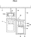
- 1 is a front view showing a transport vehicle and a part (fixed shelf) of a storage unit of a storage system according to a first embodiment of the present invention.
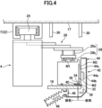
- FIG. 1 is a front view showing a part of a storage section equipped with a purging device provided in a storage system according to a first embodiment of the present invention.
- FIG. 1 is a schematic diagram showing a system configuration of a storage system according to a first embodiment of the present invention. 4 is a flowchart showing operations performed by the storage system according to the first embodiment of the present invention.
- FIG. 11 is a perspective view showing a storage system according to a second embodiment of the present invention.
- FIG. 11 is a perspective view showing a storage system according to a third embodiment of the present invention.
- the present invention is applied to a storage system that stores items such as FOUPs containing semiconductor wafers and reticle pods containing reticles in a clean room of a semiconductor manufacturing factory.
- Fig. 1 is a schematic plan view showing a transport system to which a storage system according to the first embodiment of the present invention is applied.
- a conveying system 1 to which the first embodiment of the present invention is applied includes a conveying vehicle 4 that conveys an article to be processed in a processing device 2, a plurality of buffers 6 that are temporary storage units for temporarily storing the article to be conveyed, a plurality of intrabay tracks 7 that can convey the article to the processing device 2, and an interbay track 8 that connects these intrabay tracks 7.
- the conveying system 1 includes a controller (not shown), which controls the conveying vehicle 4 to convey the article processed in the first processing device 2 to the buffer 6, and after the article is stored in the buffer 6, when a second processing device 2 that will perform the next process on the article is determined, conveys the article to the second processing device 2.
- the intrabay track 7 is a running track made up of rails installed on the ceiling, and multiple processing equipment 2 are arranged along this intrabay track 7 so that items can be transported to the processing equipment 2.
- the transport vehicle 4 travels while suspended from the intrabay track 7, and is therefore able to transport an item M from one processing equipment 2 arranged along the intrabay track 7 to another processing equipment 2.
- the transport vehicle 4 is a ceiling transport vehicle that travels along a running track installed on the ceiling.
- the transport system 1 also has multiple intrabay tracks 7, and the rails that make up each intrabay track 7 are suspended from the ceiling of the semiconductor manufacturing plant.
- the interbay track 8 is a running track made up of a circular rail suspended from the ceiling of the semiconductor manufacturing plant, and is connected to each intrabay track 6 via the branch track 7a. This allows the transport vehicles 2 provided in the transport system 1 to move from one intrabay track 6 to another intrabay track 6 via the interbay track 8. In other words, the transport system 1 can transport items M from a processing device 12 arranged along one intrabay track 6 to another processing device 12 arranged along another intrabay track 6.
- Fig. 2 is a perspective view showing the storage system according to the first embodiment of the present invention.
- a storage system 10 according to a first embodiment of the present invention includes the transport vehicle 4, which is the above-mentioned ceiling transport vehicle, and a storage facility 12 for storing items M.
- the storage facility 12 is equipped with multi-tier buffers 14 arranged on both sides (right and left sides in Figure 2) in the direction of travel of the transport vehicle 4.
- the multi-tier buffer 14 on one side (left side) has a fixed shelf 16, which serves as a storage section, on the top tier, and below this fixed shelf 16 are seven tiers of movable shelves 18 arranged vertically.
- the fixed shelves 16 are suspended from the ceiling 17 (see Figure 3) and are unable to move laterally (widthwise) themselves.
- the movable shelves 18 are also arranged on the floor surface 19, allowing items M to move laterally (widthwise) up to directly below the transport vehicle 4.
- the movable shelves 18 are for receiving and storing items M from the transport vehicle 4, and for transferring the stored items M to the transport vehicle 4, and therefore the movable shelves 18 are capable of moving laterally. For this reason, each level of the movable shelves 18 is provided with a movement mechanism 20 for moving the movable shelves 18 laterally.
- the moving mechanism 20 includes rails 20a extending laterally from the bottom of each movable shelf 18, rollers 20b attached to the movable shelf 18 and running on the rails 20a, and a drive motor 20c that rotates and drives the rollers 20b.
- the moving mechanism 20 moves the movable shelf 18 to directly below the transport vehicle 4, allowing the handover of items M between the movable shelf 18 and the transport vehicle 4.
- the multi-tier buffer 14 on the other side is similar to the right side, with a fixed shelf 16 that serves as a storage section at the top, and seven movable shelves 18 arranged vertically below the fixed shelf 16.
- the movable shelves 18 are also provided with a movement mechanism 20 for moving the movable shelves 18 laterally, and the movement mechanism 20 also has rails 20a, rollers 20b, and a drive motor 20c.
- Fig. 3 is a front view showing the transport vehicle and a part (fixed shelf) of the storage unit of the storage system according to the first embodiment.
- the transport vehicle 4 can travel to a target position by being suspended from rails 22 constituting the intrabay track 7 using a traveling mechanism 24.
- the transport vehicle 4 also includes a slide mechanism 26 and a gripping mechanism 28.
- the slide mechanism 26 can be extended and retracted horizontally by a ball screw drive mechanism (not shown), and a gripping mechanism 28 is attached to the tip thereof for gripping a flange M1 provided on the upper part of the article M.
- the gripping mechanism 28 also includes a suspension belt 28a and a gripper 28b.
- Four suspension belts 28a are provided for each transport vehicle 4, and are wound around a reel (not shown) provided at the tip of the slide mechanism 26.
- the gripper 28b has an opening and closing function that allows it to grip the flange M1 of the article M.
- the grippers 28b are suspended from four suspending belts 28a, and are adapted to move up and down via the suspending belts 28a by forward and reverse rotation of the reel by a driving device (not shown) such as a motor.
- the length of the suspending belts 28a is set so that the grippers 28b can grip the article M on the fixed shelf 16 and move it up and down.
- the grippers 28b are lowered to above the article M.
- the grippers 28b are opened and closed to hold the flange M1.
- the fixed shelf 16 is an overhead buffer (OHB) suspended from the ceiling 17 by a suspension rod 30 .
- the transport vehicle 4 travels on the intrabay track 7 and stops at a position opposite the multi-tier buffer 14, and unrolls the slide mechanism 26 toward the uppermost fixed shelf 16 of the multi-tier buffer 14. This moves the gripper 28b of the gripping mechanism 28 that is not gripping the item M to directly above the item M.
- the suspension belt 28a is extended, and the gripper 28b is lowered to above the specified item M in the fixed shelf 16, and the gripper 28b grips the flange M1 arranged on the item M.
- the reel (not shown) is rotated to wind up the suspension belt 28a, and the item M is raised together with the gripper 28b, and then the slide mechanism 26 is retracted.
- the movable shelf 18 is moved laterally inward by the moving mechanism 20, and the item M in the movable shelf 18 is moved to directly below the transport vehicle 4.
- the suspension belt 28a of the gripping mechanism 28 that is not gripping the item M is extended, and the gripper 28b is lowered to above the specified item M, and the gripper 28b grips the flange M1 arranged on the item M.
- the reel (not shown) is rotated to wind up the suspension belt 28a, and the item M is raised together with the gripper 28b to the transport vehicle 4.
- the moving mechanism 20 returns the movable shelf 18 from the position directly below the transport vehicle 4 to its original lateral position.
- the transport vehicle 4 carrying the item M travels along the intrabay track 7 and interbay track 8 toward the next destination of the item M.
- the loading operation of item M is as follows. First, when loading item M onto the fixed shelf 16, the loading operation is similarly performed in the reverse order to the unloading operation. That is, the transport vehicle 4, which has been traveling along the intrabay track 7 with item M gripped by the gripper 28b, stops at a predetermined position facing the fixed shelf 16 on which item M is to be loaded. Next, the slide mechanism 26 is unwound to move item M directly above the fixed shelf 16, and the suspension belt 28a is extended by rotating the reel (not shown), and the gripper 28b gripping item M is lowered to the height position of the fixed shelf 16 on which item M is to be loaded. Thereafter, the gripper 28b is released to load item M onto the fixed shelf 16.
- the placement work is similarly performed in the reverse order to the removal.
- the fixed shelf 18 is moved laterally inward by the moving mechanism 20, and the movable shelf 18 is moved to directly below the transport vehicle 4.
- the suspension belt 28a of the gripping mechanism 28 gripping item M is extended, and the gripper 28b gripping the item is lowered to the height position of the movable shelf 18.
- the gripper 28b is then released, and item M is placed on the movable shelf 18.
- the moving mechanism 20 then returns the movable shelf 18 from the position directly below the transport vehicle 4 to its original lateral position.
- Fig. 4 is a front view showing a part of a storage section equipped with the purging equipment provided in the storage system according to the first embodiment of the present invention.
- the article M is placed on the fixed shelf 16.
- the article M is a container for storing semiconductor wafers, reticles, etc.
- the fixed shelf 16 is provided with a purge facility 32 for supplying a purge gas to the article M.
- an opening M2 is formed on the side of the container (item M), and this opening M2 is closed by a lid M3.
- Semiconductor wafers and the like are stored inside the container (item M) through this opening M2.
- a purge gas inlet 34 and a purge gas outlet 36 are formed on the bottom surface of the container (item M).
- Check valves (not shown) are provided at the purge gas inlet 34 and outlet 36.
- the purge equipment 32 is equipment for supplying a purge gas into the container (item M).
- the purge gas is, for example, a gas such as nitrogen gas that is inert to the items stored in the container. Clean dry air, which is dry air, may also be used as the purge gas.
- the purge equipment 32 includes a purge nozzle 38 and an exhaust nozzle 40.
- the purge nozzle 38 and the exhaust nozzle 40 are provided on the upper surface of the fixed shelf 16.
- the purge nozzle 38 and the exhaust nozzle 40 are arranged so as to be connected to the purge gas inlet 34 and the purge gas outlet 36 of the container (item M), respectively, when the item M is placed on the movable shelf 16.
- the purge nozzle 38 is connected to a purge gas supply source via a pipe
- the exhaust nozzle 40 is connected to an exhaust path for the purge gas via a pipe.
- a suction device 42 is provided to prevent the leaked purge gas from accumulating near the lid M3.
- the suction device 42 includes a hood 44, which includes a wall 44a, a space 44b, and an opening 44c.
- a space 44b is formed inside the wall 44a, and this space 44b functions as a flow path for the sucked gas.
- the opening 44c opens toward the lid M3 of the container (item M) and serves as an inlet for the gas flow path inside the hood 44.
- An exhaust path 46 is connected to the outlet of the hood 44, and the sucked gas is exhausted from the opening 44c of the hood 44 through this exhaust path 46.
- a fan 48 is provided in the space 44b of the hood, and the gas is exhausted to the outside when the fan 48 is driven.
- Fig. 5 is a schematic diagram showing the system configuration of the storage system according to the first embodiment.
- the storage system 10 includes the transport vehicle 4 that travels on the intrabay track 9, and the multi-tier buffer 14 as the storage facility 12.
- the multi-tier buffer 14 includes a top fixed shelf 16 and multiple tiers of movable shelves 18 located below it.
- the fixed shelf 16 is provided with a purge facility 32 for supplying purge gas to the containers (items M).
- a manufacturing management system (MES) 50, a transport management system (MCS) 52, a purge controller 54, a transport vehicle controller 56, a fixed shelf control panel 58, and a movable shelf control panel 60 are provided as control devices for operating the storage system 10.
- MES manufacturing management system
- MCS transport management system
- purge controller 54 a transport vehicle controller
- transport vehicle controller 56 a fixed shelf control panel 58
- movable shelf control panel 60 movable shelf control panel
- the manufacturing management system (MES) 50 is a controller for managing production throughout the factory
- the transport management system (MCS) 52 is a controller for managing the transport of items M by transport vehicles
- the purge controller 54 is a controller for reporting the purging status and errors of the fixed shelves 16 to the transport management system (MCS) 52
- the transport vehicle controller 56 is a controller for providing information about the transport vehicles 2 to the movable shelves 18 of the multi-stage buffer 14
- the fixed shelf control panel 58 is a control panel for controlling the purging of the fixed shelves 16
- the movable shelf control panel 60 is a control panel for controlling the movement of the movable shelves 18. It is also possible to not provide the purge controller 54 and not report the purge status to the transport management system (MCS) 52.
- the manufacturing management system (MES) 50 determines which container (item M) in the fixed shelf 16 should receive the purge gas.
- Fig. 6 is a flow chart showing the operation performed by the storage system according to the first embodiment of the present invention.
- S indicates each step.
- S1 the transport vehicle 2 transports the article M.
- S2 the process proceeds to S2, where it is determined whether or not it is necessary to supply purge gas to the article M. If it is necessary to supply purge gas (YES), the process proceeds to S3.
- the topmost storage section of the storage equipment 12 is a fixed shelf 16 that cannot be moved back and forth laterally, and the storage sections other than the topmost section are movable shelves 18 that can be moved back and forth between a position advanced to directly below the ceiling track or transport vehicle 4 when viewed from above and a position retreated to the side from directly below the ceiling track or transport vehicle 4, and the storage equipment 12 further includes purging equipment 32 that supplies purging gas to the items M placed on the topmost fixed shelf 18.
- the movable shelves 18 are installed on the floor surface 19, and the fixed shelves 16 are suspended from the ceiling 17. Therefore, by installing the movable shelves 18 on the floor surface 19, the movable shelves 18 other than the topmost shelf can have a simple structure.
- the fixed shelf 16 is provided as the fixed storage section
- the movable shelf 18 is provided as the movable storage section, so that both storage sections can have a simple structure.
- FIG. 7 is a perspective view showing a storage system according to the second embodiment of the present invention.
- a storage system 70 according to the second embodiment of the present invention has the transport vehicle 4, which is the above-mentioned ceiling transport vehicle, and a storage facility 12 for storing items M.
- the storage facility 12 is equipped with multi-tier buffers 14 arranged on both sides (the right and left sides in FIG. 7) in the direction of travel of the transport vehicle 4.
- the multi-tier buffer 14 on one side (the right side) is equipped with a fixed shelf 16, which is a storage section, on the top tier, and two tiers of movable shelves 18 below the fixed shelf 16.
- the top tier fixed shelf 16 and the two tiers of movable shelves 18 are suspended from the ceiling 17 (see FIG. 3) by a suspension rod 72.
- the fixed shelf 16 is designed so that it cannot move laterally (widthwise) by itself, and the movable shelf 18 is designed so that the item M can move laterally (widthwise) to directly below the transport vehicle 4.
- the fixed shelf 16 is equipped with a purge facility 32 for supplying purge gas to the container (item M) as in the first embodiment described above.
- the movable shelves 18 are similar to those in the first embodiment and are used to receive and store items M from the transport vehicle 4, and to transfer the stored items M to the transport vehicle 4, and therefore the movable shelves 18 are capable of moving laterally. For this reason, each level of the movable shelves 18 is provided with a movement mechanism 20 for moving the movable shelves 18 laterally.
- the moving mechanism 20 includes rails 20a extending laterally from the bottom of each movable shelf 18, rollers 20b attached to the movable shelf 18 and running on the rails 20a, and a drive motor 20c that rotates and drives the rollers 20b.
- the moving mechanism 20 moves the movable shelf 18 to directly below the transport vehicle 4, allowing the handover of items M between the movable shelf 18 and the transport vehicle 4.
- the multi-tier buffer 14 on the other side is similar to the right side, with a fixed shelf 16 on the top tier, which is a storage section, and two tiers of movable shelves 18 below this fixed shelf 16.
- the top tier fixed shelf 16 and the two tiers of movable shelves 18 are suspended from the ceiling 17 (see Figure 3) by hanging rods 72.
- the fixed shelf 16 itself cannot move laterally (widthwise), and the movable shelf 18 is designed so that the item M can move laterally (widthwise) up to directly below the transport vehicle 4.
- the movable shelf 18 is also provided with a movement mechanism 20 for moving the movable shelf 18 laterally, and this movement mechanism 20 also has rails 20a, rollers 20b, and a drive motor 20c.
- the second embodiment provides the same advantageous effects as the first and third advantageous effects provided by the storage system according to the first embodiment described above.
- all of the fixed shelves 16 and movable shelves 18 that make up the multi-tiered storage section are suspended from the ceiling 17, making it possible to effectively utilize the space between the multi-tiered storage section and the floor surface 19.
- Fig. 8 is a perspective view showing a storage system according to the third embodiment of the present invention.
- a storage system 80 according to a third embodiment of the present invention has the transport vehicle 4, which is the above-mentioned ceiling transport vehicle, and a storage facility 12 for storing items M.
- the storage facility 12 is equipped with multi-tier buffers 14 arranged on both sides (right and left sides in FIG. 8) in the direction of travel of the transport vehicle 4.
- the multi-tier buffer 14 on one side (right side) is equipped with three tiers of movable shelves 18.
- the three tiers of movable shelves 18 are suspended from the ceiling 17 (see FIG. 3) by hanging rods 74.
- the movable shelves 18 are designed so that the items M can move laterally (widthwise) to directly below the transport vehicle 4.
- the fixed shelves 16 are equipped with purge equipment 32 for supplying purge gas to the containers (items M), as in the first embodiment described above.
- the movable shelves 18 are similar to those in the first embodiment and are used to receive and store items M from the transport vehicle 4, and to transfer the stored items M to the transport vehicle 4, and therefore the movable shelves 18 are capable of moving laterally. For this reason, each level of the movable shelves 18 is provided with a movement mechanism 20 for moving the movable shelves 18 laterally.
- the moving mechanism 20 includes rails 20a extending laterally from the bottom of each movable shelf 18, rollers 20b attached to the movable shelf 18 and running on the rails 20a, and a drive motor 20c that rotates and drives the rollers 20b.
- the moving mechanism 20 moves the movable shelf 18 to directly below the transport vehicle 4, allowing the handover of items M between the movable shelf 18 and the transport vehicle 4.
- the multi-tier buffer 14 on the other side is similar to the right side and has three tiers of movable shelves 18.
- the three tiers of movable shelves 18 are suspended from the ceiling 17 (see Figure 3) by hanging rods 74.
- the movable shelves 18 are designed so that the items M can move laterally (widthwise) to directly below the transport vehicle 4.
- the movable shelves 18 are also provided with a movement mechanism 20 for moving the movable shelves 18 laterally, and this movement mechanism 20 also has rails 20a, rollers 20b, and a drive motor 20c.
- a fixed shelf 16 is provided below these movable shelves 18 and directly below the transport vehicle 2. This fixed shelf 18 is suspended by the suspension rod 74 described above. The fixed shelf 18 itself cannot move laterally (widthwise).
- the third embodiment provides the same advantageous effects as the first and third advantageous effects provided by the storage system according to the first embodiment described above.
- all of the fixed shelves 16 and movable shelves 18 that make up the multi-tiered storage section are suspended from the ceiling 17, making it possible to effectively utilize the space between the multi-tiered storage section and the floor surface 19.
- Transport system 4 Transport vehicle 6 Buffer 7 Intra-bay track 8 Inter-bay track 10, 70, 80 Storage system 12 Storage facility 14 Multi-stage buffer 16, 82 Fixed shelf 17 Ceiling 18 Movable shelf 19 Floor surface 20 Moving mechanism 20a Rail 20b Roller 20c Drive motor 22 Rail 24 Travel mechanism 26 Slide mechanism 28 Grip mechanism 30, 72, 74 Suspension rod 32 Purge facility 34 Inlet 36 Outlet 38 Purge nozzle 40 Exhaust nozzle 50 Manufacturing management device 52 Transport management device 54 Purge controller 56 Transport vehicle controller 58 Fixed shelf control panel 60 Movable shelf control panel M Item
Landscapes
- Engineering & Computer Science (AREA)
- Mechanical Engineering (AREA)
- Warehouses Or Storage Devices (AREA)
Abstract
Description
ラックが上下方向に複数段配置される場合には、全ての段のラックに物品を天井自走車の真下まで移動させる可動式の棚板が設けられている。しかしながら、棚板が可動式の場合には、パージ用の配管を設けるための機構が複雑となり、設計上の問題が生じ、困難な場合がある。
このように構成された本発明においては、保管設備の最上段の保管部は、側方への進退が不能な固定保管部であり、最上段以外の保管部は、上面視で天井軌道の真下に進出した位置と天井軌道の真下から側方に待避した位置との間で進退可能な可動保管部であり、保管設備は、さらに、最上段の固定保管部に載置された物品にパージガスを供給するパージ設備を備えているので、保管部を上下方向に複数段配置した場合であっても、パージ設備により、パージガスを最上段の固定保管部に供給すればよいので、パージ用の配管等の配置を簡単化することができ、極めて実用的な保管システムとなる。
このように構成された本発明においては、可動保管部は床面に設置され、固定保管部は天井から吊り下げられているので、可動保管部が床面に設置されることにより、最上段以外の可動保管部を簡易な構造とすることができる。
このように構成された本発明においては、複数段の保管部の全てが天井から吊り下げられているので、複数段の保管部と床面との間の空間を有効に利用することができる。
このように構成された本発明においては、固定保管部は固定棚を備え、可動保管部は可動棚を備えているので、両保管部を簡易な構造とすることができる。
先ず、図1乃至図3により、本発明の第1実施形態による保管システムの基本構造について説明する。
なお、本実施形態においては、半導体製造工場のクリーンルーム内において、半導体ウェハを収容したフープ(FOUP)や、レクチルを収容したレチクルポッド(Reticle Pod)等の物品を保管する保管システムに、本発明が適用されている。
図1に示すように、本発明の第1実施形態が適用される搬送システム1は、処理装置2おいて処理すべき物品を搬送する搬送車4と、搬送すべき物品を一時的に保管する複数の一時保管部であるバッファ6と、処理装置2に物品を搬送することができる複数のイントラベイ軌道7と、これらのイントラベイ軌道7を接続するインターベイ軌道8と、を有する。さらに、搬送システム1はコントローラ(図示せず)を有し、コントローラは、搬送車4を制御して、第1の処理装置2において処理された物品をバッファ6に搬送すると共に、このバッファ6に物品が保管された後で、その物品に対して次工程の処理を行う第2の処理装置2が決定されると、物品を第2の処理装置2に搬送する。
図2に示すように、本発明の第1実施形態による保管システム10は、上述した天井搬送車である搬送車4と、物品Mを保管する保管設備12を有する。
図3に示すように、搬送車4は、イントラベイ軌道7を構成するレール22から吊り下げられた状態で、走行機構24により走行し、目標となる位置まで移動することができる。また、搬送車4は、スライド機構26及び把持機構28を備えている。
懸垂ベルト28aは、1つの搬送車4に4本備えられており、スライド機構26の先端に設けられたリール(図示せず)に巻回している。また、グリッパ28bは、物品MのフランジM1を狭持可能な開閉機能を有している。
さらに、図3に示すように、固定棚16は、吊下ロッド30により天井17から吊り下げられたオーバーヘッドバッファ(OHB)である。
物品Mの搬出動作は以下のようになる。先ず、固定棚16内の物品Mを搬出する場合、イントラベイ軌道7を走行し、多段バッファ14の対向位置に停止した搬送車4は、多段バッファ14の最上段の固定棚16へ向けてスライド機構26を繰り出す。これにより物品Mを把持していない把持機構28のグリッパ28bを物品Mの真上まで移動させる。目的とする物品Mの真上までグリッパ28bを移動させた後、懸垂ベルト28aを伸張させ、固定棚16内の所定の物品Mの上までグリッパ28bを降下させて、グリッパ28bで物品Mに配設されたフランジM1を把持する。次いで、物品Mを把持した後、リール(図示せず)を回転させることで懸垂ベルト28aを巻き上げ、グリッパ28bと共に物品Mを上昇させ、続いてスライド機構26を縮退させる。
図4に示すように、固定棚16には、物品Mが載置されている。この物品Mは、上述したように、半導体ウェハやレチクルなどを収納する容器である。固定棚16には、物品Mにパージガスを供給するためのパージ設備32が設けられている。
パージ設備32は、パージノズル38及び排気ノズル40を備えている。これらのパージノズル38及び排気ノズル40は、固定棚16の上面に設けられている。また、パージノズル38及び排気ノズル40は、可動棚16に物品Mを載置した際に、それぞれ、容器(物品M)のパージガスの導入口34とパージガスの排出口36と接続するように配置されている。パージノズル38は、配管を介してパージガス供給源に接続され、排気ノズル40は、配管を介してパージガスの排気経路に接続されている。
そのため、本実施形態においては、図4に示すように、吸引装置42を設け、漏れたパージガスが蓋M3の近傍に滞留するのを抑制するようにしている。
保管システム10は、上述したように、イントラベイ軌道9を走行する搬送車4と、保管設備12として多段バッファ14を備えている。多段バッファ14は、最上段の固定棚16と、その下方に位置する複数段の可動棚18を備えている。固定棚16には、容器(物品M)にパージガスを供給するためのパージ設備32が設けられている。
本実施形態においては、これらの制御機器より、多段バッファ14の固定棚16に物品Mが載置されたとき、容器(物品M)にパージガスがパージされるようになっている。
なお、パージコントローラ54を設けることなく、搬送管理装置(MCS)52にパージの状況等を報告しないようにしてもよい。また、固定棚16において、どの容器(物品M)にパージガスを供給するかは、製造管理装置(MES)50により判断される。
最初に、S1において、搬送車2により物品Mを搬送する。次に、S2に進み、物品Mへのパージガスの供給が必要か否かを判断する。パージガスの供給が必要な場合(YES)には、S3に進む。
一方、S2において、物品Mへのパージガスの供給は不要である(NO)と判断された場合には、S5に進む。S5において、最上段以外の可動棚18へ物品Mを載置する。
第1に、第1実施形態においては、保管設備12の最上段の保管部は、側方への進退が不能な固定棚16であり、最上段以外の保管部は、上面視で天井軌道又は搬送車4の真下に進出した位置と天井軌道又は搬送車4の真下から側方に待避した位置との間で進退可能な可動棚18であり、保管設備12は、さらに、最上段の固定棚18に載置された物品Mにパージガスを供給するパージ設備32を備えているので、保管部を上下方向に複数段配置した場合であっても、パージ設備32により、パージガスを最上段の固定棚16に供給すればよいので、パージ用の配管等の配置を簡単化することができ、極めて実用的な保管システムとなる。
第3に、第1実施形態においては、固定保管部として固定棚16を備え、可動保管部として可動棚18を備えているので、両保管部を簡易な構造とすることができる。
図7に示すように、本発明の第2実施形態による保管システム70は、上述した天井搬送車である搬送車4と、物品Mを保管する保管設備12を有する。
第1に、第2実施形態においては、上述した第1実施形態による保管システムが奏する第1及び第3の作用効果と同様な作用効果を奏する。
図8に示すように、本発明の第3実施形態による保管システム80は、上述した天井搬送車である搬送車4と、物品Mを保管する保管設備12を有する。
第1に、第3実施形態においては、上述した第1実施形態による保管システムが奏する第1及び第3の作用効果と同様な作用効果を奏する。
4 搬送車
6 バッファ
7 イントラベイ軌道
8 インターベイ軌道
10、70、80 保管システム
12 保管設備
14 多段バッファ
16、82 固定棚
17 天井
18 可動棚
19 床面
20 移動機構
20a レール
20b ローラ
20c 駆動モータ
22 レール
24 走行機構
26 スライド機構
28 把持機構
30、72、74 吊下ロッド
32 パージ設備
34 導入口
36 排出口
38 パージノズル
40 排気ノズル
50 製造管理装置
52 搬送管理装置
54 パージコントローラ
56 搬送車コントローラ
58 固定棚制御盤
60 可動棚制御盤
M 物品
Claims (6)
- 天井軌道を走行して物品を搬送する天井搬送車と、天井軌道の下方且つ側方に位置し、天井搬送車から物品を受け取って保管する保管設備と有する保管システムであって、
上記天井搬送車は搭載する物品を側方に移動させるための側方移動用装置を備え、
上記保管設備は、上下方向に配置された複数段の保管部を備え、
この保管設備の最上段の保管部は、側方への進退が不能な固定保管部であり、最上段以外の保管部は、上面視で天井軌道の真下に進出した位置と天井軌道の真下から側方に待避した位置との間で進退可能な可動保管部であり、
上記保管設備は、さらに、上記最上段の固定保管部に載置された物品にパージガスを供給するパージ設備を備えている、保管システム。 - 上記可動保管部は床面に設置され、上記固定保管部は天井から吊り下げられている、請求項1に記載の保管システム。
- 上記複数段の保管部の全てが天井から吊り下げられている、請求項1に記載の保管システム。
- 上記固定保管部は固定棚を備え、上記可動保管部は可動棚を備える、請求項1に記載の保管システム。
- さらに、物品を保管すべき保管部を指定してこの保管部への物品の移載を天井搬送車に指示するコントローラを備え、
このコントローラは、物品へのパージガスの供給が必要であると判断する場合に、最上段の固定保管部への上記物品の移載を天井搬送車に指示し、物品へのパージガスの供給が不要であると判断する場合に、最上段以外の可動保管部への上記物品の移載を天井搬送車に指示する、請求項1乃至4の何れか1項に記載の保管システム。 - 天井軌道を走行して物品を搬送する天井搬送車と、天井軌道の下方且つ側方に位置し、天井搬送車から物品を受け取って保管する保管設備と有する保管システムであって、
上記保管設備は、上下方向に配置された複数の第1保管部、及び、これらの複数の保管部の下方で且つ上記天井軌道の真下に固定配置された第2保管部を備え、
上記保管設備の第1保管部は、上面視で天井軌道の真下に進出した位置と天井軌道の真下から側方に待避した位置との間で進退可能な可動保管部であり、
上記保管設備は、さらに、上記第2保管部に載置された物品にパージガスを供給するパージ設備を備えている、保管システム。
Priority Applications (3)
| Application Number | Priority Date | Filing Date | Title |
|---|---|---|---|
| CN202480035325.5A CN121359627A (zh) | 2023-06-13 | 2024-05-24 | 保管系统 |
| DE112024002540.4T DE112024002540T5 (de) | 2023-06-13 | 2024-05-24 | Lagersystem |
| JP2025527615A JPWO2024257583A1 (ja) | 2023-06-13 | 2024-05-24 |
Applications Claiming Priority (2)
| Application Number | Priority Date | Filing Date | Title |
|---|---|---|---|
| JP2023097060 | 2023-06-13 | ||
| JP2023-097060 | 2023-06-13 |
Publications (1)
| Publication Number | Publication Date |
|---|---|
| WO2024257583A1 true WO2024257583A1 (ja) | 2024-12-19 |
Family
ID=93851837
Family Applications (1)
| Application Number | Title | Priority Date | Filing Date |
|---|---|---|---|
| PCT/JP2024/019148 Ceased WO2024257583A1 (ja) | 2023-06-13 | 2024-05-24 | 保管システム |
Country Status (5)
| Country | Link |
|---|---|
| JP (1) | JPWO2024257583A1 (ja) |
| CN (1) | CN121359627A (ja) |
| DE (1) | DE112024002540T5 (ja) |
| TW (1) | TW202502639A (ja) |
| WO (1) | WO2024257583A1 (ja) |
Citations (5)
| Publication number | Priority date | Publication date | Assignee | Title |
|---|---|---|---|---|
| JP2013142009A (ja) * | 2012-01-06 | 2013-07-22 | Daifuku Co Ltd | 物品保管設備 |
| WO2015046062A1 (ja) * | 2013-09-30 | 2015-04-02 | 株式会社日立国際電気 | 基板処理装置、半導体装置の製造方法および記録媒体 |
| JP2016066689A (ja) * | 2014-09-24 | 2016-04-28 | 東京エレクトロン株式会社 | 容器清掃装置及び容器清掃方法 |
| WO2017212841A1 (ja) * | 2016-06-08 | 2017-12-14 | 村田機械株式会社 | 容器保管装置及び容器保管方法 |
| JP2021077691A (ja) * | 2019-11-06 | 2021-05-20 | 東京エレクトロン株式会社 | 基板処理装置及び基板収納容器保管方法 |
Family Cites Families (1)
| Publication number | Priority date | Publication date | Assignee | Title |
|---|---|---|---|---|
| JPH06104554B2 (ja) | 1986-06-13 | 1994-12-21 | 村田機械株式会社 | 天井自走車 |
-
2024
- 2024-05-24 CN CN202480035325.5A patent/CN121359627A/zh active Pending
- 2024-05-24 DE DE112024002540.4T patent/DE112024002540T5/de active Pending
- 2024-05-24 JP JP2025527615A patent/JPWO2024257583A1/ja active Pending
- 2024-05-24 WO PCT/JP2024/019148 patent/WO2024257583A1/ja not_active Ceased
- 2024-06-04 TW TW113120553A patent/TW202502639A/zh unknown
Patent Citations (5)
| Publication number | Priority date | Publication date | Assignee | Title |
|---|---|---|---|---|
| JP2013142009A (ja) * | 2012-01-06 | 2013-07-22 | Daifuku Co Ltd | 物品保管設備 |
| WO2015046062A1 (ja) * | 2013-09-30 | 2015-04-02 | 株式会社日立国際電気 | 基板処理装置、半導体装置の製造方法および記録媒体 |
| JP2016066689A (ja) * | 2014-09-24 | 2016-04-28 | 東京エレクトロン株式会社 | 容器清掃装置及び容器清掃方法 |
| WO2017212841A1 (ja) * | 2016-06-08 | 2017-12-14 | 村田機械株式会社 | 容器保管装置及び容器保管方法 |
| JP2021077691A (ja) * | 2019-11-06 | 2021-05-20 | 東京エレクトロン株式会社 | 基板処理装置及び基板収納容器保管方法 |
Also Published As
| Publication number | Publication date |
|---|---|
| TW202502639A (zh) | 2025-01-16 |
| JPWO2024257583A1 (ja) | 2024-12-19 |
| DE112024002540T5 (de) | 2026-04-09 |
| CN121359627A (zh) | 2026-01-16 |
Similar Documents
| Publication | Publication Date | Title |
|---|---|---|
| KR102076630B1 (ko) | 물품 보관 설비 및 물품 반송 설비 | |
| US20250304374A1 (en) | Storage system | |
| US11978652B2 (en) | Automatic handling buffer for bare stocker | |
| US9701431B2 (en) | Load port device, transport system, and container carrying out method | |
| US6468021B1 (en) | Integrated intra-bay transfer, storage, and delivery system | |
| TWI722208B (zh) | 搬送系統 | |
| US8374719B2 (en) | Article processing facility and its control method | |
| JP4123383B2 (ja) | 天井走行車システム | |
| US20120093620A1 (en) | Stocker | |
| KR101414530B1 (ko) | 반송차 시스템 | |
| KR101511963B1 (ko) | 카세트 공급시스템 | |
| JP6455404B2 (ja) | 容器搬送設備 | |
| TW201634363A (zh) | 在天花板上存儲和處理物品的裝置 | |
| US11460766B2 (en) | Article storage facility | |
| CN108290687B (zh) | 保管装置以及输送系统 | |
| WO2019021708A1 (ja) | 自動倉庫システム、及び自動倉庫システムの制御方法 | |
| JP4126559B2 (ja) | 天井走行車システム | |
| JP2008174357A (ja) | ストッカ | |
| JPH11157606A (ja) | 自動搬送装置を備えた冷凍庫設備 | |
| CN121359627A (zh) | 保管系统 | |
| JP2611747B2 (ja) | ウエハ収納箱搬送装置 | |
| KR20100113625A (ko) | 베어 스토커용 자동 취급 버퍼 | |
| HK40097177A (zh) | 储存系统以及在储存系统中整合多个物品的方法 | |
| KR20190052875A (ko) | 카세트 공급시스템 | |
| JP2002060007A (ja) | 搬送システム |
Legal Events
| Date | Code | Title | Description |
|---|---|---|---|
| 121 | Ep: the epo has been informed by wipo that ep was designated in this application |
Ref document number: 24823204 Country of ref document: EP Kind code of ref document: A1 |
|
| ENP | Entry into the national phase |
Ref document number: 2025527615 Country of ref document: JP Kind code of ref document: A |
|
| WWE | Wipo information: entry into national phase |
Ref document number: 2025527615 Country of ref document: JP |
|
| WWE | Wipo information: entry into national phase |
Ref document number: 112024002540 Country of ref document: DE |
|
| WWP | Wipo information: published in national office |
Ref document number: 112024002540 Country of ref document: DE |