WO2024257560A1 - 制御システム、制御装置、制御方法、制御プログラム - Google Patents
制御システム、制御装置、制御方法、制御プログラム Download PDFInfo
- Publication number
- WO2024257560A1 WO2024257560A1 PCT/JP2024/018613 JP2024018613W WO2024257560A1 WO 2024257560 A1 WO2024257560 A1 WO 2024257560A1 JP 2024018613 W JP2024018613 W JP 2024018613W WO 2024257560 A1 WO2024257560 A1 WO 2024257560A1
- Authority
- WO
- WIPO (PCT)
- Prior art keywords
- autonomous
- posture
- control
- transport device
- power generation
- Prior art date
- Legal status (The legal status is an assumption and is not a legal conclusion. Google has not performed a legal analysis and makes no representation as to the accuracy of the status listed.)
- Ceased
Links
Images




Classifications
-
- B—PERFORMING OPERATIONS; TRANSPORTING
- B60—VEHICLES IN GENERAL
- B60L—PROPULSION OF ELECTRICALLY-PROPELLED VEHICLES; SUPPLYING ELECTRIC POWER FOR AUXILIARY EQUIPMENT OF ELECTRICALLY-PROPELLED VEHICLES; ELECTRODYNAMIC BRAKE SYSTEMS FOR VEHICLES IN GENERAL; MAGNETIC SUSPENSION OR LEVITATION FOR VEHICLES; MONITORING OPERATING VARIABLES OF ELECTRICALLY-PROPELLED VEHICLES; ELECTRIC SAFETY DEVICES FOR ELECTRICALLY-PROPELLED VEHICLES
- B60L15/00—Methods, circuits, or devices for controlling the traction-motor speed of electrically-propelled vehicles
- B60L15/20—Methods, circuits, or devices for controlling the traction-motor speed of electrically-propelled vehicles for control of the vehicle or its driving motor to achieve a desired performance, e.g. speed, torque, programmed variation of speed
-
- B—PERFORMING OPERATIONS; TRANSPORTING
- B60—VEHICLES IN GENERAL
- B60L—PROPULSION OF ELECTRICALLY-PROPELLED VEHICLES; SUPPLYING ELECTRIC POWER FOR AUXILIARY EQUIPMENT OF ELECTRICALLY-PROPELLED VEHICLES; ELECTRODYNAMIC BRAKE SYSTEMS FOR VEHICLES IN GENERAL; MAGNETIC SUSPENSION OR LEVITATION FOR VEHICLES; MONITORING OPERATING VARIABLES OF ELECTRICALLY-PROPELLED VEHICLES; ELECTRIC SAFETY DEVICES FOR ELECTRICALLY-PROPELLED VEHICLES
- B60L8/00—Electric propulsion with power supply from forces of nature, e.g. sun or wind
-
- G—PHYSICS
- G05—CONTROLLING; REGULATING
- G05D—SYSTEMS FOR CONTROLLING OR REGULATING NON-ELECTRIC VARIABLES
- G05D1/00—Control of position, course, altitude or attitude of land, water, air or space vehicles, e.g. using automatic pilots
- G05D1/40—Control within particular dimensions
- G05D1/43—Control of position or course in two dimensions [2D]
-
- G—PHYSICS
- G05—CONTROLLING; REGULATING
- G05D—SYSTEMS FOR CONTROLLING OR REGULATING NON-ELECTRIC VARIABLES
- G05D1/00—Control of position, course, altitude or attitude of land, water, air or space vehicles, e.g. using automatic pilots
- G05D1/40—Control within particular dimensions
- G05D1/49—Control of attitude, i.e. control of roll, pitch or yaw
-
- H—ELECTRICITY
- H02—GENERATION; CONVERSION OR DISTRIBUTION OF ELECTRIC POWER
- H02J—ELECTRIC POWER NETWORKS; CIRCUIT ARRANGEMENTS OR SYSTEMS FOR SUPPLYING OR DISTRIBUTING ELECTRIC POWER; SYSTEMS FOR STORING ELECTRIC ENERGY
- H02J1/00—Circuit arrangements for DC mains or DC distribution networks
Definitions
- This disclosure relates to technology for controlling the autonomous travel of an autonomous transport device.
- Patent Document 1 searches for future routes with high levels of sunlight irradiation for vehicles equipped with solar cells as power generation units that generate electricity from sunlight.
- Patent Document 2 determines a future route for an autonomous transport device that transports items that require refrigeration, in which the temperature of the transport environment will decrease, based on the results of a simulation of sunlight incidence.
- Patent Document 1 if the technology disclosed in Patent Document 1 is used in a device equipped with a solar power generation unit as an autonomous transport device that transports items that require refrigeration, the temperature of the transport environment will increase on the future route. Conversely, if the technology disclosed in Patent Document 2 is used in a device equipped with a solar power generation unit as an autonomous transport device that transports items that require refrigeration, the amount of sunlight irradiation will decrease on the future route.
- the object of this disclosure is to provide a control system that conserves energy. Another object of this disclosure is to provide a control device that conserves energy. Yet another object of this disclosure is to provide a control method that conserves energy. Yet another object of this disclosure is to provide a control program that conserves energy.
- a first aspect of the present disclosure is A control system for controlling the autonomous travel of an autonomous transport device that has a processor and receives power from a power generation unit that receives sunlight and generates power in order to store an item requiring refrigeration in a transport chamber and transport the item by autonomous travel, comprising: The processor Obtaining incidence information regarding incidence of sunlight on the autonomous transport device; The system is configured to adjust the running posture of the autonomous transport device during autonomous traveling to a control posture that positions the transport chamber in a direction opposite to the sun direction with respect to the light receiving surface that is oriented in the sun direction in accordance with incident information to receive sunlight in the power generation unit.
- a second aspect of the present disclosure is A control device having a processor, configured to be mountable on an autonomous transport device that receives power from a power generation unit that generates power by receiving sunlight, in order to store an item requiring refrigeration in a transport chamber and transport the item by autonomous transport, and that controls the autonomous transport device,
- the processor Obtaining incidence information regarding incidence of sunlight on the autonomous transport device;
- the system is configured to adjust the running posture of the autonomous transport device during autonomous traveling to a control posture that positions the transport chamber in a direction opposite to the sun direction with respect to the light receiving surface that is oriented in the sun direction in accordance with incident information to receive sunlight in the power generation unit.
- a third aspect of the present disclosure is A control method executed by a processor, in which an autonomous transport device receives power from a power generation unit that receives sunlight and generates power in order to store an item requiring refrigeration in a transport chamber and transport the item by autonomous transport, comprising: Obtaining incidence information regarding incidence of sunlight on the autonomous transport device; This includes adjusting the traveling posture of the autonomous transport device during autonomous traveling to a controlled posture that positions the transport chamber in a direction opposite to the sun direction with respect to the light receiving surface that is oriented in the sun direction in accordance with incident information to receive sunlight in the power generation unit.
- a fourth aspect of the present disclosure is A control program stored in a storage medium includes instructions to be executed by a processor that controls autonomous travel of an autonomous transport device that receives power from a power generation unit that generates power by receiving sunlight in order to store an item requiring refrigeration in a transport chamber and transport the item by autonomous travel, Obtaining incidence information regarding incidence of sunlight on the autonomous transport device;
- the control posture of the autonomous transport device during autonomous travel is adjusted to a control posture that positions the transport chamber in a direction opposite to the sun direction with respect to the light receiving surface that is oriented in the sun direction according to incident information to receive sunlight in the power generation unit.
- the autonomous transport device in order to store items requiring refrigeration in a transport chamber and transport them by autonomous travel, the autonomous transport device is controlled to receive power from a power generation unit that receives sunlight and generates power, and the autonomous transport device's autonomous travel is controlled.
- incident information regarding the incidence of sunlight on the autonomous transport device is acquired, and the travel posture of the autonomous transport device during autonomous travel is adjusted according to the incident information.
- the travel posture is adjusted to a control posture that positions the transport chamber in the opposite direction to the sun direction, relative to the light receiving surface of the power generation unit that is oriented in the sun direction to receive sunlight according to the incident information. In this way, it is possible to ensure power generation efficiency in the power generation unit whose light receiving surface faces the sun direction, while ensuring cooling efficiency for items in the transport chamber that is oriented in the opposite direction to the sun direction relative to the light receiving surface, thereby saving energy.
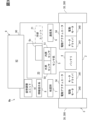
- FIG. 2 is a block diagram showing the physical configuration of the control system according to the first embodiment.
- 1 is a perspective view showing a physical configuration of an autonomous driving device to which a first embodiment is applied.
- 1 is a block diagram showing a functional configuration of an autonomous driving device to which a first embodiment is applied.
- FIG. 2 is a block diagram showing a functional configuration of the control system according to the first embodiment.
- 4 is a flowchart showing a control flow according to the first embodiment.
- FIG. 4 is a schematic diagram for explaining a control attitude according to the first embodiment.
- FIG. 4 is a schematic diagram for explaining a control attitude according to the first embodiment.
- 1 is a graph for explaining cold insulation efficiency according to the first embodiment.
- 1 is a graph for explaining cold insulation efficiency according to the first embodiment.
- 10 is a flowchart showing a control flow according to a second embodiment.
- 13 is a flowchart showing a control flow according to a third embodiment.
- 13 is a flowchart showing a control flow according to a third embodiment.
- 13 is a graph for explaining the determination of an optimum route according to the third embodiment.
- the control system 1 of the first embodiment shown in FIG. 1 controls the autonomous travel of an autonomous transport device Ma that stores an item Gc in a transport chamber 20 and transports it by autonomous travel, as shown in FIGS. 2 and 3.
- the autonomous transport device Ma is constructed so that it can travel autonomously in any direction along a horizontal plane.
- the autonomous transport device Ma transports items Gc that require refrigeration.
- the items Gc that require refrigeration may be, for example, at least one type of food among refrigerated items, frozen items, and items stored at room temperature.
- the items Gc that require refrigeration may be at least one type of items other than food, such as medicines, feed, solvents, solutions, miscellaneous items, building materials, and electronic devices.
- Such items Gc that require refrigeration may be loaded into the transport chamber 20 in a state where they are packed or wrapped in, for example, at least one type of cardboard box, polystyrene foam case, plastic case, plastic film, and the like.
- the autonomous transport device Ma may transport items Gc that do not require refrigeration, as long as it is constructed to be able to transport items Gc that require refrigeration.
- the autonomous transport device Ma may be a delivery vehicle or a delivery robot that autonomously travels on a travel path (i.e., a road) on an external route as a travel area, or on a travel path inside and outside a building in a smart city as a travel area, to deliver luggage as the item Gc.
- the autonomous transport device Ma may be a transport vehicle or a transport robot that autonomously travels on a travel path inside and outside a warehouse in a logistics facility as a travel area to transport luggage as the item Gc.
- the autonomous transport device Ma may be a food delivery robot that autonomously travels on a travel path in a restaurant or hospital as a travel area to deliver food and drink as the item Gc.
- the autonomous transport device Ma may be a disaster support robot that autonomously travels while searching for a travel path that can be traveled in a disaster area as a travel area, to transport supplies as the item Gc.
- the autonomous transport device Ma may of course be a device other than these.
- any type of autonomous transport device Ma may receive remote travel support or travel control from an external center.
- the autonomous transport device Ma includes a body 2, a drive system 3, a battery 4, a sensor system 5, a communication system 6, a map database 7, and an information presentation system 8.
- the body 2 is hollow and made of, for example, metal.
- the body 2 holds other components of the autonomous transport device Ma inside or across from the inside to the outside.
- the body 2 forms a transport chamber 20 to accommodate the goods Gc loaded from the outside onto the autonomous transport device Ma as the transport target.
- the transport chamber 20 may be configured to exhibit refrigeration performance for the goods Gc by being surrounded in a box shape by walls made of insulating material, for example as the internal space of a refrigerated container.
- the transport chamber 20 may be configured to be able to keep the goods Gc cool at or below a set temperature by the cooling function of a cooling unit 21 (see the two-dot chain line in Figure 3) mounted on the body 2.
- the cooling unit 21 may be an air conditioning unit that adjusts the air conditioning temperature of the transport chamber 20, or a refrigeration unit that refrigerates (or freezes) the goods Gc in the transport chamber 20.
- the drive system 3 includes wheels 30 and an electric actuator 34.
- a number of wheels 30 are supported by the body 2.
- Each wheel 30 is configured to be able to rotate independently.
- a pair of drive wheels 300 are each driven independently by a separate electric actuator 34.
- the running state of the autonomous transport device Ma is switched between straight running and turning running depending on the difference in rotational speed (i.e., the difference in the number of rotations per unit time) between these drive wheels 300.
- the autonomous transport device Ma is driven in a straight line.
- the turning radius of the autonomous transport device Ma when it is turned decreases in accordance with the increase in the rotational speed difference.
- the turning radius means the distance in a plan view between the vertical center line of the body 2 and the turning center of the turning drive, so turning drive in which the turning radius is effectively reduced to zero is point turning drive.
- the multiple wheels 30 may include at least one driven wheel that rotates following the driving wheel 300.
- At least one battery 4 shown in FIG. 3 is mounted on the body 2.
- the battery 4 is mainly composed of a storage battery such as a lithium ion battery.
- the battery 4 stores output power from the power generation unit 9 as power to be supplied to the electrical equipment in the body 2 by discharging.
- the battery 4 may store power to be supplied to the electrical equipment in the body 2 by discharging by charging from an external source.
- the battery 4 may store regenerated power from the electric actuator 34.
- the battery 4 is connected to the electric actuator 34, the sensor system 5, the communication system 6, the map database 7, the information presentation system 8, and the power generation unit 9, which are the destinations of the power supply, via a wire harness so that it can supply power.
- the battery 4 may also be connected to the cooling unit 21, when mounted on the body 2, via a wire harness so that it can supply power.
- a pair of electric actuators 34 are supported by the body 2.
- Each electric actuator 34 one on each side of the body 2, is mainly composed of an electric motor 340 and a motor driver 341.
- the electric motor 340 drives and rotates the corresponding drive wheel 300 independently.
- the motor driver 341 adjusts the current applied to the electric motor 340 of the same pair according to a current command value from the control system 1, thereby controlling the output of drive torque to the corresponding drive wheel 300 according to the current command value.
- Each electric actuator 34 may be equipped with a brake unit that applies braking to the corresponding drive wheel 300 while it is rotating.
- the sensor system 5 shown in Figures 2 and 3 acquires sensing information that can be used by the control system 1 by sensing the external and internal worlds of the autonomous transport device Ma. To that end, the components of the sensor system 5 are mounted in multiple locations on the body 2. Specifically, the sensor system 5 is composed of an external sensor 50 and an internal sensor 51.
- the external sensor 50 acquires external information as sensing information from the external world that is the surrounding environment of the autonomous transport device Ma.
- the external sensor 50 acquires external information by detecting objects that exist in the external world of the autonomous transport device Ma.
- the object detection type external sensor 50 is at least one of the following types: a camera, LiDAR (Light Detection and Ranging/Laser Imaging Detection and Ranging), radar, sonar, an ambient light sensor, and an impact sensor.
- the internal sensor 51 shown in FIG. 3 acquires internal information as sensing information from the internal world, which is the internal environment of the autonomous transport device Ma.
- the internal sensor 51 may be a physical quantity detection type that acquires internal information by detecting a specific physical quantity of motion in the internal world of the autonomous transport device Ma.
- the physical quantity detection type internal sensor 51 is at least one type of sensor, such as a speed sensor, an acceleration sensor, or an inertial sensor.
- the internal sensor 51 may be an indoor detection type that acquires internal information by detecting the inside of the transport chamber 20, which is the internal world of the autonomous transport device Ma.
- the indoor detection type internal sensor 51 is at least one type of sensor, such as a temperature sensor, a weight sensor, a pressure sensor, a camera, or an RFID (Radio Frequency Identifier) reader.
- the communication system 6 transmits and receives communication information usable by the control system 1 via wireless communication between the autonomous transport device Ma and the outside world.
- the communication system 6 may be of a positioning type that acquires communication information by receiving positioning signals from artificial satellites of the Global Navigation Satellite System (GNSS) that exist in the outside world of the autonomous transport device Ma.
- GNSS Global Navigation Satellite System
- the positioning type communication system 6 is, for example, a GNSS receiver.
- the communication system 6 may be of a V2X type that transmits and receives communication information between the autonomous transport device Ma and a V2X system that exists outside the autonomous transport device Ma.
- the V2X type communication system 6 is, for example, at least one of a Dedicated Short Range Communications (DSRC) communication device and a Cellular V2X (C-V2X) communication device.
- the communication system 6 may be of a terminal communication type that transmits and receives communication information between the autonomous transport device Ma and a mobile terminal that exists outside the autonomous transport device Ma.
- the terminal communication type communication system 6 is, for example, at least one of a Bluetooth (registered trademark) device, a Wi-Fi (registered trademark) device, and an infrared communication device.
- the map database 7 stores map information that can be used by the control system 1.
- the map database 7 includes at least one type of non-transitory tangible storage medium, such as a semiconductor memory, a magnetic medium, or an optical medium.
- the map database 7 may be a database of a locator that estimates the self-position of the autonomous transport device Ma.
- the map database 7 may be a database of a planning unit that plans the travel of the autonomous transport device Ma.
- the map database 7 may be composed of a combination of multiple types of these databases.
- the map database 7 acquires and stores the latest map information, for example, by communication with an external center.
- the map information is digitized in two or three dimensions as information representing the travel area of the autonomous transport device Ma.
- the three-dimensional map data it is preferable to adopt digital data of a high-precision map.
- the map information may be acquired as data downloaded to the map database 7 via the communication system 6 from an infrastructure database in an infrastructure system such as an external center.
- the map information may be acquired by associating the travel area with a plurality of three-dimensional voxels (i.e., three-dimensional grids) obtained by virtually dividing the travel area into a three-dimensional array, or by associating the travel area with a plurality of two-dimensional grids obtained by virtually dividing the travel area into two-dimensional tiles, each of which is linked to an individual spatial ID.
- three-dimensional voxels i.e., three-dimensional grids
- the map information stored in the map database 7 may include roadway information that indicates at least one of the following: position coordinates, size, shape, and road surface conditions for the roadway.
- the map information may include stationary object information that indicates at least one of the following: position coordinates, size, and shape for buildings, structures, and plants that face the roadway.
- the map information may include road marking information that indicates at least one of the following: position coordinates, size, and shape for signs, dividing lines, and traffic lights that are attached to the roadway as the roadway.
- the information presentation system 8 presents alarm information to people in the vicinity of the autonomous transport device Ma.
- the information presentation system 8 may present the alarm information by stimulating the vision of the people in the vicinity.
- the visual stimulation type information presentation system 8 is at least one of a monitor unit, a light-emitting unit, etc.
- the information presentation system 8 may present the alarm information by stimulating the hearing of the people in the vicinity.
- the auditory stimulation type information presentation system 8 is at least one of a speaker, a buzzer, a vibration unit, etc.
- the power generation unit 9 is equipped with a solar panel 90.
- the solar panel 90 is, for example, a silicon-based, compound-based, organic-based, or quantum dot-based panel that can convert the energy of received sunlight into electricity and output it.
- the solar panel 90 forms a light-receiving surface 92 for receiving sunlight.
- the solar panel 90 outputs electricity that is temporarily stored in the battery 4 by generating electricity in response to the reception of sunlight on the light-receiving surface 92.
- the output power from the solar panel 90 is used at least to store the item Gc that requires refrigeration in the transport chamber 20 and transport it by autonomous driving.
- the solar panel 90 is supported so that it can be driven freely relative to the body 2.
- at least the elevation angle of the azimuth angle in the horizontal plane and the elevation angle in the vertical plane which are the attitude angles of the solar panel 90 in the autonomous transport device Ma, can be adjusted by the attitude adjustment unit 91 mounted on the power generation unit 9.
- the control system 1 shown in FIG. 1 controls the autonomous driving of the autonomous transport device Ma along a planned future route while recognizing the external environment and the device's own position.
- the control system 1 is composed of at least one dedicated computer, including a computer mounted in the body 2.
- the dedicated computer constituting the control system 1 is connected to the electric actuator 34, battery 4, sensor system 5, communication system 6, map database 7, information presentation system 8, and power generation unit 9 via at least one of, for example, a LAN (Local Area Network) line, a wire harness, an internal bus, and a wireless communication line.
- the dedicated computer constituting the control system 1 may be connected to the cooling unit 21 when mounted in the body 2 via at least one of, for example, a LAN line, a wire harness, and an internal bus.
- the dedicated computer constituting the control system 1 may be a planning ECU (Electronic Control Unit) that plans future routes as a driving plan for the autonomous transport device Ma.
- the dedicated computer constituting the control system 1 may be an actuator ECU that controls the electric actuator 34 of the autonomous transport device Ma.
- the dedicated computer constituting the control system 1 may be a power supply ECU that controls the battery 4 of the autonomous transport device Ma.
- the dedicated computer constituting the control system 1 may be a sensing ECU that controls the sensor system 5 of the autonomous transport device Ma.
- the dedicated computer constituting the control system 1 may be a locator ECU that estimates the self-position of the autonomous transport device Ma based on the map database 7.
- the dedicated computer constituting the control system 1 may be an information presentation ECU that controls the information presentation system 8 of the autonomous transport device Ma.
- the dedicated computer constituting the control system 1 may be a power generation ECU that controls the power generation unit 9 of the autonomous transport device Ma.
- the dedicated computer constituting the control system 1 may be a computer outside the body 2 that constitutes, for example, an external center or mobile terminal capable of communicating via the communication system 6.
- the dedicated computer that constitutes the control system 1 has at least one memory 10 and one processor 12.
- the memory 10 is at least one type of non-transitory tangible storage medium, such as a semiconductor memory, a magnetic medium, or an optical medium, that non-temporarily stores computer-readable programs and data.
- the processor 12 includes at least one type of core, such as a CPU (Central Processing Unit), a GPU (Graphics Processing Unit), a RISC (Reduced Instruction Set Computer)-CPU, a DFP (Data Flow Processor), or a GSP (Graph Streaming Processor).
- the processor 12 executes a plurality of instructions contained in a control program stored in the memory 10 in order to control the autonomous traveling of the autonomous transport device Ma.
- the control system 1 constructs a plurality of functional blocks for controlling the autonomous traveling of the autonomous transport device Ma.
- the multiple functional blocks constructed in the control system 1 include a monitoring block 100 and a control block 110, as shown in FIG. 4.
- control method in which the control system 1 controls the autonomous travel of the autonomous transport device Ma by cooperation of these blocks 100 and 110 is executed according to the control flow shown in FIG. 5.
- the control flow of the first embodiment is executed repeatedly when the autonomous transport device Ma starts to transport an item Gc by autonomous travel after startup, until the device Ma arrives at the destination of the future route.
- each "S" in the control flow represents each step executed by multiple commands included in the control program.
- the monitoring block 100 acquires incident information Is regarding the incidence of sunlight on the autonomous transport device Ma.
- the incident information Is includes the sun direction Ds (see Figures 6 and 7) as the three-dimensional direction in which the sun exists as seen from the autonomous transport device Ma.
- the sun direction Ds is defined by both the azimuth angle in the horizontal plane and the elevation angle in the vertical plane at the control travel point that is the latest control target among the travel points in the future route planned for the autonomous transport device Ma.
- the incident information Is acquired in S10 may include, in addition to the sun direction Ds, at least one of the following: the altitude or position of the sun, the illuminance or amount of sunlight, weather information, and shade information on the future route.
- the incident information Is including at least the sun direction Ds may be acquired based on at least one of the necessary types: sensing information of the ambient light sensor as the external sensor 50, weather information which is communication information of the communication system 6, positioning information which is communication information of the communication system 6, map information of the map database 7, and self-position information of the locator ECU.
- sensing information of the ambient light sensor as the external sensor 50 weather information which is communication information of the communication system 6
- positioning information which is communication information of the communication system 6
- map information of the map database 7 map information of the map database 7
- self-position information of the locator ECU self-position information of the locator ECU.
- S20 is executed following the completion of execution of S10.
- the monitoring block 100 determines whether the environmental state outside the autonomous transport device Ma is in a sunshine state where sunlight is incident on the device Ma. At this time, the determination of the sunshine state is based on the incident information Is acquired by S10.
- S30 is executed.
- the control block 110 plans the driving posture of the autonomous transport device Ma during autonomous driving.
- the driving posture of the autonomous transport device Ma is planned to be an optimized control posture Ac for the control driving point that is the latest control target among the driving points in the future route planned for the autonomous transport device Ma.
- the control attitude Ac is defined as a travel attitude in which the transport chamber 20 is positioned in the opposite direction Dr to the sun direction Ds, with respect to the light receiving surface 92 of the solar panel 90 of the power generation unit 9, which is oriented in the sun direction Ds to receive sunlight, as shown in Figures 6 and 7. Therefore, in the control attitude Ac for which adjustment at the latest control travel point is planned, it is preferable that at least a part of the transport chamber 20 is positioned within the shadow cast in the opposite direction Dr by the solar panel 90, whose light receiving surface 92 is oriented in the sun direction Ds in accordance with the incident information Is acquired by S20.
- the attitude angle of the autonomous transport device Ma on the traveling path may be controlled by each electric actuator 34 in the horizontal plane, so that the light receiving surface 92 faces the sun direction Ds and the transport chamber 20 is positioned in the reverse direction Dr, thereby adjusting the control posture Ac.
- the attitude angle of the solar panel 90 of the autonomous transport device Ma may be controlled by the attitude adjustment unit 91 in at least the vertical plane out of the horizontal plane and the vertical plane, so that the light receiving surface 92 faces the sun direction Ds and the transport chamber 20 is positioned in the reverse direction Dr, thereby adjusting the control posture Ac.
- both the adjustment of the attitude angle of the autonomous transport device Ma on the traveling path and the adjustment of the attitude angle of the solar panel 90 of the autonomous transport device Ma may be considered.
- the control posture Ac which can be said to be a control target of the traveling posture, is set based on the correlation between the power generation efficiency Eg of the solar panel 90 in the power generation unit 9 and the cooling efficiency Ek of the goods Gc in the transport chamber 20 so as to control these efficiencies Eg and Ek. Therefore, the control posture Ac is set as a control target that maximizes the energy efficiency Ee correlated with the efficiencies Eg and Ek according to the following equation 1 using weights ⁇ g and ⁇ k for each of the efficiencies Eg and Ek.
- at least one of the reference posture Ab in which the light receiving surface 92 is perpendicular to the sun direction Ds as shown in Fig. 6 and the inclined posture As in which the light receiving surface 92 is inclined with respect to the sun direction Ds as shown in Fig. 7 is assumed as a candidate for the control posture Ac.
- the power generation efficiency Eg is obtained as a power generation performance index by taking the power generated by the solar panel 90 in each attitude Ab, As as a relative ratio based on the power generated in the reference attitude Ab.
- the power generation efficiency Eg in each attitude Ab is obtained based on power generation related parameters including at least the sun direction Ds, such as the sun direction Ds, the altitude or position of the sun, the illuminance or incidence of sunlight, shade information on the future route, the temperature of the solar panel 90, and the power generation performance of the power generation unit 9. Therefore, when obtaining the power generation efficiency Eg, it is preferable to grasp the power generation related parameters based on at least one of the necessary types, such as the incidence information Is obtained in S10 and the status detection information of the power generation unit 9.
- the cooling efficiency Ek is obtained as a cooling performance index by a relative ratio of the temperature rise time, which is defined as the rise time per unit temperature rise of the item Gc in each posture Ab, As, to the temperature rise time in the reference posture Ab as a reference.
- the cooling efficiency Ek may be obtained by predicting the temperature rise time in each posture Ab, As according to the cooling temperature Tc before loading, as shown in Figures 8 and 9, for the cooling temperature of the item Gc cooled before loading in the transport chamber 20.
- the cooling efficiency Ek may be obtained by predicting the temperature rise time in each posture Ab, As according to the cooling performance of the unit 21, as shown in Figure 9, for the cooling temperature of the item Gc that can be cooled during autonomous driving in the transport chamber 20 when the cooling unit 21 is installed.
- Figures 8 and 9 show a schematic diagram of the correlation between the time and the cold storage temperature, starting from immediately after the loading of the item Gc, but in reality, the change in the cold storage temperature over time according to the control posture Ac according to the previous control flow should be taken into account when predicting the temperature rise time (see Figure 12 in the third embodiment described below).
- the cold storage efficiency Ek in each position Ab As is obtained based on cold storage related parameters including at least the direction Ds or Dr, such as the sun direction Ds or the opposite direction Dr, information on the shadow cast by the solar panel 90, the outside environmental temperature, the initial temperature of the item Gc at the time of loading, the initial temperature inside the transport chamber 20 at the time of loading, the cooling performance in the transport chamber 20, and shade information on the future route. Therefore, when obtaining the cold storage efficiency Ek, the cold storage related parameters may be understood based on at least one of the necessary types, such as the incident information Is obtained by S10, the temperature information of the temperature sensor as the internal sensor 51, and the cooling condition information of the item Gc before loading.
- the energy efficiency Ee based on each of the efficiencies Eg and Ek is obtained for each of the postures Ab and As that are candidates for the control posture Ac.
- the weights ⁇ g and ⁇ k for each of the efficiencies Eg and Ek in Equation 1 that gives the energy efficiency Ee as described above are set on a rule basis using, for example, a simulation model, a function, a map, or a table.
- the weight ⁇ g of the power generation efficiency Eg may be adjusted to be greater than the weight ⁇ k of the cold storage efficiency Ek when a condition is met, such as the stored power in the battery 4 dropping below or below a threshold, or the opposite relationship may be adjusted when the condition is not met.
- the weight ⁇ g of the power generation efficiency Eg may be adjusted to be greater than the weight ⁇ k of the cold storage efficiency Ek when a condition is met, such as the stored power in the battery 4 dropping below or below a threshold, such as the opposite relationship may be adjusted when the condition is not met.
- the weight ⁇ k of the cold storage efficiency Ek may be adjusted to be greater than the weight ⁇ g of the power generation efficiency Eg when a condition is met, such as the temperature in the transport chamber 20 rising above or exceeding a threshold value, or the opposite relationship may be adjusted if the condition is not met.
- the weight ⁇ k of the cold storage efficiency Ek may be adjusted to be greater than the weight ⁇ g of the power generation efficiency Eg when a condition is met, such as the cooling temperature of the goods Gc cooled before loading being above or exceeding a threshold value, or the opposite relationship may be adjusted if the condition is not met.
- the optimal posture that maximizes the energy efficiency Ee is selected as the control posture Ac from among the candidate postures Ab and As.
- the posture Ab or As with the highest possible energy efficiency Ee less than the maximum efficiency may be selected as the optimal control posture Ac based on at least one of the following: continuity from the control posture Ac selected by S30 executed in the previous control flow, and posture restrictions according to the driving environment at each driving point.
- the weights ⁇ g and ⁇ k for each efficiency Eg and Ek may be adjusted by a machine learning model to maximize the energy efficiency Ee, and the control posture Ac corresponding to the maximized energy efficiency Ee may be selected.
- S40 is executed following the completion of execution of S30.
- the control block 110 adjusts the traveling posture of the autonomous transport device Ma at the latest controlled traveling point according to the control posture Ac selected in S30.
- the traveling speed of the autonomous transport device Ma may be increased to allow air cooling of the solar panel 90 by the traveling wind.
- the current execution of the control flow ends upon completion of execution of S40.
- S50 is executed.
- the control block 110 adjusts the running posture of the autonomous transport device Ma at the latest controlled running point.
- the running posture is controlled to the latest posture among the control postures Ac selected by S30 executed in the previous control flow after the device Ma was started, or to the default posture when S30 has never been executed even once in the previous control flow.
- the current execution of the control flow also ends upon completion of execution of S50.
- the autonomous transport device Ma which receives power from the power generation unit 9 that receives sunlight and generates power, is controlled to travel autonomously.
- incident information Is regarding the incidence of sunlight on the autonomous transport device Ma is acquired, and the traveling posture of the autonomous transport device Ma during autonomous travel is adjusted according to the incident information Is.
- the traveling posture is adjusted to a control posture Ac in which the transport chamber 20 is positioned in the opposite direction Dr to the solar direction Ds with respect to the light receiving surface 92 that is oriented in accordance with the incident information Is in the solar direction Ds for receiving sunlight in the power generation unit 9.
- the attitude angle of the autonomous transport device Ma on the travel path may be controlled so that the light receiving surface 92 of the power generation unit 9 is oriented in the solar direction Ds of sunlight.
- This makes it possible to accurately align the light receiving surface 92 with the solar direction Ds to ensure power generation efficiency Eg, and to adjust the position of the transport chamber 20 in the opposite direction Dr to the solar direction Ds with respect to the light receiving surface 92 to ensure cooling efficiency Ek, by controlling the attitude angle of the entire autonomous transport device Ma. This makes it possible to increase the reliability of energy savings.
- the attitude angle of the power generation unit 9 in the autonomous transport device Ma may be controlled so that the light receiving surface 92 of the power generation unit 9 is oriented in the solar direction Ds of the sunlight.
- This allows accurate alignment of the light receiving surface 92 to the solar direction Ds in order to ensure power generation efficiency Eg, and accurate adjustment of the position of the transport chamber 20 in the opposite direction Dr to the solar direction Ds with respect to the light receiving surface 92 in order to ensure cooling efficiency Ek, by individual attitude angle control of the power generation unit 9. This makes it possible to increase the reliability of energy savings.
- the traveling posture of the autonomous transport device Ma may be adjusted to a control posture Ac that controls the cooling efficiency Ek of the cooled item Gc before loading into the transport chamber 20.
- This makes it possible to control the cooling efficiency Ek in the transport chamber 20 in the direction Dr opposite the sun direction Ds with respect to the light receiving surface 92 to the optimal efficiency for the cooled item Gc, thereby saving energy.
- it is also possible to promote energy savings by reducing the cooling temperature and/or cooling time of the item Gc before loading as much as possible, while optimally controlling the cooling efficiency Ek in accordance with this reduction.
- the traveling posture of the autonomous transport device Ma may be adjusted to a control posture Ac that controls the cooling efficiency Ek of the coolable item Gc during autonomous travel in the transport chamber 20.
- a control posture Ac that controls the cooling efficiency Ek of the coolable item Gc during autonomous travel in the transport chamber 20.
- the traveling posture of the autonomous transport device Ma is adjusted to a control posture Ac that maximizes the energy efficiency Ee, which correlates with the power generation efficiency Eg of the power generation unit 9 and the cooling efficiency Ek of the item Gc.
- the power generation efficiency Eg of the power generation unit 9 in which the light receiving surface 92 faces the sun direction Ds, and the cooling efficiency Ek of the transport chamber 20 located in the opposite direction Dr from the sun direction Ds with respect to the light receiving surface 92 can be optimized by adjusting the control posture Ac from the perspective of maximizing the energy efficiency Ee. Therefore, it is possible to achieve energy savings according to the traveling environment of the autonomous transport device Ma.
- the second embodiment is a modification of the first embodiment.
- the control flow of the second embodiment shown in Fig. 10 is executed once after the autonomous transport device Ma is started up.
- the monitoring block 100 selects a planned travel point for which the control posture Ac is planned in advance from among a plurality of travel points that are planned at set distance intervals or set time intervals on the future route of the autonomous transport device Ma.
- the planned travel points are preferably selected one by one in order of furthest or nearest to the destination of the future route each time S200 is executed.
- S210 is executed following the completion of execution of S200.
- the monitoring block 100 predicts the sun direction Ds of sunlight on the solar panel 90 of the power generation unit 9 as the incident information Is for the latest planned travel point selected by S200.
- the sun direction Ds which is defined in the same manner as S20 in the first embodiment, may be predicted based on at least one of the required types, for example, weather information which is communication information of the communication system 6, positioning information which is communication information of the communication system 6, map information of the map database 7, and self-position information of the locator ECU.
- the prediction of the sun direction Ds may be skipped.
- S220 is executed following completion of execution of S210.
- the monitoring block 100 predicts whether the environmental state in the outside world of the autonomous transport device Ma will be a sunlight state in which sunlight is incident on the device Ma, for the planned travel point selected in S200. At this time, the prediction of the sunlight state is based on the incident information Is obtained in S210.
- S230 is executed.
- the control block 110 plans a control posture Ac corresponding to S30 of the first embodiment as the driving posture of the autonomous transport device Ma in autonomous driving for the latest planned driving point selected by S200.
- the driving posture of the autonomous transport device Ma is planned for the latest planned point so that it is adjusted to the control posture Ac that controls the power generation efficiency Eg of the power generation unit 9 and the cooling efficiency Ek of the item Gc according to the prediction result of the sun direction Ds by S210.
- S231 is executed following the completion of execution of S230.
- the monitoring block 100 determines whether or not the planning of the control posture Ac is complete by presetting all travel points in the future route planned for the autonomous transport device Ma as planned travel points. If a negative determination is made as a result, the control flow returns to S200, and the next planned travel point is selected from among the travel points where the planning of the control posture Ac is incomplete.
- control block 110 plans the traveling posture of the autonomous transport device Ma in autonomous traveling to a control posture Ac defined differently from S230 for the planned traveling point selected in S200.
- the control posture Ac in S232 is defined as the selected posture for the planned traveling point closest to this time among the control postures Ac selected by S230 already executed in the current control flow, or as the default posture when S230 has never been executed in the current control flow. Even if S232 is passed through in this way, if a negative judgment is made in S231, the control flow returns to S200.
- S240 is executed.
- the monitoring block 100 determines whether or not the autonomous transport device Ma has started transporting the item Gc by autonomous travel. As a result, execution of S240 is repeated as long as a negative determination is made.
- S241 is executed.
- the control block 110 determines whether the latest controlled driving point by autonomous driving has reached any of the planned driving points of the control posture Ac planned in S230 or S232. As a result, while a negative determination is made, execution of S241 is repeated while maintaining autonomous driving control in the most recently adjusted control posture Ac.
- control block 110 adjusts the traveling posture of the autonomous transport device Ma in accordance with S40 of the first embodiment so that the traveling posture follows the control posture Ac at the planned traveling point corresponding to the most recently reached controlled traveling point.
- S200 to S241 may be re-executed in parallel with S242 to re-plan the control posture Ac for each travel point.
- the machine learning model may be updated based on the optimal value and the observed value.
- the predicted values of each efficiency Eg, Ek in S230 and the optimal value of the energy efficiency Ee based thereon may be obtained and compared for multiple autonomous transport devices Ma by a dedicated computer constituting at least a part of the control system 1, for example, at an external center, to select the autonomous transport device Ma that is optimal for the future route.
- control block 110 determines whether the latest controlled driving point by autonomous driving has reached the destination on the future route. If a negative determination is made as a result, the control flow returns to S241. On the other hand, if a positive determination is made, the current execution of the control flow ends.
- the sun direction Ds for each travel point on the future route of the autonomous transport device Ma is predicted as incident information Is.
- the attitude of the light receiving surface 92 which is adjusted to the predicted result of the sun direction Ds in order to ensure power generation efficiency Eg
- the traveling posture of the autonomous transport device Ma is adjusted to a control posture Ac that controls the power generation efficiency Eg of the power generation unit 9 and the cooling efficiency Ek of the item Gc for each traveling point on the future route of the autonomous transport device Ma according to the predicted result of the sun direction Ds.
- the posture of the light receiving surface 92 that is adjusted to the predicted result of the sun direction Ds in order to control the power generation efficiency Eg to the optimal efficiency, and the position of the transport chamber 20 that is adjusted to the opposite direction Dr from the predicted result of the sun direction Ds with respect to the light receiving surface 92 in order to control the cooling efficiency Ek to the optimal efficiency can be planned in advance for each traveling point on the future route. Therefore, it is possible to increase the reliability of energy saving according to the traveling environment of the autonomous transport device Ma.
- the third embodiment is a modification of the second embodiment.
- the control flow of the third embodiment shown in Fig. 11 and 12 is executed once after the autonomous transport device Ma is started up.
- the monitoring block 100 selects a posture planning route that plans a control posture A for each travel point from among multiple travel routes planned as future routes for the autonomous transport device Ma.
- a posture planning route that plans a control posture A for each travel point from among multiple travel routes planned as future routes for the autonomous transport device Ma.
- S300 when execution of S300 is completed, S200 to S232 of the second embodiment are executed for the posture planning route selected by S300. As a result, if a positive determination is made in S231, S330 is executed. In S330, the monitoring block 100 determines whether or not all future routes planned for the autonomous transport device Ma have been selected as posture planning routes, and the planning of the control posture Ac for each traveling point for all of these routes is complete. As a result, if a negative determination is made, the control flow returns to S300, and the next posture planning route is selected from the future routes for which the planning of the control posture Ac for each traveling point is incomplete.
- S340 the control block 100 determines an optimal route in terms of energy efficiency Ee from among all future routes for which planning of control postures Ac for each driving point has been completed as posture planning routes.
- the optimal route is determined based on, for example, the average value of the energy efficiency Ee corresponding to the control posture Ac for each driving point.
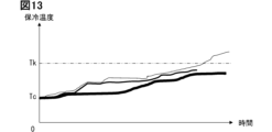
- posture planning routes for which the predicted cold storage temperature of the item Gc before reaching the destination is equal to or exceeds the allowable temperature Tk may be excluded from the optimal route candidates. Note that each line graph of different thickness in FIG. 13 individually indicates the correlation between time and cold storage temperature for each posture planning route.
- a future route (specifically, an optimal route) is determined in which the traveling posture is adjusted to the control posture Ac for each traveling point based on the power generation efficiency Eg of the power generation unit 9 and the cooling efficiency Ek of the goods Gc for each traveling point in each of the multiple planned future routes.
- This allows the posture of the light receiving surface 92 to be aligned with the predicted result of the sun direction Ds, and each of the efficiencies Eg, Ek used to adjust the position of the transport chamber 20 in the opposite direction Dr to the predicted result of the sun direction Ds can also be effectively used in route determination.
- the dedicated computer constituting the control system 1 may have at least one of a digital circuit and an analog circuit as a processor.
- the digital circuit is at least one of the following types: ASIC (Application Specific Integrated Circuit), FPGA (Field Programmable Gate Array), SOC (System on a Chip), PGA (Programmable Gate Array), and CPLD (Complex Programmable Logic Device).
- ASIC Application Specific Integrated Circuit
- FPGA Field Programmable Gate Array
- SOC System on a Chip
- PGA Programmable Gate Array
- CPLD Complex Programmable Logic Device
- the solar panel 90 may be fixed in position relative to the body 2.
- a control posture Ac that controls only one of the efficiencies Eg and Ek may be selected.
- a processing circuit e.g., a processing ECU, etc.
- a semiconductor device e.g., a semiconductor chip, etc.
- a control device that is configured to be mountable on the autonomous transport device Ma and has at least one processor 12 and one memory 10.
- a control system for controlling the autonomous travel of an autonomous transport device (Ma) that receives power from a power generation unit (9) that receives sunlight and generates power in order to store an item (Gc) that requires refrigeration in a transport chamber (20) and transport the item by autonomous travel comprising: The processor, Acquiring incident information (Is) regarding the incidence of the sunlight on the autonomous transport device; and adjusting the driving posture of the autonomous transport device during the autonomous driving to a control posture (Ac) that positions the transport chamber in a direction opposite to the sun direction (Ds) with respect to a light receiving surface (92) that is oriented in accordance with the incident information toward the sun direction (Ds) for receiving the sunlight in the power generation unit.
- the control system according to technical idea 1 includes controlling an attitude angle of the autonomous transport device on a travel path to orient the light receiving surface toward the sun.
- Adjusting the running posture includes:
- the control system according to technical idea 1 or 2 includes controlling the attitude angle of the power generation unit in the autonomous transport device to orient the light receiving surface toward the sun.
- Adjusting the running posture includes: A control system described in any one of technical ideas 1 to 3, which includes adjusting the running posture to the control posture that controls the cooling efficiency of the items that have been cooled before being loaded into the transport chamber.
- Adjusting the running posture includes: A control system described in any one of technical ideas 1 to 4, which includes adjusting the driving posture to the control posture that controls the cooling efficiency of the items that can be cooled during the autonomous driving in the transport chamber.
- Adjusting the running posture includes: A control system described in any one of technical ideas 1 to 5, which includes adjusting the driving posture to the control posture that maximizes energy efficiency that correlates with the power generation efficiency of the power generation unit and the cooling efficiency of the goods.
- the acquiring of the incident information includes: A control system described in any one of technical ideas 1 to 6, which includes predicting the sun direction at each traveling point on the future route of the autonomous transport device as the incidence information.
- Adjusting the running posture includes: A control system as described in technical idea 7, which includes adjusting the driving posture to the control posture that controls the power generation efficiency of the power generation unit and the cooling efficiency of the items at each driving point in accordance with the predicted result of the sun direction.
- Adjusting the running posture includes: A control system as described in technical idea 7 or 8, which includes determining the future route by adjusting the driving posture to the control posture for each driving point based on the power generation efficiency of the power generation unit and the cooling efficiency of the items at each driving point in each of the multiple planned future routes.
Landscapes
- Engineering & Computer Science (AREA)
- Power Engineering (AREA)
- Automation & Control Theory (AREA)
- Remote Sensing (AREA)
- Physics & Mathematics (AREA)
- General Physics & Mathematics (AREA)
- Radar, Positioning & Navigation (AREA)
- Aviation & Aerospace Engineering (AREA)
- Transportation (AREA)
- Mechanical Engineering (AREA)
- Control Of Position, Course, Altitude, Or Attitude Of Moving Bodies (AREA)
- Direct Current Feeding And Distribution (AREA)
- Electric Propulsion And Braking For Vehicles (AREA)
Abstract
保冷を要する物品を搬送室(20)に収容して自律走行により搬送するために、太陽光を受光して発電する発電ユニット(9)から電力の供給される自律搬送装置(Ma)の、自律走行を制御する制御システムが有するプロセッサは、自律搬送装置(Ma)への太陽光の入射に関する入射情報を取得することと、発電ユニットにおいて太陽光を受光するための太陽方向(Ds)へ入射情報に応じて向けられる受光面(92)に対して太陽方向(Ds)とは逆方向(Dr)に搬送室(20)を位置させる制御姿勢(Ac)に、自律走行における自律搬送装置(Ma)の走行姿勢を調整することとを、実行するように構成される。
Description
この出願は、2023年6月16日に日本に出願された特許出願第2023-99403号を基礎としており、基礎の出願の内容を、全体的に、参照により援用している。
本開示は、自律搬送装置の自律走行を制御する技術に、関する。
特許文献1の開示技術は、太陽光により発電する発電ユニットとして太陽電池を搭載した車両に対して、太陽光の照射量が多い将来ルートを探索している。
また一方、特許文献2の開示技術は、保冷を要する物品を搬送する自律搬送装置に対して、太陽光入射のシミュレーション結果に基づき、搬送環境の温度が低下する将来ルートを決定している。
しかし、保冷を要する物品を搬送する自律搬送装置として、太陽光による発電ユニットを搭載した装置に特許文献1の開示技術が利用される場合、将来ルートにおいて搬送環境の温度が上昇してしまう。逆に、保冷を要する物品を搬送する自律搬送装置として、太陽光による発電ユニットを搭載した装置に特許文献2の開示技術が利用される場合、将来ルートにおいて太陽光の照射量が減少してしまう。
こうした問題は、発電ユニットの発電効率と物品の保冷効率とが相反することに起因している。そこで、相反事象を省エネルギーの観点からブレークスルーする技術的解決が、期待されている。
本開示の課題は、省エネルギー化を図る制御システムを、提供することにある。本開示の別の課題は、省エネルギー化を図る制御装置を、提供することにある。本開示のまた別の課題は、省エネルギー化を図る制御方法を、提供することにある。本開示のさらに別の課題は、省エネルギー化を図る制御プログラムを、提供することにある。
以下、課題を解決するための本開示の技術的手段について、説明する。
本開示の第一態様は、
プロセッサを有し、保冷を要する物品を搬送室に収容して自律走行により搬送するために、太陽光を受光して発電する発電ユニットから電力の供給される自律搬送装置の、自律走行を制御する制御システムであって、
プロセッサは、
自律搬送装置への太陽光の入射に関する入射情報を取得することと、
発電ユニットにおいて太陽光を受光するための太陽方向へ入射情報に応じて向けられる受光面に対して太陽方向とは逆方向に搬送室を位置させる制御姿勢に、自律走行における自律搬送装置の走行姿勢を調整することとを、実行するように構成される。
プロセッサを有し、保冷を要する物品を搬送室に収容して自律走行により搬送するために、太陽光を受光して発電する発電ユニットから電力の供給される自律搬送装置の、自律走行を制御する制御システムであって、
プロセッサは、
自律搬送装置への太陽光の入射に関する入射情報を取得することと、
発電ユニットにおいて太陽光を受光するための太陽方向へ入射情報に応じて向けられる受光面に対して太陽方向とは逆方向に搬送室を位置させる制御姿勢に、自律走行における自律搬送装置の走行姿勢を調整することとを、実行するように構成される。
本開示の第二態様は、
プロセッサを有し、保冷を要する物品を搬送室に収容して自律走行により搬送するために、太陽光を受光して発電する発電ユニットから電力の供給される自律搬送装置に、搭載可能に構成されて自律搬送装置の自律走行を制御する制御装置であって、
プロセッサは、
自律搬送装置への太陽光の入射に関する入射情報を取得することと、
発電ユニットにおいて太陽光を受光するための太陽方向へ入射情報に応じて向けられる受光面に対して太陽方向とは逆方向に搬送室を位置させる制御姿勢に、自律走行における自律搬送装置の走行姿勢を調整することとを、実行するように構成される。
プロセッサを有し、保冷を要する物品を搬送室に収容して自律走行により搬送するために、太陽光を受光して発電する発電ユニットから電力の供給される自律搬送装置に、搭載可能に構成されて自律搬送装置の自律走行を制御する制御装置であって、
プロセッサは、
自律搬送装置への太陽光の入射に関する入射情報を取得することと、
発電ユニットにおいて太陽光を受光するための太陽方向へ入射情報に応じて向けられる受光面に対して太陽方向とは逆方向に搬送室を位置させる制御姿勢に、自律走行における自律搬送装置の走行姿勢を調整することとを、実行するように構成される。
本開示の第三態様は、
プロセッサにより実行される制御方法として、保冷を要する物品を搬送室に収容して自律走行により搬送するために、太陽光を受光して発電する発電ユニットから電力の供給される自律搬送装置の、自律走行を制御する制御方法であって、
自律搬送装置への太陽光の入射に関する入射情報を取得することと、
発電ユニットにおいて太陽光を受光するための太陽方向へ入射情報に応じて向けられる受光面に対して太陽方向とは逆方向に搬送室を位置させる制御姿勢に、自律走行における自律搬送装置の走行姿勢を調整することとを、含む。
プロセッサにより実行される制御方法として、保冷を要する物品を搬送室に収容して自律走行により搬送するために、太陽光を受光して発電する発電ユニットから電力の供給される自律搬送装置の、自律走行を制御する制御方法であって、
自律搬送装置への太陽光の入射に関する入射情報を取得することと、
発電ユニットにおいて太陽光を受光するための太陽方向へ入射情報に応じて向けられる受光面に対して太陽方向とは逆方向に搬送室を位置させる制御姿勢に、自律走行における自律搬送装置の走行姿勢を調整することとを、含む。
本開示の第四態様は、
記憶媒体に記憶される制御プログラムとして、保冷を要する物品を搬送室に収容して自律走行により搬送するために、太陽光を受光して発電する発電ユニットから電力の供給される自律搬送装置の、自律走行を制御するプロセッサに実行させるための命令を含む制御プログラムであって、
自律搬送装置への太陽光の入射に関する入射情報を取得することと、
発電ユニットにおいて太陽光を受光するための太陽方向へ入射情報に応じて向けられる受光面に対して太陽方向とは逆方向に搬送室を位置させる制御姿勢に、自律走行における自律搬送装置の走行姿勢を調整することとを、実行させるための命令を含む。
記憶媒体に記憶される制御プログラムとして、保冷を要する物品を搬送室に収容して自律走行により搬送するために、太陽光を受光して発電する発電ユニットから電力の供給される自律搬送装置の、自律走行を制御するプロセッサに実行させるための命令を含む制御プログラムであって、
自律搬送装置への太陽光の入射に関する入射情報を取得することと、
発電ユニットにおいて太陽光を受光するための太陽方向へ入射情報に応じて向けられる受光面に対して太陽方向とは逆方向に搬送室を位置させる制御姿勢に、自律走行における自律搬送装置の走行姿勢を調整することとを、実行させるための命令を含む。
これら第一~第四態様によると、保冷を要する物品を搬送室に収容して自律走行により搬送するために、太陽光を受光して発電する発電ユニットから電力の供給される自律搬送装置の、自律走行が制御される。そこで第一~第四態様では、自律搬送装置への太陽光の入射に関する入射情報が取得されることで、自律走行における自律搬送装置の走行姿勢が当該入射情報に応じて調整される。このとき具体的には、発電ユニットにおいて太陽光を受光するための太陽方向へ入射情報に応じて向けられる受光面に対して、当該太陽方向とは逆方向に搬送室を位置させる制御姿勢へと、走行姿勢が調整されることになる。これによれば、受光面が太陽方向に向く発電ユニットでは発電効率を確保しつつ、受光面に対して太陽方向とは逆方向の搬送室では物品の保冷効率を確保して、省エネルギー化を図ることが可能である。
以下、本開示の実施形態を図面に基づき複数説明する。尚、各実施形態において対応する構成要素には同一の符号を付すことで、重複する説明を省略する場合がある。また、各実施形態において構成の一部分のみを説明している場合、当該構成の他の部分については、先行して説明した他の実施形態の構成を適用することができる。さらに、各実施形態の説明において明示している構成の組み合わせばかりではなく、特に組み合わせに支障が生じなければ、明示していなくても複数の実施形態の構成同士を部分的に組み合わせることができる。
図1に示す第一実施形態の制御システム1は、図2,3に示すように物品Gcを搬送室20に収容して自律走行により搬送する自律搬送装置Maの、当該自律走行を制御する。自律搬送装置Maは、水平面に沿う任意方向へ自律走行可能に構築されている。
自律搬送装置Maは、保冷を要する物品Gcを搬送対象としている。保冷を要する物品Gcは、例えば冷蔵品、冷凍品、及び常温保存品等うち、少なくとも一種類の食品類であってもよい。保冷を要する物品Gcは、食品類以外の例えば医薬品、飼料、溶剤、溶液、雑品、建材、及び電子機器等のうち、少なくとも一種類であってもよい。こうした保冷を要する物品Gcは、例えばダンボール箱、発泡スチロールケース、プラスチックケース、及びプラスチックフィルム等のうち、少なくとも一種類により梱包又は包装された状態で搬送室20に積載されてもよい。尚、自律搬送装置Maは、保冷を要する物品Gcを搬送可能に構築されている限りにて、保冷の不要な物品Gcを搬送してもよい。
自律搬送装置Maは、走行エリアとしての外界ルート上の走行路(即ち、道路)、若しくは走行エリアとしてのスマートシティにおける建造物内外の走行路を自律走行して物品Gcとしての荷物を配送する、配送車両又は配送ロボットであってもよい。自律搬送装置Maは、走行エリアとしての物流施設において倉庫内外の走行路を自律走行して物品Gcとしての荷物を運搬する、運搬車両又は運搬ロボットであってもよい。自律搬送装置Maは、走行エリアとしての飲食店内若しくは病院内の走行路を自律走行して物品Gcとしての飲食物を配膳する、配膳ロボットであってもよい。自律搬送装置Maは、走行エリアとしての災害地に走行可能な走行路を探索しつつ自律走行して物品Gcとしての物資を運搬する、災害支援ロボットであってもよい。自律搬送装置Maは、これら以外の装置であっても勿論よい。さらにいずれの種の自律搬送装置Maも、外部センタによりリモートでの走行支援又は走行制御を受けてもよい。
自律搬送装置Maは、ボディ2、駆動系3、バッテリ4、センサ系5、通信系6、地図データベース7、及び情報提示系8を備えている。ボディ2は、例えば金属等により中空状に形成されている。ボディ2は、自律搬送装置Maの他の構成要素を、内部に又は内部から外部に跨って保持している。
ボディ2は、搬送対象として自律搬送装置Maに外部から積載される物品Gcを内部に収容するために、搬送室20を形成している。搬送室20は、例えば保冷コンテナの内部空間等として断熱材製の室壁により箱状に取り囲まれていることで、物品Gcに対する保冷性能を発揮可能に構成されているとよい。搬送室20は、ボディ2に搭載された冷却ユニット21(図3の二点鎖線参照)による冷却機能により、物品Gcを設定温度以下に保冷可能に構成されていてもよい。ここで冷却ユニット21は、搬送室20の空調温度を調整する空調ユニットであってもよいし、搬送室20内の物品Gcを冷蔵(又は冷凍)する冷蔵ユニットであってもよい。
駆動系3は、車輪30、及び電動アクチュエータ34を備えている。車輪30は、ボディ2により複数支持されている。各車輪30は、それぞれ独立して回転可能に構成されている。複数車輪30のうち、ボディ2の左右に一つずつとなる一対の駆動輪300は、それぞれ個別の電動アクチュエータ34により独立して駆動される。特に本実施形態では、これら各駆動輪300間での回転速度差(即ち、単位時間当たりの回転数差)に応じて、自律搬送装置Maの走行状態が直進走行と旋回走行とのいずれかに切り替わる。
具体的には、左右二つの駆動輪300間での回転速度差が零値、又は零値と擬制可能な範囲では、自律搬送装置Maが直進駆動される。一方、左右の駆動輪300間での回転速度差が増大する範囲では、自律搬送装置Maの旋回駆動される旋回半径が、当該回転速度差の増大に応じて縮小する。ここで旋回半径とは、ボディ2の鉛直中心線と旋回駆動の旋回中心との平面視における距離を意味することから、旋回半径が実質0に縮小される旋回駆動は、点旋回駆動となる。尚、複数の車輪30には、駆動輪300に従動して回転する少なくとも一つの従動輪が、含まれていてもよい。
図3に示すバッテリ4は、ボディ2に少なくとも一つ、搭載される。バッテリ4は、例えばリチウムイオン電池等の蓄電池を主体に、構成されている。バッテリ4は、放電によりボディ2内の電装品へと供給する電力として、発電ユニット9からの出力電力を蓄積する。バッテリ4は、放電によりボディ2内の電装品へと供給する電力を、外部からの充電により蓄積してもよい。バッテリ4は、電動アクチュエータ34からの回生電力を、蓄積してもよい。バッテリ4は、電力の供給先となる電動アクチュエータ34、センサ系5、通信系6、地図データベース7、情報提示系8、及び発電ユニット9に対し、ワイヤハーネスを介して電力供給可能に接続されている。バッテリ4は、ボディ2に搭載される場合の冷却ユニット21にも、ワイヤハーネスを介して電力供給可能に接続されていてもよい。
電動アクチュエータ34は、ボディ2により一対支持されている。ボディ2の左右に一つずつとなる各電動アクチュエータ34は、それぞれ電動モータ340及びモータドライバ341の組を主体に構成されている。各電動アクチュエータ34において電動モータ340は、それぞれ対応する駆動輪300を独立して回転駆動する。各電動アクチュエータ34においてモータドライバ341は、同一組の電動モータ340へ印加する電流を制御システム1からの電流指令値に応じて調整することで、それぞれ対応する駆動輪300に対して当該電流指令値に従う駆動トルクの出力を制御する。各電動アクチュエータ34は、それぞれ対応する駆動輪300の回転中に制動を与える、ブレーキユニットを備えているとよい。
図2,3に示すセンサ系5は、制御システム1により利用可能なセンシング情報を、自律搬送装置Maにおける外界及び内界のセンシングにより取得する。そのためにセンサ系5の構成要素は、ボディ2の複数箇所に搭載されている。具体的にセンサ系5は、外界センサ50と内界センサ51とを含んで構成されている。
外界センサ50は、自律搬送装置Maの周囲環境となる外界から、センシング情報としての外界情報を取得する。外界センサ50は、自律搬送装置Maの外界に存在する物体を検知することで、外界情報を取得する。物体検知タイプの外界センサ50は、例えばカメラ、LiDAR(Light Detection and Ranging / Laser Imaging Detection and Ranging)、レーダ、ソナー、周囲光センサ、及び衝撃センサ等のうち、少なくとも一種類である。
図3に示す内界センサ51は、自律搬送装置Maの内部環境となる内界から、センシング情報としての内界情報を取得する。内界センサ51は、自律搬送装置Maの内界において特定の運動物理量を検知することで、内界情報を取得する物理量検知タイプであってもよい。物理量検知タイプの内界センサ51は、例えば速度センサ、加速度センサ、及び慣性センサ等のうち、少なくとも一種類である。内界センサ51は、自律搬送装置Maの内界となる搬送室20内を検知することで、内界情報を取得する室内検知タイプであってもよい。室内検知タイプの内界センサ51は、例えば温度センサ、重量センサ、圧力センサ、カメラ、及びRFID(Radio Frequency Identifier)リーダ等のうち、少なくとも一種類である。
通信系6は、制御システム1により利用可能な通信情報を、自律搬送装置Maの外界との間における無線通信により送受信する。通信系6は、自律搬送装置Maの外界に存在するGNSS(Global Navigation Satellite System)の人工衛星から測位信号を受信することで、通信情報を取得する測位タイプであってもよい。測位タイプの通信系6は、例えばGNSS受信機等である。
通信系6は、自律搬送装置Maの外界に存在するV2Xシステムとの間において通信情報を送受信する、V2Xタイプであってもよい。V2Xタイプの通信系6は、例えばDSRC(Dedicated Short Range Communications)通信機、及びセルラV2X(C-V2X)通信機等のうち、少なくとも一種類である。通信系6は、自律搬送装置Maの外界に存在する移動端末との間において通信情報を送受信する端末通信タイプであってもよい。端末通信タイプの通信系6は、例えばブルートゥース(Bluetooth:登録商標)機器、Wi-Fi(登録商標)機器、及び赤外線通信機器等のうち、少なくとも一種類である。
地図データベース7は、制御システム1により利用可能な地図情報を、記憶する。地図データベース7は、例えば半導体メモリ、磁気媒体、及び光学媒体等のうち、少なくとも一種類の非遷移的実体的記憶媒体(non-transitory tangible storage medium)を含んで構成されている。地図データベース7は、自律搬送装置Maの自己位置を推定するロケータの、データベースであってもよい。地図データベース7は、自律搬送装置Maの走行を計画するプランニングユニットの、データベースであってもよい。地図データベース7は、これらのデータベース等のうち複数種類の組み合わせにより、構成されていてもよい。
地図データベース7は、例えば外部センタとの通信等により、最新の地図情報を取得して記憶する。ここで地図情報は、自律搬送装置Maの走行エリアを表す情報として、二次元又は三次元にデータ化されている。特に三次元の地図データとしては、高精度地図のデジタルデータが採用されるとよい。ここで地図情報は、例えば外部センタ等のインフラシステムにおけるインフラデータベースから通信系6を介して地図データベース7にダウンロードされたデータとして、取得されてもよい。このとき特に地図情報は、走行エリアを三次元配列状に仮想分割した複数の三次元ボクセル(即ち、三次元グリッド)別に、又は走行エリアを二次元タイル状に仮想分割した複数の二次元グリッド別に、それぞれ個別の空間IDと紐付られて取得されてもよい。
地図データベース7に記憶される地図情報は、例えば走行路に関する位置座標、サイズ、形状、及び路面状態等のうち、少なくとも一種類を表した走行路情報を含んでいてもよい。地図情報は、例えば走行路に面した建造物、構造物、及び植栽物に関する位置座標、サイズ、並びに形状等のうち、少なくとも一種類を表した静止物情報を含んでいてもよい。地図情報は、例えば走行路としての道路に付属する標識、区画線、及び信号機に関する位置座標、サイズ、並びに形状等のうち、少なくとも一種類を表した道路標示情報を含んでいてもよい。
情報提示系8は、自律搬送装置Maの周囲者へ向けた報知情報を、提示する。情報提示系8は、周囲者の視覚を刺激することで、報知情報を提示してもよい。視覚刺激タイプの情報提示系8は、例えばモニタユニット、及び発光ユニット等のうち、少なくとも一種類である。情報提示系8は、周囲者の聴覚を刺激することで、報知情報を提示してもよい。聴覚刺激タイプの情報提示系8は、例えばスピーカ、ブザー、及びバイブレーションユニット等のうち、少なくとも一種類である。
図2,3に示すように発電ユニット9は、ソーラーパネル90を備えている。ソーラーパネル90は、受光した太陽光のエネルギーを電力へと変換して出力可能な、例えばシリコン系、化合物系、有機物系、又は量子ドット系等のパネルである。ソーラーパネル90は、太陽光を受光するための受光面92を、形成している。ソーラーパネル90は、受光面92における太陽光の受光に応じた発電により一旦バッテリ4へと蓄積される電力を、出力する。その結果、ソーラーパネル90からの出力電力は、保冷を要する物品Gcを搬送室20内に収容して自律走行により搬送するために、少なくとも利用される。
ソーラーパネル90は、特に本実施形態では、ボディ2に対して相対駆動自在に支持されている。これにより、自律搬送装置Maにおけるソーラーパネル90の姿勢角として、水平面内の方位角と鉛直面内の仰角とのうち少なくとも仰角が、発電ユニット9に搭載された姿勢調整ユニット91により調整可能となっている。
図1に示す制御システム1は、自律搬送装置Maの外界及び自己位置を認識しつつ、計画した将来ルートにおける同装置Maの自律走行を制御する。そのために制御システム1は、ボディ2に搭載されたコンピュータを含んだ、少なくとも一つの専用コンピュータから構成されている。そこで、制御システム1を構成する専用コンピュータは、例えばLAN(Local Area Network)回線、ワイヤハーネス、内部バス、及び無線通信回線等のうち少なくとも一種類を介して、電動アクチュエータ34、バッテリ4、センサ系5、通信系6、地図データベース7、情報提示系8、及び発電ユニット9に接続されている。制御システム1を構成する専用コンピュータは、ボディ2に搭載される場合の冷却ユニット21には、例えばLAN回線、ワイヤハーネス、及び内部バス等のうち少なくとも一種類を介して接続されていてもよい。
制御システム1を構成する専用コンピュータは、自律搬送装置Maの走行計画として将来ルートを計画する、プランニングECU(Electronic Control Unit)であってもよい。制御システム1を構成する専用コンピュータは、自律搬送装置Maの電動アクチュエータ34を制御する、アクチュエータECUであってもよい。制御システム1を構成する専用コンピュータは、自律搬送装置Maのバッテリ4を制御する、電源ECUであってもよい。制御システム1を構成する専用コンピュータは、自律搬送装置Maのセンサ系5を制御する、センシングECUであってもよい。
制御システム1を構成する専用コンピュータは、自律搬送装置Maの自己位置を地図データベース7に基づき推定する、ロケータECUであってもよい。制御システム1を構成する専用コンピュータは、自律搬送装置Maの情報提示系8を制御する、情報提示ECUであってもよい。制御システム1を構成する専用コンピュータは、自律搬送装置Maの発電ユニット9を制御する、発電ECUであってもよい。制御システム1を構成する専用コンピュータは、例えば通信系6を介して通信可能な外部センタ又はモバイル端末等を構成する、ボディ2外のコンピュータであってもよい。
制御システム1を構成する専用コンピュータは、メモリ10及びプロセッサ12を、少なくとも一つずつ有している。メモリ10は、コンピュータにより読み取り可能なプログラム及びデータ等を非一時的に記憶する、例えば半導体メモリ、磁気媒体、及び光学媒体等のうち、少なくとも一種類の非遷移的実体的記憶媒体(non-transitory tangible storage medium)である。プロセッサ12は、例えばCPU(Central Processing Unit)、GPU(Graphics Processing Unit)、RISC(Reduced Instruction Set Computer)-CPU、DFP(Data Flow Processor)、及びGSP(Graph Streaming Processor)等のうち、少なくとも一種類をコアとして含んでいる。
制御システム1においてプロセッサ12は、自律搬送装置Maの自律走行を制御するためにメモリ10に記憶された、制御プログラムに含まれる複数の命令を実行する。これにより制御システム1は、自律搬送装置Maの自律走行を制御するための機能ブロックを、複数構築する。制御システム1において構築される複数の機能ブロックには、図4に示すように監視ブロック100、及び制御ブロック110が含まれている。
これらのブロック100,110の共同により、制御システム1が自律搬送装置Maの自律走行を制御するための制御方法は、図5に示す制御フローに従って実行される。第一実施形態の制御フローは、自律搬送装置Maの起動後において自律走行による物品Gcの搬送が開始されると、同装置Maが将来ルートの目的地に到着するまで、繰り返し実行される。尚、制御フローにおける各「S」は、制御プログラムに含まれた複数命令によって実行される各ステップを、それぞれ意味している。
S10において監視ブロック100は、自律搬送装置Maへの太陽光の入射に関する入射情報Isを取得する。このとき入射情報Isは、自律搬送装置Maから視て太陽の存在する三次元方向として、太陽方向Ds(図6,7参照)を含む。ここで太陽方向Dsとは、自律搬送装置Maに計画された将来ルートにおける走行ポイントのうち、最新の制御対象となる制御走行ポイントにおいて、水平面内の方位角と鉛直面内の仰角との、双方により定義される。
S10において取得される入射情報Isには、太陽方向Dsに加えて、例えば太陽の高度又は位置、太陽光の照度又は入射量、天候情報、及び将来ルート上の日陰情報等のうち、少なくとも一種類を太陽方向Dsに加えて含んでいてもよい。以上より太陽方向Dsを少なくとも含む入射情報Isは、例えば外界センサ50としての周囲光センサのセンシング情報、通信系6の通信情報である気象情報、通信系6の通信情報である測位情報、地図データベース7の地図情報、及びロケータECUの自己位置情報等のうち、少なくとも一つとなる必要種類に基づいて取得されるとよい。但し、後述するS20において否定判定が下されるような環境状態の制御走行ポイントに関しては、入射情報Isとしての太陽方向Dsの取得がスキップされてもよい。
制御フローでは、S10の実行完了に後続してS20が実行される。S20において監視ブロック100は、自律搬送装置Maの外界における環境状態が、同装置Maに対して太陽光の入射する日照状態にあるか否かを、判定する。このとき日照状態の判定は、S10により取得の入射情報Isに基づく。
制御フローにおいてS20により肯定判定が下されると、S30が実行される。S30において制御ブロック110は、自律走行における自律搬送装置Maの走行姿勢を計画する。このとき自律搬送装置Maの走行姿勢は、自律搬送装置Maに計画された将来ルートにおける走行ポイントのうち、最新の制御対象となる制御走行ポイントに関して、最適化された制御姿勢Acに計画される。
S30において制御姿勢Acは、図6,7に示すように、発電ユニット9のソーラーパネル90において太陽光を受光するために太陽方向Dsに向けられる受光面92に対して、太陽方向Dsとは逆方向Drに搬送室20を位置させる走行姿勢に、定義される。そこで、最新の制御走行ポイントでの調整を計画される制御姿勢Acでは、S20により取得の入射情報Isに応じて太陽方向Dsに受光面92が向けられるソーラーパネル90によって逆方向Drに生じる影内に、搬送室20の少なくとも一部が位置するとよい。
S30における走行姿勢の計画では、自律搬送装置Maの走行路における姿勢角を水平面内にて各電動アクチュエータ34により制御することで、受光面92を太陽方向Dsに向けると同時に逆方向Drに搬送室20を位置させる制御姿勢Acへの調整が、想定されてもよい。走行姿勢の計画では、自律搬送装置Maにおけるソーラーパネル90の姿勢角を水平面内及び鉛直面内のうち少なくとも鉛直面内にて姿勢調整ユニット91により制御することで、受光面92を太陽方向Dsに向けると同時に逆方向Drに搬送室20を位置させる制御姿勢Acへの調整が、想定されてもよい。走行姿勢の計画では、走行路における自律搬送装置Maの姿勢角調整と、自律搬送装置Maにおけるソーラーパネル90の姿勢角調整との、双方が想定されてもよい。
S30の計画段階において走行姿勢の制御目標ともいえる制御姿勢Acは、発電ユニット9におけるソーラーパネル90の発電効率Egと、搬送室20内における物品Gcの保冷効率Ekとを制御するように、それら効率Eg,Ekの相関に基づき設定される。そこで制御姿勢Acは、各効率Eg,Ek毎の重みωg,ωkを用いた次の数1に従って、それら効率Eg,Ekに相関するエネルギー効率Eeを、最大化する制御目標として設定される。このためにS30では、図6に示すように太陽方向Dsに対して受光面92が直交する基準姿勢Abと、図7に示すように太陽方向Dsに対して受光面92が傾斜する傾斜姿勢Asの少なくとも一つとが、制御姿勢Acの候補として想定される。

S30において発電効率Egは、各姿勢Ab,Asでのソーラーパネル90の発電電力に関して、基準姿勢Abでの発電電力を基準とした相対比により、発電性能指標として取得される。このとき各姿勢Ab,Asでの発電効率Egの取得は、例えば太陽方向Ds、太陽の高度又は位置、太陽光の照度又は入射量、将来ルート上の日陰情報、ソーラーパネル90の温度、及び発電ユニット9としての発電性能等のうち、少なくとも太陽方向Dsを含む発電関連パラメータに基づく。そこで、発電効率Egの取得に際して発電関連パラメータは、例えばS10により取得の入射情報Is、及び発電ユニット9における状態検知情報等のうち、少なくとも一つとなる必要種類に基づいて把握されるとよい。
S30において保冷効率Ekは、各姿勢Ab,Asでの物品Gcの単位温度上昇あたりの上昇時間に規定される温度上昇時間に関して、基準姿勢Abでの温度上昇時間を基準とした相対比により、保冷性能指標として取得される。このときには、搬送室20への積載前において冷却された物品Gcの保冷温度に関して、図8,9に示すように当該積載前の冷却温度Tcに応じた各姿勢Ab,Asでの温度上昇時間が予測されることで、保冷効率Ekが取得されてもよい。保冷効率Ekは、冷却ユニット21が搭載される場合の搬送室20において自律走行中に冷却可能な物品Gcの保冷温度に関して、図9に示すように当該ユニット21の冷却性能に応じた各姿勢Ab,Asでの温度上昇時間が予測されることで、取得されてもよい。尚、図8,9は、温度上昇時間に関する説明の理解を容易にするため、物品Gcの積載直後を起点とした時間及び保冷温度の相関を模式的に示しているが、実際には、過去回の制御フローによる制御姿勢Acに応じた保冷温度の時間変化が、温度上昇時間の予測に考慮されるとよい(後述する第三実施形態の図12参考)。
S30において各姿勢Ab,Asでの保冷効率Ekの取得は、例えば太陽方向Ds又は逆方向Dr、ソーラーパネル90による影の生成情報、外界の環境温度、積載時における物品Gcの初期温度、積載時における搬送室20内の初期温度、搬送室20での冷却性能、及び将来ルート上の日陰情報等のうち、少なくとも方位Ds又はDrを含む保冷関連パラメータに基づく。そこで、保冷効率Ekの取得に際して保冷関連パラメータは、例えばS10により取得の入射情報Is、内界センサ51としての温度センサの温度情報、及び積載前における物品Gcの冷却条件情報等のうち、少なくとも一つとなる必要種類に基づいて把握されるとよい。
S30において各効率Eg,Ekに基づくエネルギー効率Eeは、制御姿勢Acの候補となる姿勢Ab,As別に取得される。このとき、先述の如くエネルギー効率Eeを与える数1において各効率Eg,Ek毎の重みωg,ωkは、例えばシミュレーションモデル、関数、マップ、又はテーブル等を用いた、ルールベースで設定される。
具体的にS30では、例えばバッテリ4における蓄積電力の閾値以下又は未満への下降等といった条件の成立により、発電効率Egの重みωgが保冷効率Ekの重みωkよりも大きい関係に、また当該条件の不成立により逆の関係に調整されてもよい。S30では、例えば外界の低い環境温度(即ち、外気温)に応じて搬送室20内の温度に関する時間変化率の閾値以下又は未満への下降等といった条件の成立により、発電効率Egの重みωgが保冷効率Ekの重みωkよりも大きい関係に、また当該条件の不成立により逆の関係に調整されてもよい。
S30では、例えば搬送室20内における温度の閾値以上又は超過への上昇等といった条件の成立により、発電効率Egの重みωgよりも保冷効率Ekの重みωkが大きい関係に、また当該条件の不成立により逆の関係に調整されてもよい。S30では、例えば積載前に冷却された物品Gcに関する閾値以上又は超過の冷却温度等といった条件の成立により、発電効率Egの重みωgよりも保冷効率Ekの重みωkが大きい関係に、また当該条件の不成立により逆の関係に調整されてもよい。
以上より、S30において制御姿勢Acには、その候補となる姿勢Ab,Asの中から、エネルギー効率Eeを最大化する最適姿勢が、選定される。但し、S30では、例えば過去回の制御フローにおいて実行されたS30により選定の制御姿勢Acからの連続性、及び走行ポイント別での走行環境に応じた姿勢制限等のうち、少なくとも一種類に基づくことで、エネルギー効率Eeが最大効率未満の中で可及的に大きな姿勢Ab又はAsであれば、最適な制御姿勢Acと擬制して選定されてもよい。尚、各効率Eg,Ek毎の重みωg,ωkは、機械学習モデルによりエネルギー効率Eeを最大化するように、それぞれ調整されることで、当該最大化されたエネルギー効率Eeに対応する制御姿勢Acが選定されてもよい。
図5に示すように制御フローでは、S30の実行完了に後続してS40が実行される。S40において制御ブロック110は、S30により選定された制御姿勢Acに従って、最新の制御走行ポイントにおける自律搬送装置Maの走行姿勢を調整する。このとき、例えばソーラーパネル90の温度上昇により、S30により選定された制御姿勢Acに対応する発電効率Ekの大幅な低下が懸念される場合等には、自律搬送装置Maの走行速度が高められることで、ソーラーパネル90の走行風による空冷が図られてもよい。制御フローの今回実行は、S40の実行完了に応じて終了する。
一方で制御フローでは、S20において否定判定が下されると、S50が実行される。S50において制御ブロック110は、最新の制御走行ポイントにおける自律搬送装置Maの走行姿勢を調整する。但し、S50において走行姿勢は、同装置Maの起動後における過去回の制御フローにおいて実行されたS30により選定の制御姿勢Acのうち最新姿勢、又は過去回の制御フローにおいてS30が一度も実行されていない場合のデフォルト姿勢に、制御される。制御フローの今回実行は、S50の実行完了に応じても終了する。
(作用効果)
ここまで説明した第一実施形態の作用効果を、以下に説明する。
ここまで説明した第一実施形態の作用効果を、以下に説明する。
第一実施形態によると、保冷を要する物品Gcを搬送室20に収容して自律走行により搬送するために、太陽光を受光して発電する発電ユニット9から電力の供給される自律搬送装置Maの、自律走行が制御される。そこで第一実施形態では、自律搬送装置Maへの太陽光の入射に関する入射情報Isが取得されることで、自律走行における自律搬送装置Maの走行姿勢が当該入射情報Isに応じて調整される。このとき具体的には、発電ユニット9において太陽光を受光するための太陽方向Dsに入射情報Isに応じて向けられる受光面92に対して、当該太陽方向Dsとは逆方向Drに搬送室20を位置させる制御姿勢Acへと、走行姿勢が調整されることになる。これによれば、受光面92が太陽方向Dsに向く発電ユニット9では発電効率Egを確保しつつ、受光面92に対して太陽方向Dsとは逆方向Drの搬送室20では物品Gcの保冷効率Ekを確保して、省エネルギー化を図ることが可能である。
第一実施形態によると、走行路における自律搬送装置Maの姿勢角が制御されることで、発電ユニット9の受光面92が太陽光の太陽方向Dsに向けられてもよい。これによれば、発電効率Egを確保するために受光面92を太陽方向Dsに姿勢合わせすることも、保冷効率Ekを確保するために受光面92に対して太陽方向Dsとは逆方向Drに搬送室20を位置調整することも、自律搬送装置Ma全体での姿勢角制御により正確に実現することができる。故に、省エネルギー化の信頼性を高めることが可能となる。
第一実施形態によると、自律搬送装置Maにおける発電ユニット9の姿勢角が制御されることで、発電ユニット9の受光面92が太陽光の太陽方向Dsに向けられてもよい。これによれば、発電効率Egを確保するために受光面92を太陽方向Dsに姿勢合わせすることも、保冷効率Ekを確保するために受光面92に対して太陽方向Dsとは逆方向Drに搬送室20を位置調整することも、発電ユニット9に対する個別の姿勢角制御により正確に実現することができる。故に、省エネルギー化の信頼性を高めることが可能となる。
第一実施形態によると、搬送室20への積載前において冷却された物品Gcの保冷効率Ekを制御する制御姿勢Acに、自律搬送装置Maの走行姿勢が調整されてもよい。これによれば、受光面92に対して太陽方向Dsとは逆方向Drの搬送室20における保冷効率Ekを、冷却状態の物品Gcにとっての最適効率に制御して、省エネルギー化を図ることが可能となる。さらには、積載前における物品Gcの冷却温度及び/又は冷却時間を可及的に低減しつつ、当該低減に応じた保冷効率Ekの最適制御することで、省エネルギー化を促進することも可能となる。
第一実施形態によると、搬送室20において自律走行中に冷却可能な物品Gcの保冷効率Ekを制御する制御姿勢Acに、自律搬送装置Maの走行姿勢が調整されてもよい。これによれば、特に受光面92に対して太陽方向Dsとは逆方向Drの搬送室20での保冷効率Ekを、冷却機能(具体的には冷却ユニット21)の活用により最適効率に制御して、省エネルギー化を図ることが可能となる。
第一実施形態によると、発電ユニット9の発電効率Egと物品Gcの保冷効率Ekとに相関するエネルギー効率Eeを最大化する制御姿勢Acに、自律搬送装置Maの走行姿勢が調整される。これによれば、受光面92が太陽方向Dsに向く発電ユニット9での発電効率Egと、受光面92に対して太陽方向Dsとは逆方向Drに位置する搬送室20での保冷効率Ekとを、エネルギー効率Eeを最大化する観点からの制御姿勢Acの調整により最適化することができる。故に、自律搬送装置Maの走行環境に応じた省エネルギー化を図ることが可能となる。
(第二実施形態)
第二実施形態は、第一実施形態の変形例である。図10に示す第二実施形態の制御フローは、自律搬送装置Maの起動後に、一回実行される。
第二実施形態は、第一実施形態の変形例である。図10に示す第二実施形態の制御フローは、自律搬送装置Maの起動後に、一回実行される。
S200において監視ブロック100は、自律搬送装置Maの将来ルートにおいて設定距離間隔毎又は設定時間間隔毎に計画される複数の走行ポイントの中から、制御姿勢Acを予め計画する計画走行ポイントを、選択する。ここで計画走行ポイントは、S200の各回実行毎に、将来ルートの目的地に対して遠い順又は近い順に一走行ポイントずつ、選択されるとよい。
制御フローでは、S200の実行完了に後続してS210が実行される。S210において監視ブロック100は、S200により選択された最新の計画走行ポイントに関する入射情報Isとして、発電ユニット9のソーラーパネル90における太陽光の太陽方向Dsを予測する。このとき、第一実施形態のS20と同様に定義される太陽方向Dsは、例えば通信系6の通信情報である気象情報、通信系6の通信情報である測位情報、地図データベース7の地図情報、及びロケータECUの自己位置情報等のうち、少なくとも一つとなる必要種類に基づいて予測されるとよい。但し、後述するS220において否定予測が与えられるような環境状態の計画走行ポイントに関しては、太陽方向Dsの予測がスキップされてもよい。
制御フローでは、S210の実行完了に後続してS220が実行される。S220において監視ブロック100は、自律搬送装置Maの外界における環境状態が、同装置Maに対して太陽光の入射する日照状態となるか否かを、S200により選択された計画走行ポイントに関して予測する。このとき日照状態の予測は、S210により取得の入射情報Isに基づく。
制御フローにおいてS220により肯定予測が与えられる場合には、S230が実行される。S230において制御ブロック110は、S200により選択された最新の計画走行ポイントに関しての、自律走行における自律搬送装置Maの走行姿勢として、第一実施形態のS30に準じた制御姿勢Acを計画する。但し、S230では、S210による太陽方向Dsの予測結果に応じて、発電ユニット9の発電効率Egと物品Gcの保冷効率Ekとを制御する制御姿勢Acへと調整されるように、自律搬送装置Maの走行姿勢が最新の計画ポイントに対して計画される。
制御フローでは、S230の実行完了に後続してS231が実行される。S231において監視ブロック100は、自律搬送装置Maに計画された将来ルートにおける全ての走行ポイントが計画走行ポイントに予設定されることで、制御姿勢Acの計画が完了状態にあるか否かを、判定する。その結果、否定判定が下された場合には、制御フローがS200に戻ることで、制御姿勢Acの計画が未完了な走行ポイントの中から、次の計画走行ポイントが選択される。
また制御フローでは、S220において否定予測が与えられると、S232の実行後にS231が同様に実行される。ここで、S232において制御ブロック110は、S200により選択された計画走行ポイントに関して、自律走行における自律搬送装置Maの走行姿勢を、S230とは異なる定義の制御姿勢Acに計画する。具体的にS232における制御姿勢Acは、今回の制御フローにおいて既に実行されたS230により選定の制御姿勢Acのうち、今回と最も近い位置の計画走行ポイントに関する選定姿勢、又は今回の制御フローにおいてS230が一度も実行されていない場合のデフォルト姿勢に、定義される。こうしてS232が経由される場合でも、S231にて否定判定が下された場合には、制御フローがS200に戻る。
S232の経由の有無に拘わらず、即ちS220の予測結果に拘わらず、S231において肯定判定が下された場合には、S240が実行される。S240において監視ブロック100は、自律搬送装置Maの自律走行による物品Gcの搬送が開始されたか否かを、判定する。その結果、否定判定が下される間は、S240の実行が繰り返される。
一方、S240において肯定判定が下されると、S241が実行される。S241において制御ブロック110は、S230又はS232により制御姿勢Acの計画された計画走行ポイントのいずれかに、自律走行による最新の制御走行ポイントが到達したか否かを、判定する。その結果、否定判定が下される間は、直近に調整された制御姿勢Acでの自律走行制御が維持されたまま、S241の実行が繰り返される。
制御フローでは、S241において肯定判定が下されると、S242が実行される。S242において制御ブロック110は、到達した最新の制御走行ポイントに対応する計画走行ポイントでの制御姿勢Acに従うように、第一実施形態のS40に準じて自律搬送装置Maの走行姿勢を調整する。
ここで、走行ポイント別のエネルギー効率Eeに関して、S230での最適値と観測値とでの偏差が許容範囲外に上昇する場合には、S242と並行してS200~S241が再実行されて、走行ポイント別の制御姿勢Acが再計画されてもよい。またこの場合、S230におけるエネルギー効率Eeの最適化に機械学習モデルが第一実施形態のS30に準じて活用される場合、当該最適値と観測値とに基づき機械学習モデルが更新されてもよい。以上の他、S230での各効率Eg,Ekの予測値及びそれに基づくエネルギー効率Eeの最適値が、例えば外部センタ等において制御システム1の少なくとも一部を構成する専用コンピュータにより、複数の自律搬送装置Maに関して取得されて対比されることで、将来ルートに最適な自律搬送装置Maが選定されてもよい。
S242の実行完了に後続するS243において制御ブロック110は、自律走行による最新の制御走行ポイントが将来ルートにおける目的地に到達したか否かを、判定する。その結果、否定判定が下された場合には、制御フローがS241へ戻る。一方、肯定判定が下された場合には、制御フローの今回実行が終了する。
ここまで説明した第二実施形態によると、自律搬送装置Maの将来ルートにおける走行ポイント別での太陽方向Dsが、入射情報Isとして予測されることになる。これによれば、発電効率Egを確保するために太陽方向Dsの予測結果に合わせられる受光面92の姿勢も、保冷効率Ekを確保するために受光面92に対して太陽方向Dsの予測結果とは逆方向Drに調整される搬送室20の位置も、将来ルートの走行ポイント別に事前に計画しておくことができる。故に、自律搬送装置Maの走行環境に応じた省エネルギー化を図ることが可能となる。
第二実施形態によると、自律搬送装置Maの将来ルートにおける走行ポイント別での、発電ユニット9の発電効率Eg及び物品Gcの保冷効率Ekを、太陽方向Dsの予測結果に応じて制御する制御姿勢Acに、自律搬送装置Maの走行姿勢が調整されることになる。これによれば、発電効率Egを最適効率に制御するために太陽方向Dsの予測結果に合わせられる受光面92の姿勢も、保冷効率Ekを最適効率に制御するために受光面92に対して太陽方向Dsの予測結果とは逆方向Drに調整される搬送室20の位置も、将来ルートの走行ポイント別に事前に計画しておくことができる。故に、自律搬送装置Maの走行環境に応じた省エネルギー化の信頼性を高めることが可能となる。
(第三実施形態)
第三実施形態は、第二実施形態の変形例である。図11,12に示す第三実施形態の制御フローは、自律搬送装置Maの起動後に、一回実行される。
第三実施形態は、第二実施形態の変形例である。図11,12に示す第三実施形態の制御フローは、自律搬送装置Maの起動後に、一回実行される。
図11に示すS300において監視ブロック100は、自律搬送装置Maの将来ルートとして計画される複数の走行ルートの中から、走行ポイント別の制御姿勢Aを計画する姿勢計画ルートを、選択する。ここで姿勢計画ルートは、S300の各回実行毎に、一ルートずつ選択されるとよい。
制御フローでは、S300の実行が完了すると、S300により選択された姿勢計画ルートに対して第二実施形態のS200~S232が実行される。その結果、S231により肯定判定が下されると、S330が実行される。S330において監視ブロック100は、自律搬送装置Maに計画された全ての将来ルートが姿勢計画ルートに選択されることで、それら全ルートに関して走行ポイント別での制御姿勢Acの計画が完了状態にあるか否かを、判定する。その結果、否定判定が下された場合には、制御フローがS300に戻ることで、走行ポイント別での制御姿勢Acの計画が未完了な将来ルートの中から、次の姿勢計画ルートが選択される。
制御フローでは、S330により肯定判定が下されると、S340が実行される。S340において制御ブロック100は、姿勢計画ルートとして走行ポイント別での制御姿勢Acの計画が完了した全ての将来ルートの中から、エネルギー効率Eeの観点での最適ルートを決定する。このとき最適ルートは、走行ポイント別での制御姿勢Acに対応するエネルギー効率Eeの、例えば平均値等に基づいて決定される。但し、図13に示すように、目的地への到達までに物品Gcに予測される保冷温度が許容温度Tk以上又は超過となる姿勢計画ルートについては、最適ルートの候補から除外されるとよい。尚、図13において太さの相違する各線グラフは、姿勢計画ルート別での時間及び保冷温度の相関を個別に示している。
図11,12に示すように制御フローでは、S340の実行が完了した場合に、S340により選択された最適ルートに関して、S240~S243が実行されることになる。以上、S243により肯定判定が下されると、制御フローの今回実行が終了する。
ここまで説明した第三実施形態によると、複数計画される将来ルートの各々における走行ポイント別での発電ユニット9の発電効率Eg及び物品Gcの保冷効率Ekに基づくことで、走行ポイント別に走行姿勢を制御姿勢Acに調整する将来ルート(具体的には最適ルート)が、決定される。これによれば、太陽方向Dsの予測結果に受光面92の姿勢を合わせると共に、太陽方向Dsの予測結果とは逆方向Drに搬送室20の位置を調整するために活用される各効率Eg,Ekを、ルート決定にも有効活用することができる。しかも第三実施形態では、各効率Eg,Ekに相関するエネルギー効率Eeの観点からのルート決定により、省エネルギー化を促進することが可能となる。
(他の実施形態)
以上、複数の実施形態について説明したが、本開示は、それらの実施形態に限定して解釈されるものではなく、本開示の要旨を逸脱しない範囲内において種々の実施形態及び組み合わせに適用することができる。
以上、複数の実施形態について説明したが、本開示は、それらの実施形態に限定して解釈されるものではなく、本開示の要旨を逸脱しない範囲内において種々の実施形態及び組み合わせに適用することができる。
変形例において制御システム1を構成する専用コンピュータは、デジタル回路及びアナログ回路のうち、少なくとも一方をプロセッサとして有していてもよい。ここでデジタル回路とは、例えばASIC(Application Specific Integrated Circuit)、FPGA(Field Programmable Gate Array)、SOC(System on a Chip)、PGA(Programmable Gate Array)、及びCPLD(Complex Programmable Logic Device)等のうち、少なくとも一種類である。またこうしたデジタル回路は、プログラムを記憶したメモリを、有していてもよい。
変形例の発電ユニット9では、ソーラーパネル90がボディ2に対して位置固定されていてもよい。変形例の制御フローにおけるS30,S230では、効率Eg,Ekのうちいずれか一方のみを制御する制御姿勢Acが、選定されてもよい。
ここまでの説明形態の他に上述の実施形態及び変形例は、自律搬送装置Maに搭載可能に構成されてプロセッサ12及びメモリ10を少なくとも一つずつ有する制御装置として、処理回路(例えば処理ECU等)又は半導体装置(例えば半導体チップ等)の形態で実施されてもよい。
(付言)
本明細書には、以下に列挙する複数の技術的思想と、それらの複数の組み合わせが開示されている。尚、本付言欄に記載された括弧内の符号は、先に詳述の実施形態に記載された具体的手段との対応関係を示すものであり、本開示の技術的範囲を限定するものではない。
本明細書には、以下に列挙する複数の技術的思想と、それらの複数の組み合わせが開示されている。尚、本付言欄に記載された括弧内の符号は、先に詳述の実施形態に記載された具体的手段との対応関係を示すものであり、本開示の技術的範囲を限定するものではない。
(技術的思想1)
プロセッサ(12)を有し、保冷を要する物品(Gc)を搬送室(20)に収容して自律走行により搬送するために、太陽光を受光して発電する発電ユニット(9)から電力の供給される自律搬送装置(Ma)の、前記自律走行を制御する制御システムであって、
前記プロセッサは、
前記自律搬送装置への前記太陽光の入射に関する入射情報(Is)を取得することと、
前記発電ユニットにおいて前記太陽光を受光するための太陽方向(Ds)へ前記入射情報に応じて向けられる受光面(92)に対して前記太陽方向とは逆方向(Dr)に前記搬送室を位置させる制御姿勢(Ac)に、前記自律走行における前記自律搬送装置の走行姿勢を調整することとを、実行するように構成される制御システム。
プロセッサ(12)を有し、保冷を要する物品(Gc)を搬送室(20)に収容して自律走行により搬送するために、太陽光を受光して発電する発電ユニット(9)から電力の供給される自律搬送装置(Ma)の、前記自律走行を制御する制御システムであって、
前記プロセッサは、
前記自律搬送装置への前記太陽光の入射に関する入射情報(Is)を取得することと、
前記発電ユニットにおいて前記太陽光を受光するための太陽方向(Ds)へ前記入射情報に応じて向けられる受光面(92)に対して前記太陽方向とは逆方向(Dr)に前記搬送室を位置させる制御姿勢(Ac)に、前記自律走行における前記自律搬送装置の走行姿勢を調整することとを、実行するように構成される制御システム。
(技術的思想2)
前記走行姿勢を調整することは、
走行路における前記自律搬送装置の姿勢角を制御することにより、前記受光面を前記太陽方向に向けることを、含む技術的思想1に記載の制御システム。
前記走行姿勢を調整することは、
走行路における前記自律搬送装置の姿勢角を制御することにより、前記受光面を前記太陽方向に向けることを、含む技術的思想1に記載の制御システム。
(技術的思想3)
前記走行姿勢を調整することは、
前記自律搬送装置における前記発電ユニットの姿勢角を制御することにより、前記受光面を前記太陽方向に向けることを、含む技術的思想1又は2に記載の制御システム。
前記走行姿勢を調整することは、
前記自律搬送装置における前記発電ユニットの姿勢角を制御することにより、前記受光面を前記太陽方向に向けることを、含む技術的思想1又は2に記載の制御システム。
(技術的思想4)
前記走行姿勢を調整することは、
前記搬送室への積載前において冷却された前記物品の保冷効率を制御する前記制御姿勢に、前記走行姿勢を調整することを、含む技術的思想1~3のいずれか一項に記載の制御システム。
前記走行姿勢を調整することは、
前記搬送室への積載前において冷却された前記物品の保冷効率を制御する前記制御姿勢に、前記走行姿勢を調整することを、含む技術的思想1~3のいずれか一項に記載の制御システム。
(技術的思想5)
前記走行姿勢を調整することは、
前記搬送室において前記自律走行中に冷却可能な前記物品の保冷効率を制御する前記制御姿勢に、前記走行姿勢を調整することを、含む技術的思想1~4のいずれか一項に記載の制御システム。
前記走行姿勢を調整することは、
前記搬送室において前記自律走行中に冷却可能な前記物品の保冷効率を制御する前記制御姿勢に、前記走行姿勢を調整することを、含む技術的思想1~4のいずれか一項に記載の制御システム。
(技術的思想6)
前記走行姿勢を調整することは、
前記発電ユニットの発電効率と前記物品の保冷効率とに相関するエネルギー効率を最大化する前記制御姿勢に、前記走行姿勢を調整することを、含む技術的思想1~5のいずれか一項に記載の制御システム。
前記走行姿勢を調整することは、
前記発電ユニットの発電効率と前記物品の保冷効率とに相関するエネルギー効率を最大化する前記制御姿勢に、前記走行姿勢を調整することを、含む技術的思想1~5のいずれか一項に記載の制御システム。
(技術的思想7)
前記入射情報を取得することは、
前記自律搬送装置の将来ルートにおける走行ポイント別での前記太陽方向を、前記入射情報として予測することを、含む技術的思想1~6のいずれか一項に記載の制御システム。
前記入射情報を取得することは、
前記自律搬送装置の将来ルートにおける走行ポイント別での前記太陽方向を、前記入射情報として予測することを、含む技術的思想1~6のいずれか一項に記載の制御システム。
(技術的思想8)
前記走行姿勢を調整することは、
前記走行ポイント別での前記発電ユニットの発電効率及び前記物品の保冷効率を、前記太陽方向の予測結果に応じて制御する前記制御姿勢に、前記走行姿勢を調整することを、含む技術的思想7に記載の制御システム。
前記走行姿勢を調整することは、
前記走行ポイント別での前記発電ユニットの発電効率及び前記物品の保冷効率を、前記太陽方向の予測結果に応じて制御する前記制御姿勢に、前記走行姿勢を調整することを、含む技術的思想7に記載の制御システム。
(技術的思想9)
前記走行姿勢を調整することは、
複数計画される前記将来ルートの各々における前記走行ポイント別での前記発電ユニットの発電効率及び前記物品の保冷効率に基づき、前記走行ポイント別に前記走行姿勢を前記制御姿勢に調整する前記将来ルートを決定することを、含む技術的思想7又は8に記載の制御システム。
前記走行姿勢を調整することは、
複数計画される前記将来ルートの各々における前記走行ポイント別での前記発電ユニットの発電効率及び前記物品の保冷効率に基づき、前記走行ポイント別に前記走行姿勢を前記制御姿勢に調整する前記将来ルートを決定することを、含む技術的思想7又は8に記載の制御システム。
尚、上述した技術的思想1~9は、装置、方法及びプログラムの各技術的思想で把握されてもよい。
Claims (12)
- プロセッサ(12)を有し、保冷を要する物品(Gc)を搬送室(20)に収容して自律走行により搬送するために、太陽光を受光して発電する発電ユニット(9)から電力の供給される自律搬送装置(Ma)の、前記自律走行を制御する制御システムであって、
前記プロセッサは、
前記自律搬送装置への前記太陽光の入射に関する入射情報(Is)を取得することと、
前記発電ユニットにおいて前記太陽光を受光するための太陽方向(Ds)へ前記入射情報に応じて向けられる受光面(92)に対して前記太陽方向とは逆方向(Dr)に前記搬送室を位置させる制御姿勢(Ac)に、前記自律走行における前記自律搬送装置の走行姿勢を調整することとを、実行するように構成される制御システム。 - 前記走行姿勢を調整することは、
走行路における前記自律搬送装置の姿勢角を制御することにより、前記受光面を前記太陽方向に向けることを、含む請求項1に記載の制御システム。 - 前記走行姿勢を調整することは、
前記自律搬送装置における前記発電ユニットの姿勢角を制御することにより、前記受光面を前記太陽方向に向けることを、含む請求項1に記載の制御システム。 - 前記走行姿勢を調整することは、
前記搬送室への積載前において冷却された前記物品の保冷効率を制御する前記制御姿勢に、前記走行姿勢を調整することを、含む請求項1に記載の制御システム。 - 前記走行姿勢を調整することは、
前記搬送室において前記自律走行中に冷却可能な前記物品の保冷効率を制御する前記制御姿勢に、前記走行姿勢を調整することを、含む請求項1に記載の制御システム。 - 前記走行姿勢を調整することは、
前記発電ユニットの発電効率と前記物品の保冷効率とに相関するエネルギー効率を最大化する前記制御姿勢に、前記走行姿勢を調整することを、含む請求項1に記載の制御システム。 - 前記入射情報を取得することは、
前記自律搬送装置の将来ルートにおける走行ポイント別での前記太陽方向を、前記入射情報として予測することを、含む請求項1~6のいずれか一項に記載の制御システム。 - 前記走行姿勢を調整することは、
前記走行ポイント別での前記発電ユニットの発電効率及び前記物品の保冷効率を、前記太陽方向の予測結果に応じて制御する前記制御姿勢に、前記走行姿勢を調整することを、含む請求項7に記載の制御システム。 - 前記走行姿勢を調整することは、
複数計画される前記将来ルートの各々における前記走行ポイント別での前記発電ユニットの発電効率及び前記物品の保冷効率に基づき、前記走行ポイント別に前記走行姿勢を前記制御姿勢に調整する前記将来ルートを決定することを、含む請求項7に記載の制御システム。 - プロセッサ(12)を有し、保冷を要する物品(Gc)を搬送室(20)に収容して自律走行により搬送するために、太陽光を受光して発電する発電ユニット(9)から電力の供給される自律搬送装置(Ma)に、搭載可能に構成されて前記自律搬送装置の前記自律走行を制御する制御装置であって、
前記プロセッサは、
前記自律搬送装置への前記太陽光の入射に関する入射情報(Is)を取得することと、
前記発電ユニットにおいて前記太陽光を受光するための太陽方向(Ds)へ前記入射情報に応じて向けられる受光面(92)に対して前記太陽方向とは逆方向(Dr)に前記搬送室を位置させる制御姿勢(Ac)に、前記自律走行における前記自律搬送装置の走行姿勢を調整することとを、実行するように構成される制御装置。 - プロセッサ(12)により実行される制御方法として、保冷を要する物品(Gc)を搬送室(20)に収容して自律走行により搬送するために、太陽光を受光して発電する発電ユニット(9)から電力の供給される自律搬送装置(Ma)の、前記自律走行を制御する制御方法であって、
前記自律搬送装置への前記太陽光の入射に関する入射情報(Is)を取得することと、
前記発電ユニットにおいて前記太陽光を受光するための太陽方向(Ds)へ前記入射情報に応じて向けられる受光面(92)に対して前記太陽方向とは逆方向(Dr)に前記搬送室を位置させる制御姿勢(Ac)に、前記自律走行における前記自律搬送装置の走行姿勢を調整することとを、含む制御方法。 - 記憶媒体(10)に記憶される制御プログラムとして、保冷を要する物品(Gc)を搬送室(20)に収容して自律走行により搬送するために、太陽光を受光して発電する発電ユニット(9)から電力の供給される自律搬送装置(Ma)の、前記自律走行を制御するプロセッサ(12)に実行させるための命令を含む制御プログラムであって、
前記自律搬送装置への前記太陽光の入射に関する入射情報(Is)を取得することと、
前記発電ユニットにおいて前記太陽光を受光するための太陽方向(Ds)へ前記入射情報に応じて向けられる受光面(92)に対して前記太陽方向とは逆方向(Dr)に前記搬送室を位置させる制御姿勢(Ac)に、前記自律走行における前記自律搬送装置の走行姿勢を調整することとを、実行させるための前記命令を含む制御プログラム。
Priority Applications (1)
| Application Number | Priority Date | Filing Date | Title |
|---|---|---|---|
| CN202480039410.9A CN121335815A (zh) | 2023-06-16 | 2024-05-21 | 控制系统、控制装置、控制方法、控制程序 |
Applications Claiming Priority (2)
| Application Number | Priority Date | Filing Date | Title |
|---|---|---|---|
| JP2023099403A JP2024180005A (ja) | 2023-06-16 | 2023-06-16 | 制御システム、制御装置、制御方法、制御プログラム |
| JP2023-099403 | 2023-06-16 |
Publications (1)
| Publication Number | Publication Date |
|---|---|
| WO2024257560A1 true WO2024257560A1 (ja) | 2024-12-19 |
Family
ID=93851732
Family Applications (1)
| Application Number | Title | Priority Date | Filing Date |
|---|---|---|---|
| PCT/JP2024/018613 Ceased WO2024257560A1 (ja) | 2023-06-16 | 2024-05-21 | 制御システム、制御装置、制御方法、制御プログラム |
Country Status (3)
| Country | Link |
|---|---|
| JP (1) | JP2024180005A (ja) |
| CN (1) | CN121335815A (ja) |
| WO (1) | WO2024257560A1 (ja) |
Cited By (1)
| Publication number | Priority date | Publication date | Assignee | Title |
|---|---|---|---|---|
| JP7712640B1 (ja) * | 2025-04-06 | 2025-07-24 | 佑斗 井澤 | 機械、システム |
Citations (3)
| Publication number | Priority date | Publication date | Assignee | Title |
|---|---|---|---|---|
| US10303171B1 (en) * | 2016-09-29 | 2019-05-28 | Amazon Technologies, Inc. | Autonomous ground vehicles providing ordered items in pickup areas |
| CN111412923A (zh) * | 2020-04-10 | 2020-07-14 | 新石器慧通(北京)科技有限公司 | 一种选择行驶路线的方法、装置及无人车 |
| US20210341914A1 (en) * | 2020-04-30 | 2021-11-04 | Roger Flemming | Solar Powered Cooler Assembly |
-
2023
- 2023-06-16 JP JP2023099403A patent/JP2024180005A/ja active Pending
-
2024
- 2024-05-21 WO PCT/JP2024/018613 patent/WO2024257560A1/ja not_active Ceased
- 2024-05-21 CN CN202480039410.9A patent/CN121335815A/zh active Pending
Patent Citations (3)
| Publication number | Priority date | Publication date | Assignee | Title |
|---|---|---|---|---|
| US10303171B1 (en) * | 2016-09-29 | 2019-05-28 | Amazon Technologies, Inc. | Autonomous ground vehicles providing ordered items in pickup areas |
| CN111412923A (zh) * | 2020-04-10 | 2020-07-14 | 新石器慧通(北京)科技有限公司 | 一种选择行驶路线的方法、装置及无人车 |
| US20210341914A1 (en) * | 2020-04-30 | 2021-11-04 | Roger Flemming | Solar Powered Cooler Assembly |
Cited By (1)
| Publication number | Priority date | Publication date | Assignee | Title |
|---|---|---|---|---|
| JP7712640B1 (ja) * | 2025-04-06 | 2025-07-24 | 佑斗 井澤 | 機械、システム |
Also Published As
| Publication number | Publication date |
|---|---|
| JP2024180005A (ja) | 2024-12-26 |
| CN121335815A (zh) | 2026-01-13 |
Similar Documents
| Publication | Publication Date | Title |
|---|---|---|
| US9939284B2 (en) | Autonomous vehicle lane routing and navigation | |
| CN109415122B (zh) | 用于自动化车辆和无人机递送的系统、方法和装置 | |
| US20210229570A1 (en) | Predictive remote thermal managment | |
| US10115305B2 (en) | Optimizing autonomous car's driving time and user experience using traffic signal information | |
| US11820504B2 (en) | Taxi of unmanned aerial vehicles during package delivery | |
| US9776528B2 (en) | Electric vehicle range prediction | |
| CN109564430B (zh) | 移动体引导系统、移动体、引导装置以及计算机程序 | |
| US9550582B2 (en) | Multi-zone battery exchange system | |
| US10095242B1 (en) | Invertible drone for selective power capture | |
| US20190009756A1 (en) | System and Method for Itinerant Power Source for Vehicles | |
| CN116830057A (zh) | 无人机(uav)集群控制 | |
| ES2883847T3 (es) | Prevención de colisiones de vehículos | |
| US20150345971A1 (en) | Synchronously updated vehicle transportation network information for autonomous vehicle routing and navigation | |
| CN115465125B (zh) | 一种基于无线充电技术的auv集群水下能量救援方法 | |
| CN111886611B (zh) | 用于自主运载工具的批路线规划的计算框架 | |
| US20190009916A1 (en) | Invertible Drone for Selective Power Capture | |
| WO2024257560A1 (ja) | 制御システム、制御装置、制御方法、制御プログラム | |
| US12377881B2 (en) | Delivery hand off procedure when electric vehicle (EV) is about to lose power | |
| Bayramov | Unmanned aerial vehicle reconnaissance flight in the energy saving mode | |
| US20200372417A1 (en) | On-Demand Travel Through a Transportation Network | |
| US20250189984A1 (en) | Navigation system, navigation method, and navigation program | |
| JP2026065551A (ja) | 制御システム、制御方法、制御プログラム | |
| JP2023169034A (ja) | 搬送処理システム、搬送処理装置、自律搬送車両、搬送処理方法、搬送処理プログラム | |
| JP2024053323A (ja) | 無人航空機の制御システム、及び無人航空機の制御プログラム | |
| HK40009443B (en) | Vehicle collision avoidance |
Legal Events
| Date | Code | Title | Description |
|---|---|---|---|
| 121 | Ep: the epo has been informed by wipo that ep was designated in this application |
Ref document number: 24823182 Country of ref document: EP Kind code of ref document: A1 |
|
| NENP | Non-entry into the national phase |
Ref country code: DE |