WO2024257482A1 - 照明装置および照明装置の時刻設定方法 - Google Patents
照明装置および照明装置の時刻設定方法 Download PDFInfo
- Publication number
- WO2024257482A1 WO2024257482A1 PCT/JP2024/015498 JP2024015498W WO2024257482A1 WO 2024257482 A1 WO2024257482 A1 WO 2024257482A1 JP 2024015498 W JP2024015498 W JP 2024015498W WO 2024257482 A1 WO2024257482 A1 WO 2024257482A1
- Authority
- WO
- WIPO (PCT)
- Prior art keywords
- time
- mode
- light
- color temperature
- switch
- Prior art date
- Legal status (The legal status is an assumption and is not a legal conclusion. Google has not performed a legal analysis and makes no representation as to the accuracy of the status listed.)
- Ceased
Links
Images




Classifications
-
- Y—GENERAL TAGGING OF NEW TECHNOLOGICAL DEVELOPMENTS; GENERAL TAGGING OF CROSS-SECTIONAL TECHNOLOGIES SPANNING OVER SEVERAL SECTIONS OF THE IPC; TECHNICAL SUBJECTS COVERED BY FORMER USPC CROSS-REFERENCE ART COLLECTIONS [XRACs] AND DIGESTS
- Y02—TECHNOLOGIES OR APPLICATIONS FOR MITIGATION OR ADAPTATION AGAINST CLIMATE CHANGE
- Y02B—CLIMATE CHANGE MITIGATION TECHNOLOGIES RELATED TO BUILDINGS, e.g. HOUSING, HOUSE APPLIANCES OR RELATED END-USER APPLICATIONS
- Y02B20/00—Energy efficient lighting technologies, e.g. halogen lamps or gas discharge lamps
- Y02B20/40—Control techniques providing energy savings, e.g. smart controller or presence detection
Definitions
- the present invention relates to a lighting device and a method for setting the time of a lighting device.
- some lighting devices that provide illumination based on circadian rhythms are equipped with a dedicated remote control device that changes the amount of light emitted from the light-emitting device at a specific color temperature and changes the lighting time.
- the present invention was made in consideration of the above, and aims to provide a lighting device that provides illumination based on circadian rhythms at low cost and to make it easy to install the lighting device.
- the lighting device comprises a light source electrically connected to a power source via a switch, and a control unit that changes the color temperature and light intensity of the light emitted from the light source over time based on the circadian rhythm.
- the control unit sets the time for controlling the color temperature and light intensity based on the circadian rhythm according to the number of times the switch is operated within a given period of time.
- the lighting device of the present invention it is possible to provide a lighting device that provides illumination based on circadian rhythms at low cost and to simplify the installation of the lighting device.
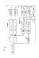
- FIG. 1 is a block diagram of a lighting system including a lighting device according to an embodiment.
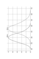
- FIG. 2 is a graph showing the relationship between wavelength and relative value regarding the visual spectral sensitivity characteristics and the visual spectral sensitivity characteristics of the eye sensor that affect biorhythms.
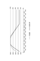
- FIG. 3 is a graph showing an example of the control based on the circadian rhythm performed by the lighting device shown in FIG.
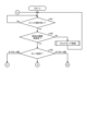
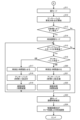
- FIG. 4A is a flowchart (1) of the setting process performed by the control circuit.
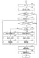
- FIG. 4B is a flowchart (2) of the setting process performed by the control circuit.
- FIG. 4C is a flowchart (3) of the setting process performed by the control circuit.
- FIG. 1 is a block diagram of a lighting system including a lighting device according to an embodiment.
- FIG. 2 is a graph showing the relationship between wavelength and relative value regarding the visual spectral sensitivity characteristics and the visual spectral sensitivity characteristics of the eye sensor that affect biorhythms.
- FIG. 3 is a graph showing an example of the control
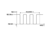
- FIG. 5 is a graph showing the relationship between time and the rectified voltage applied to the input side of the power factor correction circuit in the lighting device when the morning mode is set.
- FIG. 6 is a graph showing the relationship between time and the rectified voltage applied to the input side of the power factor correction circuit in the lighting device when the night mode is set.
- FIG. 7 is a graph showing the relationship between time and the rectified voltage on the input side of the power factor correction circuit applied within the lighting device when adjusting the time addition immediately after setting the morning mode or night mode.
- FIG. 8 is a graph showing the relationship between time and the rectified voltage on the input side of the power factor correction circuit applied within the lighting device when adjusting the time subtraction immediately after setting the morning mode or night mode.
- FIG. 9 is a flowchart of the reset mode process performed by the control circuit.
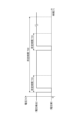
- FIG. 10 is a graph showing the relationship between time and the rectified voltage at the input side of the power factor correction circuit applied in the lighting device in the reset mode.
- FIG. 1 is a block diagram of a lighting system 1 including a lighting device M according to an embodiment.
- the lighting system 1 according to the embodiment includes an AC power supply ACI1, a switch I2, and a lighting device M, for example.
- AC (alternating current power source) I1 supplies power to lighting device M and is electrically connected to switch I2.
- Switch I2 is electrically connected to PFC (power factor correction) M1 and to AC voltage detection circuit M5, which will be described later.
- Switch I2 is provided on a wall of a facility such as an office, school, or hospital, and is switched on and off by pressing it. Turning switch I2 on causes light to be emitted from LED module M4, which will be described later, to light up lighting device M, and turning switch I2 off stops the emission of light from LED module M4, turning off lighting device M.
- the lighting device M is installed, for example, on the ceiling of the facility described above, and includes a PFC (power factor correction circuit) M1, a first DC/DC converter M2, a second DC/DC converter M3, and an LED module M4.
- PFC power factor correction circuit
- the PFC (power factor correction circuit) M1 is a circuit that brings the power factor of the AC (alternating current power source) I1 closer to 1, and is electrically connected to the first DC/DC converter M2 and also electrically connected to the second DC/DC converter M3.
- the PFC (power factor correction circuit) M1 rectifies the input AC voltage to a DC voltage on the input side, and converts the DC voltage to a DC voltage of a predetermined voltage on the output side and outputs it.
- the PFC (power factor correction circuit) M1 may be provided with an insulating circuit or may be a non-insulated circuit system.
- the first DC/DC converter M2 is a circuit that converts the DC voltage input from the PFC (power factor correction circuit) M1 into a voltage required to light the multiple first light sources M41 and outputs a predetermined current to the light sources M41.
- the first DC/DC converter M2 is electrically connected to the first light sources M41.
- the second DC/DC converter M3 is a circuit that converts the DC voltage input from the PFC (power factor correction circuit) M1 into a voltage required to light the multiple second light sources M42 and outputs a predetermined current to the light sources M42.
- the second DC/DC converter M3 is electrically connected to the second light sources M42.
- the LED module M4 includes a plurality of light sources LS, which are arranged, for example, in two dimensions, vertically and horizontally.
- the light sources LS of the LED module M4 are, for example, configured with a plurality of first light sources M41 that emit cool color light and a plurality of second light sources M42 that emit warm color light.
- the LED module M4 is an LED module in which a plurality of first light sources M41 and a plurality of second light sources M42 are mounted on a board.
- the LED module M4 is electrically connected to the AC (alternating current power source) I1 via the switch I2, and includes a plurality of light sources LS that can emit cool color light and warm color light.
- the cool color light emitted from the first light source M41 is, for example, a daylight color of 6500K
- the warm color light emitted from the second light source M42 is, for example, an incandescent color of 2700K.
- the lighting device M also includes an AC voltage detection circuit M5, a control circuit (control unit) M6, a timer circuit M7, and a power storage unit M8.
- the AC voltage detection circuit M5 is a circuit that detects whether power is being supplied to the downstream side of the switch I2, when the AC (alternating current power source) I1 is on the upstream side, and whether the power supply to the downstream side of the switch I2 is cut off.
- the AC voltage detection circuit M5 is electrically connected to the control circuit M6.
- the control circuit M6 has a function of comprehensively controlling each part of the lighting device M according to this embodiment.
- the control circuit M6 is electrically connected to the first DC/DC converter M2, electrically connected to the second DC/DC converter M3, electrically connected to the timer circuit M7, and electrically connected to the power storage unit M8.
- the control circuit M6 has a judgment control unit 21, a mode control unit 22, an adjustment unit 23, a memory unit 24, and a drive control unit 25.
- the control circuit M6 is realized by a computer including a CPU (Central Processing Unit), RAM (Random Access Memory), ROM (Read Only Memory), an input/output interface, and an internal bus.
- CPU Central Processing Unit
- RAM Random Access Memory
- ROM Read Only Memory
- the determination control unit 21 has the function of selecting the morning mode, night mode, or reset mode depending on the number of off/on operations.
- the mode control unit 22 has a function to control the execution of processing in the above three modes (morning, night, reset).
- the mode control unit 22 also has a function to control the selection of a mode (circadian mode, fixed color temperature modes 1 and 2) in the reset mode described below.
- the mode control unit 22 transfers the execution processing to the adjustment unit 23 when the time adjustment mode of the morning mode or night mode is selected.
- the mode control unit 22 transfers the execution processing to the adjustment unit 23 even when the circadian mode of the reset mode is selected.
- the mode control unit 22 instructs the drive control unit 25 to output a fixed color temperature.
- the adjustment unit 23 adjusts the shift time of the circadian rhythm time.
- the adjustment unit 23 resets (returns to the initial setting state) the shift time of the circadian rhythm time.
- the memory unit 24 stores various data.
- a memory unit 24 has a first memory unit 241 and a second memory unit 242.
- the first memory unit 241 stores circadian rhythm information, which is various data such as data related to dimming and color adjustment of a 24-hour (one day) schedule of a circadian rhythm, which will be described later.
- the second memory unit 242 stores data related to the time set as the start time and the adjusted time difference (so-called shift time).
- the drive control unit 25 has a function of driving the multiple light sources LS. More specifically, the drive control unit 25 adjusts the color temperature (toning) by adjusting the ratio between the current value of the first light source M41 to be turned on and the current value of the second light source M42 to be turned on. The drive control unit 25 also adjusts the light quantity (luminous flux quantity) (dimming) by adjusting the sum of the current value of the first light source M41 to be turned on and the current value of the second light source M42 to be turned on. For example, the drive control unit 25 can adjust the color and dimming by adjusting the sum of the current value of the first light source M41 to be turned on and the current value of the second light source M42 to be turned on after setting the ratio to a desired color temperature.
- the current value adjustment method may be either a PWM control method or an amplitude control method.
- the control circuit M6 changes the color temperature and light amount of the light emitted from the LED module M4 over time based on a circadian rhythm described below. Specifically, the control circuit M6 changes the amount of cool color light and warm color light emitted from the LED module M4 over time based on a circadian rhythm described below. More specifically, the control circuit M6 changes the color temperature of the light emitted from the LED module M4 (i.e., adjusts the color) and changes the amount of light emitted from the LED module M4 (i.e., adjusts the dimming) depending on the time of day.
- the timer circuit M7 is, for example, a configuration of a crystal oscillator and a microcomputer or an RTC (Real Time Clock) element, and has the function of continuing to keep time on the timer circuit M7 even when the power supply from the AC (alternating current power source) I1 is cut off.
- the control circuit M6 stores the adjusted time difference between the time set as the first time in the first mode (morning mode) or the second time in the second mode (night mode) and reflects it on the timer circuit M7. Note that in the following description, the morning mode is an example of the first mode, and the night mode is an example of the second mode.
- the power storage unit M8 is, for example, an electric double layer capacitor (supercapacitor), and can store electricity while electrically connected to the AC (alternating current power source) I1. After storing electricity, when the power supply from the AC (alternating current power source) I1 is cut off, the power can be supplied to the timer circuit M7 via the control circuit M6.
- the lighting device M includes a power storage unit M8 that supplies power to the timer circuit M7 continuously for, for example, about 10 days when the power supply from the AC (alternating current power source) I1 is cut off.
- the timer circuit M7 is not reset by the power storage unit M8, even if the AC power source I1 is turned off for a moment and then turned on again.
- Figure 2 is a graph showing the relationship between wavelength and relative value regarding the spectral sensitivity characteristics of vision and the spectral sensitivity characteristics of the eye sensor that affect biological rhythms.
- Figure 3 is a graph showing an example of control based on circadian rhythms performed by the lighting device M shown in Figure 1.
- Circadian rhythms are roughly 24-hour cycles that exist in living organisms, and are also called circadian rhythms. Human circadian rhythms are slightly longer than 24 hours, which can disrupt our daily rhythms, but sunlight or light from lighting devices such as M can adjust the human circadian rhythm to 24 hours, allowing humans to live according to the same rhythm.
- the spectral sensitivity of vision peaks at approximately 555 nm.
- the spectral sensitivity of the eye which affects the circadian rhythm, peaks at approximately 480 nm.
- the synchronization of the body clock by light can only be achieved in the suprachiasmatic nucleus, and the mechanism is that when nerve cells in the retina of the eye are exposed to light of 480 nm and several thousand lux, the signal is carried to the suprachiasmatic nucleus of the hypothalamus, and this signal causes the Per1 gene transcription to be enhanced, thereby adjusting the body clock.
- the lighting device M adjusts the human circadian rhythm to 24 hours by emitting more short-wavelength cool-colored light from the LED module M4 in the morning (first time period) than long-wavelength warm-colored light, and emitting more long-wavelength warm-colored light from the LED module M4 in the evening (second time period) than short-wavelength cool-colored light, as shown in FIG. 3.
- the lighting device M changes the color temperature according to the time of day, while changing the amount of light (i.e., luminous flux value) emitted from the LED module M4 according to the time of day. Therefore, the LED module M4 according to this embodiment adjusts the human circadian rhythm to 24 hours by changing the color temperature (color adjustment) and the amount of light (dimming) according to the time of day.
- the lighting device M according to this embodiment shows a case where the starting point is, for example, 6:00.
- the control circuit M6 causes the LED module M4 to emit light with a color temperature of approximately 2700K at 6 o'clock, and with an amount of light that is 30% of the maximum amount of light emitted by the LED module M4.
- the control circuit M6 controls the LED module M4 to emit light such that the color temperature changes from 2700K to 5000K and the light intensity of the LED module M4 changes from 30% to 100% between 6:00 and 10:00.
- the control circuit M6 controls the LED module M4 to emit light so that the color temperature is maintained at 5000K and the amount of light emitted from the LED module M4 is maintained at 100% from 10:00 to 13:30.
- the control circuit M6 controls the LED module M4 to emit light such that the color temperature changes from 5000K to 2700K between 1:30pm and 8:30pm. After 8:30pm, the control circuit M6 controls the LED module M4 to emit light such that the color temperature remains at 2700K until 6am the following morning.
- the control circuit M6 causes the LED module M4 to emit light so that the amount of light emitted from the LED module M4 is maintained at 100% from 1:30 pm to 2:30 pm.
- the control circuit M6 then causes the LED module M4 to emit light so that the amount of light emitted from the LED module M4 changes from 100% to 30% from 2:30 pm to 9:30 pm.
- the control circuit M6 also causes the LED module M4 to emit light after 9:30 pm so that the amount of light emitted from the LED module M4 is maintained at 30% until 6:00 am the following morning. In other words, the control circuit M6 causes the LED module M4 to emit light so that the amount of light emitted from the LED module M4 is minimized after 9:30 pm.
- the lighting device M when the lighting device M emits light from the LED module M4 based on the circadian rhythm, the light source M41 that emits cool color light predominates in the morning, and the current-time product flowing through the light source M42 that emits warm color light is smaller than that of the light source M41 that emits cool color light.
- the light source M42 that emits warm color light At night, the light source M42 that emits warm color light predominates, but since the amount of light emitted from the LED module M4 is smaller than in the morning, the current-time product of the light source M41 that emits cool color light throughout the day is larger than that of the light source M42 that emits warm color light.
- the current-time product affects the lifespan of the LED (i.e., the light source LS). In other words, the larger the current-time product, the sooner the LED will reach the end of its life.
- the light sources M41 emitting cool color light will approach the end of their life sooner, causing a decrease in the luminous flux value of the light sources M41 emitting cool color light before the end of the life of the light sources M42 emitting warm color light, and the lighting device M will no longer be able to provide lighting based on the circadian rhythm.
- the light source M41 that emits cool color light and the light source M42 that emits warm color light of the LED module M4 of this embodiment are set so that their daily current-hour products are the same.
- the color temperature characteristics of the light source M41 emitting cool color light are set higher than the maximum color temperature in the circadian rhythm.
- the maximum color temperature in the circadian rhythm is 5000 K, so for example, the color temperature characteristics of the light source M41 emitting cool color light are set to 6500 K.
- the color temperature characteristics of the light source M41 emitting cool color light are set to 6500 K.
- the light source M41 that emits cool color light By increasing the color temperature of the light source M41 that emits cool color light above the maximum color temperature in the circadian rhythm, it is possible to change the balance of the current values flowing through the light source M41 that emits cool color light and the light source M42 that emits warm color light when emitting light based on the circadian rhythm from the LED module M4, thereby adjusting the daily current-time product of the light source M41 that emits cool color light and the light source M42 that emits warm color light to be the same, thereby extending the life of the lighting device M.
- the lighting device M automatically changes the color temperature (color adjustment) and light intensity (dimming) according to the time of day using the control circuit M6, and adjusts the human circadian rhythm to 24 hours by emitting light from the LED module M4 that is similar to that experienced under sunlight.
- Figures 4A, 4B, and 4C are flowcharts of the setting process performed by the control circuit M6.
- control circuit M6 determines whether or not, for example, switch I2 has been operated (step S01). If the control circuit M6 has not detected the operation of switch I2 (step S01: No), it waits until it detects the operation of switch I2, whereas if it detects the operation of switch I2 (step S01: Yes), it proceeds to step S02.
- step S02 determines whether the time for morning mode or night mode has not been adjusted. If the time for morning mode or night mode has been adjusted (step S02: No), the control circuit M6 performs a determination process for the reset mode process described below. On the other hand, if the time for morning mode or night mode has not been adjusted (step S02: Yes), the control circuit M6 proceeds to step S03.
- the control circuit M6 judges whether the switch I2 has been operated to set a mode (step S03). Specifically, the control circuit M6 detects the number of times the switch I2 is turned on and off during a predetermined period of time to judge what mode setting has been selected. If the number of times the switch I2 is turned on and off during a predetermined period of time is three (step S03:B), the control circuit M6 proceeds to step 11 shown in FIG. 4B. If the number of times the switch I2 is turned on and off during a predetermined period of time is four (step S03:C), the control circuit M6 proceeds to step S31 shown in FIG. 4C. If the number of times the switch I2 is turned on and off during a predetermined period of time is neither three nor four (step S03:A), the control circuit M6 returns to step 01.
- step S11 the switch I2 is turned off and on three times during the specified time period (step S03:B) and the mode transitions to morning mode will be described with reference to FIG. 4B.
- the control circuit M6 proceeds to set the morning mode (step S11), and then starts displaying an answerback indicating that the morning mode has been set (turning on the first light source M41, which is a cool color, for 30 seconds) (step S12).
- the control circuit M6 judges whether or not the switch I2 is turned on or off during the predetermined time (30 seconds) during which the answerback is turned on (step S13). If the control circuit M6 detects the switch I2 being turned on or off (step S13: Yes), it transitions to the time adjustment mode (step S14) and stops the display of the answerback (turning off the first light source M41 of cool colors). On the other hand, if the control circuit M6 does not detect the switch I2 being turned on or off (step S13: No), it proceeds to step S23.
- the control circuit M6 starts the stopwatch and determines whether a predetermined time (e.g., 3 minutes) has not elapsed (step S15). If the stopwatch indicates that the predetermined time has not elapsed (step S15: Yes), the control circuit M6 proceeds to step S16. On the other hand, if the stopwatch indicates that the predetermined time has not elapsed, that is, if the predetermined time has elapsed (step S15: No), the control circuit M6 proceeds to step S23.
- a predetermined time e.g., 3 minutes
- step S16 the control circuit M6 performs an off-on pulse determination. More specifically, if the switch I2 has been turned off and on once, the control circuit M6 proceeds to step S17, and if the switch I2 has been turned off and on twice, the control circuit M6 proceeds to step S20.
- step S17 the control circuit M6 delays the time of the first period by one hour (step S17), and displays an answerback display, for example by turning on the second light source M42 once every two seconds to indicate that the time has been delayed (step S18), and subtracts one hour from the first period in the morning mode, i.e., adjusts the time to be delayed by one hour (step S19).
- step S19 the control circuit M6 returns to step S15 and determines whether a predetermined time (for example, three minutes) has not yet elapsed.
- step S20 the control circuit M6 advances the time of the first period by one hour (step S20), and to indicate that the time has been advanced, displays an answerback display, for example by turning on the first light source M41 twice in three seconds (step S21), and adds one hour to the first period of the morning mode, i.e., adjusts the time to advance by one hour (step S22).
- step S21 the control circuit M6 then returns to step S15 and determines whether a predetermined time (for example, three minutes) has not yet elapsed.
- step S15 when a predetermined time has elapsed on the stopwatch (step S15: No), the control circuit M6 confirms the first time for the morning mode (step S23).
- control circuit M6 stores the time set as the start time and the adjusted time difference, adjusts the time to reflect this on the time on the timer circuit M7 (step S24), and then ends this setting process.
- step S31 the switch I2 is turned off and on four times during the specified time period
- step S32 the night mode has been entered
- control circuit M6 determines whether or not the switch I2 is turned on or off during the predetermined time (30 seconds) during which the answerback is turned on (step S33). If the control circuit M6 detects the switch I2 being turned on or off (step S33: Yes), it transitions to time adjustment mode (step S34) and stops displaying the answerback (turning off the warm-colored second light source M42). On the other hand, if the control circuit M6 does not detect the switch I2 being turned on or off, it proceeds to step S43 (step S33: No).
- the control circuit M6 starts the stopwatch and determines whether a predetermined time (e.g., 3 minutes) has not elapsed (step S35). If the stopwatch indicates that the predetermined time has not elapsed (step S35: Yes), the control circuit M6 proceeds to step S36. On the other hand, if the stopwatch indicates that the predetermined time has not elapsed, i.e., if the predetermined time has elapsed (step S35: No), the control circuit M6 proceeds to step S43.
- a predetermined time e.g. 3 minutes
- step S36 the control circuit M6 performs an off-on pulse determination. More specifically, if the switch I2 has been turned off and on once, the control circuit M6 proceeds to step S37, and if the switch I2 has been turned off and on twice, the control circuit M6 proceeds to step S40.
- step S37 the control circuit M6 delays the second time by one hour (step S37), and to indicate that the time has been delayed, displays an answerback message by, for example, lighting the second light source M42 once every two seconds (step S38), and subtracts one hour from the second time in night mode, i.e., adjusts the time to be delayed by one hour (step S39). After that, the control circuit M6 returns to step S35 and determines whether the predetermined time (for example, three minutes) has not yet elapsed.
- the predetermined time for example, three minutes
- step S40 the control circuit M6 advances the time of the second time by one hour (step S40), and to indicate that the time has been advanced, for example, an answerback display is displayed by turning on the first light source M41 twice in three seconds (step S41), and one hour is added to the second time in night mode, that is, the time is adjusted to advance by one hour (step S22).
- step S41 an answerback display is displayed by turning on the first light source M41 twice in three seconds
- step S41 one hour is added to the second time in night mode, that is, the time is adjusted to advance by one hour (step S22).
- step S22 the control circuit M6 returns to step S35 and determines whether or not a predetermined time (for example, three minutes) has not yet elapsed.
- control circuit M6 stores the time set as the start time and the adjusted time difference, adjusts the time to reflect this on the time on the timer circuit M7 (step S44), and then ends this setting process.
- the morning mode of lighting device M which sets the color temperature and the time for controlling the light amount based on the circadian rhythm in a first time period
- the night mode which sets the color temperature and the time for controlling the light amount based on the circadian rhythm in a second time period.
- Figure 5 is a graph showing the relationship between time and the rectified voltage applied to the input side of the power factor correction circuit (PFC) M1 in the lighting device M when the morning mode is set.
- Figure 6 is a graph showing the relationship between time and the rectified voltage applied to the input side of the power factor correction circuit (PFC) M1 in the lighting device M when the night mode is set.
- the morning mode is a mode in which the color temperature and light intensity control time based on the circadian rhythm are set starting from a first time in a first time period
- the night mode is a mode in which the color temperature and light intensity control time based on the circadian rhythm are set starting from a second time in a second time period.
- the first time period is, for example, 8:00 to 20:00
- the second time period is, for example, 20:00 to 8:00, with half of the 24 hours set as the first time period and the remaining half of the 24 hours set as the second time period.
- a third and fourth mode may be added to divide the 24 hours into four, but for ease of understanding, the morning mode and night mode will be described here with the start time of the morning mode time period as the first time period and the start time of the night mode time period as the second time period.
- the setting of the morning mode shown in FIG. 5 corresponds to the processing of step S03:B in FIG. 4A
- the setting of the night mode shown in FIG. 6 corresponds to the processing of step S03:C in FIG. 4A.
- the control circuit M6 initially sets at least the morning mode or the night mode when the switch I2 is turned off and on a preset number of times within a preset time T1. More specifically, when the switch I2 is turned off and on within a preset short period of time, the power supply state and the cut-off state from the AC (alternating current power source) I1 are switched, so the control circuit M6 detects the on/off operation of the switch I2 using the AC voltage detection circuit M5 and recognizes it as an input operation from the user based on that.
- the control circuit M6 of this embodiment recognizes it as an input operation from the user based on a combination of the period during which power is supplied from the AC (alternating current power source) I1 and the period during which the power supply from the AC (alternating current power source) I1 is cut off through the AC voltage detection circuit M5 based on the operation of the switch I2.
- the morning mode is, for example, a setting for morning (first time period) as an initial setting performed by the lighting system 1
- the night mode is, for example, a setting for night (second time period) as an initial setting performed by the lighting system 1.
- the control circuit M6 transitions to the selection mode for a preset predetermined time T1 from when the switch I2 is turned off.
- the predetermined time T1 for the selection mode is, for example, 5 seconds.
- the control circuit M6 transitions to the morning mode when the switch I2 is turned off and on three times while power is being supplied from the AC (alternating current power source) I1, as shown in FIG. 5 for example.
- the control circuit M6 transitions to the morning mode when, for example, there are three alternating periods in which power is supplied from the AC power source I1 and three periods in which the power supply from the AC power source I1 is cut off.
- the control circuit M6 transitions to the night mode when the switch I2 is turned off and on four times while power is being supplied from the AC power source I1, as shown in FIG. 6 for example.
- the control circuit M6 transitions to the night mode when, for example, a period in which power is supplied from the AC (alternating current power source) I1 and a period in which the supply of power from the AC (alternating current power source) I1 is cut off alternately four times.
- the control circuit M6 transitions to the reset mode when a period in which power is supplied from the AC power source I1 and a period in which the supply of power from the AC power source I1 is cut off alternately five times. While transitioning to the morning mode or night mode is the initial setting, the reset mode is a mode in which an operation to reset that occurs.
- control circuit M6 When the control circuit M6 recognizes the mode setting based on the user's on/off operation of switch I2, it displays an output (answerback) corresponding to the mode by lighting up a specified light source LS.
- the control circuit M6 turns off all light sources LS, then turns on the first light source M41, and indicates that the morning mode is set by illuminating cool color light from the first light source M41 for a maximum of 30 seconds.
- the control circuit M6 then turns on the light source LS with the color temperature and light intensity corresponding to the set time.
- the control circuit M6 turns off all light sources LS, then turns on the second light source M42, and indicates that night mode has been set by illuminating warm-colored light from the second light source M42 for a maximum of 30 seconds. After that, the control circuit M6 turns on the light source LS with the color temperature and light intensity corresponding to the set time.
- Fig. 7 is a graph showing the relationship between time and the rectified voltage applied to the input side of the power factor correction circuit (PFC) M1 in the lighting device M when adjusting the time by adding immediately after setting the morning mode or night mode.
- Fig. 8 is a graph showing the relationship between time and the rectified voltage applied to the input side of the power factor correction circuit (PFC) M1 in the lighting device M when adjusting the time by subtracting immediately after setting the morning mode or night mode.
- the time adjustment immediately after the mode is set as shown in FIG. 7 corresponds to performing steps S14-S16 and steps S20-S22 in FIG. 4B twice.
- control circuit M6 transitions to the time adjustment mode for a preset predetermined time T22 (3 minutes in this embodiment) from when switch I2 is turned off (corresponding to steps S14 and S15 in FIG. 4B).
- the predetermined time T22 for the time adjustment mode is, for example, 3 minutes.
- control circuit M6 transitions to operation reception mode (corresponding to step S16 in FIG. 4B) for a preset predetermined time T21 from when switch I2 is turned off.
- the predetermined time T21 for the operation reception mode is, for example, 2 seconds.
- the control circuit M6 adds one hour to the first time if, for example, the switch I2 is turned off and on twice during a predetermined time T21 (corresponding to steps S20-S22 in FIG. 4B).
- the control circuit M6 makes the current time of the timer circuit M7 one hour earlier than the first time if, for example, there are two alternating periods in which power is supplied from the AC (alternating current power source) I1 and two periods in which the supply of power from the AC (alternating current power source) I1 is cut off.
- control circuit M6 When the control circuit M6 recognizes an operation to advance the first time by one hour based on the user's on/off operation of switch I2, it displays an output (answerback) corresponding to that operation by blinking and lighting a specific light source LS (corresponding to step S21 in FIG. 4B).
- control circuit M6 when the control circuit M6 recognizes an operation to advance the first time by one hour based on the user's on/off operation of the switch I2, it turns off all the light sources LS and then lights up one set of the first light source M41, which emits cool color light, by blinking twice every three seconds.
- the control circuit M6 determines that the time has advanced two hours from the first time, and turns on the first light source M41, which emits cool colored light, in two sets, with one set being a blinking twice every three seconds.
- the time on the timer circuit M7 is advanced by two hours from the first time of 8 o'clock, and the time on the timer circuit M7 is changed to 10 o'clock (corresponding to step S24 in FIG. 4B). Furthermore, in the lighting device M of this embodiment, the control circuit M6 stores the time difference between the time set as the first time and the current time on the timer circuit M7. For example, when the first time at the present time is 8 o'clock, the first time is set to 10 o'clock based on the above operation. Therefore, the time on the timer circuit M7 in the circadian rhythm control shown in FIG. 3 is the first time plus two hours.
- control circuit M6 changes the first time according to the number of operations of the switch I2 in a predetermined time immediately after setting the morning mode, and starts the control of the color temperature and light amount based on the circadian rhythm, starting from the time after the start of the stopwatch (the time after the predetermined time T22 has elapsed).
- the second memory unit 242 stores the start time of 10 o'clock and the adjusted time difference (so-called shift time) of 2 hours, and the time on the timer circuit M7 is set to 10 o'clock.
- the time on the timer circuit M7 is set to 8 o'clock, and regardless of the current time, control based on the circadian rhythm begins from the current time with the color temperature and luminous flux ratio of 8 o'clock shown in Figure 3.
- the time adjustment immediately after the mode is set as shown in FIG. 8 corresponds to performing steps S34 to S39 in FIG. 4C twice.
- the control circuit M6 transitions to the time adjustment mode (corresponding to steps S34 and S35 in FIG. 4C) for a preset predetermined time T22 (3 minutes in this embodiment) from when switch I2 is turned off.
- the predetermined time T22 for the time adjustment mode is, for example, 3 minutes.
- control circuit M6 transitions to operation reception mode (corresponding to step S36 in FIG. 4C) for a preset predetermined time T21 from when switch I2 is turned off.
- the predetermined time T21 for the operation reception mode is, for example, 2 seconds.
- the control circuit M6 When delaying the current time of the timer circuit M7 by one hour from the second time, the control circuit M6 subtracts one hour from the second time when, for example, the switch I2 is turned off and on once during the specified time T21 (corresponding to steps S37-S39 in FIG. 4C). In other words, the control circuit M6 causes the current time of the timer circuit M7 to be one hour later than the second time when, for example, there is a period in which power is supplied from the AC (alternating current power source) I1 and a period in which the supply of power from the AC (alternating current power source) I1 is cut off.
- control circuit M6 If the control circuit M6 recognizes an operation to delay the second time by one hour based on the user's on/off operation of switch I2, it displays an output (answerback) corresponding to that operation by blinking and lighting a specific light source LS (corresponding to step S38 in FIG. 4C).
- control circuit M6 when the control circuit M6 recognizes an operation to delay the second time by one hour based on the user's on/off operation of the switch I2, it turns off all the light sources LS and then lights up one set of the second light source M42, which emits warm color light, with one set being a blinking cycle once every two seconds.
- the control circuit M6 since the time has now been delayed by two hours from the second time, lights up the second light source M42, which emits warm colored light, in two sets, with one set being a blinking once every two seconds.
- the time on the timer circuit M7 is delayed by two hours from the second time of 20:00, and the time on the timer circuit M7 is changed to 18:00 (corresponding to step S44 in FIG. 4C). Furthermore, in the lighting device M of this embodiment, the control circuit M6 stores the time difference between the time set as the second time and the current time of the timer circuit M7. For example, when the second time at the current time is 20:00, the second time is set to 18:00 based on the above operations. Therefore, the time on the timer circuit M7 in the circadian rhythm control shown in FIG. 3 is the time obtained by subtracting two hours from the second time.
- control circuit M6 changes the second time according to the number of operations of the switch I2 in a predetermined time immediately after the night mode is set, and starts the control of the color temperature and the light amount based on the circadian rhythm, starting from the time after the stopwatch has started (the time after the predetermined time T22 has elapsed).
- the second memory unit 242 stores the set start time of 18:00 and the adjusted time difference (so-called shift time) of 2 hours, and the time on the timer circuit M7 is set to 18:00.
- control based on the circadian rhythm begins from the current time with the color temperature and luminous flux ratio of 18:00 shown in Figure 3.
- the time on the timer circuit M7 is set to 20:00, and regardless of the current time, control based on the circadian rhythm begins from the current time with the color temperature and luminous flux ratio of 20:00 shown in Figure 3.
- switch I2 When delaying the first time, switch I2 is operated in the same way as when delaying the second time described with reference to FIG. 8, and when advancing the second time, switch I2 is operated in the same way as when advancing the first time described with reference to FIG. 7. Therefore, by performing the operations in FIG. 7 or FIG. 8 a maximum of six times, it is possible to adjust the time in one-hour increments over a 24-hour period. It is also possible to adjust the time to an accuracy of within ⁇ 30 minutes of the true time.
- control circuit M6 indicates, as an answerback, how many hours the first time has been changed by lighting a cool colored light twice every three seconds or once every two seconds, and how many sets of warm colored light twice every three seconds or once every two seconds, as one set, how many hours the second time has been changed. Furthermore, the control circuit M6 sets the blinking pattern to twice every three seconds when the first time or the second time is advanced, and sets the blinking pattern to once every two seconds when the first time or the second time is delayed. In other words, the control circuit M6 clearly changes the blinking pattern depending on whether the time is advanced or delayed.
- the control circuit M6 lights the light source LS a number of times according to the changed time, and indicates by the blinking pattern whether the light flashes twice every three seconds or once every two seconds, depending on whether the first time or the second time has been advanced or delayed. In other words, the control circuit M6 changes the number of times the light is turned on and the blinking pattern according to the changed time.
- switch I2 is turned off and light intensity control based on the circadian rhythm is interrupted.
- timer circuit M7 continues to operate without stopping due to the power supply from power storage unit M8.
- switch I2 is turned on and power supply from AC (alternating current power source) I1 is resumed, control of color temperature and light intensity based on the circadian rhythm is resumed, and at the point in time when power supply from AC (alternating current power source) I1 is resumed, control circuit M6 resumes control of color temperature and light intensity based on the circadian rhythm according to the time on timer circuit M7.
- timer circuit M7 is still operating, so control will resume at the color temperature and light intensity based on the circadian rhythm that corresponds to "9:30 p.m.”
- FIG. 9 is a flowchart of the reset mode processing performed by the control circuit M6.
- the control circuit M6 performs a reset mode determination to determine whether or not the reset mode has been set (step S50). More specifically, the control circuit M6 determines, for example, whether or not the switch I2 has been turned off and on five times. If the control circuit M6 has not detected five off and on operations of the switch I2 (step S50: No), it waits until it detects five off and on operations of the switch I2. In the standby state, the control circuit M6 continues to control the light source LS based on the currently set mode.
- control circuit M6 detects five ON/OFF operations of the switch I2 (step S50: Yes), it starts a stopwatch and determines whether or not a predetermined time (e.g., 25 seconds) has not elapsed (step S51). If the stopwatch indicates that the predetermined time has not elapsed, that is, if the predetermined time has elapsed (step S51: No), the control circuit M6 proceeds to step S62.
- a predetermined time e.g. 25 seconds
- step S51 if the stopwatch indicates that the predetermined time has not yet elapsed (step S51: Yes), the control circuit M6 initializes the mode and time adjustment values (step S52) and returns the circadian mode to the initial setting state (step S53).
- control circuit M6 displays an answerback message saying "Light source LS will not blink” to indicate that the device has transitioned to the initialized circadian mode (step S54), and determines whether the switch I2 has been turned on or off (step S55).
- step S55: No If the control circuit M6 does not detect the switch I2 being turned on or off in step S55 (step S55: No), the control circuit M6 returns to step S51 and determines whether 25 seconds have passed. On the other hand, if the control circuit M6 detects the switch I2 being turned on or off in step S55 (step S55: Yes), the control circuit M6 transitions to color temperature fixed mode 1 (step S56). Then, to indicate that the control circuit M6 has transitioned to color temperature fixed mode 1, the control circuit M6 performs an answerback display, for example, by blinking the light source LS once every two seconds (step S57), and determines whether the switch I2 being turned on or off is detected (step S58).
- step S57 determines whether the switch I2 being turned on or off is detected
- step S58: No If the control circuit M6 does not detect the switch I2 being turned on or off in step S58 (step S58: No), the control circuit M6 returns to step S51 and determines whether 25 seconds have passed. On the other hand, if the control circuit M6 detects the switch I2 being turned on or off in step S58 (step S58: Yes), the control circuit M6 transitions to color temperature fixed mode 2 (step S59), and to indicate that the control circuit M6 has transitioned to color temperature fixed mode 2, the control circuit M6 performs an answerback display, for example, by blinking the light source LS twice in three seconds (step S60), and determines whether the switch I2 being turned on or off is detected (step S61).
- step S60 determines whether the switch I2 being turned on or off is detected
- control circuit M6 detects in step S61 that switch I2 is off or on (step S61: Yes), it returns to step S53, cancels the setting of color temperature fixed mode 2, returns to the initial setting of the circadian mode, and continues the processing from step S54 onwards.
- step S61 determines whether 25 seconds have elapsed.
- step S51 If 25 seconds have elapsed (step S51: No), the control circuit M6 confirms the mode setting (step S62) and ends the reset mode process.
- FIG. 10 is a graph showing the relationship between the rectified voltage applied to the input side of the power factor correction circuit (PFC) M1 in the lighting device M and time in the reset mode.
- PFC power factor correction circuit
- the control circuit M6 transitions to the reset mode. For example, the control circuit M6 transitions to the reset mode when the switch I2 is turned off and on five times while power is being supplied from the AC (alternating current power source) I1. In other words, the control circuit M6 transitions to the reset mode when, for example, there are five alternating periods in which power is supplied from the AC (alternating current power source) I1 and five periods in which the power supply from the AC (alternating current power source) I1 is cut off.
- the predetermined time T31 is 5 seconds, the same specified time as T1 in Figures 5 and 6.
- the control circuit M6 When switching to the reset mode, the control circuit M6 resets the morning mode or night mode setting and the time adjustment value adjusted in the morning mode or night mode. In other words, the mode switches to the initialized circadian mode.
- "T33-T31" shown in FIG. 10 is the "25 seconds” described in the flowchart of FIG. 9.
- the predetermined time T32 is, for example, 2 seconds.
- fixed color temperature mode 1 the lamp is always lit with a light amount set at a color temperature that is balanced between the lifespan determined by the current-time product of the first light source M41 that emits cool color light, such as 4000K, and the second light source M42 that emits warm color light, and the working efficiency determined by the color temperature in actual use.
- This fixed color temperature mode 2 is, for example, a mode in which the light amount is further changed than fixed color temperature mode 1.
- the mode is switched in order to circadian mode, color temperature fixed mode 1, and color temperature fixed mode 2.
- An example of the answerback setting when switching between modes may be, for example, no flashing in circadian mode, one flashing every two seconds in color temperature fixed mode 1, and two flashing every three seconds in color temperature fixed mode 2.
- the set mode i.e., either circadian mode, color temperature fixed mode 1, or color temperature fixed mode 2 is confirmed.
- the predetermined time T33 is, for example, 30 seconds. After that, selection of morning mode or night mode and adjustment of the time can be accepted only in circadian mode.
- the lighting device M according to the embodiment described above has been described as having two modes, a morning mode and a night mode, in a 24-hour period, but it may have one mode or three or more modes in a 24-hour period, for example.
- the lighting device M includes a light source LS electrically connected to an AC (alternating current power source) I1 via a switch I2, and a control circuit (control unit) M6 that changes the color temperature and light intensity of the light emitted from the light source LS over time based on the circadian rhythm, and the control circuit M6 sets the time for controlling the color temperature and light intensity based on the circadian rhythm according to the number of times the switch IS is operated within a predetermined period of time. Therefore, the lighting device M according to this embodiment can set the time for controlling the color temperature and light intensity based on the circadian rhythm according to the number of times the switch I2 is operated within a predetermined period of time, so there is no need to provide a dedicated remote control device.
- the lighting device M that provides lighting based on the circadian rhythm can be provided at a low price, and the introduction of the lighting device M can be simplified.
- lighting devices that can adjust the brightness and color of the light wirelessly using a mobile terminal such as a smartphone have been sold, but detailed settings are required to adjust the brightness and color of the light based on the circadian rhythm in the lighting device.
- the setting for pairing the lighting device with a mobile terminal is complicated, and it is also complicated to prepare a registered mobile terminal.
- the lighting device M according to the present embodiment does not need to be paired with a mobile terminal, does not need a registered mobile terminal, and does not have the problem of radio wave interference caused by wireless.
- the lighting device M when a circadian rhythm is realized using a control system that controls the light intensity of the cool color LEDs and the warm color LEDs with PWM signals using a wired remote control, a control system that controls each with a 0-10V signal, or a control system using a DALI (registered trademark) system that controls both at once, the control system is expensive, specialized knowledge is required for initial setting, and the construction costs are high because of the wired remote control.
- the lighting device M according to the present embodiment can change the start time of the morning mode or the night mode regardless of the current time, and the time setting operation can be easily performed. Furthermore, the lighting device M according to this embodiment can shift the mode by 12 hours by operating the switch in two modes six times to advance or six times to delay, so time adjustment can be performed with a small number of operations.
- the lighting device M has a first mode for controlling the color temperature and light intensity based on the circadian rhythm in a first time period, and a second mode for controlling the color temperature and light intensity based on the circadian rhythm in a second time period, and the control circuit M6 transitions to the first mode or the second mode depending on the number of times the switch I2 is operated within a given period. Therefore, the lighting device M according to this embodiment can divide 24 hours into two, the first mode and the second mode, making it easy to set the time.
- the control circuit M6 adjusts the time in the first time period according to the number of times the switch I2 is operated within a specified period after transitioning to the first mode, and starts controlling the color temperature and light intensity based on the circadian rhythm with the adjusted time as the start time, and adjusts the time in the second time period according to the number of times the switch I2 is operated within a specified period after transitioning to the second mode, and starts controlling the color temperature and light intensity based on the circadian rhythm with the adjusted time as the start time.
- the control circuit M6 sets, as a first mode, a mode in which the color temperature and light intensity are controlled based on a circadian rhythm with a start time being a first time in a first time period, or sets, as a second mode, a mode in which the color temperature and light intensity are controlled based on a circadian rhythm with a start time being a second time period in a second time period.
- control circuit M6 changes the first time in accordance with the number of times the switch I2 is operated within a predetermined period immediately after the first mode is set, and controls the color temperature and light intensity based on a circadian rhythm with a start time being the adjusted time, or changes the second time in accordance with the number of times the switch I2 is operated within a predetermined period immediately after the second mode is set, and controls the color temperature and light intensity based on a circadian rhythm with a start time being the adjusted time.
- the first time is the time after adjustment in the first mode or a preset initial setting time
- the second time is the time after adjustment in the second mode or a preset initial setting time
- the control circuit M6 turns on the light source LS a number of times according to the changed time, and changes the blinking pattern according to whether the first time or the second time has been advanced or delayed. Therefore, the lighting device M according to this embodiment allows the user to easily determine whether the operation performed by the user has been properly input to the lighting device M, based on the blinking pattern of the light source LS and the number of times it is repeated.
- the lighting device M further includes a timer circuit M7.
- the control circuit M6 stores the time difference between the start time and the time set, and reflects this difference in the time on the timer circuit M7.
- the lighting device M according to this embodiment further includes a power storage unit M8 that supplies power to the timer circuit M7 when the power supply from the AC (alternating current power source) I1 is cut off. Furthermore, when the power supply from the AC (alternating current power source) I1 is resumed, the control circuit M6 resumes control of the color temperature and light intensity based on the circadian rhythm according to the time of the timer circuit M7. Therefore, the lighting device M according to this embodiment can perform lighting control of the color temperature and light intensity based on the circadian rhythm even after the power supply from the AC (alternating current power source) I1 is cut off.
- the control circuit M6 transitions to the reset mode when the time adjustment is set to morning mode or night mode and the number of times switch I2 has been operated is a predetermined number of times. Therefore, the lighting device M according to this embodiment can be made so that after the time has been adjusted, the time cannot be readjusted unless the device goes through the reset mode.
- switch I2 By increasing the complexity of the operation of switch I2 for time readjustment, it is possible to prevent erroneous adjustment of the time due to erroneous operation of switch I2.
- the light source LS includes a first light source M41 that emits cool color light and a second light source M42 that emits warm color light, and the first light source M41 emits light with a color temperature higher than the maximum color temperature in the circadian rhythm. This makes it possible to extend the expected life of the lighting device M.
- the number of times the switch I2 is turned on and off is merely an example, and can be changed to an appropriate number as necessary.
- the light source LS has been described as including a plurality of first light sources M41 that emit cool color light and a plurality of second light sources M42 that emit warm color light.
- the light source LS according to this embodiment is not limited to this.
- the light source LS may include a plurality of first light sources that emit blue light, a plurality of second light sources that emit red light, and a plurality of third light sources that emit green light.
- the light source LS is not limited to these, and may be any light source that can change the color temperature and light amount of the light over time.
- I1 AC AC power supply
- I2 switch LS light source
- M lighting device M6 control circuit (control unit)
Landscapes
- Circuit Arrangement For Electric Light Sources In General (AREA)
Abstract
照明装置(M)は、スイッチ(I2)を介して電源(I1)に対して電気的に接続された光源(LS)と、サーカディアンリズムに基づいて、前記光源(LS)から出射される光の色温度と光量とを経時的に変化させる制御部(M6)と、を備える。前記制御部(M6)は、前記スイッチ(I2)の所定時間の操作回数に応じて、サーカディアンリズムに基づく色温度と光量の制御に関する時刻設定を行う。
Description
本発明は、照明装置および照明装置の時刻設定方法に関する。
従来の照明装置の中には、相互に色温度が異なる第1発光装置による光、および、第2発光装置による光の照射割合を、1日のうちの時間帯に応じて変化させる、いわゆるサーカディアンリズムに基づく照明を行うものがある(例えば、特許文献1)。
また、サーカディアンリズムに基づく照明を行う照明装置の中には、発光装置から照射される特定の色温度の光量を変更し、かつ、点灯する時間を変更する専用のリモートコントロール装置を設けるものがある。
しかしながら、サーカディアンリズムに基づく照明を行う照明装置に、専用のリモートコントロール装置を設ける場合、または、有線による専用の制御システムを導入する場合には、専用の装置が高価であること、または、専門知識を有する作業員が初期設定を行うことにより費用が掛かることに起因して、初期設定費用が高価となり、かつ、照明装置の導入が複雑になる問題があった。
本発明は、上記に鑑みてなされたものであって、サーカディアンリズムに基づく照明を行う照明装置を安価に提供し、かつ、照明装置の導入を簡単にすることにある。
上述した課題を解決し、目的を達成するために、本発明に係る照明装置は、スイッチを介して電源に対して電気的に接続された光源と、サーカディアンリズムに基づいて、前記光源から出射される光の色温度と光量とを経時的に変化させる制御部と、を備える。前記制御部は、前記スイッチの所定時間の操作回数に応じて、サーカディアンリズムに基づく色温度と光量の制御に関する時刻設定を行う。
本発明に係る照明装置の一態様によれば、サーカディアンリズムに基づく照明を行う照明装置を安価に提供することができると共に、照明装置の導入を簡単にすることができる。
以下に、実施形態に係る照明装置Mを図面に基づいて詳細に説明する。なお、図面における各要素の寸法の関係、各要素の比率などは、現実と異なる場合がある。図面の相互間においても、互いの寸法の関係や比率が異なる部分が含まれている場合がある。
[実施形態]
図1は、実施形態に係る照明装置Mを有する照明システム1のブロック図である。実施形態に係る照明システム1は、例えば、交流電源であるACI1と、スイッチI2と、照明装置Mと、を備える。
図1は、実施形態に係る照明装置Mを有する照明システム1のブロック図である。実施形態に係る照明システム1は、例えば、交流電源であるACI1と、スイッチI2と、照明装置Mと、を備える。
AC(交流電源)I1は、照明装置Mに電力を供給するものであり、スイッチI2に対して電気的に接続される。そして、スイッチI2は、PFC(power factor correction)M1に対して電気的に接続され、かつ、後述するAC電圧検出回路M5に対して電気的に接続される。また、スイッチI2は、例えば、オフィスや学校、病院などの施設の壁に設けられ、押圧操作によって、オンとオフとが切り替わる。そして、スイッチI2をオンすることによって、後述するLEDモジュールM4から光が出射されることで照明装置Mが点灯し、スイッチI2をオフすることによって、LEDモジュールM4からの光の出射が停止されることで照明装置Mが消灯する。
照明装置Mは、例えば、上述した施設の天井に設置され、PFC(力率改善回路)M1と、第1DC/DCコンバータM2と、第2DC/DCコンバータM3と、LEDモジュールM4と、を備える。
PFC(力率改善回路)M1は、AC(交流電源)I1の力率を1に近づける回路であり、第1DC/DCコンバータM2に対して電気的に接続され、かつ、第2DC/DCコンバータM3に対して電気的に接続される。PFC(力率改善回路)M1は、入力された交流電圧を入力側で直流電圧に整流するとともに出力側でその直流電圧を所定の電圧の直流電圧に変換して出力する。なお、本実施形態に係るPFC(力率改善回路)M1には、絶縁回路が設けられていても良いし非絶縁回路方式であってもよい。
第1DC/DCコンバータM2は、PFC(力率改善回路)M1から入力された直流電圧を、複数の第1の光源M41を点灯させるために必要な電圧に変換すると共に所定の電流を光源M41に出力する回路である。第1DC/DCコンバータM2は、第1の光源M41に対して電気的に接続される。
第2DC/DCコンバータM3は、PFC(力率改善回路)M1から入力された直流電圧を、複数の第2の光源M42を点灯させるために必要な電圧に変換すると共に所定の電流を光源M42に出力する回路である。第2DC/DCコンバータM3は、第2の光源M42に対して電気的に接続される。
LEDモジュールM4は、複数の光源LSを備え、これら複数の光源LSが、例えば、縦方向および横方向の2次元に配列されている。本実施形態に係るLEDモジュールM4の光源LSは、例えば、寒色系の光を照射する複数の第1の光源M41と、暖色系の光を照射する複数の第2の光源M42と、によって構成される。例えば、LEDモジュールM4は、複数の第1の光源M41と、複数の第2の光源M42とが基板に実装されたLEDモジュールである。言い換えると、LEDモジュールM4は、スイッチI2を介してAC(交流電源)I1に対して電気的に接続され、寒色系の光および暖色系の光を出射可能な複数の光源LSを備える。第1の光源M41から出射される寒色系の光は、例えば昼光色6500Kであり、第2の光源M42から出射される暖色系の光は、例えば電球色2700Kである。
また、照明装置Mは、AC電圧検出回路M5と、制御回路(制御部)M6と、タイマー回路M7と、蓄電部M8と、を備える。
AC電圧検出回路M5は、AC(交流電源)I1を上流側とした場合、スイッチI2の下流側に対して電力が供給された状態であるか、および、スイッチI2の下流側に対して電力の供給が遮断された状態であるか、を検出する回路である。AC電圧検出回路M5は、制御回路M6に対して電気的に接続される。
制御回路M6は、本実施形態に係る照明装置Mの各部を統括的に制御する機能を有する。制御回路M6は、第1DC/DCコンバータM2に対して電気的に接続され、第2DC/DCコンバータM3に対して電気的に接続され、タイマー回路M7に対して電気的に接続され、かつ、蓄電部M8に対して電気的に接続される。
制御回路M6は、判定制御部21と、モード制御部22と、調整部23と、記憶部24と、駆動制御部25と、を有する。制御回路M6は、CPU(Central Processing Unit)、RAM(Random Access Memory)、ROM(Read Only Memory)、入出力インターフェース、及び内部バス等を含むコンピュータによって実現される。
判定制御部21は、朝モード、夜モード、リセットモードをオフ・オン動作の回数に応じて選択する機能を有する。
モード制御部22は、上記3モード(朝、夜、リセット)における処理の実行を制御する機能を有する。また、モード制御部22は、後述するリセットモードにおけるモード(サーカディアンモード、色温度固定モード1、2)の選択を制御する機能を有する。さらにモード制御部22は、朝モードまたは夜モードの時刻調整モードが選択された場合は調整部23に対して実行処理を受け渡す。その上、モード制御部22は、リセットモードにおけるサーカディアンモードが選択された場合においても、調整部23に対して実行処理を受け渡す。モード制御部22は、リセットモードの色温度固定モードが選択された場合は、駆動制御部25に固定色温度を出力するように指示する。
調整部23は、時刻調整モードにおいて、サーカディアンリズムの時刻のシフト時間を調整する。調整部23は、リセットモードにおけるサーカディアンモードが選択された場合において、サーカディアンリズムの時刻のシフト時間をリセット(初期設定の状態に戻す)する。
記憶部24は、各種のデータが格納される。このような記憶部24は、第1記憶部241と、第2記憶部242と、を有する。第1記憶部241には、後述するサーカディアンリズム(circadian rhythm)の24時間(1日)のスケジュールの調光および調色に関するデータ等の各種のデータであるサーカディアンリズム情報が格納される。第2記憶部242には、開始時間に設定された時刻と、調整された時間差(いわゆるシフト時間)に関するデータが格納される。
駆動制御部25は、複数の光源LSを駆動する機能を有する。より具体的に説明すると、駆動制御部25は、点灯させる第1の光源M41の電流値と、点灯させる第2の光源M42の電流値との比率を調整することで、色温度の調整(調色)を行う。また、駆動制御部25は、点灯させる第1の光源M41の電流値と、点灯させる第2の光源M42の電流値との総和を調整することで、光量(光束量)の調整(調光)を行う。例えば、駆動制御部25は、所望の色温度となる比率としたうえで、点灯させる第1の光源M41の電流値と、点灯させる第2の光源M42の電流値との総和を調整することで、調色および調光を行うことができる。なお、電流値の調整方法はPWM制御方式や振幅制御方式のいずれであってもかまわない。
かかる制御により、制御回路M6は、後述するサーカディアンリズム(circadian rhythm)に基づいて、LEDモジュールM4から出射される光の色温度と光量とを経時的に変化させる。具体的には、制御回路M6は、後述するサーカディアンリズム(circadian rhythm)に基づいて、LEDモジュールM4から出射される寒色系の光量および暖色系の光量を経時的に変化させる。より具体的に説明すると、制御回路M6は、時間帯に応じて、LEDモジュールM4から出射する光の色温度を変化させ(つまり、調色を行い)、かつ、LEDモジュールM4から出射する光量を変化させる(つまり、調光を行う)。
タイマー回路M7は、例えば、水晶発振子とマイコンとの構成またはRTC(Real Time Clock)素子であり、AC(交流電源)I1からの電力の供給が断たれた状態においても、タイマー回路M7上の時刻を刻み続ける機能を有する。そして、制御回路M6は、後述するように、第1のモード(朝モード)の時間帯の第1の時刻、または第2のモード(夜モード)の時間帯の第2の時刻に設定された時刻と、調整された時間差を記憶し、タイマー回路M7上に反映する。なお、以下の説明において、朝モードは第1のモードの一例であり、夜モードは第2のモードの一例である。
蓄電部M8は、例えば、電気二重層コンデンサ(スーパーキャパシタ)であり、AC(交流電源)I1に対して電気的に接続された状態で蓄電することができ、蓄電された後、AC(交流電源)I1からの電力の供給が断たれた状態において、制御回路M6を介してタイマー回路M7に電力を供給することができる。つまり、照明装置Mは、AC(交流電源)I1から電力の供給が断たれた状態において、例えば約10日間継続して、タイマー回路M7に電力を供給する蓄電部M8を備える。タイマー回路M7は、蓄電部M8によって、交流電源I1が一瞬オフしたのちにオンした場合であっても、リセットされない。
次に、サーカディアンリズムについて図2、図3を用いて説明する。図2は、視覚の分光感度特性および生体リズムに影響を及ぼす目のセンサーの視覚の分光感度特性に関する、波長と相対値との関係を示すグラフである。図3は、図1に示す照明装置Mが行うサーカディアンリズムに基づく制御の一例を示すグラフである。
サーカディアンリズムは、生物に存在する約24時間周期のことで、概日リズムとも呼ばれる。人間のサーカディアンリズムは、24時間よりもわずかに長いため、生活リズムが崩れる原因となるが、太陽光または照明装置M等の光によって、人間のサーカディアンリズムが24時間に調整され、人間は、同じリズムで生活することが可能となる。
図2において、破線で示すように、視覚の分光感度特性は、およそ555nmがピークである。一方、図2において、実線で示すように、サーカディアンリズムに影響を及ぼす目の分光感度特性は、およそ480nmがピークである。光による体内時計の同調は、視交叉上核でしかできず、その仕組は眼球の網膜に存在する神経細胞が480nm、数千ルクスの光を浴びると、その信号が視床下部の視交叉上核に運ばれ、この信号によりPer1遺伝子転写の亢進が起こすことによって調節が行われ、主要な体内時計は、視交叉上核で24時間周期を刻んでいる事が知られている。より具体的に説明すると、寒色系のような短い波長の光が、サーカディアンリズムに大きな影響を及ぼすことになるので、朝に寒色系の光が不十分な際には、寒色系の光を浴びることで、効率良く寒色系の光を補うことができる。それらを考慮して、本実施形態に係る照明装置Mは、図3に示すように、朝(第1の時間帯)において、波長の長い暖色系の光よりも、波長の短い寒色系の光をLEDモジュールM4から多く出射し、夜(第2の時間帯)において、波長の短い寒色系の光よりも、波長の長い暖色系の光をLEDモジュールM4から多く出射することで、人間のサーカディアンリズムを24時間に調整する。
その上、本実施形態に係る照明装置Mは、図3に示すように、時間帯に応じて色温度を変化させながら、時間帯に応じて、LEDモジュールM4から出射する光量(つまり光束値)を変更する。従って、本実施形態に係るLEDモジュールM4は、色温度(調色)と光量(調光)とを時間帯に応じて変化させることによって、人間のサーカディアンリズムを24時間に調整する。
次に、本実施形態に係る照明装置Mが行う、サーカディアンリズムの24時間(1日)のスケジュール例について、図3を用いて説明する。本実施形態に係る照明装置Mは、例えば、6時を起点とした場合を示している。
制御回路M6は、6時の時点において、色温度が約2700Kであって、LEDモジュールM4の最大の光量の30%の光量をLEDモジュールM4から出射させる。
制御回路M6は、6時から10時までにおいて、色温度が2700Kから5000Kに変化し、LEDモジュールM4の光量は30%から100%の光量に変化する様にLEDモジュールM4から出射させる。
制御回路M6は、10時から13時半までにおいて、色温度が5000Kに保持され、LEDモジュールM4から出射する光量が100%を保持するようにLEDモジュールM4から光を出射させる。
制御回路M6は、13時半から20時半までにおいて、色温度が5000Kから2700Kに変化する様にLEDモジュールM4から出射させる。そして、制御回路M6は、20時半以降は2700Kの色温度を翌朝6時まで保持する様にLEDモジュールM4から出射させる。
制御回路M6は、13時半から14時半までにおいて、LEDモジュールM4から出射する光量が100%を保持するようにLEDモジュールM4から光を出射させる。そして、制御回路M6は、14時半から21時半までにおいて、LEDモジュールM4から出射する光量が100%から30%に変化する様にLEDモジュールM4から出射させる。また、制御回路M6は、21時半以降はLEDモジュールM4から出射する光量が30%を翌朝6時まで保持する様にLEDモジュールM4から出射させる。すなわち、制御回路M6は、21時半以降はLEDモジュールM4から出射する光量を最小になる様にLEDモジュールM4から出射させる。
ところで、図3に示すように、照明装置Mがサーカディアンリズムに基づいて、LEDモジュールM4から光を出射した場合、朝は寒色系の光を出射する光源M41が主体的となり、暖色系の光を出射する光源M42に流れる電流時間積が寒色系の光を出射する光源M41と比べて小さくなる。夜は暖色系の光を出射する光源M42が主体的となるが、LEDモジュールM4から出射する光量が朝より小さいので、1日の寒色系の光を出射する光源M41の電流時間積が暖色系の光を出射する光源M42より大きくなる。
ここで、電流時間積はLED(つまり、光源LS)の寿命に影響する事が知られている。すなわち、電流時間積が大きいほど、LEDの寿命が早く訪れる。
LEDモジュールM4において、寒色系の光を出射する光源M41の数と暖色系の光を出射する光源M42の数が同じで、かつ、サーカディアンリズムにおける最大色温度と寒色系の光を出射する光源M41の色温度の特性が同じである場合、寒色系の光を出射する光源M41が早く寿命に近づくことになり、暖色系の光を出射する光源M42の寿命より前に寒色系の光を出射する光源M41の光束値の低下が発生して照明装置Mはサーカディアンリズムに基づく照明を行う事ができなくなる。
そこで、本実施形態のLEDモジュールM4の寒色系の光を出射する光源M41と暖色系の光を出射する光源M42は、それぞれの1日の電流時間積が同じになるように設定されている。
具体的には、寒色系の光を出射する光源M41の数と暖色系の光を出射する光源M42の数が同じ場合、寒色系の光を出射する光源M41の色温度の特性がサーカディアンリズムにおける最大色温度より高く設定されている。図3においてサーカディアンリズムにおける最大色温度は5000Kなので、例えば、寒色系の光を出射する光源M41の色温度の特性は、6500Kに設定されている。例えば、6500Kと2700Kの光源を用いて、かつ、LED光源によるが電流比率を65:35(寒色系:暖色系)で調色を行えば5000Kの光を出射することができる。サーカディアンリズムにおける最大色温度より寒色系の光を出射する光源M41の色温度を大きくすることで、サーカディアンリズムに基づいた光をLEDモジュールM4から出射させる際に寒色系の光を出射する光源M41と暖色系の光を出射する光源M42に流れる電流値のバランスを変更することができ、以って、寒色系の光を出射する光源M41と暖色系の光を出射する光源M42の1日の電流時間積を同じに調整することができ、照明装置Mの寿命を延ばすことができる。
上述したように、本実施形態に係る照明装置Mは、時間帯に応じて、色温度(調色)、および、光量(調光)を、制御回路M6によって自動的に変更し、太陽光の下で生活しているのに近い光をLEDモジュールM4から出射することによって、人間のサーカディアンリズムを24時間に調整する。
次に、制御回路M6が行う設定処理に関して図4A、図4Bおよび図4Cを用いて説明する。図4A、図4Bおよび図4Cは、制御回路M6が行う設定処理のフローチャートである。
先ず、制御回路M6は、例えばスイッチI2の操作が行われたか否かを判定する(ステップS01)。スイッチI2の操作を検知していない場合(ステップS01:No)、制御回路M6は、スイッチI2の操作を検知するまで待機する一方、スイッチI2の操作を検知した場合(ステップS01:Yes)、ステップS02に進む。
次に、制御回路M6は、朝モードまたは夜モードの時刻の調整が未設定か否かを判断する(ステップS02)。朝モードまたは夜モードの時刻の調整がされている場合(ステップS02:No)、制御回路M6は、後述するリセットモード処理の判定処理を行う。一方、朝モードまたは夜モードの時刻の調整がされていない場合(ステップS02:Yes)、制御回路M6は、ステップS03に進む。
次いで、制御回路M6は、スイッチI2が操作されてモード設定が行われたか否かを判定する(ステップS03)。具体的には、制御回路M6は、スイッチI2の所定時間のオフ・オンの操作回数を検知して、選択されたモード設定が何であるかを判断する。制御回路M6は、所定時間の間のスイッチI2のオフ・オン操作が3回である場合(ステップS03:B)、図4Bに示すステップ11に進む。制御回路M6は、所定時間の間のスイッチI2のオフ・オン操作が4回である場合(ステップS03:C)、図4Cに示すステップS31に進む。制御回路M6は、所定時間の間のスイッチI2のオフ・オン操作が3回でも4回でもない場合(ステップS03:A)、ステップ01に戻る。
次に、所定時間の間のスイッチI2のオフ・オン操作が3回であり(ステップS03:B)、朝モードに移行した場合について図4Bを用いて説明する。制御回路M6は、朝モードの設定に進み(ステップS11)、その後、朝モードに設定されたことを示すアンサーバックの表示(寒色系の第1光源M41を30秒点灯)を開始する(ステップS12)。
次いで、制御回路M6は、アンサーバックの点灯時間である所定時間(30秒)の間において、スイッチI2のオフ・オンが検出されたか否かを判定する(ステップS13)。制御回路M6は、スイッチI2のオフ・オン操作を検知した場合(ステップS13:Yes)、時刻調整モードに移行し(ステップS14)、アンサーバックの表示を停止する(寒色系の第1光源M41を消灯する)。一方、制御回路M6は、スイッチI2のオフ・オン操作を検知しなかった場合(ステップS13:No)、ステップS23に進む。
時刻調整モードに移行すると、制御回路M6は、ストップウォッチをスタートさせて所定時間(例えば3分)が未経過であるか否かを判断する(ステップS15)。制御回路M6は、ストップウォッチで所定時間が未経過である場合(ステップS15:Yes)ステップS16に進む。一方、制御回路M6は、ストップウォッチで所定時間が未経過でない場合、つまり、所定時間が経過した場合(ステップS15:No)には、ステップS23に進む。
ストップウォッチで所定時間が未経過である場合、制御回路M6は、オフオンパルス判定を行う(ステップS16)。より具体的に説明すると、制御回路M6は、スイッチI2のオフ・オン操作が1回された場合、ステップS17に進み、スイッチI2のオフ・オン操作が2回された場合、ステップS20に進む。
ステップS17では、制御回路M6は、第1の時間の時刻を1時間遅らせて(ステップS17)、時刻を遅らせたことを示すため、例えば、第2光源M42を2秒間に1回、点灯するアンサーバック表示を行い(ステップS18)、朝モードの第1の時間に関して1時間減算、つまり、1時間遅らせる時刻調整を行う(ステップ19)。その後、制御回路M6は、ステップS15に戻り、所定時間(例えば3分)が未経過であるか否かを判断する。
ここで、ステップS16において、スイッチI2のオフ・オン操作が2回された場合、制御回路M6は、第1の時間の時刻を1時間進めて(ステップS20)、時刻が進められたことを示すため、例えば、第1光源M41を3秒間に2回、点灯するアンサーバック表示を行い(ステップS21)、朝モードの第1の時間に関して1時間加算、つまり、1時間進ませる時刻調整を行う(ステップS22)。その後、制御回路M6は、ステップS15に戻り、所定時間(例えば3分)が未経過であるか否かを判断する。
ここで、制御回路M6は、ストップウォッチで所定時間が経過すると(ステップS15:No)、朝モードの第1の時間を確定する(ステップS23)。
次に、制御回路M6は、開始時間に設定された時刻と、調整された時間差を記憶し、タイマー回路M7上の時刻に反映する時刻調整を行い(ステップS24)、その後、この設定処理を終了する。
次に、所定時間の間のスイッチI2のオフ・オン操作が4回であり(ステップS03:C)、夜モードに移行した場合について、図4Cを用いて説明する。制御回路M6は、夜モードの設定に進み(ステップS31)、その後、夜モードに設定されたことを示すアンサーバックの表示(暖色系の第2光源M42を30秒点灯)を開始する(ステップS32)。
次いで、制御回路M6は、アンサーバックの点灯時間である所定時間(30秒)の間において、スイッチI2のオフ・オンが検出されたか否かを判定する(ステップS33)。制御回路M6は、スイッチI2のオフ・オン操作を検知した場合(ステップ33:Yes)、時刻調整モードに移行し(ステップS34)、アンサーバックの表示を停止する(暖色系の第2光源M42を消灯する)。一方、制御回路M6は、スイッチI2のオフ・オン操作を検知しなかった場合、ステップS43に進む(ステップS33:No)。
時刻調整モードに移行すると、制御回路M6は、ストップウォッチをスタートさせて所定時間(例えば3分)が未経過であるか否かを判断する(ステップS35)。制御回路M6は、ストップウォッチで所定時間が未経過である場合(ステップS35:Yes)ステップS36に進む。一方、制御回路M6は、ストップウォッチで所定時間が未経過でない場合、つまり、所定時間が経過した場合(ステップS35:No)ステップS43に進む。
ストップウォッチで所定時間が未経過である場合、制御回路M6は、オフオンパルス判定を行う(ステップS36)。より具体的に説明すると、制御回路M6は、スイッチI2のオフ・オン操作が1回された場合、ステップS37に進み、スイッチI2のオフ・オン操作が2回された場合、ステップS40に進む。
ステップS37では、制御回路M6は、第2の時間の時刻を1時間遅らせて(ステップS37)、時刻を遅らせたことを示すため、例えば、第2光源M42を2秒間に1回、点灯するアンサーバック表示を行い(ステップS38)、夜モードの第2の時間に関して1時間減算、つまり、1時間遅らせる時刻調整を行う(ステップ39)。その後、制御回路M6は、ステップS35に戻り、所定時間(例えば3分)が未経過であるか否かを判断する。
ここで、ステップS36において、スイッチI2のオフ・オン操作が2回された場合、制御回路M6は、第2の時間の時刻を1時間進めて(ステップS40)、時刻が進められたことを示すため、例えば、第1光源M41を3秒間に2回、点灯するアンサーバック表示を行い(ステップS41)、夜モードの第2の時間に関して1時間加算、つまり、1時間進ませる時刻調整を行う(ステップS22)。その後、制御回路M6は、ステップS35に戻り、所定時間(例えば3分)が未経過であるか否かを判断する。
次に、制御回路M6は、開始時間に設定された時刻と、調整された時間差を記憶し、タイマー回路M7上の時刻に反映する時刻調整を行い(ステップS44)、その後、この設定処理を終了する。
次に、照明装置Mにおける、第1の時間帯におけるサーカディアンリズムに基づく色温度、および、光量の制御の時刻設定を行う朝モード、および、第2の時間帯におけるサーカディアンリズムに基づく色温度、および、光量の制御の時刻設定を行う夜モードについて説明する。
次いで、制御回路M6が行う、朝モードの設定、および、夜モードの設定について図5、図6を用いて説明する。図5は、朝モード設定を行う際の照明装置M内に印加される力率改善回路(PFC)M1の入力側における整流後の電圧と、時間との関係を示すグラフである。図6は、夜モード設定を行う際の照明装置M内に印加される力率改善回路(PFC)M1の入力側における整流後の電圧と、時間との関係を示すグラフである。
朝モードは、第1の時間帯における第1の時刻を起点として、サーカディアンリズムに基づく色温度、および、光量の制御の時刻設定を行うモードであり、夜モードは、第2の時間帯における第2の時刻を起点として、サーカディアンリズムに基づく色温度、および、光量の制御の時刻設定を行うモードである。そして、本実施形態に係る照明システム1において、第1の時間帯は、例えば8時から20時であり、第2の時間帯は、例えば20時から8時であり、24時間のうちの半分を第1の時間帯として設定し、24時間のうち、残りの半分を第2の時間帯として設定する。もちろん第3のモード、第4のモードを加え24時間を4分割してもよいが、ここでは説明を分かり易くするために、朝モードの時間帯の開始時刻を第1の時刻、夜モードの時間帯の開始時刻を第2の時刻として、朝モードと夜モードで説明を行う。
ここで、図5に示す朝モードの設定は、図4AにおけるステップS03:Bの処理に相当し、図6に示す夜モードの設定は、図4AにおけるステップS03:Cの処理に相当する。
制御回路M6は初期設定として、予め設定された所定時間T1の間に、予め設定された回数のスイッチI2のオフ・オンがされた場合、少なくとも、朝モード、または、夜モードを設定する。より具体的に説明すると、制御回路M6は、予め設定された短時間にスイッチI2のオフ・オンがされた場合、AC(交流電源)I1からの電力の供給状態および遮断状態が切り替わるため、AC電圧検出回路M5によってスイッチI2のオフ・オン操作を検知し、それに基づいて使用者の入力操作として認識する。本実施形態に係る制御回路M6は、スイッチI2の操作に基づくAC電圧検出回路M5を通じた、AC(交流電源)I1からの電力が供給された期間と、AC(交流電源)I1からの電力の供給が遮断された期間との組み合わせに基づき、使用者からの入力操作として認識する。
朝モードは、例えば照明システム1で行う初期設定としての、朝(第1の時間帯)に関する設定であり、夜モードは、例えば照明システム1で行う初期設定としての、夜(第2の時間帯)に関する設定である。
制御回路M6は、例えば、AC(交流電源)I1から電力が供給された状態において、最初にスイッチI2がオフされた場合、オフされた時から予め設定された所定時間T1の間、選択モードに移行する。本実施形態において、選択モードの所定時間T1は例えば5秒である。
制御回路M6は、例えば図5に示すように、AC(交流電源)I1から電力が供給された状態において、スイッチI2のオフとオンとが3回繰り返された場合に朝モードに移行する。つまり、制御回路M6は、例えば、交流電源I1から電力が供給された期間と、交流電源I1からの電力の供給が遮断された期間とが3回、交互にあった場合に朝モードに移行する。
一方、制御回路M6は、例えば図6に示すように、交流電源I1から電力が供給された状態において、スイッチI2のオフとオンとが4回繰り返された場合に夜モードに移行する。つまり、制御回路M6は、例えば、AC(交流電源)I1から電力が供給された期間と、AC(交流電源)I1からの電力の供給が遮断された期間とが4回、交互にあった場合に夜モードに移行する。なお、後述するように、交流電源I1から電力が供給された期間と、交流電源I1からの電力の供給が遮断された期間とが5回、交互にあった場合にはリセットモードに移行する。朝モードまたは夜モードへの移行が、初期設定であるのに対して、リセットモードは、それをリセットする操作を行うモードである。
そして、制御回路M6は、使用者によるスイッチI2のオフ・オン操作に基づいたモードの設定を認識した場合には、モードに対応した出力(アンサーバック)を、所定の光源LSの点灯によって表示する。
例えば、制御回路M6は、使用者のスイッチI2のオフ・オン操作に基づき、朝モードで設定がされた場合には、すべての光源LSを消灯した後、第1の光源M41を点灯し、第1の光源M41から寒色系の光を最大で30秒点灯することで、朝モードが設定されたことを表示する。その後、制御回路M6は、設定された時刻に該当する色温度と光量で光源LSを点灯する。
一方、制御回路M6は、使用者のスイッチI2のオフ・オン操作に基づき、夜モードで設定がされた場合には、すべての光源LSを消灯した後、第2の光源M42を点灯し、第2の光源M42から暖色系の光を最大で30秒点灯することで、夜モードが設定されたことを表示する。その後、制御回路M6は、設定された時刻に該当する色温度と光量で光源LSを点灯する。
次に、制御回路M6が行う、上述したモード設定直後の時刻の調整について図7、図8を用いて説明する。モード設定直後とは、本実施形態に係る照明システム1において、モード設定後の出力(アンサーバック)中の例えば30秒以内である。30秒以内にスイッチI2のオフ・オン操作が一度もされなかった場合は、制御回路M6は、時刻の調整は行われないと判断し、確定される。図7は、朝モードまたは夜モードの設定直後において、時刻の加算の調整を行う際の照明装置M内に印加される力率改善回路(PFC)M1の入力側における整流後の電圧と、時間との関係を示すグラフである。図8は、朝モードまたは夜モードの設定直後において、時刻の減算の調整を行う際の照明装置M内に印加される力率改善回路(PFC)M1の入力側における整流後の電圧と、時間との関係を示すグラフである。
ここで、図7に示すモード設定直後の時刻調整は、図4BにおけるステップS14~S16およびステップS20~S22の処理を2回行ったことに相当する。制御回路M6は、例えば、朝モード設定直後、AC(交流電源)I1から電力が供給された状態において、最初にスイッチI2がオフされた場合、オフされた時から予め設定された所定時間T22の間(本実施形態では3分の間)、時刻調整モードに移行する(図4BにおけるステップS14、S15に相当)。本実施形態において、時刻調整モードの所定時間T22は例えば3分である。
その上、制御回路M6は、例えば、朝モード設定直後、最初にスイッチI2がオフされた場合、オフされた時から予め設定された所定時間T21の間、操作受付モード(図4BにおけるステップS16に相当)に移行する。本実施形態において、操作受付モードの所定時間T21は例えば2秒である。
タイマー回路M7の現時点の時刻を第1の時刻より1時間進める場合、制御回路M6は、例えば、所定時間T21の間にスイッチI2のオフとオンとが2回繰り返された場合に、第1の時刻に1時間を加算する(図4BにおけるステップS20~S22に相当)。つまり、制御回路M6は、例えば、AC(交流電源)I1から電力が供給された期間と、AC(交流電源)I1からの電力の供給が遮断された期間とが2回、交互にあった場合に、タイマー回路M7の現時点の時刻が第1の時刻より1時間早くなる。
そして、制御回路M6は、使用者によるスイッチI2のオフ・オン操作に基づいた、第1の時刻を1時間、進める操作を認識した場合には、その操作に対応した出力(アンサーバック)を、所定の光源LSの点滅と点灯によって表示する(図4BにおけるステップS21に相当)。
例えば、制御回路M6は、使用者のスイッチI2のオフ・オン操作に基づき、第1の時刻を1時間、進める操作を認識した場合には、すべての光源LSを消灯した後、寒色系の光を出射する第1の光源M41を3秒間に2回の点滅を1セットとして、1セットの点灯を行う。
そして、使用者は、タイマー回路M7の時刻を、さらに、第1の時刻より1時間進めたい場合には、上記と同様の操作を1回繰り返す。そして、制御回路M6は、上記と同様の操作が行われた場合、第1の時刻より2時間進んだことから、寒色系の光を出射する第1の光源M41を3秒間に2回の点滅を1セットとして、2セットの点灯を行う。
そして、これらの操作が行われた場合、タイマー回路M7上の時刻は、第1の時刻が8時だったところ、2時間進めることになって、タイマー回路M7上の時刻は、10時に変更される(図4BにおけるステップS24に相当)。その上、本実施形態の照明装置Mにおいて、制御回路M6は、第1の時刻に設定された時刻と、タイマー回路M7上の現時点の時刻との時間差を記憶する。例えば、現時点である第1の時刻が8時であったところ、上記操作に基づいて、第1の時刻が10時として設定される。そのため、図3に示すサーカディアンリズム制御におけるタイマー回路M7上の時刻は、第1の時刻を2時間加算した時刻となる。このように、制御回路M6は、朝モードを設定した直後のスイッチI2の所定時間の操作回数に応じて、第1の時刻を変更し、ストップウォッチをスタートしてからの経過時点(所定時間であるT22の経過時点)から調整後の時刻を開始時間とするサーカディアンリズムに基づく色温度と光量の制御を開始する。
上記の操作により、第2記憶部242には、開始時間に設定された10時と、調整された時間差(いわゆるシフト時間)の2時間が格納され、タイマー回路M7上の時刻は10時に設定される。その結果、現時点の時刻が何であれ、現時点から、図3に示す10時の色温度、光束比率でサーカディアンリズムに基づく制御が始まる。また、朝モードが設定されて、時刻調整が行われなかった場合は、タイマー回路M7の時刻が8時に設定されて、現時点の時刻が何であれ、現時点から、図3に示す8時の色温度、光束比率でサーカディアンリズムに基づく制御が始まる。
ここで、図8に示すモード設定直後の時刻調整は、図4CにおけるステップS34~S39の処理を2回行ったことに相当する。制御回路M6は、例えば、図8に示すように、夜モード設定直後、AC(交流電源)I1から電力が供給された状態において、最初にスイッチI2がオフされた場合、オフされた時から予め設定された所定時間T22の間(本実施形態では3分の間)、時刻調整モードに移行する(図4CにおけるステップS34、S35に相当)。本実施形態において、時刻調整モードの所定時間T22は例えば3分である。
その上、制御回路M6は、例えば、夜モード設定直後、最初にスイッチI2がオフされた場合、オフされた時から予め設定された所定時間T21の間、操作受付モード(図4CにおけるステップS36に相当)に移行する。本実施形態において、操作受付モードの所定時間T21は例えば2秒である。
タイマー回路M7の現時点の時刻を第2の時刻より1時間遅らせる場合、制御回路M6は、例えば、所定時間T21の間にスイッチI2のオフとオンとが1回行われた場合に、第2の時刻から1時間、減算する(図4CにおけるステップS37~S39に相当)。つまり、制御回路M6は、例えば、AC(交流電源)I1から電力が供給された期間と、AC(交流電源)I1からの電力の供給が遮断された期間とが1回あった場合に、タイマー回路M7の現時点の時刻が第2の時刻より1時間遅くなる。
そして、制御回路M6は、使用者によるスイッチI2のオフ・オン操作に基づいた、第2の時刻を1時間、遅らせる操作を認識した場合には、その操作に対応した出力(アンサーバック)を、所定の光源LSの点滅と点灯とによって表示する(図4CにおけるステップS38に相当)。
例えば、制御回路M6は、使用者のスイッチI2のオフ・オン操作に基づき、第2の時刻を1時間、遅らせる操作を認識した場合には、すべての光源LSを消灯した後、暖色系の光を出射する第2の光源M42を2秒間に1回の点滅を1セットとして、1セットの点灯を行う。
そして、使用者は、タイマー回路M7の時刻を、さらに、第2の時刻より1時間遅らせたい場合には、上記と同様の操作を1回繰り返す。そして、制御回路M6は、上記と同様の操作が行われた場合、第2の時刻より2時間遅らせたことから、暖色系の光を出射する第2の光源M42を2秒間に1回の点滅を1セットとして、2セットの点灯を行う。
そして、これらの操作が行われた場合、タイマー回路M7上の時刻は、第2の時刻が20時だったところ、2時間遅らされることになって、タイマー回路M7上の時刻は、18時に変更される(図4CにおけるステップS44に相当)。その上、本実施形態の照明装置Mにおいて、制御回路M6は、第2の時刻に設定された時刻と、タイマー回路M7の現時点の時刻との時間差を記憶する。例えば、現時点である第2の時刻が20時であったところ、上記操作に基づいて、第2の時刻が18時として設定される。そのため、図3に示すサーカディアンリズム制御におけるタイマー回路M7上の時刻は、第2の時刻を2時間減算した時刻となる。このように、制御回路M6は、夜モードを設定した直後のスイッチI2の所定時間の操作回数に応じて、第2の時刻を変更し、ストップウォッチをスタートしてからの経過時点(所定時間であるT22の経過時点)から調整後の時刻を開始時間とするサーカディアンリズムに基づく色温度と光量の制御を開始する。
上記の操作により、第2記憶部242には、開始時間に設定された18時と、調整された時間差(いわゆるシフト時間)の2時間が格納され、タイマー回路M7上の時刻は18時に設定される。その結果、現時点の時刻が何であれ、現時点から、図3に示す18時の色温度、光束比率でサーカディアンリズムに基づく制御が始まる。また、夜モードが設定されて、時刻調整が行われなかった場合は、タイマー回路M7の時刻が20時に設定されて、現時点の時刻が何であれ、現時点から、図3に示す20時の色温度、光束比率でサーカディアンリズムに基づく制御が始まる。
なお、第1の時刻を遅らせる場合は、図8を用いて説明した第2の時刻を遅らせる場合と同様のスイッチI2の操作が行われ、第2の時刻を進める場合には、図7を用いて説明した第1の時刻を進める場合と同様のスイッチI2の操作が行われる。従って、図7または図8の操作を最大6回行う事で、24時間を1時間単位で時刻の調整ができる。また真の時刻に対しても±30分以内の精度で時刻の調整が可能となる。
ここで、上述したように、制御回路M6は、アンサーバックとして、第1の時刻が何時間変更されたかを、寒色系の光を3秒間に2回または2秒間に1回を、1セットとして何セット点灯させるかで示し、第2の時刻が何時間変更されたかを、暖色系の光を3秒間に2回または2秒間に1回を、1セットとして何セット点灯させるかで示す。さらに、制御回路M6は、第1の時刻や第2の時刻が進められた場合の点滅の仕方を3秒間に2回とし、第1の時刻や第2の時刻が遅らされた場合の点滅の仕方を2秒間に1回とする。換言すると、制御回路M6は、進められた場合と遅らされた場合で点滅の仕方を明らかに変える。
このように、制御回路M6は、第1の時刻または第2の時刻が変更された場合は、変更された時間に応じた回数で光源LSを点灯させ、かつ、第1の時刻または第2の時刻を進めたか遅らせたかに応じて、3秒間に2回の点滅か、2秒間に1回の点滅なのかを点滅の仕方で示す。つまり、制御回路M6は、変更時間に応じて、点灯回数や点滅の仕方を変更する。
ここで、所定時間T22経過することによって時刻調整の設定が確定された後、スイッチI2がオフになって、サーカディアンリズムに基づく光量制御が中断されたとする。この場合、蓄電部M8からの電力供給によりタイマー回路M7は停止することなく動作を継続する。そして、スイッチI2がオンとなって、AC(交流電源)I1からの電力の供給が再開した場合、サーカディアンリズムに基づく色温度と光量の制御を再開することになるが、AC(交流電源)I1からの電力の供給が再開した時点において、制御回路M6は、タイマー回路M7上の時刻に応じてサーカディアンリズムに基づく色温度と光量の制御を再開する。
例えば、21時にオフになって、21時30分にオンになった場合でも、タイマー回路M7が動作しているため、「21時30分」に該当するサーカディアンリズムに基づく色温度と光量で制御を再開する。
次に、制御回路M6が行うリセットモード処理に関して図9を用いて説明する。図9は、制御回路M6が行うリセットモード処理のフローチャートである。
先ず、制御回路M6は、リセットモードの設定が行われた否かのリセットモード判定を行う(ステップS50)。より具体的に説明すると、制御回路M6は、例えば、スイッチI2のオフ・オン操作が5回されたか否か判定を行う。制御回路M6は、スイッチI2のオフ・オン操作を5回検出していない場合(ステップS50:No)、スイッチI2のオフ・オン操作を5回検出するまで待機する。待機状態では、制御回路M6は、現在設定されているモードに基づいて、光源LSの制御を継続する。
一方、制御回路M6は、スイッチI2のオフ・オン操作を5回検出した場合(ステップS50:Yes)、ストップウォッチをスタートし、所定時間(例えば25秒)が未経過であるか否かを判断する(ステップS51)。制御回路M6は、ストップウォッチで所定時間が未経過でない場合、つまり、所定時間が経過した場合(ステップS51:No)ステップS62に進む。
一方、制御回路M6は、ストップウォッチで所定時間が未経過である場合(ステップS51:Yes)、モードと時刻の調整値を初期化し(ステップS52)、サーカディアンモードを初期設定の状態に戻す(ステップS53)。
次いで、制御回路M6は、初期化されたサーカディアンモードに移行したことを示すため、「光源LSの点滅を行わない」というアンサーバック表示を行い(ステップS54)、スイッチI2のオフ・オンが検出されたか否かを判定する(ステップS55)。
ステップS55において、スイッチI2のオフ・オンを検出しない場合(ステップS55:No),制御回路M6は、ステップS51に戻って、25秒が経過したか否かの判定を行う。一方、ステップS55において、スイッチI2のオフ・オンを検出した場合(ステップS55:Yes)、色温度固定モード1に移行する(ステップS56)。そして、制御回路M6は、色温度固定モード1に移行したことを示すため、例えば、光源LSを2秒間に1回点滅させるアンサーバック表示を行い(ステップS57)、スイッチI2のオフ・オンが検出されたか否かを判定する(ステップS58)。
ステップS58において、スイッチI2のオフ・オンを検出しない場合(ステップS58:No)、制御回路M6は、ステップS51に戻って、25秒が経過したか否かの判定を行う。一方、ステップS58において、スイッチI2のオフ・オンを検出した場合(ステップS58:Yes)、制御回路M6は、色温度固定モード2に移行し(ステップS59)、色温度固定モード2に移行したことを示すため、例えば、光源LSを3秒間に2回点滅させるアンサーバック表示を行い(ステップS60)、スイッチI2のオフ・オンが検出されたか否かを判定する(ステップS61)。
ステップS61において、スイッチI2のオフ・オンを検出した場合(ステップS61:Yes)、制御回路M6は、ステップS53に戻って、色温度固定モード2の設定を解除して、サーカディアンモードを初期設定した状態に戻り、ステップS54以降の処理を継続する。
一方、ステップS61において、スイッチI2のオフ・オンを検出しない場合(ステップS61:No)、制御回路M6は、ステップS51に戻って、25秒が経過したか否かの判定を行う。
そして、25秒が経過した場合(ステップS51:No)、制御回路M6は、モードの設定された内容を確定し(ステップS62)、このリセットモード処理を終了する。
次に、制御回路M6が行うリセットモードについて図10を用いて説明する。図10は、リセットモードにおいて、照明装置M内に印加される力率改善回路(PFC)M1の入力側における整流後の電圧と、時間との関係を示すグラフである。
時刻の設定の誤りを訂正する場合、時刻の再設定を行う場合、または、サーカディアンモードを初期設定に戻す場合において、予め設定された所定時間T31の間にスイッチI2のオフとオンとが所定回数、繰り返されると、制御回路M6は、リセットモードに移行する。制御回路M6は、例えば、AC(交流電源)I1から電力が供給された状態において、スイッチI2のオフとオンとが5回繰り返された場合にリセットモードに移行する。つまり、制御回路M6は、例えば、AC(交流電源)I1から電力が供給された期間と、AC(交流電源)I1からの電力の供給が遮断された期間とが5回、交互にあった場合にリセットモードに移行する。所定時間T31は、図5、図6のT1と同じ規定時間の5秒である。
リセットモードに移行すると、制御回路M6は、朝モードまたは夜モードの設定と、朝モードまたは夜モードにおいて調整された時刻の調整値をリセットする。すなわち、初期化されたサーカディアンモードに移行する。ここで、図10に示す「T33-T31」が、図9のフローチャートで説明した「25秒」である。所定時間T32は、例えば2秒である。
その後、スイッチI2がオンの状態から、スイッチI2がオフされ、所定時間T32の間にオンされると、予め別にプログラムされた色温度固定モード1に移行する。色温度固定モード1では、常時、決まった色温度、例えば4000Kの様に寒色系の光を出射する第1光源M41と暖色系の光を出射する第2光源M42の電流時間積による寿命と、実使用での色温度による作業効率と、のバランスのとれた色温度で設定された光量で点灯する。
その後、スイッチI2がオンの状態から、スイッチI2がオフされ、所定時間T32の間にオンされると、予め別にプログラムされた色温度固定モード2に移行する。この色温度固定モード2は、例えば、色温度固定モード1よりさらに光量を変えたモードである。
その後、さらなるスイッチI2の操作に応じて、順番に、サーカディアンモード、色温度固定モード1、色温度固定モード2に移行される。各モード切替え時のアンサーバックの設定例は、例えばサーカディアンモードでは点滅なし、色温度固定モード1は2秒間に1回の点滅、色温度固定モード2は3秒間に2回の点滅で表しても良い。そして、リセットモードにおける最初のスイッチI2のオフから、予め所定された所定時間T33が経過した時に設定されたモード(つまり、サーカディアンモード、色温度固定モード1、色温度固定モード2のいずれか)で確定される。所定時間T33は、例えば30秒である。その後、サーカディアンモードにおいてのみ、朝モードまたは夜モードの選択、および、時刻の調整が受付可能となる。
上述した実施形態に係る照明装置Mは、24時間に、朝モードと夜モードとの2つのモードを有する例について説明したが、例えば、24時間に、1つのモードを有してもよいし、3つ以上の複数のモードを有してもよい。
以上に説明したように、本実施形態に係る照明装置Mは、スイッチI2を介してAC(交流電源)I1に対して電気的に接続された光源LSと、サーカディアンリズムに基づいて、光源LSから出射される光の色温度と光量とを経時的に変化させる制御回路(制御部)M6と、を備え、制御回路M6は、スイッチISの所定時間の操作回数に応じて、サーカディアンリズムに基づく色温度と光量の制御に関する時刻設定を行う。そのため、本実施形態に係る照明装置Mは、スイッチI2の所定時間の操作回数に応じて、サーカディアンリズムに基づく色温度と光量の制御に関する時刻設定を行うことができるため、専用のリモートコントロール装置を設ける必要がない。その結果、サーカディアンリズムに基づく照明を行う照明装置Mを安価に提供することができると共に、照明装置Mの導入を簡単にすることができる。さらに、近年、スマートフォン等の携帯端末で無線を使用して調光・調色が可能な照明装置が販売されているが、当該照明装置においてサーカディアンリズムに基づく調光・調色を行うためには詳細な設定が必要である。さらに、当該照明装置では、照明装置と携帯端末とのペアリングを行う設定が煩雑であり、かつ、登録された携帯端末を用意することも煩雑である。一方、本実施形態に係る照明装置Mは、携帯端末とペアリングを行う必要もなく、かつ、登録された携帯端末も必要としないし、無線により引きおこる電波干渉の問題も生じない。また有線によるリモートコントロールを用いて寒色系LEDと暖色系LEDの光量を、それぞれPWM信号で制御する制御システムや、それぞれ0-10V信号で制御する制御システムや、両方を一度に制御するDALI(登録商標)システムによる制御システムを用いて、サーカディアンリズムを実現する場合、制御システムが高価で、初期設定に専門の知識が必要であり、有線によるリモートコントロールであるがゆえに工事にかかる費用も高額となる。また、本実施形態に係る照明装置Mは、現時点の時刻と関係がなく、朝モードまたは夜モードの開始時間等を変更することができ、時刻設定の操作を簡単に行うことができる。その上、本実施形態に係る照明装置Mは、2つのモードにおけるスイッチ操作を、進めるを6回または遅らせるを6回行うことで、モードを12時間シフトすることができるため、少ない操作回数で時間調整を行うことができる。
また、本実施形態に係る照明装置Mは、サーカディアンリズムに基づく色温度と光量の制御モードとして、第1の時間帯におけるサーカディアンリズムに基づく色温度と光量の制御を行う第1のモードと、第2の時間帯におけるサーカディアンリズムに基づく色温度と光量の制御を行う第2のモードと、を有し、制御回路M6は、スイッチI2の所定時間の操作回数に応じて、第1のモード、または、第2のモードに移行する。そのため、本実施形態に係る照明装置Mは、24時間を第1のモードと第2のモードとによって2分割することができるため、時刻設定操作を容易にすることができる。一方、仮に、24時間を分割することなしに、オフ・オン操作で時間設定を可能にした場合には、時間調整を行う操作が煩雑となるか、もしくは、決まった時間にのみ人が時間の同期をさせる操作を行わなくてはならず実用的ではない。
また、本実施形態に係る照明装置Mにおいて、制御回路M6は、第1のモードに移行した後のスイッチI2の所定時間の操作回数に応じて、第1の時間帯における時刻を調整し、調整後の時刻を開始時間とするサーカディアンリズムに基づく色温度と光量の制御を開始し、第2のモードに移行した後のスイッチの所定時間の操作回数に応じて、第2の時間帯における時刻を調整し、調整後の時刻を開始時間とするサーカディアンリズムに基づく色温度と光量の制御を開始する。
また、本実施形態に係る照明装置Mにおいて、制御回路M6は、第1のモードとして、第1の時間帯の第1の時刻を開始時間とするサーカディアンリズムに基づく色温度と光量の制御を行うモードを設定し、または、第2のモードとして、第2の時間帯の第2の時刻を開始時間とするサーカディアンリズムに基づく色温度と光量の制御を行うモードを設定する。その上、制御回路M6は、第1のモードを設定した直後のスイッチI2の所定時間の操作回数に応じて、第1の時刻を変更し、調整後の時刻を開始時間とするサーカディアンリズムに基づく色温度と光量の制御を行い、または、第2のモードを設定した直後の前記スイッチの所定時間の操作回数に応じて、第2の時刻を変更し、調整後の時刻を開始時間とするサーカディアンリズムに基づく色温度と光量の制御を行う。
また、本実施形態に係る照明装置Mにおいて、第1の時刻は、第1のモードにおける調整後の時刻であるか若しくは予め設定された初期設定の時刻であり、第2の時刻は、前記第2のモードにおける調整後の時刻であるか若しくは予め設定された初期設定の時刻である。
本実施形態に係る照明装置Mにおいて、制御回路M6は、第1の時刻または第2の時刻が変更された場合は、変更された時間に応じた回数で光源LSを点灯させ、かつ、第1の時刻または第2の時刻を進めたか遅らせたかに応じて、点滅の仕方を変更する。そのため、本実施形態に係る照明装置Mは、光源LSの点滅の仕方とその繰り返し回数によって、使用者が行った操作が適切に照明装置Mに入力されたか否か、使用者が容易に判別することができる。
本実施形態に係る照明装置Mは、タイマー回路M7をさらに備える。その上、制御回路M6は、開始時刻に設定された時刻との時間差を記憶し、タイマー回路M7上の時刻に反映する。
本実施形態に係る照明装置Mにおいて、AC(交流電源)I1から電力の供給が断たれた状態において、タイマー回路M7に電力を供給する蓄電部M8をさらに備える。その上、AC(交流電源)I1からの電力の供給が再開した時点において、制御回路M6は、タイマー回路M7の時刻に応じてサーカディアンリズムに基づく色温度と光量の制御を再開する。そのため、本実施形態に係る照明装置Mは、AC(交流電源)I1から電力の供給が断たれた後においても、サーカディアンリズムに基づく色温度と光量の照明制御を行うことができる。
本実施形態に係る照明装置Mにおいて、制御回路M6は、朝モード、または、夜モードの時刻の調整が設定され、かつ、スイッチI2の操作回数が所定回数の場合にリセットモードに移行する。そのため、本実施形態に係る照明装置Mは、時刻の調整を行った後はリセットモードを経由しない限り、時刻の再調整を行えないようにすることができる。時刻の再調整の為のスイッチI2の操作の複雑度を上げることで、スイッチI2の誤操作による時刻の誤った調整が行われることを回避することができる。
また、本実施形態に係る照明装置Mにおいて、光源LSは、寒色系の色の光を出射する第1光源M41と、暖色系の色の光を出射する第2光源M42と、を備え、第1光源M41は、サーカディアンリズムにおける最大色温度より高い色温度の光を出射する。そのため、照明装置Mの期待寿命をのばす事ができる。
なお、上述した実施形態に係る照明装置Mにおいて、スイッチI2におけるオフ・オン操作の回数は例示であり、必要に応じて適宜の回数に変更することができる。
さらに、上述した実施形態に係る照明装置Mにおいて、光源LSは、寒色系の光を出射する複数の第1光源M41と、暖色系の光を出射する複数の第2光源M42と、を備えるものを説明した。しかし、本実施形態に係る光源LSは、それに限られない。例えば、光源LSは、青色の光を出射する複数の第1光源と、赤色の光を出射する複数の第2光源と、緑色の光を出射する複数の第3光源と、を備えてもよい。もちろん、光源LSは、これらに限られず、光の色温度と光量とを経時的に変化できるものであればよい。
以上、本発明に係る照明装置Mの実施形態に基づいて説明したが、本発明は実施形態に限定されるものではなく、本発明の要旨を逸脱しない範囲での種々の変更が可能であることも言うまでもない。そのような要旨を逸脱しない範囲での種々の変更を行ったものも本発明の技術的範囲に含まれるものであり、そのことは、当業者にとって請求の範囲の記載から明らかである。
I1 AC(交流電源)、 I2 スイッチ、 LS 光源、 M 照明装置、 M6 制御回路(制御部)
Claims (11)
- スイッチを介して電源に対して電気的に接続された光源と、
サーカディアンリズムに基づいて、前記光源から出射される光の色温度と光量とを経時的に変化させる制御部と、
を備え、
前記制御部は、前記スイッチの所定時間の操作回数に応じて、サーカディアンリズムに基づく色温度と光量の制御に関する時刻設定を行う、
照明装置。 - サーカディアンリズムに基づく色温度と光量の制御モードとして、第1の時間帯におけるサーカディアンリズムに基づく色温度と光量の制御を行う第1のモードと、第2の時間帯におけるサーカディアンリズムに基づく色温度と光量の制御を行う第2のモードとを有し、
前記制御部は、前記スイッチの所定時間の操作回数に応じて、前記第1のモード、または、前記第2のモードに移行する、
請求項1に記載の照明装置。 - 前記制御部は、前記第1のモードに移行した後の前記スイッチの所定時間の操作回数に応じて、前記第1の時間帯における時刻を調整し、調整後の時刻を開始時間とするサーカディアンリズムに基づく色温度と光量の制御を開始し、前記第2のモードに移行した後の前記スイッチの所定時間の操作回数に応じて、前記第2の時間帯における時刻を調整し、調整後の時刻を開始時間とするサーカディアンリズムに基づく色温度と光量の制御を開始する、
請求項2に記載の照明装置。 - 前記制御部は、
前記第1のモードとして、前記第1の時間帯の第1の時刻を開始時間とするサーカディアンリズムに基づく色温度と光量の制御を行うモードを設定し、または、前記第2のモードとして、前記第2の時間帯の第2の時刻を開始時間とするサーカディアンリズムに基づく色温度と光量の制御を行うモードを設定し、
前記第1のモードを設定した直後の前記スイッチの所定時間の操作回数に応じて、前記第1の時刻を変更し、調整後の時刻を開始時間とするサーカディアンリズムに基づく色温度と光量の制御を行い、または、前記第2のモードを設定した直後の前記スイッチの所定時間の操作回数に応じて、前記第2の時刻を変更し、調整後の時刻を開始時間とするサーカディアンリズムに基づく色温度と光量の制御を行う、
請求項2に記載の照明装置。 - 前記第1の時刻は、前記第1のモードにおける調整後の時刻であるか若しくは予め設定された初期設定の時刻であり、
前記第2の時刻は、前記第2のモードにおける調整後の時刻であるか若しくは予め設定された初期設定の時刻である、
請求項4に記載の照明装置。 - 前記制御部は、前記第1の時刻または前記第2の時刻が変更された場合は、変更された時間に応じた回数で前記光源を点灯させ、かつ、前記第1の時刻または前記第2の時刻を進めたか遅らせたかに応じて、点滅の仕方を変更する、
請求項4または5に記載の照明装置。 - タイマー回路、
をさらに備え、
前記制御部は、開始時間に設定された時刻と、調整された時間差を記憶し、前記タイマー回路上の時刻に反映する、
請求項2に記載の照明装置。 - 前記電源から電力の供給が断たれた状態において、前記タイマー回路に電力を供給する蓄電部、
をさらに備え、
前記電源からの電力の供給が再開した時点において、前記制御部は、前記タイマー回路上の時刻に応じてサーカディアンリズムに基づく色温度と光量の制御を再開する、
請求項7に記載の照明装置。 - 調整された前記時刻を初期値にリセットを行うリセットモードを有し、
前記制御部は、前記時刻の調整が設定され、かつ、前記スイッチの所定時間の操作回数が所定回数の場合に前記リセットモードに移行する、
請求項3に記載の照明装置。 - 前記光源は、寒色系の色の光を出射する第1光源と、暖色系の色の光を出射する第2光源と、を備え、
前記第1光源は、サーカディアンリズムにおける最大色温度より高い色温度の光を出射する、
請求項2に記載の照明装置。 - スイッチを介して電源に対して電気的に接続された光源と、
サーカディアンリズムに基づいて、前記光源から出射される光の色温度と光量とを経時的に変化させる制御部と、
を備える照明装置において、
前記制御部は、前記スイッチの所定時間の操作回数に応じて、サーカディアンリズムに基づく色温度と光量の制御に関する時刻設定を行う、
照明装置の時刻設定方法。
Applications Claiming Priority (2)
| Application Number | Priority Date | Filing Date | Title |
|---|---|---|---|
| JP2023-097548 | 2023-06-14 | ||
| JP2023097548A JP7526317B1 (ja) | 2023-06-14 | 2023-06-14 | 照明装置および照明装置の時刻設定方法 |
Publications (1)
| Publication Number | Publication Date |
|---|---|
| WO2024257482A1 true WO2024257482A1 (ja) | 2024-12-19 |
Family
ID=91967618
Family Applications (1)
| Application Number | Title | Priority Date | Filing Date |
|---|---|---|---|
| PCT/JP2024/015498 Ceased WO2024257482A1 (ja) | 2023-06-14 | 2024-04-19 | 照明装置および照明装置の時刻設定方法 |
Country Status (2)
| Country | Link |
|---|---|
| JP (1) | JP7526317B1 (ja) |
| WO (1) | WO2024257482A1 (ja) |
Citations (2)
| Publication number | Priority date | Publication date | Assignee | Title |
|---|---|---|---|---|
| JP2011023339A (ja) * | 2009-06-15 | 2011-02-03 | Motoko Ishii Lighting Design Inc | 照度・色温度による制御装置を装備した照明システム |
| JP2020507912A (ja) * | 2017-02-15 | 2020-03-12 | ハイネック メドリッキーHynek Medricky | 安全衛生を提供するための照射光の概日調整モードを有する発光ダイオード(led)からなるledランプ |
-
2023
- 2023-06-14 JP JP2023097548A patent/JP7526317B1/ja active Active
-
2024
- 2024-04-19 WO PCT/JP2024/015498 patent/WO2024257482A1/ja not_active Ceased
Patent Citations (2)
| Publication number | Priority date | Publication date | Assignee | Title |
|---|---|---|---|---|
| JP2011023339A (ja) * | 2009-06-15 | 2011-02-03 | Motoko Ishii Lighting Design Inc | 照度・色温度による制御装置を装備した照明システム |
| JP2020507912A (ja) * | 2017-02-15 | 2020-03-12 | ハイネック メドリッキーHynek Medricky | 安全衛生を提供するための照射光の概日調整モードを有する発光ダイオード(led)からなるledランプ |
Also Published As
| Publication number | Publication date |
|---|---|
| JP7526317B1 (ja) | 2024-07-31 |
| JP2024179048A (ja) | 2024-12-26 |
Similar Documents
| Publication | Publication Date | Title |
|---|---|---|
| US10159130B2 (en) | Keypad with color temperature control as a function of brightness among scenes and the momentary or persistent override and reprogram of a natural show and method thereof | |
| CN102948261B (zh) | 照明装置 | |
| EP2684428B1 (en) | Wireless lighting control system | |
| US11641706B2 (en) | Illumination system and method that presents a natural show to emulate daylight conditions with smoothing dimcurve modification thereof | |
| US20140354178A1 (en) | Lighting driver having multiple dimming interfaces | |
| WO2012023488A1 (ja) | 照明装置 | |
| US11985741B2 (en) | Human-centric lighting controller | |
| CN109952812A (zh) | 用于控制作为亮度的函数的色温的照明系统 | |
| CA3159006C (en) | HUMAN-CENTERED LIGHTING CONTROL | |
| JP2011009077A (ja) | 照明装置 | |
| WO2012023410A1 (ja) | 照明装置 | |
| JP7526317B1 (ja) | 照明装置および照明装置の時刻設定方法 | |
| JP2011113793A (ja) | Led点灯装置および照明装置 | |
| JP2011233263A (ja) | 照明装置 | |
| WO2012023489A1 (ja) | 照明装置 | |
| JP6953090B2 (ja) | Led照明装置 | |
| JP6965135B2 (ja) | Led照明装置 | |
| JP7515000B2 (ja) | 照明システム、照明装置の制御方法、照明制御プログラムおよび記録媒体 | |
| JP2013051140A (ja) | 調光システム | |
| HK40108421A (zh) | 用於控制作为亮度的函数的色温的照明系统 | |
| HK40075354B (zh) | 用於控制作为亮度的函数的色温的照明系统 | |
| HK40107865A (zh) | 用於控制作为亮度的函数的色温的照明系统 | |
| HK40087665A (zh) | 用於调节模拟输出中的周期性改变的照明设备和方法 | |
| JP2008010333A (ja) | 照明器具及び照明制御方法 |
Legal Events
| Date | Code | Title | Description |
|---|---|---|---|
| 121 | Ep: the epo has been informed by wipo that ep was designated in this application |
Ref document number: 24823104 Country of ref document: EP Kind code of ref document: A1 |
|
| NENP | Non-entry into the national phase |
Ref country code: DE |