WO2024257418A1 - 電動弁および弁装置 - Google Patents
電動弁および弁装置 Download PDFInfo
- Publication number
- WO2024257418A1 WO2024257418A1 PCT/JP2024/008939 JP2024008939W WO2024257418A1 WO 2024257418 A1 WO2024257418 A1 WO 2024257418A1 JP 2024008939 W JP2024008939 W JP 2024008939W WO 2024257418 A1 WO2024257418 A1 WO 2024257418A1
- Authority
- WO
- WIPO (PCT)
- Prior art keywords
- motor
- valve
- rotor
- operated valve
- magnet rotor
- Prior art date
- Legal status (The legal status is an assumption and is not a legal conclusion. Google has not performed a legal analysis and makes no representation as to the accuracy of the status listed.)
- Ceased
Links
Images








Classifications
-
- F—MECHANICAL ENGINEERING; LIGHTING; HEATING; WEAPONS; BLASTING
- F16—ENGINEERING ELEMENTS AND UNITS; GENERAL MEASURES FOR PRODUCING AND MAINTAINING EFFECTIVE FUNCTIONING OF MACHINES OR INSTALLATIONS; THERMAL INSULATION IN GENERAL
- F16K—VALVES; TAPS; COCKS; ACTUATING-FLOATS; DEVICES FOR VENTING OR AERATING
- F16K31/00—Actuating devices; Operating means; Releasing devices
- F16K31/02—Actuating devices; Operating means; Releasing devices electric; magnetic
- F16K31/04—Actuating devices; Operating means; Releasing devices electric; magnetic using a motor
-
- F—MECHANICAL ENGINEERING; LIGHTING; HEATING; WEAPONS; BLASTING
- F16—ENGINEERING ELEMENTS AND UNITS; GENERAL MEASURES FOR PRODUCING AND MAINTAINING EFFECTIVE FUNCTIONING OF MACHINES OR INSTALLATIONS; THERMAL INSULATION IN GENERAL
- F16K—VALVES; TAPS; COCKS; ACTUATING-FLOATS; DEVICES FOR VENTING OR AERATING
- F16K27/00—Construction of housing; Use of materials therefor
- F16K27/02—Construction of housing; Use of materials therefor of lift valves
- F16K27/029—Electromagnetically actuated valves
-
- F—MECHANICAL ENGINEERING; LIGHTING; HEATING; WEAPONS; BLASTING
- F16—ENGINEERING ELEMENTS AND UNITS; GENERAL MEASURES FOR PRODUCING AND MAINTAINING EFFECTIVE FUNCTIONING OF MACHINES OR INSTALLATIONS; THERMAL INSULATION IN GENERAL
- F16K—VALVES; TAPS; COCKS; ACTUATING-FLOATS; DEVICES FOR VENTING OR AERATING
- F16K37/00—Special means in or on valves or other cut-off apparatus for indicating or recording operation thereof, or for enabling an alarm to be given
- F16K37/0025—Electrical or magnetic means
-
- H—ELECTRICITY
- H02—GENERATION; CONVERSION OR DISTRIBUTION OF ELECTRIC POWER
- H02K—DYNAMO-ELECTRIC MACHINES
- H02K7/00—Arrangements for handling mechanical energy structurally associated with dynamo-electric machines, e.g. structural association with mechanical driving motors or auxiliary dynamo-electric machines
- H02K7/14—Structural association with mechanical loads, e.g. with hand-held machine tools or fans
-
- Y—GENERAL TAGGING OF NEW TECHNOLOGICAL DEVELOPMENTS; GENERAL TAGGING OF CROSS-SECTIONAL TECHNOLOGIES SPANNING OVER SEVERAL SECTIONS OF THE IPC; TECHNICAL SUBJECTS COVERED BY FORMER USPC CROSS-REFERENCE ART COLLECTIONS [XRACs] AND DIGESTS
- Y02—TECHNOLOGIES OR APPLICATIONS FOR MITIGATION OR ADAPTATION AGAINST CLIMATE CHANGE
- Y02B—CLIMATE CHANGE MITIGATION TECHNOLOGIES RELATED TO BUILDINGS, e.g. HOUSING, HOUSE APPLIANCES OR RELATED END-USER APPLICATIONS
- Y02B30/00—Energy efficient heating, ventilation or air conditioning [HVAC]
- Y02B30/70—Efficient control or regulation technologies, e.g. for control of refrigerant flow, motor or heating
Definitions
- the present invention relates to an electrically operated valve and a valve device.
- Patent Document 1 discloses an example of a conventional motor-operated valve.
- the motor-operated valve has a valve body, a case, a rotor, a stator, and a housing.
- the case has a cylindrical shape and is joined to the valve body.
- the rotor is disposed inside the case.
- the stator has a cylindrical shape and is disposed coaxially outside the case.
- the rotor and stator form a motor.
- the housing accommodates the case and stator.
- the housing has a connector portion.
- the motor-operated valve of Patent Document 1 is used, for example, in the valve device shown in FIG. 20.
- the valve device 803 has multiple motor-operated valves 801 and a flow path block 950.
- the flow path block 950 has a rectangular parallelepiped shape and has a mounting surface 951 on which the multiple motor-operated valves 801 are arranged. Since the stator of the motor-operated valve 801 is arranged on the outside of the case, the outer diameter of the motor-operated valve 801 is large, and a large space is required to arrange the motor-operated valve 801. Therefore, a relatively large mounting surface 951 is required in the flow path block 950.
- the connector portion 887 of the motor-operated valve 801 faces forward and backward (left and right in FIG. 20). Therefore, in a system in which the valve device 803 is incorporated, a space is required around the multiple motor-operated valves 801 to arrange cables connected to the connector portion 887.
- the present invention aims to provide an electrically operated valve and valve device that can be placed in a small space.
- one embodiment of the motor-operated valve of the present invention is characterized by having a cylindrical rotor case, a cylindrical magnet rotor arranged inside the rotor case, a valve body that moves in response to the rotation of the magnet rotor, and a stator that is arranged inside the magnet rotor and forms a motor together with the magnet rotor.
- the motor-operated valve further has an inner case integrally having a cylindrical peripheral wall portion, a disk-shaped bottom wall portion connected to a first end of the peripheral wall portion, and an annular portion whose inner peripheral edge is connected to a second end of the peripheral wall portion, the outer peripheral edge of the annular portion being joined to one end of the rotor case, the peripheral wall portion and the bottom wall portion being disposed inside the magnet rotor, and the stator being disposed inside the peripheral wall portion.
- the motor-operated valve further has a housing made of synthetic resin, the housing has a cylindrical support portion in which the stator is embedded, and the support portion is fitted into the inner case.
- the housing further has a cylindrical connector portion, and that the connector portion extends in the axial direction of the magnet rotor.
- the stator has a laminated core arranged coaxially with the magnet rotor and having a plurality of pole portions extending radially, and a plurality of coils arranged at the pole portions.
- the motor-operated valve further has a magnetic sensor that detects the magnetism of the magnet rotor, and that the magnetic sensor is disposed at a location between the pole parts on the support part.
- the motor-operated valve further has a drive shaft that rotates together with the magnet rotor, the valve element has a female thread and the drive shaft has a male thread that screws into the female thread, or the drive shaft has a female thread and the valve element has a male thread that screws into the female thread, and the female thread and the male thread form a feed screw mechanism that moves the valve element.
- a valve device having at least one motor-operated valve and a flow path block having a mounting surface on which the motor-operated valve is disposed, characterized in that the motor-operated valve has a cylindrical rotor case, a cylindrical magnet rotor disposed inside the rotor case, a valve body that moves in response to the rotation of the magnet rotor, and a stator disposed inside the magnet rotor and constituting a motor together with the magnet rotor.
- the magnet rotor has a cylindrical shape, and the stator, which constitutes the motor together with the magnet rotor, is disposed inside the magnet rotor.
- the outer diameter of the motor-operated valve is smaller than in a configuration in which the stator is disposed outside the magnet rotor. This allows the motor-operated valve to be disposed in a relatively small space.
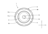
- FIG. 1 is a front view of a motor-operated valve according to a first embodiment of the present invention
- FIG. FIG. FIG. 2 is a cross-sectional view taken along line IV-IV in FIG. 5 is a cross-sectional view taken along line VV in FIG. 4.
- FIG. 2 is a cross-sectional view of a valve body assembly of the motor-operated valve.
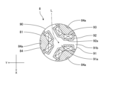
- FIG. 2 is a front view of a stator unit of the motor-operated valve.
- FIG. 4 is a rear view of the stator unit.
- FIG. 4 is a bottom view of the stator unit.
- 8 is a cross-sectional view taken along line XX in FIG. 7.
- 11 is a cross-sectional view taken along line XI-XI of FIG. FIG.
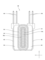
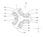
- FIG. 4 is a rear view of the stator of the stator unit.
- FIG. FIG. 13 is a cross-sectional view taken along line XV-XV in FIG. 12.
- 16 is a cross-sectional view taken along line XVI-XVI in FIG. 15.
- 16 is a cross-sectional view taken along line XVII-XVII in FIG. 15.
- FIG. 5 is a cross-sectional view of a valve device according to a second embodiment of the present invention.
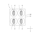
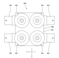
- FIG. 10 is a plan view of a valve device according to a third embodiment of the present invention.
- FIG. 1 is a plan view of a conventional valve device.
- the motor-operated valve according to the first embodiment of the present invention will be described below with reference to Figs. 1 to 17.
- the motor-operated valve according to this embodiment is used, for example, to control the flow rate of refrigerant in an automotive air conditioner.
- FIG. 1 is a front view, a plan view and a bottom view of an electric valve according to a first embodiment of the present invention.
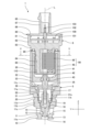
- FIG. 4 is a cross-sectional view taken along line IV-IV in FIG. 1.
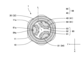
- FIG. 5 is a cross-sectional view taken along line V-V in FIG. 4.
- FIG. 6 is a cross-sectional view of a valve body assembly of an electric valve.
- FIG. 7, 8 and 9 are a front view, a rear view and a bottom view of a stator unit of an electric valve.
- FIG. 10 is a cross-sectional view taken along line X-X in FIG. 7.
- FIG. 11 is a cross-sectional view taken along line XI-XI in FIG. 10.
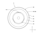
- FIG. 12 is a rear view, a plan view and a bottom view of a stator of a stator unit.
- FIG. 15 is a cross-sectional view taken along line XV-XV in FIG. 12.
- FIG. 16 is a cross-sectional view taken along line XVI-XVI in FIG. 15.
- FIG. 17 is a cross-sectional view taken along line XVII-XVII in FIG. 15.
- the X direction indicated by the arrow X is the left-right direction
- the Y direction indicated by the arrow Y is the front-back direction
- the Z direction indicated by the arrow Z is the up-down direction (axis L direction).
- the arrow X with the letter "X" is the right direction
- the arrow Y with the letter "Y” is the front direction
- the arrow Z with the letter "Z” is the upward direction.
- the motor-operated valve 1 of the first embodiment has a valve body assembly 5 and a stator unit 8.
- the valve body assembly 5 includes a valve body 10, a valve body 20, a rotor case 30, a bearing 35, a rotor 40, a drive shaft 50, and an inner case 60.
- the valve body 10 has a body member 11, a sleeve 18, and a valve body support plate 19.
- the main body member 11 is made of a metal such as an aluminum alloy.
- the cross-sectional outline of the upper portion 11a of the main body member 11 is hexagonal.
- the "cross-sectional outline" is a cross section perpendicular to the axis L.
- the main body member 11 has a valve chamber 12, a valve port 13, a valve seat 14, a first connecting passage 15, a second connecting passage 16, and a mounting hole 17.
- the valve orifice 13 is connected to the valve chamber 12.
- the valve orifice 13 is surrounded by a valve seat 14 in the valve chamber 12.
- the first connecting passage 15 extends from the valve chamber 12 in the left-right direction and the front-rear direction.
- the second connecting passage 16 extends downward from the valve orifice 13.
- the mounting hole 17 is disposed on the upper surface 11c of the main body member 11.
- the mounting hole 17 is connected to the valve chamber 12.
- the main body member 11 has a retaining surface 17a, which is an annular flat surface facing upward.
- the retaining surface 17a is disposed at the connection point between the mounting hole 17 and the valve chamber 12.
- the main body member 11 has a male thread 11s and a female thread 11t.
- the male thread 11s is disposed on the outer peripheral surface of the lower part 11b of the main body member 11.
- the female thread 11t is disposed on the inner peripheral surface of the mounting hole 17.
- the main body member 11 also has annular grooves 11d and 11e.
- the annular groove 11d is disposed at a location above the male thread 11s on the outer peripheral surface of the lower part 11b of the main body member 11.
- the annular groove 11e is disposed at a location below the first connection passage 15 on the outer peripheral surface of the lower part 11b of the main body member 11.
- O-rings are disposed in the annular grooves 11d and 11e.
- the sleeve 18 is made of synthetic resin or metal.
- the sleeve 18 has an overall cylindrical shape.
- the sleeve 18 integrally has a small diameter portion 18a, a large diameter portion 18b, and a flange portion 18c.
- the small diameter portion 18a and the large diameter portion 18b have a cylindrical shape.
- the inner diameter of the large diameter portion 18b is larger than the outer diameter of the small diameter portion 18a.
- the lower end of the large diameter portion 18b is coaxially connected to the upper end of the small diameter portion 18a.
- the flange portion 18c has an annular plate shape.
- the inner peripheral edge of the flange portion 18c is connected to the upper end of the large diameter portion 18b.
- the small diameter portion 18a and the large diameter portion 18b are disposed in the valve chamber 12.
- the flange portion 18c is in contact with the retaining surface 17a of the main body member 11.
- the valve body support plate 19 is made of synthetic resin or metal.
- the valve body support plate 19 has a circular plate shape.
- the outer peripheral edge of the valve body support plate 19 is circular and the inner peripheral edge is square.
- the valve body support plate 19 is placed in the mounting hole 17, and the lower surface of the valve body support plate 19 contacts the flange portion 18c of the sleeve 18.
- the valve body 20 is made of synthetic resin or metal.
- the valve body 20 integrally has a shaft portion 21 and a valve portion 22.
- the shaft portion 21 has an overall columnar shape.
- the upper portion 21a of the shaft portion 21 has a rectangular columnar shape.
- the outer shape of the cross section of the upper portion 21a is the same square as the inner peripheral edge of the valve body support plate 19.
- the lower portion 21b of the shaft portion 21 has a cylindrical shape.
- the outer diameter of the lower portion 21b is the same as the inner diameter of the small diameter portion 18a of the sleeve 18.
- the shaft portion 21 has a threaded hole 21c and a female thread 21t.
- the threaded hole 21c is located on the upper end surface of the shaft portion 21.
- the female thread 21t is located on the inner peripheral surface of the threaded hole 21c.
- the upper part 21a of the shaft part 21 is disposed inside the valve body support plate 19.
- the lower part 21b of the shaft part 21 is disposed inside the small diameter part 18a of the sleeve 18.
- the valve body 20 is supported by the sleeve 18 and the valve body support plate 19 so that it can move up and down (in the direction of the axis L).
- the valve body 20 is restricted from rotating about the axis L by the valve body support plate 19.
- the shape of the upper part 21a of the shaft part 21 and the shape of the inner peripheral edge of the valve body support plate 19 may be any shape that restricts the rotation of the valve body 20 about the axis L.
- the valve portion 22 has a truncated cone shape with a diameter that decreases from top to bottom.
- the valve portion 22 is coaxially connected to the lower end of the shaft portion 21.
- the valve portion 22 is disposed in the valve chamber 12 and the valve orifice 13.
- the valve portion 22 faces the valve orifice 13 and the valve seat 14 in the vertical direction. When the valve portion 22 comes into contact with the valve seat 14, the valve orifice 13 closes. When the valve portion 22 moves away from the valve seat 14, the valve orifice 13 opens, and a throttle flow path is formed between the valve portion 22 and the valve orifice 13.
- the rotor case 30 is made of a metal such as non-magnetic stainless steel.
- non-magnetic refers to the property of not being magnetized even when placed in a magnetic field (including the property of not being substantially magnetized).
- the rotor case 30 may be made of a synthetic resin.
- the rotor case 30 has an overall cylindrical shape.
- the rotor case 30 integrally has a first portion 31, a second portion 32, and a connecting portion 33.
- the first part 31 has a cylindrical shape.
- the first part 31 has a male thread 31s.
- the male thread 31s is disposed on the lower part of the outer circumferential surface of the first part 31.
- the first part 31 is disposed in the mounting hole 17 of the main body member 11, and the male thread 31s of the first part 31 is screwed into the female thread 11t of the main body member 11.
- the first part 31 i.e., the rotor case 30
- the flange portion 18c of the sleeve 18 and the valve body support plate 19 are held between the lower end of the first part 31 and the holding surface 17a of the main body member 11.
- the first part 31 has a bearing installation surface 31a, which is an annular flat surface facing upward.
- the bearing installation surface 31a is disposed on the inner circumferential surface of the first part 31.
- the second part 32 has a cylindrical shape.
- the inner diameter of the second part 32 is larger than the outer diameter of the first part 31.
- the connection part 33 has a circular plate shape.
- the inner peripheral edge of the connection part 33 is connected to the upper end of the first part 31, and the outer peripheral edge of the connection part 33 is connected to the lower end of the second part 32.
- the bearing 35 is, for example, a radial ball bearing.
- the bearing 35 is disposed inside the first portion 31.
- the lower end of the outer ring of the bearing 35 contacts the bearing mounting surface 31a.
- the bearing 35 may be a thrust ball bearing.
- the rotor 40 has an overall cylindrical shape.
- the rotor 40 is disposed inside the second part 32 of the rotor case 30.
- the rotor 40 integrally has a cylindrical portion 41, a disk portion 42, and a connecting portion 43.
- the cylindrical portion 41 has multiple north poles and multiple south poles.
- the multiple north poles and multiple south poles are alternately arranged at equal angular intervals in the circumferential direction on the inner surface of the cylindrical portion 41.
- the multiple north poles and multiple south poles extend in the vertical direction.
- the cylindrical portion 41 has, for example, five north poles and five south poles.
- the disc portion 42 is connected to the lower end of the cylindrical portion 41.
- the connecting portion 43 has a cylindrical shape.
- the connecting portion 43 is arranged coaxially in the center of the disc portion 42.
- the rotor 40 is a magnet rotor.
- the drive shaft 50 is made of synthetic resin or metal.
- the drive shaft 50 has an overall cylindrical shape.
- the drive shaft 50 has a male thread 51s.
- the male thread 51s is disposed on the outer peripheral surface of the lower part of the drive shaft 50.
- the male thread 51s is screwed into the female thread 21t of the valve body 20.
- the drive shaft 50 may have a female thread and the valve body 20 may have a male thread.
- the female thread 21t and the male thread 51s are a feed screw mechanism that moves the valve body 20 in the vertical direction.
- the center part of the drive shaft 50 is rotatably supported by the bearing 35.
- the drive shaft 50 has a support surface 50a, which is an annular flat surface facing downward.
- the upper end of the inner ring of the bearing 35 is in contact with the support surface 50a.
- the upper part of the drive shaft 50 is fitted into the connecting part 43.
- the drive shaft 50 rotates together with the rotor 40.
- the inner case 60 is made of a metal such as non-magnetic stainless steel.
- the inner case 60 may be made of a synthetic resin.
- the inner case 60 integrally has a peripheral wall portion 61, a bottom wall portion 62, and an annular portion 63.
- the peripheral wall portion 61 has a cylindrical shape.
- the peripheral wall portion 61 has a plurality of protrusions 61a.
- the plurality of protrusions 61a are arranged on the upper part of the inner peripheral surface of the peripheral wall portion 61.
- the bottom wall portion 62 has a disk shape.
- the outer peripheral edge of the bottom wall portion 62 is connected to the lower end (first end) of the peripheral wall portion 61.
- the annular portion 63 has a circular ring plate shape.
- the inner peripheral edge of the annular portion 63 is connected to the upper end (second end) of the peripheral wall portion 61.
- the outer peripheral edge of the annular portion 63 is joined to the upper end (one end) of the second part 32 of the rotor case 30 around the entire circumference.
- the peripheral wall portion 61 and the bottom wall portion 62 are arranged inside the rotor 40.
- the second part 32 of the rotor case 30 and the inner case 60 form a rotor space 65.
- the rotor 40 is arranged in the rotor space 65.
- the rotor space 65 is sealed from the outside of the motor-operated valve 1.
- the rotor space 65 is connected to the valve chamber 12 through a gap. The refrigerant in the valve chamber 12 is introduced into the rotor space 65.
- the stator unit 8 has a housing 80, a stator 90, a control device 100, and a magnetic sensor 110.
- the housing 80 is made of synthetic resin.
- the housing 80 has a housing body 81 and a lid body 85.
- the housing body 81 has a peripheral wall portion 82, a bottom wall portion 83, and a support portion 84, which are integral with the housing body 81.
- the peripheral wall portion 82 has a cylindrical shape.
- the bottom wall portion 83 has a disk shape.
- the bottom wall portion 83 is connected to the lower end of the peripheral wall portion 82.
- the support portion 84 has a cylindrical shape.
- the support portion 84 is coaxially connected to the lower surface of the bottom wall portion 83.
- the outer diameter of the support portion 84 is the same as the inner diameter of the peripheral wall portion 61 of the inner case 60.
- the support portion 84 has a plurality of recesses 84a.
- the plurality of recesses 84a are arranged on the upper part of the outer circumferential surface of the support portion 84.
- the support portion 84 is arranged in the inner case 60, and the plurality of protrusions 61a of the inner case 60 are fitted into the plurality of recesses 84a.
- the support portion 84 is fitted into the inner case 60.
- the gap between the bottom wall portion 83 and the annular portion 63 of the inner case 60 is sealed with an O-ring 89.
- the lid body 85 has an integral lid portion 86 and a connector portion 87.
- the lid portion 86 has a disk shape.
- the outer peripheral edge of the lid portion 86 is joined to the upper end of the peripheral wall portion 82.
- the connector portion 87 has an elongated cylindrical shape.
- the connector portion 87 extends upward from the center of the upper surface of the lid portion 86.
- the peripheral wall portion 82, the bottom wall portion 83, and the lid portion 86 form a control device space 88.
- the stator 90 has a laminated core 91, a bobbin 92, multiple coils 93, and multiple coil terminals 94.
- the laminated core 91 has a central portion 91a and a plurality of pole portions 91b, which are integral with each other.
- the central portion 91a has a cylindrical shape.
- the central portion 91a is arranged coaxially with the rotor 40.
- the plurality of pole portions 91b extend radially (perpendicular to the axis L) from the central portion 91a.
- the plurality of pole portions 91b are arranged at equal angular intervals in the circumferential direction on the outer circumferential surface of the central portion 91a.
- the laminated core 91 has, for example, three pole portions 91b.
- the laminated core 91 is formed by stacking a plurality of thin electromagnetic steel sheets. An insulating film is formed on the surface of the electromagnetic steel sheets. The electromagnetic steel sheets are arranged along the extension direction of the plurality of pole portions 91b.
- the bobbin 92 is made of synthetic resin.
- the bobbin 92 has multiple sleeves 92a that cover multiple poles 91b.
- the poles 91b are arranged inside the sleeves 92a.
- the poles 91b pass through the sleeves 92a.
- the multiple coils 93 are wires wound around the multiple sleeves 92a of the bobbin 92.
- the multiple coils 93 are arranged on the multiple poles 91b.
- the multiple coil terminals 94 extend upward from the bobbin 92.
- the multiple coil terminals 94 are electrically connected to the multiple coils 93.
- the stator 90 is embedded in the support portion 84 of the housing 80.
- the stator 90 is disposed inside the peripheral wall portion 61 of the inner case 60 together with the support portion 84 of the housing 80.
- the rotor 40 is disposed outside the peripheral wall portion 61.
- the rotor 40 and the stator 90 constitute a stepping motor 98.
- the motor-operated valve 1 may have other types of motors, such as a brushless DC motor.
- the control device 100 is disposed in the control device space 88.
- the control device 100 has a board 101, terminal components 102, and a computer (not shown).
- the board 101 is a printed circuit board on which electronic components including a computer are mounted.
- a plurality of coil terminals 94 of the stator 90 are connected to the board 101.
- the terminal components 102 have a plurality of connector terminals 103.
- One end of the plurality of connector terminals 103 is connected to the board 101, and the other end is disposed inside the connector portion 87.
- the computer is responsible for controlling the motor-operated valve 1.
- the magnetic sensor 110 is a sensor having a Hall element that outputs a signal (digital signal) according to the direction of the magnetic field.
- the magnetic sensor 110 is disposed at the bottom of the support portion 84 of the housing 80.
- the magnetic sensor 110 is disposed between adjacent pole portions 91b on the support portion 84.
- the magnetic sensor 110 faces radially the magnetic poles (north pole and south pole) of the rotor 40 via the peripheral wall portion 61 of the inner case 60.
- the magnetic sensor 110 detects the magnetism of the rotor 40.
- the magnetic sensor 110 is electrically connected to the substrate 101, and the computer detects the rotational position of the rotor 40 based on the signal from the magnetic sensor 110.
- the main body member 11 (valve chamber 12, valve port 13, valve seat 14, mounting hole 17), sleeve 18, valve body support plate 19, valve body 20, rotor case 30, bearing 35, rotor 40, drive shaft 50, inner case 60, housing main body 81, lid body 85 (lid portion 86, connector portion 87), and stator 90 each have a central axis that coincides with the axis L.
- the motor-operated valve 1 current is supplied to the multiple coils 93 of the stator 90 to rotate the rotor 40 in a first direction.
- the drive shaft 50 rotates together with the rotor 40. Due to the feed screw action between the male thread 51s of the drive shaft 50 and the female thread 21t of the valve body 20, the valve body 20 moves downward, reducing the opening area of the valve orifice 13 (throttling flow passage). When the valve body 20 contacts the valve seat 14 and closes the valve orifice 13, the motor-operated valve 1 is fully closed.
- the motor-operated valve 1 In the motor-operated valve 1, current is supplied to the multiple coils 93 of the stator 90 to rotate the rotor 40 in the second direction.
- the drive shaft 50 rotates together with the rotor 40. Due to the feed screw action between the male thread 51s of the drive shaft 50 and the female thread 21t of the valve body 20, the valve body 20 moves upward, increasing the opening area of the valve orifice 13.
- the motor-operated valve 1 is in a fully open state.
- the opening area of the valve orifice 13 is at its maximum.
- the sleeve 18 and valve body support plate 19 are placed in the mounting hole 17 of the main body member 11.
- the rotor case 30 (first part 31) is inserted into the mounting hole 17 of the main body member 11 while rotating, and the rotor case 30 is attached to the main body member 11.
- the sleeve 18 and valve body support plate 19 are held by the main body member 11 and the rotor case 30.
- the valve body 20 is inserted into the valve body support plate 19 and sleeve 18.
- the bearing 35 is fitted into the first part 31 of the rotor case 30.
- the upper part of the drive shaft 50 is fitted into the connecting part 43 of the rotor 40.
- the drive shaft 50 is inserted into the bearing 35, and the male thread 51s of the drive shaft 50 is screwed into the female thread 21t of the valve body 20.
- the centre of the drive shaft 50 is fitted into the bearing 35.
- the peripheral wall portion 61 and bottom wall portion 62 of the inner case 60 are inserted into the rotor 40, and the annular portion 63 of the inner case 60 is welded to the upper end of the rotor case 30 (second portion 32). This completes the valve body assembly 5.
- the laminated core 91 is placed in a molding die for the stator, and the bobbin 92 is injection molded integrally with the laminated core 91. Then, wire is wound around the multiple sleeve portions 92a of the bobbin 92, and multiple coils 93 are formed on the pole portions 91b of the laminated core 91. This completes the stator 90.
- the stator 90 is placed in a molding die for the housing body, and the housing body 81 is injection molded integrally with the stator 90.
- the magnetic sensor 110 is attached to the support portion 84 of the housing body 81. Wiring (not shown) that electrically connects the magnetic sensor 110 to the substrate 101 is embedded in the housing body 81.
- the lid body 85 is injection molded using a molding die for the lid.
- the control device 100 is placed inside the peripheral wall portion 82 of the housing body 81, and the outer periphery of the lid portion 86 of the lid body 85 is ultrasonically welded (or infrared ray welded) to the upper end of the peripheral wall portion 82. This completes the stator unit 8.
- the support part 84 of the stator unit 8 is inserted into the inner case 60 of the valve body assembly 5, and the support part 84 is fitted into the inner case 60.
- the multiple protrusions 61a of the inner case 60 fit into the multiple recesses 84a of the support part 84, and the stator unit 8 is fixed to the valve body assembly 5. This completes the motor-operated valve 1.
- the motor-operated valve 1 has a cylindrical rotor case 30, a cylindrical rotor 40 arranged inside the rotor case 30, a valve body 20 that moves in response to the rotation of the rotor 40, and a stator 90 arranged inside the rotor 40 and constituting a stepping motor 98 together with the rotor 40.
- the outer diameter of the motor-operated valve 1 is smaller than in a configuration in which the stator is arranged outside the rotor. Therefore, the motor-operated valve 1 can be arranged in a relatively small space.
- the motor-operated valve 1 also has an inner case 60.
- the inner case 60 integrally has a cylindrical peripheral wall portion 61, a disk-shaped bottom wall portion 62 connected to the lower end of the peripheral wall portion 61, and an annular portion 63 whose inner peripheral edge is connected to the upper end of the peripheral wall portion 61.
- the outer peripheral edge of the annular portion 63 is joined to the upper end of the rotor case 30.
- the peripheral wall portion 61 and the bottom wall portion 62 are disposed inside the rotor 40.
- the stator 90 is disposed inside the peripheral wall portion 61. In this manner, the rotor case 30 and the inner case 60 form a rotor space 65 in which the rotor 40 is disposed. A refrigerant is introduced into the rotor space 65.
- the rotor space 65 is sealed from the space inside the peripheral wall portion 61 in which the stator 90 is disposed. Therefore, the space in which the stator 90 is disposed can be partitioned from the rotor space 65
- the motor-operated valve 1 also has a housing 80 made of synthetic resin.
- the housing 80 has a cylindrical support portion 84 in which the stator 90 is embedded.
- the support portion 84 is fitted into the inner case 60. In this manner, the stator 90 can be protected by the support portion 84. Furthermore, by fitting the support portion 84 into the inner case 60, the stator 90 can be appropriately positioned inside the inner case 60.
- the housing 80 also has a connector portion 87 that is shaped like an elongated cylinder.
- the connector portion 87 extends in the axial direction (axis L direction) of the rotor 40. This makes it possible to reduce the installation area of the motor-operated valve 1 (area when viewed from the axis L direction).
- the stator 90 is arranged coaxially with the rotor 40 and has a laminated core 91 having a plurality of pole portions 91b extending radially, and a plurality of coils 93 arranged on the plurality of pole portions 91b.
- the electromagnetic steel sheets of the laminated core 91 are arranged along the extension direction of the plurality of pole portions 91b (direction perpendicular to the axis L). In the laminated core 91, magnetic flux passes in the extension direction of the plurality of pole portions 91b, and the current flowing between the electromagnetic steel sheets is limited. This allows the iron loss in the laminated core 91 to be reduced.
- the motor-operated valve 1 also has a magnetic sensor 110 that detects the magnetism of the rotor 40.
- the magnetic sensor 110 is disposed between the pole parts 91b on the support part 84 ( Figure 7). In this manner, the magnetic sensor 110 is disposed close to the rotor 40 and faces the rotor 40 in the radial direction.
- the motor-operated valve 1 also has a drive shaft 50 that rotates together with the rotor 40.
- the valve body 20 has a female thread 21t.
- the drive shaft 50 has a male thread 51s that is screwed into the female thread 21t.
- the female thread 21t and the male thread 51s form a feed screw mechanism that moves the valve body 20. In this way, the valve body 20 can be moved with a relatively simple configuration.
- valve device according to the second embodiment of the present invention will be described with reference to FIG. 18.
- valve device 2 of the second embodiment has the motor-operated valve 1 of the first embodiment and a flow path block 150.
- the flow path block 150 has a rectangular parallelepiped shape.
- the flow path block 150 is made of a metal, for example, an aluminum alloy.
- the upper surface of the flow path block 150 is a mounting surface 151 on which the motor-operated valve 1 is disposed.
- the flow passage block 150 has a first passage 155, a second passage 156, and a mounting hole 157.
- the mounting hole 157 is disposed in the mounting surface 151.
- the first passage 155 extends forward from the mounting hole 157.
- the second passage 156 extends downward from the mounting hole 157.
- the flow passage block 150 has a female thread 150t.
- the female thread 150t is arranged on the inner circumferential surface of the mounting hole 157.
- the lower part 11b of the main body member 11 of the electric valve 1 is arranged in the mounting hole 157, and the male thread 11s of the main body member 11 is screwed into the female thread 150t of the flow passage block 150.
- the electric valve 1 is attached to the flow passage block 150 by a screw structure, with a jig attached to the hexagonal upper part 11a of the main body member 11 and rotating it around the axis L.
- the space between the main body member 11 and the flow passage block 150 is sealed by O-rings 158 and 159 arranged in the annular grooves 11d and 11e.
- the connector part 87 of the electric valve 1 faces upward.
- the first passage 155 is connected to the valve chamber 12 of the electric valve 1 via the mounting hole 157 and the first connection passage 15.
- the second passage 156 is connected to the valve port 13 of the motor-operated valve 1 via the second connection passage 16.
- the valve device 2 may have a configuration in which the main body member 11 of the motor-operated valve 1 is omitted and the rotor case 30 is directly attached to the flow path block 150.
- the flow path block 150 has the same (including substantially the same) valve chamber, valve port, valve seat, and mounting hole as those of the motor-operated valve 1.
- valve device according to the third embodiment of the present invention will be described with reference to FIG. 19.
- the valve device 3 of the second embodiment has a plurality of motor-operated valves 1 of the first embodiment and a flow path block 250.
- the flow path block 250 has a rectangular parallelepiped shape.
- the flow path block 250 is made of a metal, for example, an aluminum alloy.
- the upper surface of the flow path block 250 is a mounting surface 251 on which multiple motor-operated valves 1 are arranged.
- the flow passage block 250 has multiple mounting holes (not shown).
- the multiple mounting holes are arranged on the mounting surface 251.
- Multiple female threads are arranged on the inner surfaces of the multiple mounting holes.
- the lower parts 11b of the main body members 11 of the multiple motor-operated valves 1 are arranged in the multiple mounting holes, and the male threads 11s of the main body member 11 are screwed into the female threads of the flow passage block 250.
- the connector parts 87 of the multiple motor-operated valves 1 face upward.
- Valve devices 2 and 3 have the same effect as motor-operated valve 1.
- valve device 3 the installation area of each of the multiple motor-operated valves 1 is small, so the flow path block 250 can be made small. Furthermore, in the valve device 3, the connector parts 87 of each of the multiple motor-operated valves 1 face the same direction (upward). Therefore, in a system in which the valve device 3 is incorporated, it is only necessary to provide space above the valve device 3 for arranging the cables connected to the connector parts 87 of the multiple motor-operated valves 1, and the valve device 3 can be arranged in a relatively small space.
- cylinder cylindrical
- column cylindrical
- rectangular prism a member that has substantially the shape of the term.
- a “cylindrical member” includes both cylindrical members and substantially cylindrical members.
Landscapes
- Engineering & Computer Science (AREA)
- General Engineering & Computer Science (AREA)
- Mechanical Engineering (AREA)
- Physics & Mathematics (AREA)
- Electromagnetism (AREA)
- Power Engineering (AREA)
- Electrically Driven Valve-Operating Means (AREA)
- Connection Of Motors, Electrical Generators, Mechanical Devices, And The Like (AREA)
Abstract
Description
Claims (8)
- 筒形状のローターケースと、
前記ローターケースの内側に配置される円筒形状のマグネットローターと、
前記マグネットローターの回転に応じて移動する弁体と、
前記マグネットローターの内側に配置され、前記マグネットローターとともにモーターを構成するステーターと、を有することを特徴とする電動弁。 - 前記電動弁が、円筒形状の周壁部と、前記周壁部の第1端に接続された円板形状の底壁部と、前記周壁部の第2端に内周縁が接続された環状部と、を一体的に有する内ケースをさらに有し、
前記環状部の外周縁が、前記ローターケースの一端に接合され、
前記周壁部および前記底壁部が、前記マグネットローターの内側に配置され、
前記周壁部の内側に、前記ステーターが配置される、請求項1に記載の電動弁。 - 前記電動弁が、合成樹脂製のハウジングをさらに有し、
前記ハウジングが、前記ステーターが埋め込まれる円柱形状の支持部を有し、
前記支持部が、前記内ケースに嵌合されている、請求項2に記載の電動弁。 - 前記ハウジングが、筒形状のコネクタ部をさらに有し、
前記コネクタ部が、前記マグネットローターの軸方向に延びている、請求項3に記載の電動弁。 - 前記ステーターが、前記マグネットローターと同軸に配置され、径方向に延びる複数の極部を有する積層コアと、前記極部に配置された複数のコイルと、を有する、請求項4に記載の電動弁。
- 前記電動弁が、前記マグネットローターの磁気を検出する磁気センサーをさらに有し、
前記磁気センサーが、前記支持部における前記極部と前記極部との間の箇所に配置される、請求項5に記載の電動弁。 - 前記電動弁が、前記マグネットローターとともに回転する駆動軸をさらに有し、
前記弁体が雌ねじを有しかつ前記駆動軸が前記雌ねじに螺合される雄ねじを有し、または、前記駆動軸が雌ねじを有しかつ前記弁体が前記雌ねじに螺合される雄ねじを有し、
前記雌ねじおよび前記雄ねじが、前記弁体を移動させる送りねじ機構を構成する、請求項1に記載の電動弁。 - 少なくとも1つの電動弁と、前記電動弁が配置される取付面を有する流路ブロックと、を有する弁装置であって、
前記電動弁が、
筒形状のローターケースと、
前記ローターケースの内側に配置される円筒形状のマグネットローターと、
前記マグネットローターの回転に応じて移動する弁体と、
前記マグネットローターの内側に配置され、前記マグネットローターとともにモーターを構成するステーターと、を有することを特徴とする弁装置。
Priority Applications (3)
| Application Number | Priority Date | Filing Date | Title |
|---|---|---|---|
| KR1020247030786A KR20240176817A (ko) | 2023-06-15 | 2024-03-08 | 전동밸브 및 밸브장치 |
| EP24823041.9A EP4729816A1 (en) | 2023-06-15 | 2024-03-08 | Electric valve and valve device |
| CN202480001686.8A CN121311704A (zh) | 2023-06-15 | 2024-03-08 | 电动阀及阀装置 |
Applications Claiming Priority (2)
| Application Number | Priority Date | Filing Date | Title |
|---|---|---|---|
| JP2023-098626 | 2023-06-15 | ||
| JP2023098626A JP7607970B1 (ja) | 2023-06-15 | 2023-06-15 | 電動弁および弁装置 |
Publications (1)
| Publication Number | Publication Date |
|---|---|
| WO2024257418A1 true WO2024257418A1 (ja) | 2024-12-19 |
Family
ID=93851804
Family Applications (1)
| Application Number | Title | Priority Date | Filing Date |
|---|---|---|---|
| PCT/JP2024/008939 Ceased WO2024257418A1 (ja) | 2023-06-15 | 2024-03-08 | 電動弁および弁装置 |
Country Status (5)
| Country | Link |
|---|---|
| EP (1) | EP4729816A1 (ja) |
| JP (2) | JP7607970B1 (ja) |
| KR (1) | KR20240176817A (ja) |
| CN (1) | CN121311704A (ja) |
| WO (1) | WO2024257418A1 (ja) |
Citations (5)
| Publication number | Priority date | Publication date | Assignee | Title |
|---|---|---|---|---|
| JPS60260781A (ja) * | 1984-06-08 | 1985-12-23 | Fuji Koki Seisakusho:Kk | 電動流量制御弁 |
| EP0937928A1 (en) * | 1998-02-23 | 1999-08-25 | ERRENNEGI S.r.l. | Electric motor-operated flow control valve |
| JP2015045411A (ja) * | 2011-12-07 | 2015-03-12 | 株式会社鷺宮製作所 | インサート成形方法によって製造された雌ネジ部材を備えた電動弁、および、雌ネジ部材、ならびに、ネジブッシュ |
| JP2015201929A (ja) * | 2014-04-04 | 2015-11-12 | 日本精工株式会社 | モータ、搬送装置及び半導体製造装置 |
| JP2022083453A (ja) | 2020-11-24 | 2022-06-03 | 株式会社不二工機 | 電動弁およびその組立方法 |
Family Cites Families (6)
| Publication number | Priority date | Publication date | Assignee | Title |
|---|---|---|---|---|
| US5011112A (en) | 1988-12-20 | 1991-04-30 | American Standard Inc. | Incremental electrically actuated valve |
| JPH0511783U (ja) * | 1991-07-19 | 1993-02-12 | 富士電気化学株式会社 | アウターロータ形ステツピングモータのステータ構造 |
| JP2001304167A (ja) * | 2000-04-27 | 2001-10-31 | Aisan Ind Co Ltd | 磁気結合ポンプ |
| DE102016203560B4 (de) * | 2016-03-04 | 2025-10-16 | Schaeffler Technologies AG & Co. KG | Aktoranordnung mit einem Sensormodul für einen Aktor mit verschiebbarem Anker |
| JP7462282B2 (ja) * | 2019-08-22 | 2024-04-05 | 株式会社テージーケー | 電動弁 |
| JP2022068406A (ja) * | 2020-10-22 | 2022-05-10 | 愛三工業株式会社 | 流体制御弁及びegrユニット |
-
2023
- 2023-06-15 JP JP2023098626A patent/JP7607970B1/ja active Active
-
2024
- 2024-03-08 EP EP24823041.9A patent/EP4729816A1/en active Pending
- 2024-03-08 WO PCT/JP2024/008939 patent/WO2024257418A1/ja not_active Ceased
- 2024-03-08 CN CN202480001686.8A patent/CN121311704A/zh active Pending
- 2024-03-08 KR KR1020247030786A patent/KR20240176817A/ko active Pending
- 2024-12-05 JP JP2024211959A patent/JP7834381B2/ja active Active
Patent Citations (5)
| Publication number | Priority date | Publication date | Assignee | Title |
|---|---|---|---|---|
| JPS60260781A (ja) * | 1984-06-08 | 1985-12-23 | Fuji Koki Seisakusho:Kk | 電動流量制御弁 |
| EP0937928A1 (en) * | 1998-02-23 | 1999-08-25 | ERRENNEGI S.r.l. | Electric motor-operated flow control valve |
| JP2015045411A (ja) * | 2011-12-07 | 2015-03-12 | 株式会社鷺宮製作所 | インサート成形方法によって製造された雌ネジ部材を備えた電動弁、および、雌ネジ部材、ならびに、ネジブッシュ |
| JP2015201929A (ja) * | 2014-04-04 | 2015-11-12 | 日本精工株式会社 | モータ、搬送装置及び半導体製造装置 |
| JP2022083453A (ja) | 2020-11-24 | 2022-06-03 | 株式会社不二工機 | 電動弁およびその組立方法 |
Non-Patent Citations (1)
| Title |
|---|
| See also references of EP4729816A1 |
Also Published As
| Publication number | Publication date |
|---|---|
| JP2025003917A (ja) | 2025-01-14 |
| JP2025026533A (ja) | 2025-02-21 |
| JP7834381B2 (ja) | 2026-03-24 |
| EP4729816A1 (en) | 2026-04-22 |
| CN121311704A (zh) | 2026-01-09 |
| JP7607970B1 (ja) | 2025-01-06 |
| KR20240176817A (ko) | 2024-12-24 |
Similar Documents
| Publication | Publication Date | Title |
|---|---|---|
| US7508102B2 (en) | Brushless motor having a circuit board having a central hole and escape holes | |
| US5521451A (en) | Low-cost stepping or synchronous motor | |
| JP6087123B2 (ja) | ブラシレスモータ | |
| JP2006174526A (ja) | モータ | |
| US20190149014A1 (en) | Motor | |
| EP3806294A1 (en) | Motor device | |
| EP3474425B1 (en) | Motor device | |
| JP3715519B2 (ja) | 回転電機および回転電機の製造方法 | |
| JP7607970B1 (ja) | 電動弁および弁装置 | |
| EP1372241A2 (en) | Multi-pole electromagnetic motor apparatus and method of assembling | |
| US5463314A (en) | Gauge with magnetically fixed rest position | |
| JP2025003651A (ja) | ステーターユニット、電動弁および電動弁装置 | |
| JP2007143255A (ja) | 平滑電機子巻線形モータおよびブレーキ付モータ | |
| JP2025155425A (ja) | 電動弁および弁装置 | |
| WO2020166344A1 (ja) | モータ装置 | |
| JP2026014121A (ja) | 電動弁 | |
| WO2025210991A1 (ja) | 電動弁および弁装置、ならびにステーターユニットの製造方法 | |
| JPH05199724A (ja) | 電動機 | |
| WO2018193616A1 (ja) | Dcモータ、egrバルブ、vgアクチュエータ、およびウエストゲートアクチュエータ | |
| US4479068A (en) | Stepping motor device for changing the position of a rotating body | |
| JPH06245455A (ja) | 偏平型直流モータ | |
| JP2025135983A (ja) | モータ | |
| JP2025018077A (ja) | アクチュエータ装置 | |
| JP2002130522A (ja) | 電磁流量制御弁 | |
| CN114744786A (zh) | 一种有限转角的轴向磁场电机 |
Legal Events
| Date | Code | Title | Description |
|---|---|---|---|
| 121 | Ep: the epo has been informed by wipo that ep was designated in this application |
Ref document number: 24823041 Country of ref document: EP Kind code of ref document: A1 |
|
| WWE | Wipo information: entry into national phase |
Ref document number: 2024823041 Country of ref document: EP |
|
| NENP | Non-entry into the national phase |
Ref country code: DE |
|
| ENP | Entry into the national phase |
Ref document number: 2024823041 Country of ref document: EP Effective date: 20260115 |
|
| ENP | Entry into the national phase |
Ref document number: 2024823041 Country of ref document: EP Effective date: 20260115 |
|
| ENP | Entry into the national phase |
Ref document number: 2024823041 Country of ref document: EP Effective date: 20260115 |
|
| ENP | Entry into the national phase |
Ref document number: 2024823041 Country of ref document: EP Effective date: 20260115 |
|
| WWP | Wipo information: published in national office |
Ref document number: 2024823041 Country of ref document: EP |