WO2024257280A1 - シェアリングアクセスポイント、シェアードアクセスポイント及び端末 - Google Patents
シェアリングアクセスポイント、シェアードアクセスポイント及び端末 Download PDFInfo
- Publication number
- WO2024257280A1 WO2024257280A1 PCT/JP2023/022136 JP2023022136W WO2024257280A1 WO 2024257280 A1 WO2024257280 A1 WO 2024257280A1 JP 2023022136 W JP2023022136 W JP 2023022136W WO 2024257280 A1 WO2024257280 A1 WO 2024257280A1
- Authority
- WO
- WIPO (PCT)
- Prior art keywords
- terminal
- shared
- common connection
- terminals
- sharing
- Prior art date
- Legal status (The legal status is an assumption and is not a legal conclusion. Google has not performed a legal analysis and makes no representation as to the accuracy of the status listed.)
- Ceased
Links
Images




Classifications
-
- H—ELECTRICITY
- H04—ELECTRIC COMMUNICATION TECHNIQUE
- H04W—WIRELESS COMMUNICATION NETWORKS
- H04W28/00—Network traffic management; Network resource management
- H04W28/16—Central resource management; Negotiation of resources or communication parameters, e.g. negotiating bandwidth or QoS [Quality of Service]
-
- H—ELECTRICITY
- H04—ELECTRIC COMMUNICATION TECHNIQUE
- H04W—WIRELESS COMMUNICATION NETWORKS
- H04W84/00—Network topologies
- H04W84/02—Hierarchically pre-organised networks, e.g. paging networks, cellular networks, WLAN [Wireless Local Area Network] or WLL [Wireless Local Loop]
- H04W84/10—Small scale networks; Flat hierarchical networks
- H04W84/12—WLAN [Wireless Local Area Networks]
Definitions
- the embodiment relates to a sharing access point, a shared access point, and a terminal.
- IEEE802.11be which is being developed as the successor standard to IEEE802.11ax, will enable a terminal to establish multiple links with an AP and transmit data (send and receive data) with the AP via each of the multiple links.
- multiple links from the terminal can be wirelessly connected to different APs, allowing one terminal to be wirelessly connected to multiple APs.
- the object of the present invention is to provide a shared access point, a shared access point, and a terminal that appropriately suppresses degradation of throughput, etc., when one or more APs serve as a common connection destination for wireless connections of multiple terminals.
- the sharing access point includes a management unit, and in a state in which one or more shared access points are common connection destinations for wireless connections of multiple terminals, the management unit assigns, for each terminal group, a transmission period during which data is transmitted between multiple terminals grouped into multiple terminal groups and the shared access point that is the common connection destination for only a single target terminal group.
- the present invention provides a shared access point, a shared access point, and a terminal that appropriately suppresses degradation of throughput, etc., when one or more APs serve as a common connection destination for wireless connections of multiple terminals.
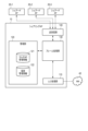
- FIG. 1 is a block diagram illustrating an example of a configuration of a communication system according to an embodiment.
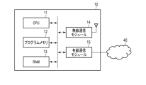
- FIG. 2 is a block diagram illustrating an example of a hardware configuration of a sharing AP according to the embodiment.
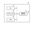
- FIG. 3 is a block diagram illustrating an example of a hardware configuration of a shared AP according to the embodiment.
- FIG. 4 is a block diagram illustrating an example of a hardware configuration of a terminal according to the embodiment.
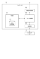
- FIG. 5 is a block diagram illustrating an example of a functional configuration of a sharing AP according to the embodiment.
- FIG. 6 is a block diagram illustrating an example of a functional configuration of a shared AP according to the embodiment.
- FIG. 7 is a block diagram illustrating an example of a functional configuration of the terminal according to the embodiment.
- FIG. 8 is a sequence diagram showing an example of allocation of transmission periods to a plurality of terminals in the communication system according to the embodiment.
- FIG. 9 is a flowchart illustrating an example of a
- FIG. 1 is a block diagram showing an example of the configuration of a communication system according to an embodiment.
- the communication system 1 includes a sharing AP (access point) 10, shared APs 20-1, 20-2, and 20-3, and terminals 30-1 and 30-2.
- the sharing AP 10 is connected to a network 40.
- the sharing AP 10 is, for example, a wireless LAN access point (AP).
- the sharing AP 10 is configured to perform wired or wireless communication with a server (not shown) on the network 40.
- the sharing AP 10 is configured to perform wired or wireless communication with each of the shared APs 20-1 to 20-3.
- Each of the shared APs 20-1 to 20-3 is, for example, a wireless LAN access point (AP).
- Each of the shared APs 20-1 to 20-3 is installed at a location physically separated from each other, and each of the shared APs 20-1 to 20-3 has a different communication area. In the example of FIG. 1, the communication area of each of the shared APs 20-1 to 20-3 at least partially overlaps with the communication area of the other shared APs.
- Each of the shared APs 20-1 to 20-3 is configured to wirelessly communicate with each of the terminals 30-1 and 30-2.
- Each of the shared APs 20-1 to 20-3 communicates with each of the terminals 30-1 and 30-2 in accordance with, for example, the IEEE 802.11 standard.
- the shared APs 20-1 to 20-3 have the same configuration. In the following, shared APs 20-1 to 20-3 may be referred to as shared AP 20 unless otherwise specified.
- Each of the terminals 30-1 and 30-2 is, for example, a wireless terminal such as a smartphone or a PC (Personal Computer).
- each of the terminals 30-1 and 30-2 is located within a communication area in which it can communicate with all of the shared APs 20-1 to 20-3. That is, the multiple APs 20-1 to 20-3 are common connection destinations for the wireless connections of the multiple terminals 30-1 and 30-2.
- Each of the terminals 30-1 and 30-2 is configured to communicate with a server on the network 40 by communicating with the sharing AP 10 via at least one of the shared APs 20-1 to 20-3. That is, each of the terminals 30-1 and 30-2 is connected to the sharing AP 10 via at least one of the shared APs 20-1 to 20-3.
- connection method between each of the terminals 30-1 and 30-2 and the sharing AP 10 as described above is also called a "multi-AP connection method.”
- Terminals 30-1 and 30-2 have the same configuration. In the following, when there is no particular distinction between terminals 30-1 and 30-2, they may be referred to as terminal 30.
- each of the terminals 30 is a wireless terminal that performs wireless communication using multiple channels (links).
- Each of the terminals 30 corresponds to a non-AP MLD and includes multiple affiliated STAs (stations).
- each of the terminals 30 includes three affiliated STAs.
- the terminal 30-1 is also indicated as non-AP MLD1, and includes three affiliated STAs A-STA1-1, A-STA1-2, and A-STA1-3.
- the terminal 30-2 is also indicated as non-AP MLD2, and includes three affiliated STAs A-STA2-1, A-STA2-2, and A-STA2-3.
- Each of the terminals 30 is an MLD (multi-link device) on the terminal 30 side that manages the state of the links established by each of the multiple affiliated STAs under its control.
- Each of the terminals 30 also performs processing to establish a connection with the sharing AP 10 in the multi-AP connection method.
- the sharing AP 10 can establish a connection (transmission path) between each of the terminals 30 (non-AP MLD) via the shared AP 20-1, the shared AP 20-2, and the shared AP 20-3. That is, each of the shared APs 20-1 to 20-3 is a candidate for a destination in data exchange between the sharing AP 10 and each of the terminals 30. Then, each of A-STA1-1 to A-STA1-3 of the terminal 30-1 and A-STA2-1 to A-STA2-3 of the terminal 30-2 exchanges data with the sharing AP 10 via one of the shared APs 20-1 to 20-3 that are candidate destinations.
- each of the terminals 30 is wirelessly connected to multiple shared APs 20 by multiple affiliated STAs.
- shared APs 20-1 to 20-3 are also referred to as access points that "belong" to sharing AP 10 in the multi-AP connection method.
- the sharing AP 10, the shared APs 20-1 to 20-3, and the terminals 30-1 and 30-2 have wireless communication functions based on, for example, the OSI (Open Systems Interconnection) reference model.
- the wireless communication functions are divided into seven layers (layer 1: physical layer, layer 2: data link layer, layer 3: network layer, layer 4: transport layer, layer 5: session layer, layer 6: presentation layer, layer 7: application layer).
- the data link layer includes the LLC (Logical Link Control) sublayer and the MAC (Media Access Control) sublayer.
- FIG. 2 is a block diagram showing an example of the hardware configuration of a sharing AP according to an embodiment.
- FIG. 2 shows an example of a case where the sharing AP 10 communicates wirelessly with each of the shared APs 20.
- the sharing AP 10 includes, for example, a CPU (Central Processing Unit) 11, a ROM (Read Only Memory) 12, a RAM (Random Access Memory) 13, a wireless communication module 14, and a wired communication module 15.
- a CPU Central Processing Unit
- ROM Read Only Memory
- RAM Random Access Memory
- the CPU 11 is a processing circuit that controls the overall operation of the sharing AP 10.
- the ROM 12 is, for example, a non-volatile semiconductor memory.
- the ROM 12 stores programs and data for controlling the sharing AP 10.
- the RAM 13 is, for example, a volatile semiconductor memory.
- the RAM 13 is used as a working area for the CPU 11.
- the wireless communication module 14 is a circuit used for transmitting and receiving data by wireless signals.
- the wireless communication module 14 is connected to an antenna.
- the wired communication module 15 is a circuit used for transmitting and receiving data by wired signals.
- the wireless communication module 14 can be connected (wirelessly connected) to the shared APs 20-1 to 20-3.
- the wired communication module 15 can be connected to the network 40.
- the sharing AP 10 communicates with each of the shared APs 20 via wired communication
- the sharing AP 10 is not provided with a wireless communication module 14.
- the wired communication module 15 can be connected to the network 40 and can also be connected (wired) to the shared APs 20-1 to 20-3.
- FIG. 3 is a block diagram showing an example of the hardware configuration of a shared AP according to an embodiment.
- FIG. 3 shows an example of a case where a shared AP 20 communicates wirelessly with a sharing AP 10.
- the shared AP 20 includes, for example, a CPU 21, a ROM 22, a RAM 23, and a wireless communication module 24.
- the CPU 21 is a processing circuit that controls the overall operation of the shared AP 20.
- the ROM 22 is, for example, a non-volatile semiconductor memory.
- the ROM 22 stores programs and data for controlling the shared AP 20.
- the RAM 23 is, for example, a volatile semiconductor memory.
- the RAM 23 is used as a working area for the CPU 21.
- the wireless communication module 24 is a circuit used for transmitting and receiving data by wireless signals.
- the wireless communication module 24 is connected to an antenna.
- the wireless communication module 24 can be connected (wirelessly connected) to the sharing AP 10 and the terminals 30-1 and 30-2.
- the shared AP 20 communicates with the sharing AP 10 via a wired connection
- the shared AP is further provided with a wired communication module (not shown).
- the wireless communication module 24 can be connected to the terminals 30-1 and 30-2, and the wired communication module can be connected (wired) to the sharing AP 10.
- FIG. 4 is a block diagram showing an example of the hardware configuration of a terminal according to an embodiment.
- the terminal 30 includes, for example, a CPU 31, a ROM 32, a RAM 33, a wireless communication module 34, a display 35, and storage 36.
- the CPU 31 is a processing circuit that controls the overall operation of the terminal 30.
- the ROM 32 is, for example, a non-volatile semiconductor memory.
- the ROM 32 stores programs and data for controlling the terminal 30.
- the RAM 33 is, for example, a volatile semiconductor memory.
- the RAM 33 is used as a working area for the CPU 31.
- the wireless communication module 34 is a circuit used for transmitting and receiving data by wireless signals.
- the wireless communication module 34 is connected to an antenna.
- the display 35 is, for example, an LCD (Liquid Crystal Display) or an EL (Electro-Luminescence) display.
- the display 35 displays a GUI (Graphical User Interface) corresponding to application software, etc.
- the storage 36 is a non-volatile storage device.
- the storage 36 stores system software, etc. of the terminal 30.
- FIG. 5 is a block diagram showing an example of the functional configuration of a sharing AP according to an embodiment.
- the sharing AP 10 functions as a computer including an LLC processing unit 110, a management unit 120, a frame processing unit 130, and a transmission/reception unit 140.
- the LLC processing unit 110 is a functional block that executes processes corresponding to the LLC sublayer of the second layer and layers 3 to 7.
- the management unit 120 and the frame processing unit 130 are functional blocks that execute processes corresponding to the MAC sublayer of the second layer.
- the transmission/reception unit 140 is a functional block that executes processes corresponding to the first layer.
- the LLC processing unit 110 which also functions as a data processing unit, generates an LLC packet by, for example, adding a DSAP (Destination Service Access Point) header or an SSAP (Source Service Access Point) header to data received from the network 40.
- the LLC processing unit 110 then inputs the generated LLC packet to the frame processing unit 130.
- the LLC processing unit 110 also extracts data from the LLC packet input from the frame processing unit 130.
- the LLC processing unit 110 then transmits the extracted data to the network 40.
- the management unit 120 controls the establishment of a connection (logical wireless connection) between the sharing AP 10 and each of the terminals 30 (non-AP MLD) in the multi-AP connection method.
- a connection logical wireless connection
- data is exchanged between the sharing AP 10 and each of the terminals 30 in a state in which each of the multiple affiliated STAs in each of the terminals 30-1 and 30-2 is wirelessly connected to one of the shared APs 20-1 to 20-3.
- the management unit 120 controls the establishment of a wireless connection between each of the multiple affiliated STAs and the corresponding shared AP 20 for each of the terminals 30.
- the wireless connection (link) between each of the affiliated STAs and the corresponding shared AP 20 is established, for example, by an association process.
- the management unit 120 also stores multi-AP management information 121 and terminal management information 122.
- the multi-AP management information 121 includes information about the access points used in the multi-AP connection method (i.e., the sharing AP 10 and the shared APs 20-1 to 20-3).
- the information about the access points used in the multi-AP connection method includes, for example, an identifier, a frequency band, and operation parameters.
- the identifier is, for example, the identifier of the corresponding AP.
- the identifier may include the MAC address of the corresponding AP.
- the frequency band includes information indicating the frequency band used by the corresponding AP in the multi-AP connection method.
- the frequency band for example, the 2.4 GHz band, the 5 GHz band, the 6 GHz band, the 45 GHz band, and the 60 GHz band may be applied.
- Each frequency band may include multiple channels.
- the multi-AP management information 121 may include channel information instead of or in addition to the frequency band information.
- Operation parameters include, for example, CWmin, CWmax, AIFS (arbitration interframe space), and TXOP (transmission opportunity) Limit.
- CWmin and CWmax indicate the minimum and maximum values of the contention window, respectively.
- the contention window is a parameter used to calculate backoff, which is a transmission waiting time for collision avoidance.
- AIFS is a fixed transmission waiting time set for each access category of traffic. Traffic access categories include, for example, "VO (Voice)", “VI (Video)”, “BE (Best Effort)", “BK (Background)", and "LL (Low Latency)".
- TXOP Limit indicates the upper limit of the channel occupancy period TXOP.
- the terminal management information 122 stores information about the terminals 30 (e.g., terminals 30-1, 30-2) connected to the sharing AP 10 in the multi-AP connection method. Specifically, the terminal management information 122 includes an identifier for the terminal 30 (non-AP MLD), and the respective identifiers of the affiliated STA of the terminal 30 and the shared AP 20 through which the connection with the terminal 30 is made.
- the identifier for the terminal 30 (non-AP MLD) may include the MAC address of the non-AP MLD.
- the identifier for the affiliated STA through which the connection with the terminal 30 is made may include the MAC address of the affiliated STA
- the identifier for the shared AP 20 through which the connection with the terminal 30 is made may include the MAC address of the shared AP 20.
- the frame processing unit 130 receives data from the LLC processing unit 110 as LLC packets.
- the sharing AP 10 communicates wirelessly with each of the shared APs 20
- the frame processing unit 130 generates a MAC frame by adding a MAC header to the LLC packet input from the LLC processing unit 110.
- the frame processing unit 130 then outputs the generated MAC frame to the transceiver unit 140.
- the sharing AP 10 communicates wirelessly with each of the shared APs 20
- the frame processing unit 130 extracts the LLC packet from the MAC frame input from the transceiver unit 140.
- the frame processing unit 130 then outputs the extracted LLC packet to the LLC processing unit 110.
- a MAC frame containing data is also referred to as a "data frame.”
- the frame processing unit 130 When the sharing AP 10 communicates with each of the shared APs 20 via wired communication, the frame processing unit 130 outputs the LLC packet input from the LLC processing unit 110 to the transceiver unit 140. The frame processing unit 130 also outputs the LLC packet input from the transceiver unit 140 to the LLC processing unit 110.
- management information is input to the frame processing unit 130 from the management unit 120, and the frame processing unit 130 outputs the management information from the management unit 120 to the transmission/reception unit 140.
- the management information includes notification information to be notified to either the shared AP 20 or the terminal 30, and control information related to control of the operation of either the shared AP 20 or the terminal 30.
- the management information may also include the multi-AP management information 121 and terminal management information 122 described above.
- the frame processing unit 130 also receives data and management information from the transmitting/receiving unit 140.
- the management information input from the transmitting/receiving unit 140 includes notification information and the like notified from either the shared AP 20 or the terminal 30.
- the frame processing unit 130 outputs the input data to the LLC processing unit 110.
- the frame processing unit 130 outputs the input notification information and the like to the management unit 120.
- a management frame which is a MAC frame including management information
- the frame processing unit 130 When the sharing AP 10 wirelessly communicates with each of the shared APs 20, a management frame, which is a MAC frame including management information, is input from the transmitting/receiving unit 140 to the frame processing unit 130, and the frame processing unit 130 outputs the management information included in the management frame from the transmitting/receiving unit 140 to the management unit 120.
- the transmitting/receiving unit 140 transmits and receives data, management information, etc., to and from each of the shared APs 20 to which it belongs by wireless or wired communication.
- the transmitting/receiving unit 140 has one or more wireless signal processing units.
- Each of the wireless signal processing units of the transmitting/receiving unit 140 generates a wireless frame by adding a preamble or the like to the MAC frame (data frame, management frame, etc.) input from the frame processing unit 130, and converts the generated wireless frame into a wireless signal.
- Each of the wireless signal processing units then transmits (radiates) the converted wireless signal via an antenna.
- the conversion process from a wireless frame to a wireless signal includes, for example, convolutional coding processing, interleaving processing, subcarrier modulation processing, inverse fast Fourier transform processing, OFDM modulation processing, and frequency conversion processing.
- each of the wireless signal processing units of the transceiver unit 140 converts a wireless signal received from one of the shared APs 20 via an antenna into a wireless frame.
- the process of converting a wireless signal into a wireless frame includes, for example, frequency conversion processing, OFDM demodulation processing, fast Fourier transform processing, subcarrier demodulation processing, deinterleaving processing, and Viterbi decoding processing.
- Each of the wireless signal processing units extracts a MAC frame from the converted wireless frame and outputs the extracted MAC frame to the frame processing unit 130.
- the same number of wireless signal processing units as the number of shared APs 20 to which it belongs are provided in the transceiver unit 140, with one corresponding wireless signal processing unit provided for each of the multiple shared APs. Data, etc. are then input from the frame processing unit 130 to the wireless signal processing unit corresponding to the shared AP 20 to which it is to be transmitted. Note that when multiple wireless signal processing units are provided in the transceiver unit 140 as in the example described above, the multiple wireless signal processing units are configured to transmit and receive wireless signals using different frequency bands or channels relative to each other.
- the transmission/reception unit 140 When the sharing AP 10 communicates with each of the shared APs 20 via a wired network, the transmission/reception unit 140 is connected to each of the shared APs 20 to which it belongs via a wired network, and transmits and receives data, management information, etc., between the sharing AP 10 and each of the shared APs 20 via the wired network.
- the transmission/reception unit 140 is configured from a network interface for the wired network.
- the management unit 120 works in cooperation with the shared AP 20 and terminal 30 (non-AP MLD) to which it belongs, to allocate (map) the traffic transmitted and received between the sharing AP 10 and the terminal 30. This allows traffic such as data transmitted from the sharing AP 10 to be allocated to the shared AP 20 to which it belongs. Based on the traffic allocation result, the management unit 120 instructs the frame processing unit 130 on the destination of the traffic. The frame processing unit 130 then causes the transmission/reception unit 140 to transmit the traffic to the shared AP 20 corresponding to the instruction from the management unit 120. The management unit 120 may also allocate traffic based on a traffic identifier (TID) associated with an access category.
- TID traffic identifier
- FIG. 6 is a block diagram showing an example of the functional configuration of a shared AP according to an embodiment.
- the shared AP 20 functions as a computer including a management unit 210, a frame processing unit 220, a transmission/reception unit 230, and a wireless signal processing unit 240.
- the management unit 210 and the frame processing unit 220 are functional blocks that execute processes corresponding to the MAC sublayer of the second layer.
- the wireless signal processing unit 240 is a functional block that executes processes corresponding to the first layer.
- the transmission/reception unit 230 is a functional block that executes processes corresponding to the first layer
- the transmission/reception unit 230 is a functional block that executes processes corresponding to the MAC sublayer of the second layer.
- the transmitting/receiving unit 230 transmits and receives data, management information, and the like to and from the sharing AP 10 by wireless or wired communication.
- the transmitting/receiving unit 230 is provided with a wireless signal processing unit.
- the wireless signal processing unit of the transmitting/receiving unit 230 generates a wireless frame by adding a preamble, etc. to the MAC frame (data frame, management frame, etc.) input from the frame processing unit 220.
- the wireless signal processing unit of the transmitting/receiving unit 230 then converts the generated wireless frame into a wireless signal, and transmits (radiates) the converted wireless signal to the sharing AP 10 via the antenna.
- the conversion process from a wireless frame to a wireless signal is performed as described above.
- the wireless signal processing unit of the transceiver unit 230 also converts the wireless signal received from the sharing AP 10 via the antenna into a wireless frame. The conversion process from the wireless signal to the wireless frame is performed as described above. The wireless signal processing unit extracts the MAC frame from the converted wireless frame and outputs the extracted MAC frame to the frame processing unit 220.
- the transmission/reception unit 230 When the shared AP 20 communicates with the sharing AP 10 via a wired network, the transmission/reception unit 230 is connected to the sharing AP 10 via a wired network, and transmits and receives data, management information, etc., between the sharing AP 20 and the sharing AP 10 via the wired network.
- the transmission/reception unit 230 is configured from a network interface for the wired network.
- the frame processing unit 220 When the shared AP 20 communicates with the sharing AP 10 via wired communication, the frame processing unit 220 generates a MAC frame including data or management information received by the transmission/reception unit 230 from the sharing AP 10. For example, the frame processing unit 220 adds a MAC header to the LLC packet received from the sharing AP 10 to generate a MAC frame (data frame).
- the frame processing unit 220 receives a data frame that will become a MAC frame from the wireless signal processing unit 240, it extracts an LLC packet from the input data frame and outputs the extracted LLC packet to the transmission/reception unit 230.
- the frame processing unit 220 also outputs management information from the management unit 210 to the transmission/reception unit 230.
- the transmission/reception unit 230 transmits the LLC packet and management information to the sharing AP 10 via wired communication.
- the wireless signal processing unit 240 can transmit and receive data, management information, and the like to and from the terminal 30 that is wirelessly connected via wireless communication. Therefore, the wireless signal processing unit 240 of the shared AP 20 can establish a wireless connection with each of the terminals 30 via one or more of the multiple links from that terminal 30.
- the wireless signal processing unit 240 generates a wireless frame by adding a preamble, etc. to the MAC frame (data frame, management frame, etc.) input from the frame processing unit 220.
- the wireless signal processing unit 240 then converts the generated wireless frame into a wireless signal, and transmits (radiates) the converted wireless signal to the corresponding terminal 30 via an antenna.
- the conversion process from a wireless frame to a wireless signal is performed as described above.
- the wireless signal processing unit 240 also converts the wireless signal received from the terminal 30 via the antenna into a wireless frame. The conversion process from the wireless signal to the wireless frame is performed as described above. The wireless signal processing unit 240 extracts the MAC frame from the converted wireless frame and outputs the extracted MAC frame to the frame processing unit 220.
- the wireless signal processing unit of the transceiver unit 230 is configured to transmit and receive using a frequency band or channel different from that of the wireless signal processing unit 240. Furthermore, when the shared AP 20 communicates wirelessly with the sharing AP 10, the transceiver unit 230 including the wireless signal processing unit does not need to be provided. In this case, the shared AP 20 communicates wirelessly with the sharing AP 10 via the wireless signal processing unit 240.
- the frame processing unit 220 outputs a data frame, which is a MAC frame, to the wireless signal processing unit 240.
- the frame processing unit 220 When management information is input from either the transmission/reception unit 230 or the wireless signal processing unit 240, the frame processing unit 220 outputs the input management information to the management unit 210.
- the frame processing unit 220 When management information to be notified to the sharing AP 10 is input from the management unit 210, the frame processing unit 220 outputs the input management information to the transmission/reception unit 230.
- the frame processing unit 220 When management information to be notified to the terminal 30 is input from the management unit 210, the frame processing unit 220 generates a beacon frame as a management frame from the input management information.
- the frame processing unit 220 then outputs the generated beacon frame to the wireless signal processing unit 240.
- the wireless signal converted from the beacon frame is then transmitted from the wireless signal processing unit 240, and the management information included in the beacon is notified to the terminal 30.
- the management information reported by the shared AP 20 via a beacon includes information about the sharing AP 10, information about the shared AP 20 of the own station, and information about the shared AP 20 of another station that belongs to the sharing AP 10.
- the shared AP 20 may receive the above-mentioned multi-AP management information 121 and terminal management information 122, etc. from the sharing AP 10, and the management unit 210 may report the multi-AP management information 121 and terminal management information 122, etc. via a beacon.
- the management unit 210 also stores link management information 211, which is connection management information, as management information related to the wireless connection of the terminal 30 in the multi-AP connection method.
- the link management information 211 includes an identifier of the terminal 30 wirelessly connected to the local shared AP 20.
- the link management information 211 indicates an identifier of an affiliated STA wirelessly connected to the local shared AP 20.
- the identifier of the terminal 30 may include the MAC address of the terminal 30, and the identifier of the affiliated STA may include the identifier of the affiliated STA.
- the transmitting/receiving unit 230 also receives instructions from the sharing AP 10 regarding the transmission of traffic (data) between the sharing AP 10 and the terminal 30 that is wirelessly connected to the local station.
- the management unit 210 controls data transmission (transmission and reception of data) between the sharing AP 10 and the terminal 30 that is wirelessly connected to the shared AP 20 of the local station in accordance with the instructions from the sharing AP 10.
- FIG. 7 is a block diagram showing an example of the functional configuration of a terminal according to an embodiment.
- the terminal 30 functions as a computer including an application execution unit 300, an LLC processing unit 310, a management unit 320, a frame processing unit 330, and radio signal processing units 340, 350, and 360.
- the application execution unit 300 is a functional block that executes processing corresponding to the seventh layer.
- the LLC processing unit 310 is a functional block that executes processing corresponding to the LLC sublayer of the second layer and layers 3 to 6.
- the management unit 320 and the frame processing unit 330 are functional blocks that execute processing corresponding to the MAC sublayer of the second layer.
- the radio signal processing units 340, 350, and 360 are functional blocks that execute processing corresponding to the MAC sublayer of the second layer and layer 1.
- the application execution unit 300 executes an application based on data input from the LLC processing unit 310.
- the application execution unit 300 also inputs data to the LLC processing unit 310.
- the application execution unit 300 can display application information on the display 35.
- the application execution unit 300 can also operate based on operations on an input interface.
- the LLC processing unit 310 which also functions as a data processing unit, generates an LLC packet by adding a DSAP header, SSAP header, etc. to the data input from the application execution unit 300.
- the LLC processing unit 310 then outputs the generated LLC packet to the frame processing unit 330.
- the LLC processing unit 310 also extracts data from the LLC packet input from the frame processing unit 330.
- the LLC processing unit 310 then outputs the extracted data to the application execution unit 300.
- the management unit 320 controls the connection (logical wireless connection) between the sharing AP 10 and its own terminal 30 (non-AP MLD) in the multi-AP connection method.
- the management unit 320 acquires the management information contained in the beacon by receiving a beacon from the shared AP 20 that is wirelessly connected.
- the management unit 320 acquires the multi-AP management information 121 and terminal management information 122, etc., described above, by receiving a beacon from the shared AP 20.
- the management unit 320 manages the management information contained in the beacon. Then, based on the management information, the management unit 320 controls the wireless connection between each of the multiple affiliated STAs and the shared AP 20 to which it is connected.
- the management unit 320 also stores link management information 321, which is connection management information.
- the link management information 321 indicates the identifier of the shared AP 20 to which each of the multiple affiliated STAs of the local terminal 30 is to be connected wirelessly.
- the identifier of the shared AP 20 may include the MAC address of the shared AP 20.
- the frame processing unit 330 adds a MAC header to the LLC packet input from the LLC processing unit 310 to generate a MAC frame.
- the frame processing unit 330 then distributes the generated MAC frame to the wireless signal processing units 340, 350, and 360. At this time, the MAC frame is output to one or more of the corresponding wireless signal processing units 340, 350, and 360.
- the frame processing unit 330 also extracts LLC packets or management information from the MAC frames input from each of the wireless signal processing units 340, 350, and 360.
- the frame processing unit 330 then outputs the LLC packets to the LLC processing unit 310 and outputs the management information to the management unit 320.
- the affiliated STAs A-STA1-1, A-STA1-2, and A-STA1-3 each include wireless signal processing units 340, 350, and 360.
- the affiliated STAs A-STA2-1, A-STA2-2, and A-STA2-3 each include wireless signal processing units 340, 350, and 360. Note that the wireless signal processing units 340, 350, and 360 have equivalent functional configurations.
- Each of the wireless signal processing units 340, 350, and 360 generates a wireless frame by adding a preamble, etc. to the MAC frame input from the frame processing unit 330. Then, each of the wireless signal processing units 340, 350, and 360 converts the generated wireless frame into a wireless signal, and transmits (radiates) the converted wireless signal via an antenna. The conversion process from the wireless frame to the wireless signal is performed as described above.
- each of the wireless signal processing units 340, 350, and 360 converts the wireless signal received from the corresponding shared AP 20 via the antenna into a wireless frame.
- the conversion process from the wireless signal to the wireless frame is performed as described above.
- Each of the wireless signal processing units 340, 350, and 360 extracts a MAC frame from the converted wireless frame and outputs the extracted MAC frame to the frame processing unit 330.
- the connection destinations of the wireless connections of the multiple terminals 30-1 and 30-2 are the shared APs 20-1 to 20-3, and the three shared APs 20-1 to 20-3 become common connection destinations for the multiple terminals 30.
- the wireless signal processing units 340, 350, and 360 wirelessly connect to the multiple shared APs 20 as common connection destinations for the multiple terminals 30 including the own station.
- the management unit 120 of the sharing AP 10 cooperates with the management unit 210 of the shared AP 20, etc., to assign a transmission period to each of the multiple terminals 30 that are wirelessly connected to the common connection destination. That is, a transmission period is set for each terminal 30 and for each non-AP MLD. During each transmission period, the terminal 30 to which the transmission period is assigned in real time is set as a single target terminal. Then, during each transmission period, data (traffic) is transmitted only to the single target terminal from the multiple shared APs 20 that serve as common connection destinations, and only the target terminal transmits data between the multiple shared APs 20 that serve as common connection destinations.
- terminals 30 other than the target terminal i.e., terminals 30 other than the terminals 30 to which the transmission period is assigned in real time
- the management unit 120 etc. assigns transmission periods to the multiple terminals 30 so that the transmission periods do not overlap in time between the multiple terminals 30. For this reason, a transmission period in which the multiple shared APs 20 that are common connection destinations transmit data only to one terminal 30 is time-shared with respect to a transmission period in which the multiple shared APs 20 transmit data only to another terminal 30.
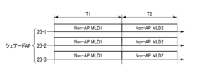
- FIG. 8 is a sequence diagram showing an example of the allocation of transmission periods to multiple terminals in a communication system according to an embodiment.
- a connection similar to the example of FIG. 1 is established between each of the terminals 30 and the sharing AP 10.
- a transmission period T1 during which data is transmitted only from the multiple shared APs 20-1 to 20-3 to the terminal 30-1 (non-AP MLD1), and a transmission period T2 during which data is transmitted only from the multiple shared APs 20-1 to 20-3 to the terminal 30-2 (non-AP MLD2) are set.
- the transmission period T1 is assigned to the terminal 30-1, and the transmission period T2 is assigned to the terminal 30-2.
- terminal 30-1 is set as the single target terminal that transmits data between shared APs 20-1 to 20-3, and terminal 30-2, which is not the target terminal, does not transmit data between shared APs 20-1 to 20-3.
- terminal 30-2 is set as the single target terminal that transmits data between shared APs 20-1 to 20-3, and terminal 30-1, which is not the target terminal, does not transmit data between shared APs 20-1 to 20-3.
- the transmission period T2 assigned to the terminal 30-2 starts at the end of the transmission period T1 assigned to the terminal 30-1, and the transmission periods T1 and T2 do not overlap in time. Then, when switching from the transmission period T1 to the transmission period T2, the transmission periods T1 and T2 are time-shared with respect to each other.
- the terminal 30 to which the transmission period is assigned switches from terminal 30-1 to terminal 30-2.
- the transmission period T1 switches to the transmission period T2
- the data transmission destination switches from terminal 30-1 to terminal 30-2. Therefore, for each of the shared APs 20-1 to 20-3, when the transmission period T1 switches to the transmission period T2, the period when the data transmission destination is terminal 30-1 is time-shared with respect to the period when the data transmission destination is terminal 30-2.
- each terminal 30 By allocating a transmission period to each terminal 30 (one non-AP MLD) as described above, data transmission between the target terminal to which the transmission period is allocated during each transmission period is synchronized among the multiple shared APs 20. In other words, the periods during which data is transmitted to the target terminal are synchronized among the multiple shared APs 20 that are commonly connected.
- transmission period T1 data transmission to terminal 30-1 is performed in synchronization among the multiple shared APs 20, and during transmission period T2, data transmission to terminal 30-2 is performed in synchronization among the multiple shared APs 20.
- the management unit 210 of each shared AP 20 cooperates with the sharing AP 10 and other shared APs 20, etc., to synchronize data transmission to the target terminal to which the transmission period is assigned in real time with the own station and the other shared APs 20, i.e., with the multiple shared APs 20 that are the common connection destinations.
- the management unit 320 of each terminal 30 cooperates with the sharing AP 10 and the multiple shared APs 20 that are the common connection destinations to synchronize data transmission to the own station, which is the target terminal, with the multiple shared APs 20 that are the common connection destinations, during the transmission period assigned to the own station.
- the management unit 120 of the sharing AP 10 cooperates with the shared APs 20 to which it belongs, etc., to switch the terminal 30 to which the transmission period is assigned, thereby synchronizing the timing of switching the terminal 30 that will be the destination of data transmission between the common connection destination and the multiple shared APs 20. That is, the timing of switching the terminal 30 that will be the destination of data transmission is synchronized in the multiple shared APs 20.
- the destination of data transmission is switched from terminal 30-1 to terminal 30-2 in synchronization with the multiple shared APs 20.
- the management unit 210 of each shared AP 20 cooperates with the sharing AP 10 and other shared APs 20 to switch the terminal 30 to which a transmission period is assigned, thereby synchronizing the timing at which the terminal 30 to which the data transmission is to be switched from its own station and the other shared APs 20, i.e., the multiple shared APs 20 that are the common connection destinations.
- the management unit 320 of each terminal 30 cooperates with the sharing AP 10 and the multiple shared APs 20 that are the common connection destinations to switch the terminal 30 to which a transmission period is assigned from its own station, thereby synchronizing the timing at which the terminal 30 to which the data transmission is to be switched from its own station to the multiple shared APs 20 that are the common connection destinations.
- the management unit 120 of the sharing AP 10 cooperates with the management unit 210 of the shared AP 20, etc. to monitor the status of the traffic to be sent to each terminal 30, and the status of the terminals 30 to which data (traffic) is to be transmitted.
- the traffic status for example, any of the traffic volume and the time required for transmission are measured for each traffic to be transmitted.
- the status of the terminals 30, for example, any of the transmission airtime, the number of frame transmissions, and the channel occupancy time are measured for each terminal 30 to which data is to be transmitted.
- the amount of traffic waiting to be transmitted at the terminal 30 and the degree of traffic congestion at the terminal 30 may be detected as the status of the terminal 30.
- a control device that bundles multiple sharing APs including sharing AP 10, and the control device controls the traffic status of each of the multiple sharing APs including sharing AP 10.
- the management unit 120 of the sharing AP 10 collects information about other sharing APs from the control device.
- the information about the other sharing APs includes the traffic status of other sharing APs and the status of data transmission between the other sharing APs and the terminal 30.
- the management unit 120 detects the status of the terminal 30, such as the degree of traffic congestion at the terminal 30, based on the information collected from the control device.
- the management unit 120 may notify the shared AP 20 to which it belongs of the information collected from the control device.
- the above-mentioned monitoring of the traffic to be transmitted and the status of the terminals 30, etc. that are the transmission targets is performed for a certain period of time by the management unit 120, etc. Then, the management unit 120, etc. decides the allocation of transmission periods to multiple terminals 30 based on the traffic and the status of the terminals 30, etc. detected by the monitoring. In one example, the allocation of transmission periods to terminals 30 is decided based on the channel occupancy time of each terminal 30 that is the target of data transmission. At this time, for example, the longer the channel occupancy time of a terminal 30, the higher the priority in allocating the transmission period.
- the management unit 120 When the allocation of transmission periods to the multiple terminals 30 is determined, the management unit 120 notifies the shared AP 20 and the terminals 30 of the allocation information for the determined transmission periods. Then, the management unit 320 of the multiple terminals 30 and the management unit 210 of the shared AP 20 that is the common connection destination of the multiple terminals 30 cooperate with each other to control data transmission based on the allocation information for the determined transmission periods. As a result, during each transmission period, the multiple shared APs 20 that are the common connection destination transmit data only with the single target terminal to which the transmission period is assigned. During each transmission period, the multiple shared APs 20 may transmit data with the target terminal using a normal scheme, or may transmit data using burst mode.
- the management unit 120 of the sharing AP 10 manages the transmission periods for which allocation has been decided.
- the management unit 120 notifies the start of the transmission period by sending a trigger to the terminal 30 that is the target terminal to which the transmission period is assigned at the start of each transmission period.
- the trigger also includes information on the end time of the started transmission period or the length of the started transmission period. Therefore, the terminal 30 that is the target terminal obtains information on the end of the started transmission period by receiving the trigger. Therefore, in this example, the management unit 120 manages and controls the transmission periods assigned to the multiple terminals 30 by sending a trigger to the terminal 30 that is the target terminal at the start of each transmission period.
- the management unit 120 may also manage and control the transmission periods assigned to the multiple terminals 30 by transmitting an RTS/CTS signal between the terminal 30 that is the target terminal instead of a trigger.
- the management unit 120 pre-specifies a period other than the transmission period as a NAV (Network Allocation Vector: transmission prohibition period) for each of the multiple terminals 30. Then, in each of the multiple terminals 30, the management unit 320 controls data transmission so that no data transmission is performed between the multiple shared APs 20 that are common connection destinations during the period specified as the NAV. Therefore, in this example, the management unit 120 manages and controls the transmission periods allocated to the multiple terminals 30 by pre-specifying a period other than the transmission period as a transmission prohibition period for each of the multiple terminals 30.
- NAV Network Allocation Vector: transmission prohibition period
- the management unit 320 of each of the multiple terminals 30 puts the terminal into a sleep state during periods other than the assigned transmission period.
- the management unit 120 of the sharing AP 10 may notify each of the multiple terminals 30 of a command to go into a sleep state during periods other than the transmission period by sending a trigger or the like.
- FIG. 9 is a flowchart showing an example of processing performed by the communication system according to the embodiment.
- the processing shown in the example of FIG. 9 is performed periodically in a state in which a plurality of shared APs 20 are common connection destinations for wireless connections of a plurality of terminals 30.
- the management unit 120 of the sharing AP 10 cooperates with the management units 210 of the shared APs 20, etc. to monitor the status of the traffic to be sent to each of the terminals 30, and the status of the terminals 30 to which data is to be transmitted (S51). Monitoring of the traffic status and the status of the terminals 30, etc. is performed as described above.
- the management unit 120 etc. determines the allocation of transmission periods to the multiple terminals 30 wirelessly connected to the common connection destination based on the traffic detected by monitoring and the status of the terminals 30 etc. (S52). At this time, the allocation of transmission periods to the multiple terminals 30 is determined as described above. The management unit 120 then notifies the shared AP 20 and the terminals 30 of the allocation information regarding the determined transmission periods (S53).
- the management unit 320 of the multiple terminals 30 and the management unit 210 of the shared AP 20 that is the common connection destination of the multiple terminals 30 cooperate with each other to control data transmission based on the allocation information for the determined transmission period (S54).
- the multiple shared APs 20 that are the common connection destination transmit data only with the single target terminal to which the transmission period is assigned.
- data transmission between the target terminal to which the transmission period is assigned is synchronized among the multiple shared APs 20.
- the timing at which the terminal 30 that is the data transmission destination is switched is synchronized among the multiple shared APs 20.
- data downstream data
- upstream data may also be transmitted from a target terminal to which a transmission period is assigned to multiple shared APs 20 that are common connection destinations during each transmission period.
- data may be transmitted from multiple shared APs 20 to a target terminal and data may be transmitted from the target terminal to multiple shared APs 20 during each transmission period.
- multiple shared APs 20 that are common connection destinations for multiple terminals 30 transmit data only with a single target terminal to which a transmission period is assigned during each transmission period, and do not transmit data with terminals 30 other than the target terminal.
- a transmission period during which data is transmitted between only a single target terminal (single target terminal group) and the multiple shared APs 20 that are common connection destinations is assigned to each terminal 30 (each terminal group) for the multiple terminals 30 that are wirelessly connected to the common connection destination. Then, during each transmission period, data transmission between the target terminal (target terminal group) to which the transmission period is assigned is synchronized by the multiple shared APs 20 that are common connection destinations.
- the timing of data transmission is prevented from shifting for each shared AP 20 that is the common connection destination in each of the multiple terminals 30 that are wirelessly connected to a common connection destination. Therefore, in data transmission between the sharing AP 10 and each of the terminals 30, a decrease in throughput is prevented, and an increase in data transmission time is prevented. Furthermore, during each transmission period, the multiple shared APs 20 that are the common connection destination transmit data only with the target terminal to which the transmission period is assigned, effectively preventing the upstream data transmitted from each terminal 30 from colliding with the upstream data from other terminals 30.
- a trigger is sent to the terminal 30 that is the target terminal, or a period other than the transmission period is designated in advance as a NAV (transmission prohibited period) in each of the multiple terminals 30.
- NAV transmission prohibited period
- each terminal 30 may be configured to have multiple affiliated STAs. That is, each terminal 30 may be configured to have two affiliated STAs, or four or more affiliated STAs.
- the shared APs 20-1 to 20-3 are common connection destinations for the wireless connections of the multiple terminals 30.
- a transmission period during which only a single target terminal (a single target terminal group) transmits data between the multiple terminals 30 that are common connection destinations and the multiple terminals 30 that are wirelessly connected to the common connection destination can be assigned to each terminal 30 (each terminal group). Then, during each transmission period, data transmission between the target terminals to which the transmission period is assigned is synchronized by the multiple shared APs 20 that are common connection destinations.
- a transmission period can be assigned to the multiple terminals 30 that are wirelessly connected to the common connection destination, similar to the above-mentioned embodiment, etc.
- a transmission period for transmitting data between the shared AP 20, which is a common connection destination for only a single target terminal (single target terminal group) is assigned to each terminal 30.
- multiple terminals 30 wirelessly connected to a common connection destination are grouped into multiple terminal groups.
- One or more terminals 30 belong to each of the multiple terminal groups.
- a transmission period is assigned to each terminal group for the multiple terminals 30 wirelessly connected to the common connection destination. Then, during each transmission period, only a single target terminal group transmits data with the shared AP 20 that is the common connection destination, and terminal groups other than the target terminal group are unable to transmit data with the shared AP 20 that is the common connection destination.
- each of the multiple grouped terminal groups has only one terminal 30, and a transmission period is assigned to each terminal 30, as in the above-mentioned embodiment.
- the multiple terminals 30 wirelessly connected to a common connection destination are grouped in a state in which the bias in traffic volume between the multiple terminal groups is minimized as much as possible.
- terminals 30 with high traffic volume and terminals 30 with low traffic volume are grouped in a state in which they belong to the same terminal group.
- each of the multiple terminals 30 wirelessly connected to the common connection destination corresponds to a non-AP MLD that establishes a wireless connection via multiple links, but the multiple terminals 30 wirelessly connected to the common connection destination may include a terminal 30 that establishes a wireless connection via only one link.
- the multiple terminals 30 wirelessly connected to the common connection destination may include a non-MLD STA that is a terminal 30 that has only one affiliated STA.
- a terminal 30 that is a non-MLD STA can establish a wireless connection only with one shared AP 20.
- a transmission period is assigned to the multiple terminals 30 wirelessly connected to the common connection destination for each terminal group. Then, during each transmission period, only a single target terminal group transmits data to the shared AP 20 that is the common connection destination, and terminal groups other than the target terminal group cannot transmit data to the shared AP 20 that is the common connection destination.
- the functions of the sharing AP and the shared AP are completely separate, but in a modified example, the sharing AP may have the functions of a shared AP.
- the sharing AP 10 may perform the processing of the shared AP 20-1 in addition to the processing described above.
- the sharing AP 10 has, as its functional configuration, a management unit 210, a frame processing unit 220, and a radio signal processing unit 240 in addition to the LLC processing unit 110, the management unit 120, the frame processing unit 130, and the transmission/reception unit 140.
- the transmitting/receiving unit 140 transmits and receives data, management information, etc., to and from each of the shared APs 20-2, 20-3, which are the shared APs 20 to which it belongs, by wireless or wired communication.
- the wireless signal processing unit 240 can transmit and receive data, management information, etc., to and from each of the terminals 30-1, 30-2 by wireless communication. Data, management information, etc. are exchanged between the frame processing unit 130 included in the functionality of the sharing AP 10 and the frame processing unit 220 included in the functionality of the shared AP.
- the sharing AP 10 having the functionality of a shared AP is provided, the sharing AP 10, the shared AP 20 belonging to the sharing AP 10, and the terminal 30 perform processing similar to that of the above-mentioned embodiment.
- connection between the sharing AP 10 and the terminal 30 goes through one shared AP, but in one modified example, the connection between the sharing AP 10 and the terminal 30 may go through two or more shared APs.
- processing of the above-described embodiment can also be applied to a multi-AP connection method with a multi-stage configuration in which two or more shared APs are interposed between the sharing AP and the terminal.
- the processes of the above-mentioned embodiments can be stored as a program that can be executed by a processor, which is a computer.
- the program that executes the above-mentioned processes can be stored in a storage medium of an external storage device, such as a magnetic disk, optical disk, or semiconductor memory, and distributed.
- the processor can then read the program stored in the storage medium of the external storage device, and have its operation controlled by the read program, thereby executing the processes of the embodiments.
- the present invention is not limited to the above-described embodiments, and can be modified in various ways during implementation without departing from the gist of the invention.
- the embodiments may also be implemented in appropriate combination, in which case the combined effects can be obtained.
- the above-described embodiments include various inventions, and various inventions can be extracted by combinations selected from the multiple constituent elements disclosed. For example, if the problem can be solved and an effect can be obtained even if some constituent elements are deleted from all the constituent elements shown in the embodiments, the configuration from which these constituent elements are deleted can be extracted as an invention.
Landscapes
- Engineering & Computer Science (AREA)
- Computer Networks & Wireless Communication (AREA)
- Signal Processing (AREA)
- Quality & Reliability (AREA)
- Mobile Radio Communication Systems (AREA)
Abstract
実施形態のシェアリングアクセスポイントでは、管理部は、1つ以上のシェアードアクセスポイントが複数の端末の無線接続の共通接続先となる状態において、複数の端末グループにグループ分けされた複数の端末に対して、単一の対象端末グループのみが共通接続先となるシェアードアクセスポイントとの間でデータ伝送する伝送期間を、1つの端末グループごとに割当てる。
Description
実施形態は、シェアリングアクセスポイント、シェアードアクセスポイント及び端末に関する。
アクセスポイント(AP:access point)と端末との間を無線で接続するシステムとして、無線LAN(Local Area Network)が知られている。無線LANでは、アソシエーション処理を行うことにより、端末とAPとの間が無線接続される。
また、IEEE802.11axの後継規格として策定中であるIEEE802.11beにおいては、端末は、APとの間に複数のリンクを確立し、複数のリンクのそれぞれを介してAPとの間でデータ伝送(データの送受信)を行うことが可能になる。また、複数のリンクを介して無線通信を行う端末では、端末からの複数のリンクを互いに対して異なるAPに無線接続することにより、1つの端末を複数のAPに対して無線接続可能となる。
複数のAPが用いられる環境に複数のリンクを介して通信を行う端末が複数存在する場合には、1つ以上のAPが複数の端末の無線接続の共通する共通接続先となる状態等が、発生し得る。1つ以上のAPが複数の端末の共通接続先となる状態では、スループットの低下、及び、データの送信時間の増大を抑制することが、求められている。
IEEE802.11be D3.0,"35.3 Multi-link operation",p479-p586,January 2023
本発明の目的は、1つ以上のAPが複数の端末の無線接続の共通接続先となる状態において、スループットの低下等を適切に抑制するシェアリングアクセスポイント、シェアードアクセスポイント及び端末を提供することにある。
本発明のある実施形態では、シェアリングアクセスポイントは、管理部を備え、管理部は、1つ以上のシェアードアクセスポイントが複数の端末の無線接続の共通接続先となる状態において、複数の端末グループにグループ分けされた複数の端末に対して、単一の対象端末グループのみが共通接続先となるシェアードアクセスポイントとの間でデータ伝送する伝送期間を、1つの端末グループごとに割当てる。
本発明によれば、1つ以上のAPが複数の端末の無線接続の共通接続先となる状態において、スループットの低下等を適切に抑制するシェアリングアクセスポイント、シェアードアクセスポイント及び端末を提供することができる。
以下、図面を参照して実施形態について説明する。なお、以下の説明において、同一の機能及び構成を有する構成要素については、共通する参照符号を付す。
図1は、実施形態に係る通信システムの構成の一例を示すブロック図である。図1に示すように、通信システム1は、シェアリング(sharing)AP(access point)10、シェアード(shared)AP20-1,20-2,20-3、及び、端末30-1,30-2を備える。シェアリングAP10は、ネットワーク40に接続されている。
シェアリングAP10は、例えば、無線LANのアクセスポイント(AP)である。シェアリングAP10は、ネットワーク40上のサーバ(図示しない)と有線通信又は無線通信するように構成される。シェアリングAP10は、シェアードAP20-1~20-3のそれぞれと無線通信又は有線通信するように構成される。
シェアードAP20-1~20-3のそれぞれは、例えば、無線LANのアクセスポイント(AP)である。シェアードAP20-1~20-3のそれぞれは、互いに物理的に離れた位置に設置され、シェアードAP20-1~20-3は、互いに対して異なる通信可能エリアを有する。図1の一例では、シェアードAP20-1~20-3のそれぞれの通信可能エリアは、他のシェアードAPの通信可能エリアと少なくとも一部が重複する。シェアードAP20-1~20-3のそれぞれは、端末30-1,30-2のそれぞれと無線通信するように構成される。シェアードAP20-1~20-3のそれぞれは、端末30-1,30-2のそれぞれに対して、例えばIEEE802.11規格に準拠して通信を行う。なお、シェアードAP20-1~20-3は、互いに同等の構成を有する。以下では、シェアードAP20-1~20-3を、特に区別しない場合、シェアードAP20のように記載する場合がある。
端末30-1,30-2のそれぞれは、例えば、スマートフォンやPC(Personal Computer)等の無線端末である。図1の一例では、端末30-1,30-2のそれぞれは、シェアードAP20-1~20-3の全てと通信可能な通信可能エリア内に位置する。すなわち、複数のAP20-1~20-3が、複数の端末30-1,30-2の無線接続の共通する共通接続先となる。端末30-1,30-2のそれぞれは、シェアードAP20-1~20-3の中の少なくとも1つを経由してシェアリングAP10と通信することにより、ネットワーク40上のサーバと通信するように構成される。すなわち、端末30-1,30-2のそれぞれは、シェアードAP20-1~20-3の中の少なくとも1つを経由して、シェアリングAP10に接続される。前述のような端末30-1,30-2のそれぞれとシェアリングAP10との間の接続方式は、“マルチAP接続方式”とも称される。なお、端末30-1,30-2は、互いに同等の構成を有する。以下では、端末30-1,30-2を、特に区別しない場合、端末30のように記載する場合がある。
また、端末30のそれぞれは、複数のチャネル(リンク)を利用して無線通信を実施する無線端末である。端末30のそれぞれは、non-AP MLDに相当し、複数のアフィリエイテッド(affiliated)STA(station)を含む。図1の一例では、端末30のそれぞれは、3つのアフィリエイテッドSTAを含む。そして、端末30-1は、non-AP MLD1とも示され、3つのアフィリエイテッドSTAとしてA-STA1-1,A-STA1-2及びA-STA1-3を含む。また、端末30-2は、non-AP MLD2とも示され、3つのアフィリエイテッドSTAとしてA-STA2-1,A-STA2-2及びA-STA2-3を含む。
端末30(non-AP MLD)のそれぞれは、配下の複数のアフィリエイテッドSTAのそれぞれが確立するリンクの状態を管理する端末30の側のMLD(multi-link device)である。端末30のそれぞれでは、マルチAP接続方式におけるシェアリングAP10との間の接続を確立するための処理も実施する。
図1の一例のように3つのシェアードAP20-1~20-3が設けられるマルチAP接続方式では、シェアリングAP10は、端末30(non-AP MLD)のそれぞれとの間に、シェアードAP20-1を介した接続(伝送経路)、シェアードAP20-2を介した接続(伝送経路)、及び、シェアードAP20-3を介した接続(伝送経路)のそれぞれを、確立可能である。すなわち、シェアードAP20-1~20-3のそれぞれは、シェアリングAP10と端末30のそれぞれとの間のデータ交換における経由先の候補となる。そして、端末30-1のA-STA1-1~A-STA1-3、及び、端末30-2のA-STA2-1~A-STA2-3のそれぞれは、経由先の候補となるシェアードAP20-1~20-3の中の1つを経由させて、シェアリングAP10とのデータ交換を実行する。
図1の一例では、シェアリングAP10と端末30-1(non-AP MLD1)との間のデータ交換において、A-STA1-1とシェアードAP20-1との間に確立されたリンク、A-STA1-2とシェアードAP20-2との間に確立されたリンク、及び、A-STA1-3とシェアードAP20-3との間に確立されたリンクが、用いられる。そして、シェアリングAP10と端末30-2(non-AP MLD2)との間のデータ交換において、A-STA2-1とシェアードAP20-1との間に確立されたリンク、A-STA2-2とシェアードAP20-2との間に確立されたリンク、及び、A-STA2-3とシェアードAP20-3との間に確立されたリンクが、用いられる。このため、端末30のそれぞれは、複数のアフィリエイテッドSTAによって、複数のシェアードAP20に無線接続される。なお、以下の説明では、シェアードAP20-1~20-3は、マルチAP接続方式においてシェアリングAP10に“帰属する”アクセスポイントとも称する。
シェアリングAP10、シェアードAP20-1~20-3、及び、端末30-1,30-2は、例えば、OSI(Open Systems Interconnection)参照モデルに基づく無線通信機能を有する。OSI参照モデルでは、無線通信機能が7階層(第1層:物理層、第2層:データリンク層、第3層:ネットワーク層、第4層:トランスポート層、第5層:セッション層、第6層:プレゼンテーション層、第7層:アプリケーション層)に分割される。データリンク層は、LLC(Logical Link Control)副層及びMAC(Media Access Control)副層を含む。
図2は、実施形態に係るシェアリングAPのハードウェア構成の一例を示すブロック図である。図2では、シェアリングAP10がシェアードAP20のそれぞれと無線通信する場合の一例を示す。図2に示すように、シェアリングAP10は、例えば、CPU(Central Processing Unit)11、ROM(Read Only Memory)12、RAM(Random Access Memory)13、無線通信モジュール14及び有線通信モジュール15を備える。
CPU11は、シェアリングAP10の全体の動作を制御する処理回路である。ROM12は、例えば、不揮発性の半導体メモリである。ROM12は、シェアリングAP10を制御するためのプログラム及びデータを記憶する。RAM13は、例えば、揮発性の半導体メモリである。RAM13は、CPU11の作業領域として使用される。無線通信モジュール14は、無線信号によるデータの送受信に使用される回路である。無線通信モジュール14は、アンテナに接続される。有線通信モジュール15は、有線信号によるデータの送受信に使用される回路である。無線通信モジュール14は、シェアードAP20-1~20-3に接続(無線接続)され得る。有線通信モジュール15は、ネットワーク40に接続され得る。
なお、シェアリングAP10がシェアードAP20のそれぞれと有線通信する場合は、シェアリングAP10に無線通信モジュール14が設けられない。この場合、有線通信モジュール15は、ネットワーク40に接続され得るとともに、シェアードAP20-1~20-3に接続(有線接続)され得る。
図3は、実施形態に係るシェアードAPのハードウェア構成の一例を示すブロック図である。図3では、シェアードAP20がシェアリングAP10と無線通信する場合の一例を示す。図3に示すように、シェアードAP20は、例えば、CPU21、ROM22、RAM23及び無線通信モジュール24を備える。
CPU21は、シェアードAP20の全体の動作を制御する処理回路である。ROM22は、例えば、不揮発性の半導体メモリである。ROM22は、シェアードAP20を制御するためのプログラム及びデータを記憶する。RAM23は、例えば、揮発性の半導体メモリである。RAM23は、CPU21の作業領域として使用される。無線通信モジュール24は、無線信号によるデータの送受信に使用される回路である。無線通信モジュール24は、アンテナに接続される。無線通信モジュール24は、シェアリングAP10及び端末30-1,30-2に接続(無線接続)され得る。
なお、シェアードAP20がシェアリングAP10と有線通信する場合は、シェアードAPに有線通信モジュール(図示しない)がさらに設けられる。この場合、無線通信モジュール24は、端末30-1,30-2に接続され得るとともに、有線通信モジュールは、シェアリングAP10に接続(有線接続)され得る。
図4は、実施形態に係る端末のハードウェア構成の一例を示すブロック図である。図4に示すように、端末30は、例えば、CPU31、ROM32、RAM33、無線通信モジュール34、ディスプレイ35及びストレージ36を備える。
CPU31は、端末30の全体の動作を制御する処理回路である。ROM32は、例えば、不揮発性の半導体メモリである。ROM32は、端末30を制御するためのプログラム及びデータを記憶する。RAM33は、例えば、揮発性の半導体メモリである。RAM33は、CPU31の作業領域として使用される。無線通信モジュール34は、無線信号によるデータの送受信に使用される回路である。無線通信モジュール34は、アンテナに接続される。ディスプレイ35は、例えばLCD(Liquid Crystal Display)又はEL(Electro-Luminescence)ディスプレイである。ディスプレイ35は、アプリケーションソフトに対応するGUI(Graphical User Interface)等を表示する。ストレージ36は、不揮発性の記憶装置である。ストレージ36は、端末30のシステムソフトウェア等を記憶する。
図5は、実施形態に係るシェアリングAPの機能構成の一例を示すブロック図である。図5に示すように、シェアリングAP10は、LLC処理部110、管理部120、フレーム処理部130、及び、送受信部140を備えるコンピュータとして機能する。LLC処理部110は、第2層のLLC副層及び第3層から第7層に対応する処理を実行する機能ブロックである。管理部120及びフレーム処理部130は、第2層のMAC副層に対応する処理を実行する機能ブロックである。また、シェアリングAP10がシェアードAP20のそれぞれと無線通信する場合は、送受信部140は第1層に対応する処理を実行する機能ブロックとなる。
データ処理部としても機能するLLC処理部110は、例えば、ネットワーク40から受信したデータにDSAP(Destination Service Access Point)ヘッダやSSAP(Source Service Access Point)ヘッダ等を付加して、LLCパケットを生成する。そして、LLC処理部110は、生成したLLCパケットを、フレーム処理部130に入力する。また、LLC処理部110は、フレーム処理部130から入力されたLLCパケットからデータを抽出する。そして、LLC処理部110は、抽出されたデータを、ネットワーク40に送信する。
管理部120は、マルチAP接続方式におけるシェアリングAP10と端末30(non-AP MLD)のそれぞれとの間の接続(論理的な無線接続)の確立を制御する。マルチAP接続方式では、端末30-1,30-2のそれぞれにおいて複数のアフィリエイテッドSTAのそれぞれがシェアードAP20-1~20-3のいずれか1つに無線接続された状態で、シェアリングAP10と端末30のそれぞれとの間でのデータ交換が行われる。管理部120は、端末30のそれぞれについて、複数のアフィリエイテッドSTAのそれぞれと対応するシェアードAP20との間の無線接続の確立を制御する。アフィリエイテッドSTAのそれぞれと対応するシェアードAP20との間の無線接続(リンク)は、例えば、アソシエーション処理によって、確立される。
また、管理部120には、マルチAP管理情報121及び端末管理情報122が記憶される。マルチAP管理情報121には、マルチAP接続方式に使用されるアクセスポイント(すなわち、シェアリングAP10及びシェアードAP20-1~20-3)に関する情報が含まれる。マルチAP接続方式に使用されるアクセスポイントに関する情報は、例えば、識別子、周波数帯及び運用パラメータ等を含む。
識別子は、例えば、対応するAPの識別子である。識別子は、対応するAPのMACアドレスを含んでいてもよい。周波数帯は、対応するAPがマルチAP接続方式において使用する周波数帯を示す情報を含む。周波数帯としては、例えば、2.4GHz帯、5GHz帯、6GHz帯、45GHz帯及び60GHz帯等が適用され得る。それぞれの周波数帯には、複数のチャネルが含まれてよい。この場合、マルチAP管理情報121は、周波数帯の情報に代えて、又は、周波数帯の情報に加えて、チャネルの情報を含んでいてよい。
運用パラメータは、例えば、CWmin、CWmax、AIFS(arbitration interframe space)及びTXOP(transmission opportunity)Limitを含む。CWmin及びCWmaxは、それぞれ、コンテンションウインドウの最小値及び最大値を示す。コンテンションウインドウは、衝突回避のための送信待ち時間であるバックオフの算出に用いられるパラメータである。AIFSは、トラヒックのアクセスカテゴリごとに設定される固定の送信待ち時間である。トラヒックのアクセスカテゴリは、例えば、“VO(Voice)”、“VI(Video)”、“BE(Best Effort)”、“BK(Background)”及び“LL(Low Latency)”を含む。TXOPLimitは、チャネルの占有期間TXOPの上限値を示す。
端末管理情報122には、マルチAP接続方式でシェアリングAP10と接続される端末30(例えば、端末30-1,30-2)に関する情報が記憶される。具体的には、端末管理情報122には、端末30(non-AP MLD)の識別子、及び、端末30との接続で経由する端末30のアフィリエイテッドSTA及びシェアードAP20のそれぞれの識別子が、含まれる。端末30(non-AP MLD)の識別子は、non-AP MLDのMACアドレスを含んでもよい。また、端末30との接続で経由するアフィリエイテッドSTAの識別子は、そのアフィリエイテッドSTAのMACアドレスを含んでもよく、端末30との接続で経由するシェアードAP20の識別子は、そのシェアードAP20のMACアドレスを含んでもよい。
フレーム処理部130には、LLC処理部110からのデータが、LLCパケットとして入力される。シェアリングAP10がシェアードAP20のそれぞれと無線通信する場合は、フレーム処理部130は、LLC処理部110から入力されたLLCパケットにMACヘッダを付加して、MACフレームを生成する。そして、フレーム処理部130は、生成したMACフレームを送受信部140に出力する。また、シェアリングAP10がシェアードAP20のそれぞれと無線通信する場合は、フレーム処理部130は、送受信部140から入力されたMACフレームからLLCパケットを抽出する。そして、フレーム処理部130は、抽出したLLCパケットをLLC処理部110に出力する。なお、以下の説明では、データを含むMACフレームは、“データフレーム”とも称する。
シェアリングAP10がシェアードAP20のそれぞれと有線通信する場合は、フレーム処理部130は、LLC処理部110から入力されたLLCパケットを送受信部140に出力する。また、フレーム処理部130は、送受信部140から入力されたLLCパケットをLLC処理部110に出力する。
また、フレーム処理部130には、管理部120から管理情報が入力され、フレーム処理部130は、管理部120からの管理情報を、送受信部140に出力する。管理情報には、シェアードAP20及び端末30のいずれかに通知する通知情報、及び、シェアードAP20及び端末30のいずれかの動作の制御に関する制御情報等が、含まれる。また、管理情報には、前述のマルチAP管理情報121及び端末管理情報122が含まれ得る。シェアリングAP10がシェアードAP20のそれぞれと無線通信する場合は、フレーム処理部130は、管理部120からの管理情報を含むMACフレームであるマネジメントフレームを生成し、生成したマネジメントフレームを送受信部140に出力する。
また、フレーム処理部130には、送受信部140からデータ及び管理情報が入力される。送受信部140から入力される管理情報には、シェアードAP20及び端末30のいずれかから通知される通知情報等が含まれる。送受信部140からデータがデータフレーム又はLLCパケットとして入力された場合は、フレーム処理部130は、入力されたデータをLLC処理部110に出力する。また、送受信部140から管理情報が入力された場合は、フレーム処理部130は、入力された通知情報等を管理部120に出力する。シェアリングAP10がシェアードAP20のそれぞれと無線通信する場合は、管理情報を含むMACフレームであるマネジメントフレームが送受信部140からフレーム処理部130に入力され、フレーム処理部130は、送受信部140からのマネジメントフレームに含まれる管理情報を管理部120に出力する。
送受信部140は、無線通信又は有線通信によって、帰属するシェアードAP20のそれぞれとの間で、データ及び管理情報等の送受信を行う。シェアリングAP10がシェアードAP20のそれぞれと無線通信する場合は、送受信部140は、1つ以上の無線信号処理部を備える。そして、送受信部140の無線信号処理部のそれぞれは、フレーム処理部130から入力されたMACフレーム(データフレーム及びマネジメントフレーム等)にプリアンブル等を付加して、無線フレームを生成し、生成した無線フレームを無線信号に変換する。そして、無線信号処理部のそれぞれは、変換した無線信号を、アンテナを介して送信(放射)する。無線フレームから無線信号への変換処理は、例えば、畳込符号化処理、インタリーブ処理、サブキャリア変調処理、逆高速フーリエ変換処理、OFDM変調処理及び周波数変換処理を含む。
また、送受信部140の無線信号処理部のそれぞれは、アンテナを介してシェアードAP20のいずれかから受信した無線信号を、無線フレームに変換する。無線信号から無線フレームへの変換処理は、例えば、周波数変換処理、OFDM復調処理、高速フーリエ変換処理、サブキャリア復調処理、デインタリーブ処理及びビタビ復号処理を含む。無線信号処理部のそれぞれは、変換した無線フレームからMACフレームを抽出し、抽出したMACフレームをフレーム処理部130に出力する。
ある一例では、帰属するシェアードAP20と同一の数の無線信号処理部が、送受信部140に設けられ、複数のシェアードAPのそれぞれに対して1つずつ、対応する無線信号処理部が設けられる。そして、送信先となるシェアードAP20に対応する無線信号処理部に、データ等がフレーム処理部130から入力される。なお、前述した例のように送受信部140に複数の無線信号処理部が設けられる場合、複数の無線信号処理部は、互いに対して異なる周波数帯又はチャネルを使用して無線信号を送受信するように構成されている。
シェアリングAP10がシェアードAP20のそれぞれと有線通信する場合は、送受信部140は、有線ネットワークを介して、帰属するシェアードAP20のそれぞれに接続され、有線ネットワークを介して、シェアードAP20のそれぞれとの間でデータ及び管理情報等を送受信する。この場合、送受信部140は、有線ネットワークのネットワークインタフェースから構成される。
管理部120は、帰属するシェアードAP20及び端末30(non-AP MLD)と協働して、シェアリングAP10と端末30との間で送受信されるトラヒックについての割当て(マッピング)を行う。これにより、シェアリングAP10から送信されるデータ等のトラヒックについて、帰属するシェアードAP20への割当てが、行われる。管理部120は、トラヒックについての割当て結果に基づいて、トラヒックの送信先をフレーム処理部130に指示する。そして、フレーム処理部130は、管理部120からの指示に対応するシェアードAP20に、トラヒックを送受信部140から送信させる。なお、管理部120は、アクセスカテゴリと対応づけられるTID(traffic identifier)に基づいて、トラヒックについての割当てを行ってもよい。
図6は、実施形態に係るシェアードAPの機能構成の一例を示すブロック図である。シェアードAP20は、管理部210、フレーム処理部220、送受信部230、及び、無線信号処理部240を備えるコンピュータとして機能する。管理部210及びフレーム処理部220は、第2層のMAC副層に対応する処理を実行する機能ブロックである。無線信号処理部240は、第1層に対応する処理を実行する機能ブロックである。また、シェアリングAP10がシェアードAP20のそれぞれと無線通信する場合は、送受信部230は第1層に対応する処理を実行する機能ブロックとなり、シェアリングAP10がシェアードAP20のそれぞれと有線通信する場合は、送受信部230は第2層のMAC副層に対応する処理を実行する機能ブロックとなる。
送受信部230は、無線通信又は有線通信によって、シェアリングAP10との間で、データ及び管理情報等の送受信を行う。シェアードAP20がシェアリングAP10と無線通信する場合は、送受信部230は、無線信号処理部を備える。そして、送受信部230の無線信号処理部は、フレーム処理部220から入力されたMACフレーム(データフレーム及びマネジメントフレーム等)にプリアンブル等を付加して、無線フレームを生成する。そして、送受信部230の無線信号処理部は、生成した無線フレームを無線信号に変換し、変換した無線信号を、アンテナを介してシェアリングAP10へ送信(放射)する。無線フレームから無線信号への変換処理は、前述のようにして行われる。
また、送受信部230の無線信号処理部は、アンテナを介してシェアリングAP10から受信した無線信号を、無線フレームに変換する。無線信号から無線フレームへの変換処理は、前述したようにして行われる。無線信号処理部は、変換した無線フレームからMACフレームを抽出し、抽出したMACフレームをフレーム処理部220に出力する。
シェアードAP20がシェアリングAP10と有線通信する場合は、送受信部230は、有線ネットワークを介して、シェアリングAP10に接続され、有線ネットワークを介して、シェアリングAP10との間でデータ及び管理情報等を送受信する。この場合、送受信部230は、有線ネットワークのネットワークインタフェースから構成される。
シェアードAP20がシェアリングAP10と有線通信する場合、フレーム処理部220は、送受信部230がシェアリングAP10から受信したデータ又は管理情報等を含むMACフレームを生成する。例えば、フレーム処理部220は、シェアリングAP10から受信したLLCパケットにMACヘッダを付加し、MACフレーム(データフレーム)を生成する。また、シェアードAP20がシェアリングAP10と有線通信する場合、フレーム処理部220は、無線信号処理部240からMACフレームとなるデータフレームが入力された場合、入力されたデータフレームからLLCパケットを抽出し、抽出したLLCパケットを送受信部230に出力する。また、フレーム処理部220は、管理部210からの管理情報を、送受信部230に出力する。そして、送受信部230は、LLCパケット及び管理情報等を、有線通信によってシェアリングAP10に送信する。
無線信号処理部240は、無線通信によって、無線接続されている端末30との間で、データ及び管理情報等を送受信可能である。このため、シェアードAP20の無線信号処理部240は、端末30のそれぞれに対して、その端末30からの複数のリンクのいずれか1つ以上を介して、無線接続を確立可能である。無線信号処理部240は、フレーム処理部220から入力されたMACフレーム(データフレーム及びマネジメントフレーム等)にプリアンブル等を付加して、無線フレームを生成する。そして、無線信号処理部240は、生成した無線フレームを無線信号に変換し、変換した無線信号を、アンテナを介して対応する端末30へ送信(放射)する。無線フレームから無線信号への変換処理は、前述のようにして行われる。
また、無線信号処理部240は、アンテナを介して端末30から受信した無線信号を、無線フレームに変換する。無線信号から無線フレームへの変換処理は、前述したようにして行われる。無線信号処理部240は、変換した無線フレームからMACフレームを抽出し、抽出したMACフレームをフレーム処理部220に出力する。
なお、シェアードAP20がシェアリングAP10と無線通信する場合、送受信部230の無線信号処理部は、無線信号処理部240とは異なる周波数帯又はチャネルを使用して送受信をする構成であることが、好ましい。また、シェアードAP20がシェアリングAP10と無線通信する場合、無線信号処理部を含む送受信部230は、設けられなくてもよい。この場合、シェアードAP20は、無線信号処理部240を介して、シェアリングAP10との間で無線通信を行う。
フレーム処理部220は、MACフレームであるデータフレームを無線信号処理部240に出力する。フレーム処理部220は、管理情報が送受信部230及び無線信号処理部240のいずれかから入力された場合、入力された管理情報を、管理部210に出力する。また、フレーム処理部220は、シェアリングAP10へ通知する管理情報が管理部210から入力された場合、入力された管理情報を送受信部230に出力する。フレーム処理部220は、端末30へ通知する管理情報が管理部210から入力された場合、入力された管理情報からビーコンフレームをマネジメントフレームとして生成する。そして、フレーム処理部220は、生成したビーコンフレームを、無線信号処理部240に出力する。そして、ビーコンフレームを変換した無線信号が、無線信号処理部240から送信されることにより、ビーコンに含まれる管理情報が端末30に報知される。
シェアードAP20からビーコンによって報知される管理情報には、シェアリングAP10に関する情報、自局のシェアードAP20に関する情報、シェアリングAP10に帰属する他局のシェアードAP20に関する情報が含まれる。また、シェアードAP20は、前述のマルチAP管理情報121及び端末管理情報122等をシェアリングAP10から受信し、管理部210は、ビーコンによってマルチAP管理情報121及び端末管理情報122等を報知させてもよい。
また、管理部210には、マルチAP接続方式における端末30の無線接続に関する管理情報として、接続管理情報であるリンク管理情報211が記憶される。リンク管理情報211には、自局のシェアードAP20に無線接続されている端末30の識別子が、含まれる。そして、自局のシェアードAP20に無線接続されている端末30に関しては、自局のシェアードAP20に無線接続されているアフィリエイテッドSTAの識別子が、リンク管理情報211において示される。端末30の識別子は、その端末30のMACアドレスを含んでもよく、アフィリエイテッドSTAの識別子は、そのアフィリエイテッドSTAの識別子を含んでもよい。
また、送受信部230は、自局に無線接続されている端末30との間でのトラヒック(データ)の伝送に関する指示を、シェアリングAP10から受信する。管理部210は、シェアリングAP10からの指示に従って、自局のシェアードAP20に無線接続されている端末30との間でのデータ伝送(データの送受信)を、制御する。
図7は、実施形態に係る端末の機能構成の一例を示すブロック図である。端末30は、アプリケーション実行部300、LLC処理部310、管理部320、フレーム処理部330、及び、無線信号処理部340,350,360を備えるコンピュータとして機能する。アプリケーション実行部300は、第7層に対応する処理を実行する機能ブロックである。LLC処理部310は、第2層のLLC副層及び第3層から第6層に対応する処理を実行する機能ブロックである。管理部320及びフレーム処理部330は、第2層のMAC副層に対応する処理を実行する機能ブロックである。無線信号処理部340,350,360は、第2層のMAC副層及び第1層に対応する処理を実行する機能ブロックである。
アプリケーション実行部300は、LLC処理部310から入力されたデータに基づき、アプリケーションを実行する。また、アプリケーション実行部300は、LLC処理部310にデータを入力する。例えば、アプリケーション実行部300は、アプリケーションの情報をディスプレイ35に表示することができる。また、アプリケーション実行部300は、入力インタフェースの操作に基づいて動作し得る。
データ処理部としても機能するLLC処理部310は、アプリケーション実行部300から入力されたデータにDSAPヘッダやSSAPヘッダ等を付加して、LLCパケットを生成する。そして、LLC処理部310は、生成したLLCパケットを、フレーム処理部330に出力する。また、LLC処理部310は、フレーム処理部330から入力されたLLCパケットからデータを抽出する。そして、LLC処理部310は、抽出されたデータを、アプリケーション実行部300に出力する。
管理部320は、マルチAP接続方式におけるシェアリングAP10と自局の端末30(non-AP MLD)との間の接続(論理的な無線接続)を制御する。端末30では、無線接続されているシェアードAP20からのビーコンを受信することにより、管理部320は、ビーコンに含まれる管理情報を取得する。ある一例では、端末30において、シェアードAP20からのビーコンを受信することにより、前述のマルチAP管理情報121及び端末管理情報122等を管理部320が取得する。管理部320は、ビーコンに含まれる管理情報を管理する。そして、管理部320は、管理情報に基づいて、複数のアフィリエイテッドSTAのそれぞれと接続先となるシェアードAP20との無線接続を、制御する。
また、管理部320には、接続管理情報であるリンク管理情報321が記憶される。リンク管理情報321では、自局の端末30の複数のアフィリエイテッドSTAのそれぞれについて、無線接続の接続先となるシェアードAP20の識別子が示される。シェアードAP20の識別子は、そのシェアードAP20のMACアドレスを含んでもよい。
フレーム処理部330は、LLC処理部310から入力されたLLCパケットにMACヘッダを付加して、MACフレームを生成する。そして、フレーム処理部330は、生成したMACフレームの無線信号処理部340,350,360への振分けを行う。この際、MACフレームは、無線信号処理部340,350,360の対応する1つ以上に、出力される。また、フレーム処理部330は、無線信号処理部340,350,360のそれぞれから入力されたMACフレームからLLCパケット又は管理情報を抽出する。そして、フレーム処理部330は、LLCパケットをLLC処理部310に出力するとともに、管理情報を管理部320に出力する。
図1の一例の端末30-1では、アフィリエイテッドSTAであるA-STA1-1,A-STA1-2,A-STA1-3は、それぞれ、無線信号処理部340,350,360を含む。そして、端末30-2では、アフィリエイテッドSTAであるA-STA2-1,A-STA2-2,A-STA2-3は、それぞれ、無線信号処理部340,350,360を含む。なお、無線信号処理部340,350,360は、互いに対して同等の機能構成となる。
無線信号処理部340,350,360のそれぞれは、フレーム処理部330から入力されたMACフレームにプリアンブル等を付加して、無線フレームを生成する。そして、無線信号処理部340,350,360のそれぞれは、生成した無線フレームを無線信号に変換し、変換した無線信号を、アンテナを介して送信(放射)する。無線フレームから無線信号への変換処理は、前述したようにして行われる。
また、無線信号処理部340,350,360のそれぞれは、対応するシェアードAP20からアンテナを介して受信した無線信号を無線フレームに変換する。無線信号から無線フレームへの変換処理は、前述したようにして行われる。無線信号処理部340,350,360のそれぞれは、変換した無線フレームからMACフレームを抽出し、抽出したMACフレームをフレーム処理部330に出力する。
前述のようなマルチAP接続方式の通信システム1では、複数のシェアードAP20が用いられる環境に、複数のリンクを介して無線通信を行う端末30が複数存在し得る。この場合は、1つ以上のシェアードAP20が複数の端末30の無線接続の共通する共通接続先となる状態が、発生し得る。例えば、図1の一例では、複数の端末30-1,30-2において、無線接続の接続先がシェアードAP20-1~20-3となり、3つのシェアードAP20-1~20-3が、複数の端末30で共通する共通接続先となる。この際、シェアードAP20のそれぞれでは、自局を含む複数のシェアードAP20が、複数の端末30の無線接続の共通接続先として共通する状況となる。そして、端末30のそれぞれでは、自局を含む複数の端末30の共通接続先として複数のシェアードAP20に、無線信号処理部340,350,360によって無線接続される状況となる。
以下、複数のシェアードAP20が複数の端末30で共通する共通接続先となる状態において、シェアリングAP10、シェアードAP20及び端末30によって行われる処理について、説明する。そして、図1等のように3つのシェアードAP20-1~20-3が複数の端末30の共通接続先となる状態を一例として、説明する。また、以下の説明では、シェアリングAP10からシェアードAP20のいずれかを経由して端末30へデータ伝送する場合、すなわち、下りデータを伝送する場合について、説明する。
複数のシェアードAP20が複数の端末30の共通接続先となる状態では、シェアリングAP10の管理部120は、シェアードAP20の管理部210等と協働して、共通接続先に無線接続される複数の端末30に対して、伝送期間を1つの端末30ごとに割当てる。すなわち、1つの端末30ごとに、1つのnon-AP MLDごとに、伝送期間が設定される。伝送期間のそれぞれでは、リアルタイムで伝送期間が割当てられている端末30が、単一の対象端末として設定される。そして、伝送期間のそれぞれでは、単一の対象端末へのみ、共通接続先となる複数のシェアードAP20からデータ(トラヒック)が伝送され、対象端末のみが、共通接続先となる複数のシェアードAP20との間でデータ伝送する。
また、伝送期間のそれぞれでは、対象端末以外の端末30、すなわち、リアルタイムで伝送期間が割当てられている端末30以外の端末30は、共通接続先となる複数のシェアードAP20との間でのデータ伝送を行わない。また、管理部120等は、複数の端末30の間で伝送期間が時間的に重複しない状態に、複数の端末30に対して伝送期間を割当てる。このため、共通接続先となる複数のシェアードAP20がある1つの端末30へのみデータ伝送する伝送期間は、複数のシェアードAP20が別のある1つの端末30へのみデータ伝送する伝送期間に対して、時分割される。
図8は、実施形態に通信システムにおいて、複数の端末に対する伝送期間の割当ての一例を示すシーケンス図である。図8の一例では、端末30のそれぞれとシェアリングAP10との間において、図1の一例と同様の接続が確立される。そして、複数のシェアードAP20-1~20-3から端末30-1(non-AP MLD1)へのみデータが伝送される伝送期間とT1、及び、複数のシェアードAP20-1~20-3から端末30-2(non-AP MLD2)へのみデータが伝送される伝送期間T2が、設定される。そして、端末30-1に、伝送期間T1が割当てられ、端末30-2に、伝送期間T2が割当てられる。
伝送期間T1では、端末30-1が、シェアードAP20-1~20-3との間でデータ伝送する単一の対象端末に設定され、対象端末以外の端末30-2は、シェアードAP20-1~20-3との間でのデータ伝送を行わない。また、伝送期間T2では、端末30-2が、シェアードAP20-1~20-3との間でデータ伝送する単一の対象端末に設定され、対象端末以外の端末30-1は、シェアードAP20-1~20-3との間でのデータ伝送を行わない。
また、図8の一例では、端末30-1に割当てられる伝送期間T1の終了時から、端末30-2に割当てられる伝送期間T2が開始され、伝送期間T1,T2は、時間的に重複しない。そして、伝送期間T1から伝送期間T2への切替わり時において、伝送期間T1,T2は、互いに対して時分割される。
また、図8の一例では、伝送期間T1から伝送期間T2への切替わり時において、伝送期間が割当てられる端末30が、端末30-1から端末30-2へ切替わる。そして、端末30の共通接続先となる複数のシェアードAP20-1~20-3のそれぞれでは、伝送期間T1から伝送期間T2への切替わり時において、データ伝送の相手先が、端末30-1から端末30-2に切替わる。したがって、シェアードAP20-1~20-3のそれぞれについては、伝送期間T1から伝送期間T2への切替わり時において、データ伝送の相手先が端末30-1となる期間が、データ伝送の相手先が端末30-2となる期間に対して、時分割される。
前述のようにして1つ端末30(1つのnon-AP MLD)ごとに伝送期間を割当てることにより、伝送期間のそれぞれでは、伝送期間が割当てられている対象端末との間でのデータ伝送が、複数のシェアードAP20で同期する。すなわち、対象端末へデータを送信する期間が、共通接続先となる複数のシェアードAP20で時間的に揃う。図8の一例では、伝送期間T1において、端末30-1へのデータ伝送が、複数のシェアードAP20で同期して行われ、伝送期間T2において、端末30-2へのデータ伝送が、複数のシェアードAP20で同期して行われる。
伝送期間のそれぞれでは、シェアードAP20のそれぞれの管理部210は、シェアリングAP10及び他のシェアードAP20等と協働して、リアルタイムで伝送期間が割当てられている対象端末へのデータ伝送を、自局及び他のシェアードAP20で、すなわち、共通接続先となる複数のシェアードAP20で同期させる。そして、端末30のそれぞれの管理部320は、シェアリングAP10及び共通接続先となる複数のシェアードAP20と協働して、自局に割当てられた伝送期間において、対象端末となる自局へのデータ伝送を、共通接続先となる複数のシェアードAP20で同期させる。
また、シェアリングAP10の管理部120は、帰属するシェアードAP20等と協働して、伝送期間が割当てられる端末30を切替えることにより、データ伝送の相手先となる端末30が切替わるタイミングを、共通接続先と複数のシェアードAP20で同期させる。すなわち、複数のシェアードAP20において、データ伝送の相手先となる端末30が切替わるタイミングを時間的に揃える。図8の一例では、伝送期間T1から伝送期間T2への切替わり時において、データ伝送の相手先が、端末30-1から端末30-2へ、複数のシェアードAP20で同期して切替わる。
シェアードAP20のそれぞれの管理部210は、シェアリングAP10及び他のシェアードAP20等と協働して、伝送期間が割当てられる端末30を切替えることにより、データ伝送の相手先となる端末30が切替わるタイミングを、自局及び他のシェアードAP20で、すなわち、共通接続先となる複数のシェアードAP20で同期させる。そして、端末30のそれぞれの管理部320は、シェアリングAP10及び共通接続先となる複数のシェアードAP20と協働して、伝送期間が割当てられる端末30を自局からの切替えることにより、データ伝送の相手先となる端末30が自局から切替わるタイミングを、共通接続先となる複数のシェアードAP20で同期させる。
共通接続先に無線接続される複数の端末30に対する伝送期間の割当てを決定する際には、シェアリングAP10の管理部120は、シェアードAP20等の管理部210と協働して、端末30のそれぞれへ送信するトラヒックの状況、及び、データ(トラヒック)の伝送対象となる端末30の状況等を、モニタリングする。トラヒックの状況としては、例えば、送信するトラヒックのそれぞれに関して、トラヒック量及び送信に要する時間等のいずれかが、測定される。端末30の状況としては、例えば、データの伝送対象となる端末30のそれぞれに関して、送信エアタイム、フレーム送信回数及びチャネル占有時間のいずれかが、測定される。また、測定したチャネル占有時間等から、端末30における送信待機中のトラヒック量、及び、端末30におけるトラヒックの混み具合等を、端末30の状況として検出してもよい。
また、ある一例では、シェアリングAP10を含む複数のシェアリングAPを束ねる制御装置が設けられ、制御装置によって、シェアリングAP10を含む複数のシェアリングAPのそれぞれのトラヒックの状況等が、制御される。この場合、シェアリングAP10の管理部120は、制御装置から、他のシェアリングAPに関する情報を、収集する。他のシェアリングAPに関する情報には、他のシェアリングおけるトラヒックの状況、及び、他のシェアリングAPと端末30との間でのデータ伝送の状況等が、含まれる。そして、管理部120は、制御装置から収取した情報等に基づいて、端末30におけるトラヒックの混み具合等の端末30の状況を検出する。なお、本一例では、管理部120は、制御装置から収集した情報を、帰属するシェアードAP20に通知してもよい。
本実施形態では、送信するトラヒック及び伝送対象となる端末30等の状況についての前述のモニタリングが、管理部120等によって、一定期間行われる。そして、管理部120等は、モニタリングによって検出されたトラヒック及び端末30等の状況に基づいて、複数の端末30に対する伝送期間の割当てを決定する。ある一例では、データの伝送対象となる端末30のそれぞれのチャネル占有時間に基づいて、端末30に対する伝送期間の割当てが決定される。この際、例えば、チャネル占有時間が長い端末30ほど、伝送期間が優先して割当てられる。
複数の端末30に対する伝送期間の割当てを決定すると、管理部120は、決定した伝送期間についての割り当て情報を、シェアードAP20及び端末30に通知する。そして、複数の端末30の管理部320、及び、複数の端末30の共通接続先となるシェアードAP20の管理部210は、互いに対して協働して、決定された伝送期間についての割当て情報に基づいて、データ伝送を制御する。これにより、伝送期間のそれぞれにおいて、共通接続先となる複数のシェアードAP20は、伝送期間が割当てられている単一の対象端末との間でのみ、データ伝送を行う。伝送期間のそれぞれでは、複数のシェアードAP20は、対象端末との間で、通常のスキームでデータ伝送を行ってもよく、バーストモードを利用してデータ伝送を行ってよい。
シェアリングAP10の管理部120は、割当てが決定された伝送期間を管理する。ある一例では、管理部120は、伝送期間のそれぞれの開始時に、伝送期間が割当てられる対象端末となる端末30に対して、トリガーを送信することによって、伝送期間の開始を通知する。また、トリガーには、開始される伝送期間の終了時刻又は開始される伝送期間の長さに関する情報が、含まれる。このため、対象端末となる端末30は、トリガーを受信することにより、開始された伝送期間の終了に関する情報を取得する。したがって、本一例では、管理部120は、伝送期間のそれぞれの開始時に対象端末となる端末30に対してトリガーを送信することにより、複数の端末30に対して割当てられる伝送期間を管理及び制御する。また、管理部120は、トリガーの代わりにRTS/CTS信号を対象端末となる端末30との間で伝送することにより、複数の端末30に対して割当てられる伝送期間を管理及び制御してもよい。
また、別のある一例では、管理部120は、複数の端末30のそれぞれに対して、伝送期間以外の期間を、NAV(Network Allocation Vector:送信禁止期間)として、予め指定する。そして、複数の端末30のそれぞれでは、管理部320は、NAVとして指定された期間において、共通接続先となる複数のシェアードAP20との間でデータ伝送を行わない状態に、データ伝送を制御する。したがって、本一例では、管理部120は、複数の端末30のそれぞれに対して伝送期間以外の期間を伝送禁止期間として予め指定することにより、複数の端末30に対して割当てられる伝送期間を管理及び制御する。
また、ある一例では、複数の端末30のそれぞれの管理部320は、割当てられた伝送期間以外の期間において、自局をスリープ(sleep)状態にする。この場合、シェアリングAP10の管理部120は、トリガー等を送信させることによって、伝送期間以外の期間においてスリープ状態になる指令を、複数の端末30のそれぞれへ通知してもよい。
図9は、実施形態に係る通信システムによって行われる処理の一例を示すフローチャートである。図9の一例に示す処理は、複数のシェアードAP20が複数の端末30の無線接続の共通接続先となる状態において、定期的に行われる。図9の一例の処理を開始すると、シェアリングAP10の管理部120は、シェアードAP20等の管理部210と協働して、端末30のそれぞれへ送信するトラヒックの状況、及び、データの伝送対象となる端末30の状況等を、モニタリングする(S51)。トラヒックの状況及び端末30の状況等のモニタリングは、前述したようにして行われる。
そして、管理部120等は、モニタリングによって検出されたトラヒック及び端末30等の状況に基づいて、共通接続先に無線接続される複数の端末30に対する伝送期間の割当てを決定する(S52)。この際、前述のようにして、複数の端末30に対する伝送期間の割当てが、決定される。そして、管理部120は、決定した伝送期間についての割り当て情報を、シェアードAP20及び端末30に通知する(S53)。
そして、複数の端末30の管理部320、及び、複数の端末30の共通接続先となるシェアードAP20の管理部210は、互いに対して協働して、決定された伝送期間についての割当て情報に基づいて、データ伝送を制御する(S54)。これにより、伝送期間のそれぞれにおいて、共通接続先となる複数のシェアードAP20は、伝送期間が割当てられている単一の対象端末との間でのみ、データ伝送を行う。そして、伝送期間のそれぞれでは、伝送期間が割当てられている対象端末との間でのデータ伝送が、複数のシェアードAP20で同期する。また、データ伝送の相手先となる端末30が切替わるタイミングが、複数のシェアードAP20で同期する。
なお、前述した例では、伝送期間のそれぞれにおいて、複数のシェアードAP20から対象端末へデータ(下りデータ)が伝送される場合について説明したが、伝送期間のそれぞれにおいて、伝送期間が割当てられている対象端末から共通接続先となる複数のシェアードAP20にデータ(上りデータ)が伝送されてもよい。また、伝送期間のそれぞれにおいて、複数のシェアードAP20から対象端末へのデータの伝送、及び、対象端末から複数のシェアードAP20へのデータの伝送の両方が行われてもよい。ただし、いずれの場合も、複数の端末30の共通接続先となる複数のシェアードAP20は、伝送期間のそれぞれにおいて、伝送期間が割当てられている単一の対象端末との間でのみデータ伝送を行い、対象端末以外の端末30との間ではデータ伝送を行わない。
前述のように本実施形態では、複数のシェアードAP20が複数の端末30の共通接続先となる状態において、単一の対象端末(単一の対象端末グループ)のみが共通接続先となる複数のシェアードAP20との間でデータ伝送する伝送期間が、共通接続先に無線接続される前記複数の端末30に対して1つの端末30ごと(1つの端末グループごと)に割当てられる。そして、伝送期間のそれぞれにおいて、伝送期間が割当てられている対象端末(対象端末グループ)との間でのデータ伝送を、共通接続先となる複数のシェアードAP20で同期させる。
前述のようにデータ伝送が制御されることより、共通接続先に無線接続される複数の端末30のそれぞれにおいて、データ伝送(データ交換)のタイミングが共通接続先となるシェアードAP20ごとにずれることが、抑制される。したがって、シェアリングAP10と端末30のそれぞれとの間でのデータ伝送において、スループットの低下が抑制されるとともに、データの送信時間の増大が抑制される。また、伝送期間のそれぞれにおいて、共通接続先となる複数のシェアードAP20は、伝送期間が割当てられている対象端末との間でのみデータ伝送するため、端末30のそれぞれから送信される上りデータが他の端末30からの上りデータと衝突すること等が、有効に防止される。
また、本実施形態では、伝送期間が割当てられる端末30を切替えることにより、データ伝送の相手先となる端末30が切替わるタイミングが、共通接続先となる複数のシェアードAPで同期する。これにより、共通接続先に無線接続される複数の端末30のそれぞれにおいて、データ伝送(データ交換)のタイミングが共通接続先となるシェアードAP20ごとにずれることが、さらに有効に抑制される。
また、実施形態等のある一例では、伝送期間のそれぞれの開始時において、対象端末となる端末30に対してトリガーの送信される、又は、複数の端末30のそれぞれにおいて、伝送期間以外の期間がNAV(伝送禁止期間)として予め指定される。これにより、複数の端末30に対する伝送期間の割当てに対応する状態に、複数の端末30のそれぞれは、共通接続先となるシェアードAP20との間でデータ伝送を行う。
また、実施形態のある一例では、複数の端末30のそれぞれは、伝送期間以外の期間において、スリープ状態となる。本実施形態では、複数の端末30のそれぞれは、前述のように、割当てられた伝送期間でのみ、共通接続先となる複数のシェアードAP20との間でデータ伝送を行い、伝送期間以外の期間では、シェアードAP20との間でデータ伝送を行わない。このため、伝送期間以外の期間においてスリープ状態になっても、複数の端末30のそれぞれは、共通接続先となる複数のシェアードAP20との間で、適切にデータ伝送を行う。また、伝送期間以外の期間においてスリープ状態になることにより、複数の端末30のそれぞれでの電力消費が、抑制される。
なお、前述の実施形態では、端末30のそれぞれにアフィリエイテッドSTAが3つ設けられる場合について主に説明したが、端末30のそれぞれは、複数のアフィリエイテッドSTAが設けられる構成であればよい。すなわち、端末30のそれぞれでは、2つのアフィリエイテッドSTAが設けられてもよく、4つ以上のアフィリエイテッドSTAが設けられてもよい。
また、前述の実施形態では、シェアードAP20-1~20-3が複数の端末30の無線接続の共通接続先となる場合について、主に説明した。ただし、シェアードAP20-1,20-2のみが複数の端末30の共通接続先となる場合等の、シェアードAP20-1~20-3の2つのみが複数の端末30の共通接続先となる場合も、前述の実施形態等と同様に、共通接続先に無線接続される前記複数の端末30に対して、単一の対象端末(単一の端対象末グループ)のみが共通接続先となる複数のシェアードAP20との間でデータ伝送する伝送期間を、1つの端末30ごと(1つの端末グループごと)に割当て可能となる。そして、伝送期間のそれぞれにおいて、伝送期間が割当てられている対象端末との間でのデータ伝送を、共通接続先となる複数のシェアードAP20で同期させる。
また、シェアリングAP10に、4つ以上のシェアードAP20が帰属し、4つ以上のシェアードAP20が複数の端末30の共通接続先となる場合も、伝送期間の割当て、及び、伝送期間のそれぞれにおけるデータ伝送が、前述の実施形態等と同様にして行われる。
また、シェアードAP20-1のみが複数の端末30の無線接続の共通接続先となる場合等の、1つのシェアードAP20のみが複数の端末30の共通接続先となる場合も、前述した実施形態等と同様にして、共通接続先に無線接続される複数の端末30に対して、伝送期間を割当て可能である。この場合も、前述の実施形態等と同様に、複数の端末30に対して、単一の対象端末(単一の対象端末グループ)のみが共通接続先となるシェアードAP20との間でデータ伝送する伝送期間が、1つの端末30ごとに割当てられる。前述のようにして伝送期間の割当てが行われることにより、シェアリングAP10と端末30のそれぞれとの間でのデータ伝送において、スループットの低下が抑制されるとともに、データの送信時間の増大が抑制される。
また、ある変形例では、共通接続先に無線接続される複数の端末30は、複数の端末グループにグループ分けされる。複数の端末グループのそれぞれには、1つ以上の端末30が属する。本変形例では、共通接続先に無線接続される複数の端末30に対して、伝送期間が、1つの端末グループごとに割当てられる。そして、伝送期間のそれぞれでは、単一の対象端末グループのみが共通接続先となるシェアードAP20との間でデータ伝送し、対象端末グループ以外の端末グループは、共通接続先となるシェアードAP20との間でデータ伝送が不可能になる。
本変形例では、複数の端末30の共通接続先として複数のシェアードAP20が存在する場合、伝送期間のそれぞれにおいて、伝送期間が割当てられている対象端末グループとの間でのデータ伝送が、共通接続先となる複数のシェアードAP20で同期する。また、複数の端末30の共通接続先として複数のシェアードAP20が存在する場合に、伝送期間が割当てられる端末グループを切替えることにより、データ伝送の相手先となる端末30が切替わるタイミングが、共通接続先となる複数のシェアードAP20で同期する。本変形例でも、前述の実施形態等と同様の作用及び効果を奏する。
なお、1つの端末グループごとに伝送期間が割当てられる変形例において、グループ分けされた複数の端末グループのいずれでも、属する端末30を1つのみとすることにより、前述した実施形態等と同様に、1つの端末30ごとに伝送期間が割当てられる。また、共通接続先に無線接続される複数の端末30は、複数の端末グループの間でのトラヒック量の偏りを可能な限り小さくなる状態に、グループ分けされる。ある一例では、トラヒック量が多い端末30及びトラヒック量が少ない端末30が同一の端末グループに属する状態に、グループ分けされる。
また、前述の実施形態では、共通接続先に無線接続される複数の端末30のそれぞれは、複数のリンクを介して無線接続を確立するnon-AP MLDに相当するが、共通接続先に無線接続される複数の端末30には、1つのリンクのみを介して無線接続を確立する端末30が、含まれてもよい。すなわち、共通接続先に無線接続される複数の端末30に、アフィリエイテッドSTAを1つのみ備える端末30であるnon-MLD STAが、含まれてもよい。non-MLD STAとなる端末30は、1つのシェアードAP20との間でのみ、無線接続を確立可能である。共通接続先に無線接続される複数の端末30にnon-MLD STAが含まれる場合も、共通接続先に無線接続される複数の端末30に対して、伝送期間が、1つの端末グループごとに割当てられる。そして、伝送期間のそれぞれでは、単一の対象端末グループのみが共通接続先となるシェアードAP20との間でデータ伝送し、対象端末グループ以外の端末グループは、共通接続先となるシェアードAP20との間でデータ伝送が不可能になる。
また、前述の実施形態では、シェアリングAPの機能とシェアードAPの機能は、完全に分けられているが、ある変形例では、シェアリングAPは、シェアードAPの機能を有していてもよい。例えば、図1等と同様の通信システム1において、シェアリングAP10が、前述した処理に加えて、シェアードAP20-1の処理を行ってもよい。この場合、シェアリングAP10は、機能構成として、LLC処理部110、管理部120、フレーム処理部130、及び、送受信部140に加えて、管理部210、フレーム処理部220、及び、無線信号処理部240を備える。
シェアードAPの機能を有するシェアリングAP10では、送受信部140は、無線通信又は有線通信によって、帰属するシェアードAP20であるシェアードAP20-2,20-3のそれぞれとの間で、データ及び管理情報等の送受信を行う。そして、シェアリングAP10では、無線信号処理部240は、無線通信によって、端末30-1,30-2のそれぞれとの間で、データ及び管理情報等を送受信可能である。また、シェアリングAP10の機能に含まれるフレーム処理部130とシェアードAPの機能に含まれるフレーム処理部220との間で、データ及び管理情報等の授受が、行われる。シェアードAPの機能を有するシェアリングAP10が設けられる場合も、シェアリングAP10、シェアリングAP10に帰属するシェアードAP20、及び、端末30によって、前述の実施形態等と同様の処理が行われる。
また、前述した実施形態等では、シェアリングAP10と端末30との間の接続において、経由するシェアードAPは1つであるが、ある変形例では、2つ以上のシェアードAPを経由して、シェアリングAP10と端末30との間が接続されてもよい。すなわち、シェアリングAPと端末との間に2つ以上のシェアードAPが介在する多段構成のマルチAP接続方式においても、前述の実施形態等の処理が、適用され得る。
また、前述した実施形態等の処理は、コンピュータであるプロセッサに実行させることができるプログラムとして、記憶可能である。また、磁気ディスク、光ディスク及び半導体メモリ等の外部記憶装置の記憶媒体に、前述した処理を実行するプログラムを格納して配布可能である。そして、プロセッサは、この外部記憶装置の記憶媒体に記憶されたプログラムを読み込み、読み込んだプログラムによって動作が制御されることにより、実施形態等の処理を実行することができる。
なお、本発明は、上記実施形態に限定されるものではなく、実施段階ではその要旨を逸脱しない範囲で種々に変形することが可能である。また、各実施形態は適宜組み合わせて実施してもよく、その場合組み合わせた効果が得られる。更に、上記実施形態には種々の発明が含まれており、開示される複数の構成要件から選択された組み合わせにより種々の発明が抽出され得る。例えば、実施形態に示される全構成要件からいくつかの構成要件が削除されても、課題が解決でき、効果が得られる場合には、この構成要件が削除された構成が発明として抽出され得る。
1…通信システム
10…シェアリングAP
11,21,31…CPU
12,22,32…ROM
13,23,33…RAM
14,24,34……無線通信モジュール
15…有線通信モジュール
20,20-1,20-2,20-3…シェアードAP
30,30-1,30-2…端末
35…ディスプレイ
36…ストレージ
40…ネットワーク
110,310…LLC処理部
120,210,320…管理部
121…マルチAP管理情報
122…端末管理情報
130,220,330…フレーム処理部
140,230…送受信部
211,321…リンク管理情報
240,340,350,360…無線信号処理部
300…アプリケーション実行部
10…シェアリングAP
11,21,31…CPU
12,22,32…ROM
13,23,33…RAM
14,24,34……無線通信モジュール
15…有線通信モジュール
20,20-1,20-2,20-3…シェアードAP
30,30-1,30-2…端末
35…ディスプレイ
36…ストレージ
40…ネットワーク
110,310…LLC処理部
120,210,320…管理部
121…マルチAP管理情報
122…端末管理情報
130,220,330…フレーム処理部
140,230…送受信部
211,321…リンク管理情報
240,340,350,360…無線信号処理部
300…アプリケーション実行部
Claims (8)
- 1つ以上のシェアードアクセスポイントが複数の端末の無線接続の共通接続先となる状態において、複数の端末グループにグループ分けされた前記複数の端末に対して、単一の対象端末グループのみが前記共通接続先となる前記シェアードアクセスポイントとの間でデータ伝送する伝送期間を、1つの端末グループごとに割当てる管理部を具備する、シェアリングアクセスポイント。
- 前記管理部は、前記複数の端末の前記共通接続先として複数のシェアードアクセスポイントが存在する場合に、前記伝送期間のそれぞれにおいて、前記伝送期間が割当てられている前記対象端末グループとの間でのデータ伝送を、前記共通接続先となる前記複数のシェアードアクセスポイントで同期させる、請求項1のシェアリングアクセスポイント。
- 前記管理部は、前記複数の端末の前記共通接続先として複数のシェアードアクセスポイントが存在する場合に、前記伝送期間が割当てられる端末グループを切替えることにより、データ伝送の相手先となる端末が切替わるタイミングを、前記共通接続先となる前記複数のシェアードアクセスポイントで同期させる、請求項1又は2のシェアリングアクセスポイント。
- 自局を含むシェアリングアクセスポイントに帰属する1つ以上のシェアードアクセスポイントが複数の端末の無線接続の共通接続先となる状態において、複数の端末グループにグループ分けされた前記複数の端末に対して、単一の対象端末グループのみが前記共通接続先となる前記シェアードアクセスポイントとの間でデータ伝送する伝送期間を、1つの端末グループごとに割当てる管理部を具備するシェアードアクセスポイント。
- 前記管理部は、前記複数の端末の前記共通接続先として自局を含む複数のシェアードアクセスポイントが存在する場合に、前記伝送期間のそれぞれにおいて、前記伝送期間が割当てられている前記対象端末グループとの間でのデータ伝送を、前記共通接続先となる前記複数のシェアードアクセスポイントで同期させる、請求項4のシェアードアクセスポイント。
- 前記管理部は、前記複数の端末の前記共通接続先として自局を含む複数のシェアードアクセスポイントが存在する場合に、前記伝送期間が割当てられる端末を切替えることにより、データ伝送の相手先となる端末が切替わるタイミングを、前記共通接続先となる前記複数のシェアードアクセスポイントで同期させる、請求項4又は5のシェアードアクセスポイント。
- 無線信号処理部と、
自局を含む複数の端末の共通接続先としてシェアリングアクセスポイントに帰属する1つ以上のシェアードアクセスポイントに前記無線信号処理部によって無線接続されている状態において、複数の端末グループにグループ分けされた前記複数の端末の中で単一の対象端末グループのみが前記共通接続先となる前記シェアードアクセスポイントとの間でデータ伝送する伝送期間を、自局が属する端末グループに割当てる管理部と、
を具備する、端末。 - 前記管理部は、自局を含む前記複数の端末の前記共通接続先として複数のシェアードアクセスポイントが存在する場合に、自局が属する前記端末グループに割当てられた前記伝送期間において、前記対象端末グループとの間でのデータ伝送を、前記共通接続先となる前記複数のシェアードアクセスポイントで同期させる、請求項7の端末。
Priority Applications (2)
| Application Number | Priority Date | Filing Date | Title |
|---|---|---|---|
| PCT/JP2023/022136 WO2024257280A1 (ja) | 2023-06-14 | 2023-06-14 | シェアリングアクセスポイント、シェアードアクセスポイント及び端末 |
| JP2025527010A JPWO2024257280A1 (ja) | 2023-06-14 | 2023-06-14 |
Applications Claiming Priority (1)
| Application Number | Priority Date | Filing Date | Title |
|---|---|---|---|
| PCT/JP2023/022136 WO2024257280A1 (ja) | 2023-06-14 | 2023-06-14 | シェアリングアクセスポイント、シェアードアクセスポイント及び端末 |
Publications (1)
| Publication Number | Publication Date |
|---|---|
| WO2024257280A1 true WO2024257280A1 (ja) | 2024-12-19 |
Family
ID=93851643
Family Applications (1)
| Application Number | Title | Priority Date | Filing Date |
|---|---|---|---|
| PCT/JP2023/022136 Ceased WO2024257280A1 (ja) | 2023-06-14 | 2023-06-14 | シェアリングアクセスポイント、シェアードアクセスポイント及び端末 |
Country Status (2)
| Country | Link |
|---|---|
| JP (1) | JPWO2024257280A1 (ja) |
| WO (1) | WO2024257280A1 (ja) |
Citations (2)
| Publication number | Priority date | Publication date | Assignee | Title |
|---|---|---|---|---|
| WO2020045105A1 (ja) * | 2018-08-27 | 2020-03-05 | 日本電信電話株式会社 | 無線lan通信システム、アップリンク制御方法および無線制御装置 |
| WO2022059359A1 (ja) * | 2020-09-17 | 2022-03-24 | パナソニック インテレクチュアル プロパティ コーポレーション オブ アメリカ | 基地局、通信装置及び通信方法 |
-
2023
- 2023-06-14 WO PCT/JP2023/022136 patent/WO2024257280A1/ja not_active Ceased
- 2023-06-14 JP JP2025527010A patent/JPWO2024257280A1/ja active Pending
Patent Citations (2)
| Publication number | Priority date | Publication date | Assignee | Title |
|---|---|---|---|---|
| WO2020045105A1 (ja) * | 2018-08-27 | 2020-03-05 | 日本電信電話株式会社 | 無線lan通信システム、アップリンク制御方法および無線制御装置 |
| WO2022059359A1 (ja) * | 2020-09-17 | 2022-03-24 | パナソニック インテレクチュアル プロパティ コーポレーション オブ アメリカ | 基地局、通信装置及び通信方法 |
Also Published As
| Publication number | Publication date |
|---|---|
| JPWO2024257280A1 (ja) | 2024-12-19 |
Similar Documents
| Publication | Publication Date | Title |
|---|---|---|
| US12587327B2 (en) | Cooperative communication method, apparatus, and system | |
| US20220408355A1 (en) | Twt coordination for multi-ap operation | |
| US20230262785A1 (en) | Data transmission method and apparatus | |
| US11838788B2 (en) | Apparatus and methods of access point operation in multi-link wireless communication systems | |
| Bellalta | IEEE 802.11 ax: High-efficiency WLANs | |
| US20220070773A1 (en) | Coordinated target wake time (twt) service for localized wireless neighborhoods | |
| TWI433577B (zh) | 用於異質無線網路之多重無線射頻協調的設備及方法 | |
| EP4013179A1 (en) | Wireless communication method using enhanced distributed channel access, and wireless communication terminal using same | |
| CN115280840B (zh) | 具有动态链路配置的无线网络的多链路通信 | |
| MX2007011121A (es) | Manejo de qos en redes inalambricas de malla. | |
| US20240422781A1 (en) | Wireless communication method using network allocation vector and wireless communication terminal using same | |
| US10313888B2 (en) | Methods and devices for channel selection and access coordination | |
| US20190261245A1 (en) | Multi-hop communication | |
| CN115484609B (zh) | 数据传输方法、装置及系统、计算机可读存储介质 | |
| US20220386374A1 (en) | Wireless lan system, access point device, and wireless communication method | |
| JP7794315B2 (ja) | アクセスポイント及び端末 | |
| CN113133023A (zh) | 通信方法、无线接入点、无线站点及无线局域网系统 | |
| JP7047719B2 (ja) | 無線lanシステムおよび干渉制御方法 | |
| EP4723797A1 (en) | Terminal device, sharing access point, shared access point, and communication method | |
| EP4723737A1 (en) | Sharing access point, terminal, and shared access point | |
| EP4723795A1 (en) | Sharing access point, shared access point, and terminal device | |
| EP4679930A1 (en) | Terminal device, sharing access point, shared access point, and communication method | |
| CN116390126B (zh) | 数据传输方法、装置、设备及存储介质 | |
| US20240163786A1 (en) | Multimodal wireless and deterministic mode operation | |
| WO2026013724A1 (ja) | アクセスポイント及び端末装置 |
Legal Events
| Date | Code | Title | Description |
|---|---|---|---|
| 121 | Ep: the epo has been informed by wipo that ep was designated in this application |
Ref document number: 23941584 Country of ref document: EP Kind code of ref document: A1 |
|
| ENP | Entry into the national phase |
Ref document number: 2025527010 Country of ref document: JP Kind code of ref document: A |
|
| NENP | Non-entry into the national phase |
Ref country code: DE |