WO2024257172A1 - Plcプログラミング装置およびプログラム - Google Patents
Plcプログラミング装置およびプログラム Download PDFInfo
- Publication number
- WO2024257172A1 WO2024257172A1 PCT/JP2023/021755 JP2023021755W WO2024257172A1 WO 2024257172 A1 WO2024257172 A1 WO 2024257172A1 JP 2023021755 W JP2023021755 W JP 2023021755W WO 2024257172 A1 WO2024257172 A1 WO 2024257172A1
- Authority
- WO
- WIPO (PCT)
- Prior art keywords
- parallel
- sequence program
- processing
- executed
- sequential
- Prior art date
- Legal status (The legal status is an assumption and is not a legal conclusion. Google has not performed a legal analysis and makes no representation as to the accuracy of the status listed.)
- Ceased
Links
Images


Classifications
-
- G—PHYSICS
- G05—CONTROLLING; REGULATING
- G05B—CONTROL OR REGULATING SYSTEMS IN GENERAL; FUNCTIONAL ELEMENTS OF SUCH SYSTEMS; MONITORING OR TESTING ARRANGEMENTS FOR SUCH SYSTEMS OR ELEMENTS
- G05B19/00—Program-control systems
- G05B19/02—Program-control systems electric
- G05B19/04—Program control other than numerical control, i.e. in sequence controllers or logic controllers
- G05B19/05—Programmable logic controllers, e.g. simulating logic interconnections of signals according to ladder diagrams or function charts
-
- G—PHYSICS
- G06—COMPUTING OR CALCULATING; COUNTING
- G06F—ELECTRIC DIGITAL DATA PROCESSING
- G06F8/00—Arrangements for software engineering
- G06F8/40—Transformation of program code
- G06F8/41—Compilation
Definitions
- This disclosure relates to a PLC (Programmable Logic Controller) programming device and program.
- a PLC device is equipped with both a sequential processing type arithmetic device such as a CPU that executes processes sequentially, and a parallel processing type arithmetic device such as a GPU, the execution of I/O signal control can be accelerated and the scan time can be shortened.
- a sequential processing type arithmetic device such as a CPU that executes processes sequentially
- a parallel processing type arithmetic device such as a GPU
- One aspect of the PLC programming device disclosed herein includes a program acquisition unit that acquires a sequence program to be executed by a PLC device, an extraction unit that extracts, from the acquired sequence program, sequential processing including sequential instructions that are executed sequentially and parallel processing including parallel instructions that can be executed in parallel, a sequential processing compilation unit that compiles the extracted sequential processing into a sequential instruction execution format that can be executed by the PLC device, and a parallel processing compilation unit that compiles the extracted parallel processing into a parallel instruction execution format that can be executed by the PLC device.
- processes that are executed sequentially and processes that can be executed in parallel can be extracted from a sequence program and executed at high speed in a PLC device.
- FIG. 1 is a block diagram showing a configuration of a first PLC programming device 2 according to the present disclosure.
- FIG. 2A is a diagram illustrating a sequence program 10 written in the form of a ladder diagram.
- FIG. 2B is a diagram illustrating an example of conversion of instructions included in NET1 of the sequence program 10 into instructions written in the IL language.
- FIG. 2C is a diagram illustrating the parallel instructions shown in the GPU executable instruction list 204 shown in FIG.
- FIG. 3 is a flow chart diagram showing the processing of the program acquisition unit 200 and the extraction unit 202 of the PLC programming device 2 (FIG. 1) according to the present disclosure.
- FIG. 4 is a diagram illustrating the timing of execution of instructions corresponding to NET1 to NET3.
- FIG. 1 is a block diagram showing a configuration of a first PLC programming device 2 according to the present disclosure.
- FIG. 2A is a diagram illustrating a sequence program 10 written in the form of a ladder diagram.
- FIG. 2B is
- FIG. 5 is a block diagram showing a configuration of a second PLC programming device 5 according to the present disclosure.
- FIG. 6A is a diagram showing an example of a UI image used for a user to operate settings for the extraction unit 202.
- FIG. 6B is a diagram showing another example of a UI image used for a user to operate settings on the extraction unit 202.
- FIG. 6C is a block diagram showing a configuration for verifying the safety of the sequence program 10.
- FIG. 7A is a flow chart showing the process of the PLC programming device 2 capable of arbitrating the execution timing of the GPU instruction execution format 30 and the CPU instruction execution format 32.
- FIG. 7A is a flow chart showing the process of the PLC programming device 2 capable of arbitrating the execution timing of the GPU instruction execution format 30 and the CPU instruction execution format 32.
- FIG. 7B is a diagram illustrating an example of the execution timing of the GPU instruction execution format 30 and the CPU instruction execution format 32, the execution timing of which has been adjusted by the process shown in FIG. 7A.
- FIG. 8A is a flow chart showing the second command type determination process (S24).
- FIG. 8B is a diagram illustrating an example of how parallel instructions included in the GPU instruction execution format 30 and instructions included in the CPU instruction execution format 32 are executed alternately.
- FIG. 8C is a diagram illustrating an example of the execution timing of instructions included in the GPU instruction execution format 30 and the CPU instruction execution format 32, whose execution timings have been arbitrated.
- FIG. 1 is a block diagram showing the configuration of the first PLC programming device 2 according to the present disclosure.
- the PLC programming device 2 includes a program acquisition unit 200, an extraction unit 202, an executable instruction list 204 (hereinafter referred to as "GPU executable instruction list 204"), a GPU compilation unit 212, and a generating CPU compilation unit 222.
- the program acquisition unit 200 of the PLC programming device 2 acquires a sequence program 10, which describes the contents of control by the PLC device over a control target device (neither of which is shown in FIG. 1), from a storage device such as an SSD (Solid State Drive) or HDD (Hard Disk Drive) (not shown) or via a communication network.
- the program acquisition unit 200 outputs the acquired sequence program 10 to the extraction unit 202.
- the extraction unit 202 compares the sequence program 10 with the parallel instructions shown in the GPU-executable instruction list 204. Furthermore, based on the result of this comparison, the extraction unit 202 performs syntax analysis on the sequence program 10 input from the program acquisition unit 200.
- the extraction unit 202 extracts, from the processes included in the sequence program 10, parallel processes 210 (hereinafter referred to as "GPU processes 210") that can be executed in parallel in the PLC device, and sequential processes 220 (hereinafter referred to as “CPU processes 220”) that are executed sequentially in the PLC device.
- parallel processes 210 hereinafter referred to as "GPU processes 210”
- CPU processes 220 sequential processes 220
- the extraction unit 202 outputs the extracted GPU processing 210 to the GPU compilation unit 212.
- the extraction unit 202 also outputs the extracted CPU processing 220 to the CPU compilation unit 222. Note that the processing such as syntax analysis by the extraction unit 202 will be described in further detail with reference to FIG. 2B etc.
- the GPU compilation unit 212 compiles the GPU processing 210 input from the extraction unit 202. As a result of this compilation, the GPU compilation unit 212 generates a parallel instruction execution format 30 (hereinafter referred to as "GPU instruction execution format 30") that can be directly executed by the PLC device to control the controlled device.
- the GPU instruction execution format 30 is, for example, hexadecimal format data that is input to the GPU of the PLC device as a set of instruction codes.
- the CPU compilation unit 222 compiles the CPU processing 220 input from the extraction unit 202.
- the CPU compilation unit 222 generates a sequential instruction execution format 32 (hereinafter referred to as the "CPU instruction execution format 32") that is directly executable by the PLC device for controlling the controlled device.
- the CPU instruction execution format 32 is, for example, hexadecimal data that is input to the CPU of the PLC device as a set of instruction codes.
- the PLC programming device 2 uses the components shown in FIG. 1 to generate a sequence program execution format 3 that includes both a GPU instruction execution format 30 and a CPU instruction execution format 32. Alternatively, when the sequence program 10 does not include parallel instructions, the PLC programming device 2 generates a sequence program execution format 3 that includes only a CPU instruction execution format 32. The PLC programming device 2 outputs the generated sequence program execution format 3 to the PLC device.
- Figure 2A is a diagram illustrating a sequence program 10 written in the form of a ladder diagram. As shown in Figure 2A, the sequence program 10 is written, for example, in the LD language (hereinafter referred to as "ladder diagram").
- ladder diagrams comply with the IEC 61131-3 standard and correspond to high-level languages in the computer field.
- a combination of instructions connected by multiple horizontal lines will be written as NET.
- the sequence program 10 can also be written in ST language, which complies with the same standard and corresponds to high-level languages in the computer field.
- the sequence program 10 can be written in IL language, which complies with the same standard and corresponds to assembly language in the computer field.
- sequence program 10 includes, for example, NET1 to NET3.
- sequence program 10 may include more NETs than NET1 to NET3, that is, NETs from NET4 onwards.
- NET1 to NET3 each include commands represented by normally open switches R1, R2, R5, R6, and R7 whose contacts are closed when a specific output takes a predetermined logical value. Also, NET1 to NET3 include commands represented by normally closed switch R3 whose contacts are open when a specific output takes a predetermined logical value.
- NET1 to NET3 also include commands indicated by outputs R4, R6, and R8 for coils that drive relays, etc.
- commands indicated by switches R1, R2, R5, R6, and R7 will be written as “switches R1, R2, R5, R6, and R7”
- commands indicated by outputs R4, R6, and R8 will be written as "outputs R4, R6, and R8.”
- Each command of switches R1-R3, R5, R6, and R7 is executed according to the operation by the user of the PLC device, or the logical value of some output result. Note that hereafter, the "logical value of the execution result of a command" will be described as the “execution result” or “result.”
- switch R6 included in NET3 is executed or not executed according to the execution result of output R6 included in NET2.
- NET2 further includes a macro instruction "FILEOPEN” that includes instructions that cannot be executed in parallel and must be executed sequentially (hereinafter, such instructions will be referred to as “sequential instructions”).
- the macro instruction “FILEOPEN” is a combination of instructions for opening a specific file stored in a PLC device. However, not all macro instructions necessarily include sequential instructions, and there may be macro instructions that do not include sequential instructions.
- the result of output R4 included in NET1 is not related to the execution of any of the switches R1 to R3, R5, R6, and R7 included in NET1 to NET3.
- the result of output R4 may affect the execution of the switches included in NET4 and onwards.
- switches R1 to R3 may affect the results of instructions included in NET4 and onwards, or may be affected by these instructions.
- such possibilities are not taken into consideration below.
- switches R1 to R3 contained in NET1 are not affected by the results of outputs R6 and R8 contained in the other NETs, NET2 and NET3.
- NET1 does not contain macro instructions that contain sequential instructions. In other words, the instructions contained in NET1 can be executed regardless of the results of the instructions contained in the other NETs, NET2 and NET3. Therefore, all the instructions contained in NET1 are parallel instructions.
- NET2 of sequence program 10 includes switch R5 and output R6 as well as a macro instruction "FILEOPEN" that includes a sequential instruction. Therefore, the instructions included in NET2 cannot be executed in parallel and must be executed sequentially.
- NET3 of sequence program 10 includes switches R6 and R7 and output R8. As indicated by the dotted line in the figure, switch R6 is executed or not depending on the result of output 6 included in NET2. In other words, the instructions included in NET3 cannot be executed independently of the instructions included in NET2. Therefore, the instructions included in NET2 and NET3 cannot be considered as instructions that can be executed in parallel unless there is arbitration of the timing of the execution of these instructions.
- switch R7 and output R8 other than switch R6 included in NET3 can be executed in parallel as long as the result of output 6 included in NET2 is determined. In other words, as long as the timing of execution of the instructions included in NET2 and NET3 can be adjusted, the instructions included in NET3 can be executed in parallel.
- the syntax analysis by the extraction unit 202 is performed as described above. Through such syntax analysis, the extraction unit 202 can determine whether a combination of instructions included in each NET of the sequence program 10 can be included in the GPU processing 210 or whether it must be included in the CPU processing 220.
- CPU processing 220 includes all of the instructions included in NET2 and NET3, but instructions such as switch R5, for example, can also be considered to be parallel instructions that can be executed independently of the results of instructions in other NETs.
- CPU processing 220 can include not only sequential instructions, but also parallel instructions shown in GPU executable instruction list 204. Therefore, the parallel instructions and sequential instructions included in CPU processing 220 will hereinafter be collectively referred to as "instructions.”
- FIG. 2B is a diagram illustrating an example of converting instructions included in NET1 of sequence program 10 into instructions written in IL language. As shown in FIG. 2B, in sequence program 10, instructions included in each NET included in the ladder diagram can be converted into instructions written in IL language.
- extraction unit 202 can convert instructions included in NET1 of sequence program 10 into a combination of instructions written in IL language, such as "RD R1 STK1,” “OR R2 STK1 STK2,” “NOT R5 STK3,” “AND STK2 STK3 STK4,” and “WRT STK4 R4.”
- RD R1 STK1 a combination of instructions written in IL language
- OR R2 STK1 STK2 a combination of instructions written in IL language
- NOT R5 STK3 such as "AND STK2 STK3 STK4”
- WRT STK4 R4 the instructions included in NET1 of sequence program 10.
- the IL language command "RD R1 STK1" shown in FIG. 2B is a read command that reads the state of switch R1 into stack STK1.
- the state of switch R1 is represented by a logical value of "0" when the contacts of switch R1 are open, and a logical value of "1" when the contacts of switch R1 are closed.
- "OR R2 STK1 STK2" indicates that the result of the logical sum operation (OR) of the logical values of stacks STK1 and STK2 is to be the state of switch R2.
- NOT R3 STK3 indicates that the result of a logical negation operation (NOT) of the logical values of stack STK3 will be the state of switch R3.
- AND STK2 STK3 STK4 indicates that the result of a logical negation operation (NOT) of the logical values of stacks STK2 to STK4 will be the state of switch R3.
- WRT STK4 R4" indicates that the logical value of stack STK4 will be written as the state of switch R4.
- FIG. 2C is a diagram illustrating parallel instructions shown in the GPU-executable instruction list 204 shown in FIG. 1.
- the instructions written in the IL language shown in FIG. 2A include sequential instructions and parallel instructions.
- parallel instructions are shown as shown in FIG. 2C.
- the parallel instructions shown include the instructions "RD”, “WRT”, “COMPARE”, “AND”, “OR”, “NOT”, “SET”, “RESET”, “ADD-SINT”, “SUB-SINT”, “MUL-SINT”, and "DIV-SINT”.
- "COMPARE” indicates a comparison.
- "SET” indicates setting a logical value indicating the state of a switch or the like to "1".
- "RESET” indicates resetting a logical value indicating the state of a switch or the like to "0”.
- "ADD-SINT” indicates 8-bit (1 byte) addition.
- SUB-SINT indicates 8-bit subtraction.
- MUL-SINT indicates 8-bit multiplication.
- DIV-SINT indicates 8-bit division.
- the combination of instructions included in a specific NET of the sequence program 10 written in the IL language may include a sequential instruction that is not shown in the GPU executable instruction list 204.
- the extraction unit 202 determines that the combination of instructions included in this specific NET cannot be executed in parallel and must be executed sequentially.
- all of the processes included in a particular NET may be parallel instructions shown in the GPU-executable instruction list 204.
- the extraction unit 202 determines that the combination of processes included in this particular NET may be executed in parallel. In this way, by performing the above-mentioned syntax analysis on the combination of instructions included in a particular NET that has been determined to be executed in parallel, the extraction unit 202 determines whether or not the combination of processes included in this particular NET may be executed in parallel.
- FIG. 3 is a flow chart diagram showing the processing of the program acquisition unit 200 and the extraction unit 202 of the PLC programming device 2 (FIG. 1) according to the present disclosure.
- the program acquisition unit 200 acquires the sequence program 10 shown in FIG. 2A from outside the PLC programming device 2 via a removable medium. Alternatively, the program acquisition unit 200 acquires the sequence program 10 from another computer via a communication network.
- the program acquisition unit 200 outputs the acquired sequence program 10 to the extraction unit 202 (S100).
- the extraction unit 202 converts the sequence program 10 described in the ladder diagram shown in FIG. 2A into an IL format language, and as described with reference to FIG. 2C, compares it with the parallel instructions shown in the GPU executable instruction list 204, and further performs syntax analysis (S102). Based on the result of the processing in S102, the extraction unit 202 determines whether the combination of instructions included in each NET of the sequence program 10 can be executed in parallel (S104).
- the extraction unit 202 extracts combinations of instructions included in NETs that are determined to be executable in parallel (Y) in the processing of S102, from among the NETs included in the sequence program 10.
- the extraction unit 202 includes the extracted combinations of instructions in the GPU processing 210. After generating the GPU processing 210, the extraction unit 202 outputs the GPU processing 210 to the GPU compilation unit 212 (S106).
- the extraction unit 202 includes in the CPU processing 220 the combination of processes contained in the NET that are determined as not being able to be executed in parallel (N) as a result of the processing in S102. After finishing generating the CPU processing 220, the extraction unit 202 outputs the CPU processing 220 to the CPU compilation unit 222 (S108).
- the GPU compilation unit 212 compiles the GPU processing 210 input from the extraction unit 202 into a format that can be directly executed in the PLC device, and generates a GPU instruction execution format 30.
- the CPU compilation unit 222 compiles the CPU processing 220 input from the extraction unit 202 into a format that can be directly executed in the PLC device, and generates a CPU instruction execution format 32.
- the PLC programming device 2 When both the GPU instruction execution format 30 and the CPU instruction execution format 32 are generated, the PLC programming device 2 generates a sequence program execution format 3 including the GPU instruction execution format 30 and the CPU instruction execution format 32. Alternatively, when the GPU instruction execution format 30 is not generated and only the CPU instruction execution format 32 is generated, the PLC programming device 2 generates a sequence program execution format 3 including only the CPU instruction execution format 32. The PLC programming device 2 outputs the generated sequence program execution format 3 to the PLC device, executes it, and controls the controlled device.
- FIG. 4 is a diagram illustrating the timing of execution of instructions corresponding to NET1 to NET3, which are included in sequence program execution format 3 generated from sequence program 10 shown in FIG. 1 etc.
- the combination of instructions included in NET1 of sequence program 10 can be executed in parallel, and therefore are included in GPU instruction execution format 30.
- the processes included in NET2 and NET3 of sequence program 10 cannot be executed in parallel and must be executed sequentially, and therefore the instructions included in these two NET2 and NET3 are included in CPU instruction execution format 32.
- the parallel instructions included in GPU instruction execution format 30 and corresponding to NET1 are executed by the GPU (not shown) of the PLC device.
- the sequential instructions corresponding to NET2 and NET3 are executed by the CPU (not shown) of the PLC device. Note that when sequence program 10 includes processing included in NET4 and onwards, after the sequential instruction corresponding to NET3 is completed, the instructions corresponding to the NETs after NET4 are executed.
- a combination of instructions that can be executed in parallel can be made into GPU processing 210.
- the GPU processing 210 compiled by the GPU compilation unit 212 is executed at high speed by the GPU of the PLC device.
- the execution speed of the sequence program 10 can be equal to or greater than the execution speed of the sequence program 10 using dedicated hardware.
- the scan time of the sequence program 10 is also significantly reduced due to the increased execution speed of the sequence program 10.
- the PLC programming device 2 may be used to generate a GPU command execution format 30 and a CPU command execution format 32, which may then be executed by the PLC device to simulate control of the device to be processed.
- the PLC programming device 2 may generate a sequence program execution format 3 including the GPU command execution format 30 and the CPU command execution format 32, and the PLC device may execute the same, thereby speeding up the simulation and improving its accuracy.
- Fig. 5 is a block diagram showing the configuration of the second PLC programming device 5 according to the present disclosure.
- the second PLC programming device 5 according to the present disclosure has a configuration in which an executable format input unit 500 is added to the first PLC programming device 2 shown in Fig. 1.
- the executable format input unit 500 is connected to the extraction unit 202.
- the executable format input unit 500 accepts settings input by a user of the PLC programming device 5.
- the settings input by the user indicate whether the extraction unit 202 should generate both the GPU processing 210 and the CPU processing 220 from the sequence program 10, or should generate only the CPU processing 220.
- the executable format input unit 500 controls the extraction unit 202 to generate both the GPU processing 210 and the CPU processing 220 from the sequence program 10.
- the GPU compilation unit 212 compiles the GPU processing 210 to generate a GPU instruction execution format 30. Furthermore, the CPU compilation unit 222 compiles the CPU processing 220 to generate a CPU instruction execution format 32.
- the PLC programming device 2 outputs a sequence program execution format 3 that includes both the GPU instruction execution format 30 and the CPU instruction execution format 32.
- the executable format input unit 500 controls the extraction unit 202 to generate only the CPU processing 220 from the sequence program 10.
- the CPU compilation unit 222 compiles the CPU processing 220 to generate a CPU instruction execution format 32.
- the PLC programming device 2 outputs a sequence program execution format 3 that includes only the CPU instruction execution format 32.
- UI User Interface
- FIG. 6A is a diagram showing an example of a UI image used for a user setting for the extraction unit 202 of the PLC programming device 5 whether to generate only the GPU processing 210 or to generate the GPU processing 210 and the CPU processing 220. As shown in Fig. 6A, this UI image is displayed on the display (not shown) of the PLC programming device 5. This UI image includes a check box that is checked by the user's operation and an OK box for the user to confirm such an operation.
- a user may wish to generate a sequence program execution format 3 that includes both a GPU instruction execution format 30 and a CPU instruction execution format 32. As described above, such a sequence program execution format 3 is used to simulate the sequence program 10. Alternatively, such a sequence program execution format 3 is generated for execution by a PLC device equipped with a GPU. In such a case, the user checks the check box in the UI image shown in FIG. 6A and presses the OK button.
- the execution format input unit 500 accepts the user's setting of generating both the GPU processing 210 and the CPU processing 220.
- the PLC programming device 5 outputs a sequence program execution format 3 that includes both the GPU instruction execution format 30 and the CPU instruction execution format 32.
- the user presses the OK button without checking the checkbox in the UI image shown in FIG. 6A.
- the execution format input unit 500 in the PLC programming device 5 accepts the user's setting of generating only the CPU processing 220.
- the PLC programming device 5 outputs a sequence program execution format 3 that includes only the CPU instruction execution format 32.
- the PLC programming device 5 can have two operation modes when using the UI image shown in FIG. 6A.
- One of the two operation modes is an operation mode that outputs a sequence program execution format 3 that includes both a GPU instruction execution format 30 and a CPU instruction execution format 32.
- the other of the two operating modes is an operating mode that outputs a sequence program execution format 3 that includes only a CPU instruction execution format 32.
- a user can sell a PLC programming device 5 that allows the use of both of these two operating modes at a higher price than a PLC programming device 5 that allows the use of only the other of the two operating modes.
- the user can be charged separately for the PLC programming device 5 that allows the use of both of the two operation modes from the PLC programming device 5 that allows the use of only one of the other two operation modes. This creates business benefits for the user in the manufacture and sale of the PLC programming device 5.
- FIG. 6B is a diagram showing another example of a UI image used for an operation in which the user sets whether to generate only GPU processing 210 or to generate GPU processing 210 and CPU processing 220 for the extraction unit 202 of the PLC programming device 5.
- "Main Sequence”, “PLC4", and “PLC5" respectively represent multiple sequence programs 10 processed in the PLC programming device 5.
- Level 1 indicates an operation mode in which the PLC programming device 5 outputs a sequence program execution format 3 that includes only a CPU instruction execution format 32.
- level 2 indicates an operation mode in which the PLC programming device 5 outputs a sequence program execution format 3 that includes a GPU instruction execution format 30 and a CPU instruction execution format 32.
- "GPU enabled” indicates that the user has selected the level 2 operation mode of these two operation modes.
- the user operates the UI image shown in FIG. 6B using a mouse pointer or the like.
- the PLC programming device 5 receives settings from each of the multiple sequence programs 10 as to whether to generate a sequence program execution format 3 generated in the level 1 operation mode or the second mode.
- the PLC programming device 5 can provide a sequence program execution format 3 including only the CPU instruction execution format 32 to a PLC device that does not have a GPU.
- the PLC programming device 5 can also provide a sequence program execution format 3 including both the GPU instruction execution format 30 and the CPU instruction execution format 32 to a PLC device that has a GPU and a CPU.
- the PLC programming device 5 can provide users with advantages in the manufacturing and sales business, and enable them to set different operation modes for each of the multiple sequence programs 10.
- FIG. 6C is a block diagram showing a configuration for verifying the safety of the sequence program 10.
- the configuration for verifying the safety of the sequence program 10 includes the PLC programming devices 2 and 5, PLC devices 60-1 and 60-2, controlled devices 62-1 and 62-2, and a comparison device 64.
- the PLC programming devices 2 and 5 are connected to the PLC devices 60-1 and 60-2, respectively.
- the PLC devices 60-1 and 60-2 are connected to the control target devices 62-1 and 62-2, respectively.
- the control target devices 62-1 and 62-2 are connected to the comparison device 64.
- PLC device 60-1 is configured to be able to execute sequence program execution format 3, which includes both GPU instruction execution format 30 and CPU instruction execution format 32.
- PLC device 60-2 is configured to be able to execute sequence program execution format 3, which includes at least CPU instruction execution format 32.
- the controlled devices 62-1 and 62-2 have the same configuration and are configured to perform the same operations according to the control of the PLC devices 60-1 and 60-2.
- the comparison device 64 is configured to be able to compare the operations of common relays, switches, etc. contained in the information from the controlled devices 62-1 and 62-2.
- the PLC programming device 2 generates a sequence program execution format 3 including a GPU command execution format 30 and a CPU command execution format 32 from the sequence program 10, and provides it to the PLC device 60-1.
- the PLC device 60-1 executes the sequence program execution format 3 provided by the PLC programming device 2, and controls the controlled device 62-1.
- the controlled device 62-1 operates according to the control of the PLC device 60-1, and outputs information indicating the content of the operation to the comparison device 64.
- the PLC programming device 5 is configured to generate a sequence program execution format 3 that includes only the CPU instruction execution format 32.
- the PLC programming device 5 generates the sequence program execution format 3 that includes only the CPU instruction execution format 32 from the sequence program 10 and provides it to the PLC device 60-2.
- the PLC device 60-2 executes the sequence program execution format 3 provided by the PLC programming device 5, and controls the controlled device 62-2.
- the controlled device 62-2 operates according to the control of the PLC device 60-2, and outputs information indicating the content of the operation to the comparison device 64.
- the comparison device 64 compares the information input from the controlled device 62-1 with the information input from the controlled device 62-2, and verifies the safety of the sequence program 10. In other words, the comparison device 64 determines that the sequence program 10 is safe when the operation indicated by the information input from the controlled device 62-1 matches the operation indicated by the information input from the controlled device 62-2. On the other hand, the comparison device 64 determines that there is a problem with the sequence program 10 when these operations do not match.
- the configuration shown in FIG. 6C generates two types of sequence program execution formats 3 from one sequence program 10 in order to perform the same processing with different contents, and executes them on two types of PLC devices 60-1, 60-2, respectively, to generate diversity. Furthermore, the configuration shown in FIG. 6C causes the two types of PLC devices 60-1, 60-2 that have generated diversity to each control controlled devices 62-1, 62-2 of the same configuration, and a comparison device 64 cross-checks the operation of the controlled devices 62-1, 62-2.
- FIG. 6C allows the sequence program 10 to be verified for safety in accordance with ISO 13849-1. This configuration also allows the control of the control target devices 62-1 and 62-2 to be dual-systemized, allowing the control target devices 62-1 and 62-2 to be controlled more safely.
- FIG. 7A is a flow chart showing the processing of the PLC programming device 2 that allows arbitration of the execution timing of the GPU instruction execution format 30 and the CPU instruction execution format 32.
- FIG. 7B is a diagram showing an example of the execution timing of the GPU instruction execution format 30 and the CPU instruction execution format 32, the execution timing of which is arbitrated by the processing shown in FIG. 7A.
- the program acquisition unit 200 of the PLC programming device 2 acquires the sequence program 10 written in the ladder diagram format shown in Figure 3A (S200).
- the extraction unit 202 performs the syntax analysis described above with reference to Figures 2A to 2C on the NET that is closest to the start of the sequence program 10 and has not yet reached the processing of S22, among the sequence programs 10 acquired in the processing of S200 (S220).
- the extraction unit 202 determines whether the combination of instructions included in the NET that was the subject of the processing in S220 can be executed in parallel (S222). When the combination of instructions included in this NET can be executed in parallel (Y), the extraction unit 202 determines whether the processing result of a parallel instruction included in another NET is input to the processing included in this NET, or whether the processing result of a sequential instruction included in another NET is input (S224).
- the extraction unit 202 When the result of a parallel instruction is input to an instruction included in this NET, the extraction unit 202 includes the instruction included in this NET as a parallel instruction in the GPU processing 210 (S226). When the instruction included in this NET cannot be executed in parallel (N in S222), or when the result of a sequential instruction is input to an instruction included in this NET, the extraction unit 202 includes the instruction included in this NET in the CPU processing 220 (S228).
- the extraction unit 202 determines whether or not the processing of S22 has been performed on the last (terminal) NET of the sequence program 10 acquired in S200 (S230). If the processing of S22 has been performed on the terminal NET (Y), the processing of S22 ends and proceeds to processing of S202. On the other hand, if the processing of S22 has not been performed on the terminal NET (N), the extraction unit 202 returns to processing of S220.
- the GPU compilation unit 212 compiles the GPU processing 210 generated by the processing of S22 into a format that can be directly executed on the PLC device, and generates a GPU instruction execution format 30 (S202).
- the CPU compilation unit 222 compiles the CPU processing 220 generated by the processing of S22 into a format that can be directly executed on the PLC device, and generates a CPU instruction execution format 32 (S202).
- the PLC programming device 2 generates a sequence program execution format 3 in which the execution timing is adjusted between the parallel instructions included in the GPU instruction execution format 30 and the instructions included in the CPU instruction execution format 32.
- the PLC programming device 2 outputs the generated sequence program execution format 3 to the PLC device.
- the process shown in FIG. 7A realizes arbitration between the execution timing of the parallel instruction included in GPU instruction execution format 30 and the execution timing of the instruction included in CPU instruction execution format 32.
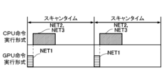
- the parallel instruction included in GPU instruction execution format 30 and corresponding to NET1 shown in FIG. 2A is included in CPU instruction execution format 32 and is started at the same time as the instruction corresponding to NET2, due to arbitration of the execution timing.
- each of the other NETs included in the sequence program 10 are also considered to be parallel instructions included in the GPU instruction execution format 30 and instructions included in the CPU instruction execution format 32, whose execution is started simultaneously.
- such instructions are considered to be parallel instructions included in the GPU instruction execution format 30, which are started after the execution of instructions included in the CPU instruction execution format 32.
- Fig. 8A is a flow chart showing the second command type determination process (S24) executed in place of the first command type determination process (S22) in the processing of the PLC programming device 2 shown in Fig. 7A.
- FIG. 8B is a diagram illustrating how parallel instructions included in GPU instruction execution format 30 and instructions included in CPU instruction execution format 32 are executed alternately by the process shown in FIG. 8A.
- FIG. 8C is a diagram illustrating the timing of execution of parallel instructions included in GPU instruction execution format 30 and instructions included in CPU instruction execution format 32, the execution timing of which is adjusted by the process shown in FIG. 8A.
- the extraction unit 202 determines whether the instructions included in the NET that was the subject of the process of S24 can be executed in parallel (S240).
- the extraction unit 202 determines whether the result of a parallel instruction included in another NET is input to the parallel instruction included in this NET, or the result of a sequential instruction included in another NET is input (S242).
- the extraction unit 202 determines that the parallel instruction included in this NET is a parallel instruction included in GPU processing 210 that is executed after GPU processing 220 that includes a sequential instruction that provides a result as input to this NET (S244).
- the extraction unit 202 When no results of instructions contained in other NETs are input to the instructions contained in this NET, or when the results of parallel instructions contained in other NETs are input (B), the extraction unit 202 includes the processing contained in this NET as a parallel instruction in the GPU processing 210 (S246).
- the extraction unit 202 determines whether the result of a parallel instruction or the result of a sequential instruction is input to the instructions included in this NET (S248).
- the extraction unit 202 includes the instructions included in this NET in the CPU processing 220 following the GPS processing 210 that includes a parallel instruction that provides a result as input to this NET (S250).
- the extraction unit 202 When the results of parallel instructions contained in another NET are input to an instruction contained in this NET, or when no results of instructions contained in another NET are input (D), the extraction unit 202 includes the instruction contained in this NET in the CPU processing 220 (S252).
- the PLC programming device 2 performs the processing of S202, S204, and S230 shown in FIG. 7A. As a result of this processing, the timing of execution of the parallel instructions included in the GPU instruction execution format 30 and the timing of execution of the sequential instructions included in the CPU instruction execution format 32 are arbitrated.
- the parallel instructions included in GPU instruction execution format 30 and the instructions included in CPU instruction execution format 32 are executed alternately during one scan time by arbitrating the execution timing of these instructions, as shown in FIG. 8B.
- the instruction included in GPU instruction execution format 30 and corresponding to NET2 shown in FIG. 2A becomes an instruction that is included in GPU instruction execution format 30 and starts after the parallel instruction corresponding to NET1 is completed.
- the instruction included in GPU instruction execution format 30 and corresponding to NET3 becomes a parallel instruction that starts after the execution of the instruction corresponding to NET2.
- each of the other NETs included in the sequence program 10 also become parallel instructions included in the GPU instruction execution format 30 that is started after execution of the CPU instruction execution format 32.
- the processes included in each of the other NETs included in the sequence program 10 also become instructions included in the CPU instruction execution format 32 that is started after execution of the GPU instruction execution format 30.
- the PLC programming device 2 can generate a sequence program execution format 3 from the sequence program 10 that is faster and has a shorter scan time.
- the processing by the PLC programming device according to the present disclosure may be realized by software.
- a program constituting this software is installed and executed on a user's computer.
- Such a program may be distributed to the user's computer by a removable medium and installed therein, or may be distributed to the user's computer from another computer via a network and installed therein.
- the program constituting this software does not necessarily have to be distributed to the user's computer, and may be provided to the user's computer as a Web service, for example.
- a PLC programming device (2) includes a program acquisition unit (200) that acquires a sequence program (10) to be executed by a PLC device (60), an extraction unit (202) that extracts, from the acquired sequence program (10), a sequential process (220) including sequential instructions to be executed sequentially and a parallel process (210) including parallel instructions that can be executed in parallel, a sequential process compilation unit (222) that compiles the extracted sequential process (220) into a sequential instruction execution format (32) executable by the PLC device (60), and a parallel process compilation unit (212) that compiles the extracted parallel process (210) into a parallel instruction execution format (30) executable by the PLC device (60).
- the extraction unit (202) extracts the sequential processing (220), or the sequential processing (220) and the parallel processing (210), based on a list of parallel executable instructions (204) indicating the parallel instructions.
- the PLC programming device (2) according to the present disclosure further includes an executable format input unit (500) that accepts an input in an executable format indicating that the sequence program (10) is to be executed in parallel, and the extraction unit (202) extracts the sequential processing (220) and the parallel processing (210) from the sequence program (10) when the executable format input unit (500) accepts an input indicating that the sequence program (10) is to be executed in parallel.
- the extraction unit (202) of the PLC programming device (2) acquires a portion (NET) of the accepted sequence program (10), analyzes the syntax of the acquired portion (NET) of the sequence program (10), and when it is determined as a result of the syntax analysis that the acquired portion (NET) of the sequence program (10) can be executed in parallel, it adds the acquired portion (NET) of the sequence program (10) to the parallel processing (210), and adds the acquired portion (NET) of the sequence program (10) to the sequential processing (220) except when it is determined that the acquired portion (NET) of the sequence program (10) can be executed in parallel.
- the extraction unit (202) of the PLC programming device (2) acquires a portion (NET) of the accepted sequence program (10), analyzes the syntax of the acquired portion (NET) of the sequence program (10), and as a result of the syntax analysis, the acquired portion (NET) of the sequence program (10) can be executed in parallel, and when the output of the sequential processing (220) is used, the acquired portion (NET) of the sequence program (10) is added to the parallel processing (210) which is processed after the sequential processing (220).
- the extraction unit (202) of the PLC programming device (2) of (Appendix 5) adds the acquired part (NET) of the sequence program (10) to the parallel processing (210) except when a part (NET) of the acquired sequence program (10) can be executed in parallel and the output of the parallel processing (220) is used or the output of the sequential processing (220) or the parallel processing (210) is used.
- the extraction unit (202) of the PLC programming device (2) acquires a portion (NET) of the accepted sequence program (10), performs syntax analysis of the acquired portion (NET) of the sequence program (10), and, except when the portion of the acquired sequence program (10) can be executed in parallel as a result of the syntax analysis, when the output of the parallel processing (210) is to be used, adds the acquired portion (NET) of the sequence program (10) to the sequential processing (220) which is processed after the parallel processing (210).
- the extraction unit (202) of the PLC programming device (2) of (Appendix 7) adds the acquired part of the sequence program (10) to the sequential processing (220) when using the output of the sequential processing (220) or the parallel processing (210) except when the acquired part (NET) of the sequence program (10) can be executed in parallel.
- the program according to the embodiment causes a computer to execute a program acquisition step (S100, S200) of acquiring a sequence program (10) to be executed by a PLC device (60), an extraction step (S22, S24) of extracting, from the acquired sequence program (10), a sequential processing step (220) including sequential instructions to be executed sequentially and a parallel processing step (210) including parallel instructions that can be executed in parallel, a sequential processing compilation step (S204) of compiling the extracted sequential processing (220) into a sequential instruction execution format executable by the PLC device (60), and a parallel processing compilation step (S202) of compiling the extracted parallel processing into a parallel instruction execution format executable by the PLC device (60).
Landscapes
- Engineering & Computer Science (AREA)
- General Engineering & Computer Science (AREA)
- Physics & Mathematics (AREA)
- General Physics & Mathematics (AREA)
- Theoretical Computer Science (AREA)
- Software Systems (AREA)
- Automation & Control Theory (AREA)
- Programmable Controllers (AREA)
Priority Applications (2)
| Application Number | Priority Date | Filing Date | Title |
|---|---|---|---|
| JP2025526921A JPWO2024257172A1 (https=) | 2023-06-12 | 2023-06-12 | |
| PCT/JP2023/021755 WO2024257172A1 (ja) | 2023-06-12 | 2023-06-12 | Plcプログラミング装置およびプログラム |
Applications Claiming Priority (1)
| Application Number | Priority Date | Filing Date | Title |
|---|---|---|---|
| PCT/JP2023/021755 WO2024257172A1 (ja) | 2023-06-12 | 2023-06-12 | Plcプログラミング装置およびプログラム |
Publications (1)
| Publication Number | Publication Date |
|---|---|
| WO2024257172A1 true WO2024257172A1 (ja) | 2024-12-19 |
Family
ID=93851460
Family Applications (1)
| Application Number | Title | Priority Date | Filing Date |
|---|---|---|---|
| PCT/JP2023/021755 Ceased WO2024257172A1 (ja) | 2023-06-12 | 2023-06-12 | Plcプログラミング装置およびプログラム |
Country Status (2)
| Country | Link |
|---|---|
| JP (1) | JPWO2024257172A1 (https=) |
| WO (1) | WO2024257172A1 (https=) |
Citations (4)
| Publication number | Priority date | Publication date | Assignee | Title |
|---|---|---|---|---|
| WO2017216858A1 (ja) * | 2016-06-14 | 2017-12-21 | 株式会社日立製作所 | 記録媒体、計算機、およびコード生成方法 |
| JP2019061466A (ja) * | 2017-09-26 | 2019-04-18 | オムロン株式会社 | 制御装置 |
| JP2019067045A (ja) * | 2017-09-29 | 2019-04-25 | オムロン株式会社 | 制御装置 |
| WO2020171234A1 (ja) * | 2019-02-22 | 2020-08-27 | 日本電信電話株式会社 | オフロードサーバのソフトウェア最適配置方法およびプログラム |
-
2023
- 2023-06-12 JP JP2025526921A patent/JPWO2024257172A1/ja active Pending
- 2023-06-12 WO PCT/JP2023/021755 patent/WO2024257172A1/ja not_active Ceased
Patent Citations (4)
| Publication number | Priority date | Publication date | Assignee | Title |
|---|---|---|---|---|
| WO2017216858A1 (ja) * | 2016-06-14 | 2017-12-21 | 株式会社日立製作所 | 記録媒体、計算機、およびコード生成方法 |
| JP2019061466A (ja) * | 2017-09-26 | 2019-04-18 | オムロン株式会社 | 制御装置 |
| JP2019067045A (ja) * | 2017-09-29 | 2019-04-25 | オムロン株式会社 | 制御装置 |
| WO2020171234A1 (ja) * | 2019-02-22 | 2020-08-27 | 日本電信電話株式会社 | オフロードサーバのソフトウェア最適配置方法およびプログラム |
Also Published As
| Publication number | Publication date |
|---|---|
| JPWO2024257172A1 (https=) | 2024-12-19 |
Similar Documents
| Publication | Publication Date | Title |
|---|---|---|
| US8645932B2 (en) | Control flow analysis methods and computing devices for converting COBOL-sourced programs to object-oriented program structures | |
| JP4822817B2 (ja) | コンパイルシステム | |
| CN103279418B (zh) | 一种组态控制信息的测试方法和装置 | |
| US20210096830A1 (en) | Incremental code generation method | |
| JPH05257709A (ja) | 並列化判別方法およびそれを用いた並列化支援方法 | |
| EP2850529A2 (en) | System and methods for generating and managing a virtual device | |
| CN110149800A (zh) | 一种用于处理与源程序的源代码相关联的抽象语法树的装置 | |
| CN106980597B (zh) | 片上系统验证方法及验证系统 | |
| US10884714B2 (en) | Method for modifying models for generating source code | |
| WO2020017264A1 (ja) | シミュレーション装置、及びその方法、並びにecu装置 | |
| US10884715B2 (en) | Method for generating source code | |
| JP2009009418A (ja) | 検証装置および検証方法 | |
| Consel | From a program family to a domain-specific language | |
| WO2024257172A1 (ja) | Plcプログラミング装置およびプログラム | |
| US6086624A (en) | Simulator and simulation method in each of which simulation can be carried out at a high-speed | |
| JPH05346332A (ja) | 試験プログラム実行方法 | |
| JP3840149B2 (ja) | コンパイラ、演算処理システム及び演算処理方法 | |
| Obster et al. | Development and execution of PLC programs on real-time capable mobile devices | |
| US20250165232A1 (en) | Method for generating source code | |
| JP2005174045A (ja) | ソースプログラム変換装置、ソースプログラム変換方法、ソースプログラム変換プログラム、および、プログラム記録媒体 | |
| CN112527574A (zh) | 一种处理器测试方法、装置、设备及可读存储介质 | |
| KR102301651B1 (ko) | 테스트 패턴 발생 장치 및 방법, 이를 이용한 테스트 시스템과, 컴퓨터 프로그램 | |
| KR102601979B1 (ko) | 소프트웨어 프로그램을 검증하는 방법 및 장치 | |
| US20250138784A1 (en) | Matrix calculation block and computer-implemented method for computer-aided generation of an executable control program | |
| JP7309099B2 (ja) | 等価性検査システムおよび等価性検査プログラム |
Legal Events
| Date | Code | Title | Description |
|---|---|---|---|
| 121 | Ep: the epo has been informed by wipo that ep was designated in this application |
Ref document number: 23941482 Country of ref document: EP Kind code of ref document: A1 |
|
| ENP | Entry into the national phase |
Ref document number: 2025526921 Country of ref document: JP Kind code of ref document: A |
|
| WWE | Wipo information: entry into national phase |
Ref document number: 2025526921 Country of ref document: JP |
|
| NENP | Non-entry into the national phase |
Ref country code: DE |