WO2024253025A1 - 通信装置、制御方法、及び、プログラム - Google Patents
通信装置、制御方法、及び、プログラム Download PDFInfo
- Publication number
- WO2024253025A1 WO2024253025A1 PCT/JP2024/019970 JP2024019970W WO2024253025A1 WO 2024253025 A1 WO2024253025 A1 WO 2024253025A1 JP 2024019970 W JP2024019970 W JP 2024019970W WO 2024253025 A1 WO2024253025 A1 WO 2024253025A1
- Authority
- WO
- WIPO (PCT)
- Prior art keywords
- communication device
- communication
- network
- link
- mld
- Prior art date
- Legal status (The legal status is an assumption and is not a legal conclusion. Google has not performed a legal analysis and makes no representation as to the accuracy of the status listed.)
- Ceased
Links
Images


Classifications
-
- H—ELECTRICITY
- H04—ELECTRIC COMMUNICATION TECHNIQUE
- H04W—WIRELESS COMMUNICATION NETWORKS
- H04W76/00—Connection management
- H04W76/10—Connection setup
- H04W76/15—Setup of multiple wireless link connections
-
- H—ELECTRICITY
- H04—ELECTRIC COMMUNICATION TECHNIQUE
- H04W—WIRELESS COMMUNICATION NETWORKS
- H04W48/00—Access restriction; Network selection; Access point selection
- H04W48/20—Selecting an access point
-
- H—ELECTRICITY
- H04—ELECTRIC COMMUNICATION TECHNIQUE
- H04W—WIRELESS COMMUNICATION NETWORKS
- H04W52/00—Power management, e.g. Transmission Power Control [TPC] or power classes
- H04W52/02—Power saving arrangements
- H04W52/0203—Power saving arrangements in the radio access network or backbone network of wireless communication networks
- H04W52/0206—Power saving arrangements in the radio access network or backbone network of wireless communication networks in access points, e.g. base stations
-
- H—ELECTRICITY
- H04—ELECTRIC COMMUNICATION TECHNIQUE
- H04W—WIRELESS COMMUNICATION NETWORKS
- H04W84/00—Network topologies
- H04W84/02—Hierarchically pre-organised networks, e.g. paging networks, cellular networks, WLAN [Wireless Local Area Network] or WLL [Wireless Local Loop]
- H04W84/10—Small scale networks; Flat hierarchical networks
- H04W84/12—WLAN [Wireless Local Area Networks]
-
- H—ELECTRICITY
- H04—ELECTRIC COMMUNICATION TECHNIQUE
- H04W—WIRELESS COMMUNICATION NETWORKS
- H04W88/00—Devices specially adapted for wireless communication networks, e.g. terminals, base stations or access point devices
- H04W88/02—Terminal devices
- H04W88/06—Terminal devices adapted for operation in multiple networks or having at least two operational modes, e.g. multi-mode terminals
-
- H—ELECTRICITY
- H04—ELECTRIC COMMUNICATION TECHNIQUE
- H04W—WIRELESS COMMUNICATION NETWORKS
- H04W88/00—Devices specially adapted for wireless communication networks, e.g. terminals, base stations or access point devices
- H04W88/08—Access point devices
- H04W88/10—Access point devices adapted for operation in multiple networks, e.g. multi-mode access points
-
- Y—GENERAL TAGGING OF NEW TECHNOLOGICAL DEVELOPMENTS; GENERAL TAGGING OF CROSS-SECTIONAL TECHNOLOGIES SPANNING OVER SEVERAL SECTIONS OF THE IPC; TECHNICAL SUBJECTS COVERED BY FORMER USPC CROSS-REFERENCE ART COLLECTIONS [XRACs] AND DIGESTS
- Y02—TECHNOLOGIES OR APPLICATIONS FOR MITIGATION OR ADAPTATION AGAINST CLIMATE CHANGE
- Y02D—CLIMATE CHANGE MITIGATION TECHNOLOGIES IN INFORMATION AND COMMUNICATION TECHNOLOGIES [ICT], I.E. INFORMATION AND COMMUNICATION TECHNOLOGIES AIMING AT THE REDUCTION OF THEIR OWN ENERGY USE
- Y02D30/00—Reducing energy consumption in communication networks
- Y02D30/70—Reducing energy consumption in communication networks in wireless communication networks
Definitions
- the present invention relates to a communication device for communicating data.
- the IEEE 802.11 standard series is known as the main communication standard for wireless LAN.
- the IEEE 802.11 standard series includes standards such as IEEE 802.11a/b/g/n/ac/ax.
- IEEE802.11be standard which is the successor to IEEE802.11ax, is currently being developed.
- a new function being considered for the IEEE802.11be standard is multi-link communication, in which an AP and a STA establish multiple links with different frequency channels and communicate in parallel.
- Patent Document 1 also describes a mechanism for establishing multiple links for multi-link communication.
- the EHT (Extreme High Throughput) TG is considering operating communication devices compatible with the IEEE802.11be standard in frequency bands such as 2.4 GHz, 4.9 and 5 GHz, and 6 GHz. TG stands for Task Group. Discussions have also begun on a successor standard to IEEE802.11be.
- the UHR (Ultra High Reliability) SG which is considering the successor standard, is focusing on the increased power consumption of access points in the successor standard as an issue, and is considering some kind of power-saving operation in the access points.
- an access point that performs multi-link communication realizes multi-link communication by having a multi-link upper MAC sublayer component comprehensively manage the lower sublayer.
- This lower sublayer is a combination of a component as a lower MAC sublayer and a PHY that corresponds one-to-one to the component.
- the access point has a non-multi-link upper MAC sublayer component so that it can communicate with an STA that supports only single-link communication, and can also realize single-link communication.
- the combination of the non-multi-link upper MAC sublayer and lower MAC sublayer components and the PHY associated with the components logically functions in the same way as a conventional access point.
- This single access point can also be considered an affiliated access point managed by the Multi-Link function, and is therefore also called an affiliated AP.
- the present invention has been made in consideration of at least one of the problems described above.
- One of the objectives of the present invention is to provide a mechanism for an access point to perform power-saving operation while suppressing problems in connection with Legacy STA in an environment that complies with old standards and where Legacy STAs are mixed.
- Another aspect of the present invention is to provide a mechanism for an access point to perform power-saving operation.
- a communication device provides an external device with a first network identified by a first BSSID (Basic Service Set Identifier) and a second network identified by a second BSSID, and is characterized in that, when the communication device uses a predetermined power saving mechanism and functions as a Multi-Link Device (MLD) that performs Multi-Link communication with another communication device, the communication device transmits a Beacon frame including the first BSSID on a channel that provides the first network, but has a communication control means that controls the communication device not to transmit a Beacon frame including the second BSSID on a channel that provides the second network.
- MLD Multi-Link Device
- an access point can perform power-saving operations while suppressing problems in connection with a Legacy STA.
- an access point can perform power-saving operations.
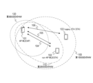
- FIG. 1 illustrates an example of a configuration of a communication system.
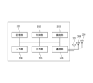
- a diagram showing an example of the hardware configuration of a communication device (AP MLD/non-AP MLD/Legacy STA).
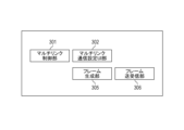
- a diagram showing an example of the functional configuration of a communication device (AP MLD/non-AP MLD).
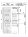
- FIG. 2 is a sequence diagram showing an example of Multi-Link communication in the present embodiment.
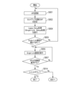
- 10 is a flowchart illustrating an example of notification control in the AP 101.
- 10 is a flowchart showing an example of connection control in the STA 102.
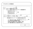
- FIG. 10 is a diagram showing an example of connection control in the STA 103. 13 is an example of a setting screen that the AP 101 provides to the user.
- the network according to this embodiment includes one access point device (hereinafter, also simply referred to as an AP, an AP STA, or an access point) and two station devices (hereinafter, also simply referred to as STAs, Non-AP STAs, or stations).
- AP access point
- AP STA access point
- STAs station devices
- Non-AP STAs stations
- AP101 and STA102 are configured to be able to communicate wireless frames that comply with the IEEE802.11bn standard, which is the successor to the IEEE802.11be standard and targets a maximum transmission speed of 46.08 Gbps.
- STA103 is a station device that supports a standard that precedes IEEE802.11be and does not support multi-link communication (e.g., IEEE802.11ac/n/g/b/a).
- IEEE is an abbreviation for the Institute of Electrical and Electronics Engineers. IEEE 802.11bn, the successor standard to IEEE 802.11be, has high reliability and low latency communication, and improved throughput during congestion as its main features. In addition, one of the goals of 802.11bn is to reduce power consumption in APs. Wireless frames communicated using this successor standard are also called UHR (Ultra High Reliability) PPDU.
- PPDU is an abbreviation for PLCP Protocol Data Unit
- PLCP is an abbreviation for Physical Layer Convergence Protocol.
- the name UHR was chosen for convenience, taking into account the goals to be achieved by the successor standard and the key features of the standard, and may be a different name once the standard has been fully developed.
- the name IEEE 802.11bn may be a different name once the standard has been fully developed.
- this specification and the appended claims are essentially applicable to all successor standards that are successors to the 802.11be standard.
- AP101 is an access point that supports a multi-band function that provides a network on multiple different frequency channels.
- the AP101 is an example of a tri-band access point that provides a 2.4 GHz band network (hereinafter also referred to as NW) 100, a 5 GHz band NW 110, and a 6 GHz band NW 120.
- NW100 provided by AP101 is a network that operates on any channel in the 2.4 GHz band, and the BSSID for identifying the network is a first BSSID.
- BSSID is an abbreviation for Basic Service Set Identifier
- BSS is an abbreviation for Basic Service Set.
- the NW110 provided by AP101 is a network that operates on any channel in the 5 GHz band, and the BSSID is a second BSSID.
- NW120 provided by AP101 is a network that operates on any channel in the 6 GHz band and has a third BSSID.
- NW100 is an example of a first network
- NW110 and 120 are examples of a second network.
- the AP 101 and STA 102 of this embodiment can establish multiple communication links between the devices and perform Multi-Link communication to communicate.
- the communication link is also simply called a link.
- the AP 101 that performs Multi-Link communication is also called an AP MLD (Multi-Link Device) 101
- the STA 102 that performs Multi-Link communication is also called a non-AP MLD 102.
- STA103 that supports only standards prior to 802.11ax and does not support standards subsequent to 802.11be, i.e., does not support the Multi-Link function, is also referred to as Legacy STA103 for convenience.
- AP 101 can establish link 104 in the 2.4 GHz band with STA 102 and communicate with it.
- AP 101 and STA 102 can also establish link 105 in the 5 GHz band, for example, and communicate with it.
- STA 102 executes Multi-Link communication in which it also communicates via link 105 in parallel with link 104.
- AP 101 can improve the throughput in communication with STA 102 by establishing links with STA 102 on multiple different frequency channels.
- Legacy STA 103 can establish, for example, a 2.4 GHz band link 106 with AP 101 and communicate with it. In this embodiment, establishing only one link between devices and communicating over that single established link is called Single-Link communication.
- FIG. 1 shows a communication system including one AP MLD 101 and two STAs (non-AP MLD 102, Legacy STA 103), but the number of these units may be greater than that shown.
- the AP MLD 101 and non-AP MLD 102 are described as supporting UHR PPDU communication (transmission and reception), they can also be configured to support PPDU communication of legacy standards that predate the UHR standard.
- the AP 101 and STA 102 can be configured to support the transmission and reception of PPDUs of IEEE 802.11a/b/g/n/ac/ax/be standards, etc.
- AP101 and STA102-103 are configured to be able to communicate in the 2.4 GHz, 5 GHz, and 6 GHz bands.
- the frequency bands used by AP101 and STA102-3 are not limited to these, and may use different frequency bands such as the Sub1 GHz band or the millimeter wave band.
- AP101 and STA102 can also communicate using bandwidths of 20 MHz, 40 MHz, 80 MHz, 160 MHz, 320 MHz, 540 MHz, and 640 MHz.
- the bandwidths used by each communication device are not limited to these.
- this embodiment illustrates a case where links 104 and 105 that perform multi-link communication are links of different frequency bands, but this is not limited to this.
- AP101 can also perform multi-link communication with STA102 using multiple links of the same frequency band and different channels.
- the AP 101 is configured to provide multiple networks of the same frequency band but different channels to the surrounding area. More specifically, multiple communication links for Multi-Link communication may be established between devices, with W52, 36ch in the 5 GHz band as the first link and W53, 60ch also in the 5 GHz band as the second link. Also, links of the same frequency band and links of different frequency bands may be mixed.
- the AP 101 and the STAs 102 and 103 can also be configured to support wireless communication based on other communication standards such as Bluetooth (registered trademark), NFC, and Bluetooth (registered trademark) LE (Low Energy).
- NFC is an abbreviation for Near Field Communication.
- the AP 101 and the STAs 102 can also be configured to support wired communication using an Ethernet (registered trademark) cable or wired communication using optical fiber.
- Specific examples of the AP 101 include, but are not limited to, a wireless LAN router and a personal computer (PC).
- the AP MLD 101 and the non-AP MLD 102 may also be information processing devices such as wireless chips that support the transmission and reception of UHR PPDUs.
- the wireless chips can be configured to perform various controls using hardware circuits inside the wireless chips.
- the wireless chip can be configured so that various processes are executed by the cooperation of processors such as ASIPs, memories, and hardware circuits inside the chip.
- ASIP stands for application-specific instruction set processor.
- STA102 and STA103 include, but are not limited to, cameras, tablets, smartphones, PCs, mobile phones, video cameras, and wearable devices such as smart glasses.
- the IEEE 802.11bn standard focuses on the problem of increased power consumption of access points, and some power saving operation in the access point is being considered.
- the AP MLD realizes multi-link communication by having the components of the multi-link upper MAC sublayer comprehensively manage the lower sublayer.
- This lower sublayer is realized by a combination of a component as the lower MAC sublayer and a PHY that corresponds one-to-one to the component.
- the AP MLD has a non-multi-link upper MAC sublayer component so that it can communicate with STAs that support only single-link communication.
- the combination of the components of the non-multi-link upper MAC sublayer and the lower MAC sublayer and the PHY associated with the components functions logically in the same way as a conventional access point.
- the combination of these components and PHY is used to realize Single-Link communication with Legacy STAs, etc.
- This single access point can also be considered an affiliated AP managed by the Multi-Link function, and is therefore also called an affiliated AP.
- a mechanism is provided for an access point to perform power saving operation while suppressing problems in connection with Legacy STA in an environment where Legacy STA is mixed. The specifics are explained below.
- ⁇ Hardware configuration of communication device> 2 shows an example of the hardware configuration of a communication device (AP MLD 101, non-AP MLD 102, Legacy STA 103).
- the communication device has, as an example of the hardware configuration, a storage unit 201, a control unit 202, a function unit 203, an input unit 204, an output unit 205, a communication unit 206, and antennas 207 to 209.
- the storage unit 201 is composed of ROM and/or RAM, and stores various information such as programs for performing various operations described below and communication parameters for wireless communication.
- RAM stands for Random Access Memory
- ROM Read Only Memory
- storage unit 201 may also use storage media such as non-volatile storage devices such as hard disks and SSDs (Solid State Drives).
- the control unit 202 is composed of, for example, a processor such as a CPU or MPU, an ASIC (Application Specific Integrated Circuit), a DSP (Digital Signal Processor), an FPGA (Field Programmable Gate Array), etc.
- CPU stands for Central Processing Unit
- MPU stands for Micro Processing Unit.
- the control unit 202 executes the programs stored in the memory unit 201 and controls the entire device by operating hardware circuits such as the ASIC.
- the control unit 202 may also control the entire device through cooperation between the programs stored in the memory unit 201 and an OS (Operating System).
- OS Operating System
- the control unit 202 also controls the functional unit 203 to perform predetermined processing such as imaging, printing, and projection.
- the functional unit 203 is hardware for the device to perform predetermined processing.
- the communication device is a camera such as a digital still camera or a smartphone having a camera
- the functional unit 203 is an imaging unit that performs imaging processing of surrounding images via a camera unit (not shown) that the communication device has.
- the functional unit 203 is a printing unit that performs printing processing on a sheet such as paper based on print data obtained from the outside via wireless communication.
- the functional unit 203 is a projection unit that performs projection processing of image data or video data obtained from the outside via wireless communication.
- the projection surface is the retina of the end user.
- the data processed by the functional unit 203 may be data stored in the storage unit 201, or may be data communicated with other APs or STAs via the communication unit 206 described later.
- communication devices such as AP101 can also provide network storage functions such as NAS (Network Attached Storage). This function is provided to other communication devices as a Web service such as a network storage service.
- NAS Network Attached Storage
- a communication device such as a STA connects to a network storage service provided by AP MLD101 or the like using a protocol such as SMB, FTP, or WebDAV.
- the communication device such as a STA then uploads files to the storage service and downloads files from the storage.
- the upload and download data communication is also realized by communicating UHR PPDU between devices.
- the input unit 204 receives various operations from the user.
- the output unit 205 outputs various types of data to the user.
- the output by the output unit 205 includes at least one of display on a screen, audio output by a speaker, and vibration output, for example.
- both the input unit 204 and the output unit 205 may be realized by a single module, such as a touch panel.
- the output unit 205 functions as a display unit that presents information to the user, and the input unit functions as a receiving unit that receives user operations.
- the communication unit 206 controls wireless communication conforming to the IEEE 802.11 standard series and IP communication.
- the communication unit 206 can cooperate with the antennas 207-209 to execute communication control for transmitting and receiving UHR PPDUs, which are wireless frames conforming to the UHR standard, and PPDUs conforming to earlier standards.
- the antennas 207-209 are antennas capable of transmitting and receiving signals in at least one of the frequency bands, for example, the sub-GHz band, the 2.4 GHz band, the 5 GHz band, the 6 GHz band, and the millimeter wave band.
- the communication unit 206 may be configured to control wireless communication and wired communication that comply with these communication standards.
- the communication units 206 of the AP MLD 101 and non-AP MLD 102 have hardware circuits that decode and encode signals communicated over each link. Each antenna and hardware circuit is configured to enable individual power control. It is also possible to configure the device to have a separate communication unit corresponding to each link.
- Communication devices such as the AP MLD 101 and non-AP MLD 102 have functional units such as a multi-link control unit 301, a multi-link communication setting UI unit 302, a frame generation unit 305, and a frame transmission/reception unit 306.
- the multi-link control unit 301 is a functional block that controls the communication start process for establishing one or more links used by a communication device for wireless communication with a partner device, the process for adding and deleting links after communication has started, and the communication end process for deleting all links.
- the connection process is composed of authentication process, association process, and 4-way handshake process.
- the partner device is an STA such as non-AP MLD 102
- the partner device is an AP such as AP MLD 101.
- the multi-link control unit 301 also controls the AP power saving mode. Specifically, when the AP power saving mode is enabled, it performs power control such as stopping the power supply to components that function as affiliated APs.
- the fact that the AP power saving mode is enabled means that the AP MLD 101 uses a specified power saving mechanism.
- the Multi-Link communication setting UI (User Interface) unit 302 provides a setting screen as a UI for the user to input settings related to Multi-Link communication.
- the UI unit 302 is also a functional block that accepts user operations on the setting screen via the input unit 204 and stores the settings in the memory unit 201 as operation settings of the communication device.
- the UI unit 302 of the AP MLD 101 can display the setting screen shown in FIG. 9 and accept setting changes from the user.
- FIG. 9 is an example of a setting screen that the UI unit 302 of the AP MLD 101 displays on the output unit 205.
- the display items in the area indicated by the dashed line are display items that are only displayed in the modified example described below. Therefore, a description of the first embodiment will be omitted.
- Display item 903 is a check box for setting whether AP power saving mode is enabled or disabled. The user can change whether AP power saving mode is enabled or disabled by operating this check box. After a change operation is performed, when it is detected that the user has selected the OK button, the UI unit 302 stores the operation setting corresponding to the change operation (setting to enable or disable AP power saving mode) in the storage unit 201.
- the operation setting is referred to as appropriate in the flowchart described below.
- the UI unit 302 of the AP MLD 101 also functions as an HTTP server, providing web content corresponding to the setting screen to the connected STA that it provides.
- the AP MLD 101 provides web content corresponding to the setting screen described in FIG. 9 to the connected STA.
- the STA displays the setting screen as a web screen based on the received web content.
- the STA transmits information specifying the operation content performed via the display items on the web screen to the HTTP server. The transmission can be performed using the POST method or the like.
- the UI unit 302 appropriately changes the operation settings stored in the memory unit 201 based on that information.
- the frame generation unit 305 is a block that generates UHR PPDUs, which are wireless frames for communicating with the outside world.
- the frame transmission/reception unit 306 transmits wireless frames generated by the frame generation unit 305 and receives wireless frames from the other device.
- the non-AP MLD 102 transmits Probe Request frames, Association Request frames, and data frames to the AP.
- the non-AP MLD 102 also transmits Authentication Request frames and other frames for connection processing to the AP.
- the AP MLD 101 transmits a beacon frame, a probe response frame, an association response frame, and a data frame to the STA 102.
- the AP MLD 101 also transmits an association request frame, an authentication request frame, and other frames for connection processing to the STA.
- Legacy STA 103 differs from non-AP MLD 102 in that it has a Single-Link control unit for establishing one link with an AP instead of multi-link control unit 301 and performs single-link communication.
- Legacy STA 103 is an STA that cannot perform multi-link communication, but supports single-link communication with affiliated APs.
- the AP MLD 101 illustrates a processing procedure when the AP power saving mode is set to be enabled.
- two states Active State and Power Saving State, are used.
- the Active State is a state in which all affiliated APs (Affiliated APs 1 to 3) are operated in an awake state.
- the Power Saving State is a state that aims to reduce power consumption per unit time compared to the Active State.
- the AP MLD 101 assumes that after transitioning to the Power Saving State, the power supply to the affiliated AP 2 and the affiliated AP 3 is limited to operate in a doze state to reduce power consumption.
- the affiliated AP 1 is operated in an awake state even after transitioning to the Power Saving State so that the Legacy STA can perform data communication without problems.
- Putting the affiliated APs 2 to 3 in a doze state specifically means stopping the power supply to the circuit for transmitting and receiving frames for the affiliated APs 2 to 3, and changing to a state in which frames are not transmitted or received.
- the Active State is an example of a first state, which is an operating state of a predetermined power saving mechanism.
- the Power Saving State is an example of a second state which is an operating state of a predetermined power saving mechanism.
- AP 101 periodically transmits a beacon 401 identified by the BSSID 1 described above.
- the beacon 401 of affiliated AP 1 is transmitted in non-HT (non-high-throughput) PPDU format so that the Legacy STA that receives the frame can decode the frame.
- the beacon frame 401 as a MAC (Medium Access Control) frame is periodically transmitted to the outside as a wireless frame in non-HT PPDU format.
- AP MLD 101 operates affiliated APs 2-3 in an awake state. However, it controls so as not to transmit the beacon of affiliated AP 2, i.e., the beacon identified by BSSID 2, and the beacon of affiliated AP 3, i.e., the beacon identified by BSSID 3.
- the non-AP MLD 102 which receives the beacon shown in 401, establishes multiple different links with the AP MLD 101 based on the Multi-Link Setup procedure described below (402). Information on other affiliated APs 2 and 3 that the AP MLD 101 is operating in an awake state is notified to the STA as appropriate using the Multi-Link Setup procedure, and is used to select links to be established as appropriate.
- the AP MLD 101 and non-AP MLD 102 are able to perform Multi-Link communication.
- the non-AP MLD 102 performs Multi-Link communication by simultaneously transmitting data using two communication links, or by using one link to transmit data while using another link to receive data.
- links 104 and 105 described in Figure 1 are established.
- Legacy STA103 executes the Legacy Setup procedure to establish Single-Link communication.
- beacons from affiliated AP2-3 are not transmitted. Therefore, when Legacy STA103 searches for APs that are candidates for connection, the search results show that affiliated AP1 is found, but affiliated AP2-3 are not found. Therefore, Legacy Setup is attempted for the found affiliated AP1, etc., to establish Single-Link communication.
- Affiliated AP1 and Legacy STA103 are able to perform Single-Link communication using one link.
- control is performed so that the beacon of an affiliated AP that may be in a doze state in the Power Saving State is not transmitted. Therefore, it is possible to prevent an affiliated AP that may be in a doze state from being captured by a Legacy STA.
- the AP MLD 101 judges whether the conditions for transitioning to the Power Saving State, such as the amount of data being communicated falling below a predetermined amount, are met. If it is determined that the conditions for transitioning to the Power Saving State are met, transition processing is performed to transition to the Power Saving State (404).
- the transition process involves power control that changes affiliated APs 2-3 to a doze state, and a Transition notification (405) that indicates a state transition for the non-AP MLD with which Multi-Link communication has been established.
- the non-AP MLD that receives the Transition notification performs power control on the STA side based on the notification.
- a case is illustrated in which non-AP MLD 102 puts affiliated STA 102 into a doze state and uses only link 104 as a data communication link.
- the flowchart in FIG. 5 shows an excerpt of the communication procedures that the AP MLD 101 executes with its peer STAs, such as the non-AP MLD 102 and the Legacy STA 103. Each process in FIG. 5 shows the processes that are executed after power is supplied to the AP MLD 101 and preparations for operation as an access point are complete.
- the flowchart in FIG. 6 shows an excerpt of the communication procedures that the non-AP MLD 102 executes with its peer APs, such as the AP MLD 101. Each process in FIG. 6 shows the processes that are executed after power is supplied to the non-AP MLD 102 and preparations for operation as an STA are complete.
- FIG. 5 Each process shown in the flowchart in FIG. 5 is executed by the processor of the control unit 202 of the AP MLD 101 executing a computer program stored in the storage unit 201. Note that some processes such as transmission and modulation are realized by the processor of the control unit 202 in cooperation with the various processors, ASICs, DSPs, and FPGAs that make up the communication unit 206, and the ASICs, DSPs, and FPGAs that make up the control unit 202. Note that when it is necessary to clearly indicate the subject of a process, the functional units described in FIG. 3 will be used as the subject in the explanation.
- control unit 301 determines whether or not an operational setting that enables the AP power saving mode has been configured. If an operational setting that enables the AP power saving mode has been configured, the control unit 301 advances the process to S502, and if an operational setting that enables the AP power saving mode has not been configured, the control unit 301 advances the process to S509.
- control unit 301 refers to the operation settings stored in the memory unit 201, and if an operation setting that enables the AP power saving mode is stored, it determines that the operation setting that enables the AP power saving mode has been set. On the other hand, the control unit 301 refers to the operation settings stored in the memory unit 201, and if an operation setting that disables the AP power saving mode is stored, it determines that the operation setting that enables the AP power saving mode has not been set.
- the control unit 301 determines whether the AP MLD 101 is operating in the Active State in the AP power saving mode. If the AP MLD 101 is operating in the Active State in the AP power saving mode, the control unit 301 advances the process to S503. On the other hand, if the AP MLD 101 is not operating in the Active State in the AP power saving mode (i.e., if it is operating in the Power Saving State), the control unit 301 advances the process to S505.
- the control unit 301 determines whether the power saving mode state should transition from the Active State to the Power Saving State. If it is determined that the power saving mode state should transition from the Active State to the Power Saving State, the process proceeds to S504. On the other hand, if it is determined that the power saving mode state should not transition from the Active State to the Power Saving State, the process proceeds to S508. Whether or not the transition should be made can be determined based on whether or not the conditions for transitioning to the Power Saving State, such as the amount of data being communicated falling below a predetermined amount, are met.
- control unit 301 cooperates with the frame generation unit 305 to generate a Transition notification frame for the non-AP MLD.
- the control unit 301 cooperates with the transmission/reception unit 306 and the communication unit 206 to transmit the generated Transition notification frame.
- the control unit 301 determines whether the power saving mode state should transition from the Power Saving State to the Active State. If it is determined that the power saving mode state should transition from the Power Saving State to the Active State, the process proceeds to S506. On the other hand, if it is determined that the power saving mode state should not transition from the Power Saving State to the Active State, the process proceeds to S507. Whether or not the transition should be made can be determined based on the occurrence status of data to be communicated, the passage of a predetermined time, etc.
- control unit 301 cooperates with the frame generation unit 305 to generate a Transition notification frame for the non-AP MLD.
- the control unit 301 cooperates with the transmission/reception unit 306 and the communication unit 206 to transmit the generated Transition notification frame.
- control unit 301 cooperates with each unit to control affiliated APs 1-2 to operate in a doze state, and affiliated AP 3 to operate in an awake state.
- the control unit 301 also cooperates with the generation unit 305, the transmission/reception unit 306, and the communication unit 206 to execute a process of periodically transmitting a beacon identified by BSSID1, which is the beacon of affiliated AP1, on the operating channel of affiliated AP1.
- a beacon of BSSID1 that identifies NW100 is periodically transmitted on the channel that provides NW100.
- the control unit 301 cooperates with each unit to control affiliated APs 1 to 3 to operate in an awake state. At this time, the control unit 301 cooperates with the generation unit 305, the transmission/reception unit 306, and the communication unit 206 to execute a process of periodically transmitting a beacon of affiliated AP 1 on the operating channel of affiliated AP 1. At this time, the control unit 301 controls affiliated APs 2 to 3 operating in an awake state not to transmit their beacons (the beacon identified by BSSID 2 and the beacon identified by BSSID 3).
- the control unit 301 cooperates with each unit to control affiliated APs 1 to 3 to operate in an awake state. At that time, the control unit 301 cooperates with the generation unit 305, the transmission/reception unit 306, and the communication unit 206 to execute a process of periodically transmitting each beacon. More specifically, the control unit 301 executes a process of periodically transmitting a beacon of affiliated AP 1 on the operating channel of affiliated AP 1, and a beacon of affiliated AP 2 on the operating channel of affiliated AP 2. Furthermore, the control unit 301 executes a process of periodically transmitting a beacon of affiliated AP 3 on the operating channel of affiliated AP 3.
- the AP MLD 101 determines whether or not to perform a shutdown. If it determines that a shutdown should be performed, it executes a shutdown process (not shown), terminates the series of processes, and transitions to a power-off state. On the other hand, if the AP MLD 101 does not determine that a shutdown should be performed, it advances the process to S501.
- the process of stopping periodic transmission of Beacon frames was exemplified, but the AP MLD 101 also controls so as not to respond to other frames for connection that may be transmitted from Legacy STAs. Specific control will be explained using Table 1.
- the AP MLD 101 with the AP power saving mode set to enabled, controls the transmission of frames shown in Table 1 differently for affiliated AP 1, which remains awake, and the other affiliated APs 2 to 3, which may transition to doze.
- the control can be performed as described in the representative example above. Furthermore, the AP MLD 101 with the AP power saving mode enabled controls so as not to respond with a Probe Response frame to a Probe Request frame to which affiliated APs 2-3 should respond. Furthermore, the AP MLD 101 with the AP power saving mode enabled controls so as not to respond with an Association Response frame to an Association Request frame addressed to affiliated APs 2-3.
- the above control can prevent affiliated APs 2-3 from being discovered by an active scan by a Legacy STA. It is also possible to prevent the Legacy STA from connecting to affiliated APs 2-3 based on the communication parameters input by the user to the Legacy STA. Note that the Association Request may be responded to with an Association Response frame that notifies that the Association was not successful. In this case, the AP MLD 101 may transmit an Association Response frame with a Status code other than Success.
- the above-described process enables the access point to perform power-saving operations while preventing problems in connecting with Legacy STAs in an environment where Legacy STAs are mixed.
- FIG. 6 Each process shown in the flowchart in FIG. 6 is executed by the processor of the control unit 202 of the non-AP MLD 102 executing a computer program stored in the storage unit 201. Note that some processes such as transmission and modulation are realized by the processor of the control unit 202 working in cooperation with the various processors, ASIC, DSP, and FPGA that make up the communication unit 206, and the ASIC, DSP, and FPGA that make up the control unit 202. Note that when it is necessary to clearly indicate the subject of a process, the functional unit explained in FIG. 3 will be used as the subject in the explanation.
- control unit 301 of the non-AP MLD 102 cooperates with the frame transmission/reception unit 306 and the communication unit 206 to search for surrounding APs.
- the search is performed by passive scanning or active scanning that transmits a probe request to the surroundings.
- control unit 301 determines the AP to be set up. This determination may be, for example, a process of listing multiple APs found in the search and having the user select the target, or a process of automatically determining an AP that has been connected to in the past and has good signal strength as the target.
- the control unit 301 determines whether or not to establish multi-link communication with the AP determined as the setup target. If the control unit 301 determines that multi-link communication is to be established with the AP determined as the setup target, the process proceeds to S608. On the other hand, if the control unit 301 determines that multi-link communication is not to be established with the AP determined as the setup target (i.e., if it determines that one link is to be established with the AP determined as the setup target), the process proceeds to S604.
- control unit 301 cooperates with each unit to execute Legacy Setup processing (in other words, Single-Link Setup processing).
- This processing corresponds to the Authentication processing, Association processing, and 4-way handshake processing using MAC frames that do not include Multi-Link Elements, which were performed in standards prior to IEEE802.11ax.
- control unit 301 determines whether single-link communication has been established. If single-link communication has been established, the process proceeds to S606. If single-link communication has not been established, the process proceeds to S601, where a search process and a determination process are performed for an AP to be newly set up.
- control unit 301 cooperates with each unit to execute single-link communication with the AP with which the connection has been established.
- the control unit 301 determines whether to terminate the connection with the AP. If it is determined that the connection with the AP should be terminated, the process proceeds to S614, and if it is determined that the connection with the AP should not be terminated, the process proceeds to S606 again to execute single-link communication.
- control unit 301 executes the multi-link setup process in cooperation with each unit and the AP MLD (e.g., AP MLD 101) which is the opposite device.
- AP MLD e.g., AP MLD 101
- FIG. 7 is a sequence diagram showing the Multi-Link Setup process by AP MLD 101 and non-AP MLD 102 and the subsequent communication procedures.
- AP MLD101 periodically transmits beacons for affiliated AP1.
- the affiliated AP 1 of the AP MLD 101 and the non-AP MLD 102 communicate a Probe Request and a Probe Response (S701, S702).
- the request may include a Multi-Link Element.
- STA102 and AP101 communicate an ML Probe Request (S703) and an ML Probe Response (S704) to obtain information about each link.
- the ML Probe Request is a Probe Request that includes a Complete Profile Request as a Multi-Link Element, which requests a Complete Profile. This frame exchange exchanges information about each link that can be used for Multi-Link communication, as well as other capability information related to Multi-Link communication.
- S703 and S704 are frame exchanges to obtain detailed link information that could not be obtained in the probe response. Therefore, if this is the second connection and parameters were exchanged during the previous connection, the frame exchanges in S703 and S704 can be omitted.
- the AP MLD 101 and non-AP MLD 102 carry out each authentication process to authenticate each other between the devices (S705).
- the non-AP MLD 102 then transmits an Association Request to the AP as a connection request (S706).
- the connection request transmitted here may be a Re-Association Request.
- the STA 102 includes in the Association Request information that identifies the link to which it wishes to establish multi-link communication.
- the multi-link element is used to notify the AP MLD 101 of the link ID that identifies the link to which it wishes to connect. More specifically, the link to which it is requesting connection establishment is indicated by storing multiple link IDs to which it wishes to connect in the per-STA profile of the multi-link element.
- the AP MLD 101 and the non-AP MLD 102 perform a four-way handshake to generate a key for encrypted communication (S708).
- the STA 102 and the AP 101 are ready to communicate data frames.
- AP MLD 101 and non-AP MLD 102 which are now in a state where they can communicate data frames, communicate application data such as video, moving images, and audio.
- the procedure described above allows a Multi-Link communication connection to be established between AP101 and STA102.
- control unit 301 determines whether or not multi-link communication has been established. If multi-link communication has been established, the process proceeds to S610, and if multi-link communication has not been established, the process proceeds to S601, where a search process and a determination process are performed for an AP to be newly set up.
- control unit 301 cooperates with each unit to perform multi-link communication with the AP MLD (e.g., AP MLD 101) with which a connection has been established.
- the operation mode during communication may be NSTR (Nonsimultaneous transmit and receive) Operation. It may also be STR (simultaneous transmit and receive operation).
- the operation mode during communication may also be EMLSR (enhanced multi-link single radio) operation. It may also be EMLMR (enhanced multi-link multi-radio) operation.
- the control unit 301 cooperates with each unit to determine whether a Transition notification has been received from the connected AP MLD (e.g., AP MLD 101). If a Transition notification has been received, the process proceeds to S612; if not, the process proceeds to S613. In S612, the control unit 301 cooperates with each unit to execute control corresponding to the Transition notification. For example, in the case of a notification related to a transition to the Power Saving State, some affiliated STAs are transitioned to a doze state. Also, for example, in the case of a notification related to a transition to the awake State, some affiliated STAs are transitioned to an awake state. It is desirable for the transition notification to be a frame in a format that can also be interpreted by non-AP MLD, which does not support the 802.11bn standard and supports the 802.11be standard, but this is not limited to this.
- a request to delete links or a request to add links may be sent to handle the case where some affiliated APs transition to the doze state. Specifically, when transitioning to the Power Saving State, a request to delete links for affiliated APs 2-3 is sent, and only the link for affiliated AP 1, which remains awake, can be used. Also, when transitioning to the Active State, a request to add links for affiliated APs 2-3 can be sent, and measures such as increasing the number of links can be taken. In this case, the AP MLD 101 may define a new control frame as appropriate for non-AP MLDs that support the 802.11bn standard and notify using that frame.
- control unit 301 determines whether to terminate the connection with the AP. If the control unit 301 determines to terminate the connection with the AP, it cooperates with each unit to send a Disassociation frame or Deauthentication frame to the AP, terminates the connection with the AP MLD, and proceeds to S614. On the other hand, if the control unit 301 does not determine to terminate the connection with the AP, it proceeds to S610 and performs further Multi-Link communication.
- the non-AP MLD 102 determines whether to perform a shutdown. If it determines to perform a shutdown, it executes a shutdown process (not shown), terminates the series of processes, and transitions to a power-off state. On the other hand, if the non-AP MLD 102 does not determine to perform a shutdown, it advances the process to S601.
- FIG. 8 is a flowchart showing an example of the control of Legacy STA 103.
- Each process shown in the flowchart of FIG. 8 is executed by the processor of the control unit 202 of Legacy STA 103 executing a computer program stored in the storage unit 201.
- S801 to S802 are search and decision controls similar to S601 to S602. Since Legacy STA 103 does not support the Multi-Link function, after the decision is made, the process proceeds to S804, which is a single-sink connection process, which is different from the process in FIG. 6.
- the Single-Link connection and communication processing in S804 to S808 is the same as the processing in S604 to S608.
- the shutdown processing in S814 is also the same as S614.
- the affiliated AP1 will also be discovered in the search performed by the Legacy STA103. Therefore, the Legacy STA103 can properly establish a Single-Link. In addition, the affiliated AP1 always operates in an awake state and does not transition to a doze state, so that unstable connections and communications can be avoided.
- the AP MLD 101 in which the AP power saving mode is set to be enabled is controlled not to transmit frames for connection to the affiliated APs 2 and 3 that may transition to the doze state.
- a new management frame that notifies, notifies, or responds to information for connection to STAs of IEEE802.11bn or later.
- This new management frame is a MAC frame to which a type and subtype different from the MAC frame defined before IEEE802.11be are assigned. This new management frame cannot be interpreted by STAs that do not support the IEEE802.11bn or later standards, and is discarded.
- beacons 2 and 3 Such new management frames that notify, notify, or respond to information for connection can be configured to be periodically transmitted, responded to, or notified in the affiliated APs 2 and 3 as well.
- the beacon is in a frame format having a preamble that can identify it as a PPDU compatible with IEEE802.11bn or a later standard, it may be configured to be periodically transmitted by the affiliated APs 2 and 3 as well.
- the beacon frame is a frame in which a beacon frame as a MAC frame is encapsulated in the payload of a PPDU in UHR PPDU format, it may be periodically transmitted by the affiliated APs 2 and 3 as well.
- the AP MLD 101 may periodically transmit a UHR PPDU that stores a beacon frame of BSSID2 on the channel of the NW 110, and may periodically transmit a UHR PPDU that stores a beacon frame of BSSID3 on the channel of the NW 120.
- the affiliated APs 2 and 3 can be configured to appropriately transmit frames that notify the outside of information regarding their presence.
- the AP MLD 101 may respond to the Probe Request or Association Request to which the affiliated APs 2 and 3 that may transition to the doze state should respond if a specific condition is satisfied.
- the AP MLD 101 may be configured to respond to the Probe Request or Association Request that includes a Multi-Link Element. Also, even if it is identified that the Probe Request or Association Request frame received from the STA that complies with the IEEE802.11bn or later standard is a frame, the AP MLD 101 may respond to the frame.
- the AP MLD 101 may be configured to transmit a frame indicating a period during which other affiliated APs are in an awake state or a doze state in the affiliated AP 1 that is always in an awake state.
- the frame is assigned a type and subtype different from the frame defined before IEEE802.11be.
- the non-AP MLD 102 may be configured to interpret the frame indicating the period and appropriately change its own power state, etc.
- the frame indicating the period can also be configured to be transmitted by the affiliated APs 2 and 3 that are in an awake state.
- the frame described in the third modification may be a frame having a preamble that can be identified as a PPDU corresponding to IEEE802.11bn or a later standard.
- this frame may be a type of frame that can only be decoded by STAs corresponding to IEEE802.11bn or later standards, and cannot be decoded by Legacy STAs.
- the frame described in the third modification may be transmitted periodically.
- the display item 904 is a pull-down list for allowing the user to select a network to be always active.
- the UI unit 302 displays options that list BSSID, SSID (Service Set Identifier), and the operating frequency band of the network as options of the pull-down list. The user can change the network to be always active by selecting one option from among multiple options displayed in the pull-down list.
- the control unit 301 of the AP MLD 101 determines the affiliated AP to be constantly activated based on the operation settings.
- information 905 that assists the user in making a selection may be presented. For example, if the user has an old handset (STA), information recommending the 2.4 GHz band may be displayed.
- STA old handset
- the AP MLD 101 uses the Multi-Link function.
- the operation setting using the Multi-Link function or the operation setting not using the Multi-Link function is switched based on a change operation on the display item 901 of the setting screen of FIG. 9.
- the UI unit 302 stores the corresponding operation setting in the storage unit 201.
- the AP MLD 101 performs the process described in the above-mentioned embodiment and modified example.
- the AP MLD 101 may simply operate as an access point that supports multiple bands.
- the user can be configured to select the network to be used for Multi-Link communication.
- the user can specify the network for which Multi-Link communication is permitted to be established by operating display item 902.
- the OK button is pressed after detecting a change operation on 903
- the UI unit 302 stores the corresponding operation settings in the storage unit 201.
- the AP MLD 101 changes the link information notified in the Multi-Link Setup process. For example, when networks corresponding to affiliated AP1 and affiliated AP2 are specified, the AP MLD 101 treats only affiliated AP1-2 as communication links that can establish a Multi-Link connection.
- the AP MLD 101 may be configured to have a color LED (Light Emitting Diode) or the like that indicates a status as the output unit 205.
- the AP MLD 101 may have different display modes of the color LED when operating in the Power Saving State and when operating in the Active State. When operating in the Active State, it is sufficient to display a green or white LED that is constantly lit. Also, when operating in the Power Saving State, it is sufficient to display a constant orange LED or a flashing LED.
- the present invention can also be realized by a process in which a program for implementing one or more of the functions of the above-described embodiments is supplied to a system or device via a network or a storage medium, and one or more processors in a computer of the system or device read and execute the program.
- the present invention can also be realized by a circuit (e.g., ASIC) that implements one or more of the functions.
Landscapes
- Engineering & Computer Science (AREA)
- Computer Networks & Wireless Communication (AREA)
- Signal Processing (AREA)
- Computer Security & Cryptography (AREA)
- Mobile Radio Communication Systems (AREA)
Abstract
Description
図1に、本実施形態のネットワークの構成例を示す。本実施形態のネットワークは、1台のアクセスポイント装置(以降、単にAP、AP STA、アクセスポイントとも呼ぶ)と、2台のステーション装置(以降単にSTA、Non-AP STA、ステーションとも呼ぶ)とを含んで構成される。
図2は、通信装置(AP MLD101、non-AP MLD102、Legacy STA103)のハードウェア構成例を示す。通信装置は、そのハードウェア構成の一例として、記憶部201、制御部202、機能部203、入力部204、出力部205、通信部206、及びアンテナ207~209を有する。
出力部205は、ユーザに情報を提示する表示手段として機能する。また入力部はユーザ操作を受け付ける受付手段として機能する。
続けて、第1の実施形態におけるMulti-Link通信の一例を図4のシーケンス図を用いて説明する。図4では、AP MLD101は、AP省電力モードが有効に設定されている場合の処理手順を例示している。本実施形態では、AP省電力モードにおいて、Active Stateと、Power Saving Stateの2つの状態を使い分ける。Active Stateは、全てのAffiliated AP(Affiliated AP1~3)をawake状態で動作させるStateである。また、Power Saving Stateは、Active Stateと比較し、単位時間当たりの消費電力を削減することを目的としたStateである。本実施形態のAP MLD101は、Power Saving Stateに遷移した後、Affiliated AP2とAffiliated AP3への電力供給を制限しdoze状態で動作させ、消費電力を削減することを想定している。一方、Legacy STAが問題なくデータ通信を行えるようにAffiliated AP1に関しては、Power Saving Stateに遷移した後もawake状態で動作させる。Affiliated AP2~3をdoze状態にするということは、具体的には、Affiliated AP2~3用のフレームを送受信するための回路への電力供給を停止し、フレームの送受信をしない状態に変更することを意味する。Active Stateは所定のパワーセービングメカニズムの動作ステートである第1ステートの一例である。また、Power Saving Stateは所定のパワーセービングメカニズムの動作ステートである第2ステートの一例である。

上述の実施形態では、AP省電力モードが有効に設定されたAP MLD101は、doze状態に遷移しうるAffiliated AP2、3においては接続のためのフレームを送信しないよう制御することを例示した。一方で、IEEE802.11bn以降のSTAに向けて接続のための情報を報知したり通知したり応答したりする新たなマネジメントフレームを設けることも考えられる。この新たなマネジメントフレームは、IEEE802.11be以前に定義されたMACフレームとは異なるタイプ、サブタイプが割り当てられたMACフレームである。この新たなマネジメントフレームはIEEE802.11bn以降の規格をサポートしないSTAでは解釈できず、読み捨てることになる。このような接続のための情報を報知したり通知したり応答したりする新たなマネジメントフレームについては、Affiliated AP2、3においても定期送信したり応答したり通知したりするように構成することができる。なお、IEEE802.11bnまたはそれより後の規格に対応したPPDUであることを識別できるプリアンブルを有するフレーム形式のBeaconであれば、Affiliated AP2、3においても定期的に送信するように構成してもよい。例えば、UHR PPDU形式のPPDUのペイロードに対してMACフレームとしてのBeaconフレームをカプセル化したフレームであれば、Affiliated AP2、3においても定期的に送信するようにしてもよい。この場合、AP MLD101は、BSSID2のBeaconフレームを格納したUHR PPDUをNW110のチャネル上で定期的に送信し、BSSID3のBeaconフレームを格納したUHR PPDUをNW120のチャネル上で定期的に送信してもよい。言い換えるとIEEE802.11bn規格をサポートしないSTAがデコードできないタイプのフレームならば、Affiliated AP2、3においてもその存在に関する情報を外部に通知するフレームを適宜送信するよう構成することができる。
さらに、AP MLD101は、doze状態に遷移しうるAffiliated AP2、3が応答すべきProbe RequestやAssociation Requestに対して特定条件を満たす場合は応答を行うようにしてもよい。具体的には、Multi-Link Elementを含むProbe RequestやAssociation Requestに対しては対応する応答を行うよう構成することもできる。また、IEEE802.11bn以降の規格に対応したSTAから受信したProbe RequestやAssociation Requestフレームであることが特定できた場合においても、当該フレームに応答を行うようにしてもよい。
さらに、AP MLD101は、常時awake状態のAffiliated AP1において、他のAffiliated APがawake状態またはdoze状態になる期間を示すフレームを送信するように構成してもよい。当該フレームは、IEEE802.11be以前に定義されたフレームとは異なるタイプ、サブタイプが割り当てられる。この場合、non-AP MLD102は、当該期間を示すフレームを解釈し、自身の電力状態等を適宜変更するように構成すればよい。なお、当該期間を示すフレームは、awake状態のAffiliated AP2、3においても送信するように構成することもできる。変形例3で説明したフレームは、IEEE802.11bnまたはそれより後の規格に対応したPPDUであることを識別できるプリアンブルを有するフレームであってもよい。さらに、このフレームはIEEE802.11bn以降の規格に対応したSTAのみが復号でき、Legacy STAは復号できないタイプのフレームであってもよい。また、変形例3で説明したフレームは、周期的に送信されてもよい。
第1の実施形態及び上述の変形例では、2.4GHz帯のネットワークを提供するAffiliated AP1が常時awake状態となる場合を例示したが、これに限定されない。例えば、それらの形態に加えて、ユーザや管理者が常時awake状態とするAffiliated APを設定できるように構成することもできる。図9を用いてこの変形例について説明する。表示アイテム904は、常時起動するネットワークをユーザに選択させるためのプルダウンリストである。UI部302は、当該プルダウンリストの選択肢として、BSSIDや、SSID(Service Set Identifier)、ネットワークの動作周波数帯等を列挙した選択肢を表示する。ユーザはプルダウンリストに表示される複数の選択肢の中から1つの選択肢を選択する操作を行うことで、常時起動するネットワークを変更する変更操作を行うことができる。
第1の実施形態及び上述の変形例ではAP MLD101において、Multi-Link機能を利用する場合を例示した。一方、それらの形態に加えてMulti-Link機能を利用するかどうかをユーザ操作によって選択できるように構成することもできる。この場合、図9の設定画面の表示アイテム901に対する変更操作に基づきMulti-Link機能を利用する動作設定、又は、Multi-Link機能を利用しない動作設定を切り替えるように構成する。UI部302は、901に対する変更操作を検知した後にOKボタンが押下された場合、対応する動作設定を記憶部201に記憶する。そして、AP MLD101は、Multi-Link機能を利用する動作設定がなされている場合に、上述の実施形態や変形例で説明した処理を行う。一方、AP MLD101は、Multi-Link機能を利用する動作設定がなされていない場合は、単なるマルチバンドをサポートするアクセスポイントとして動作すればよい。
AP MLD101は、出力部205としてステータスを示すカラーLED(Light Emitting Diode)などを有するように構成してもよい。この場合、AP MLD101は、Power Saving Stateで動作する場合と、Active Stateで動作する場合とで、当該カラーLEDの表示様態を異ならせてもよい。Active Stateで動作する場合、緑や白等を常時点灯表示すればよい。また、Power Saving Stateで動作する場合、オレンジで常時点灯表示したり、点滅表示等をしたりすればよい。
本発明は、上述の実施形態の1以上の機能を実現するプログラムを、ネットワーク又は記憶媒体を介してシステム又は装置に供給し、そのシステム又は装置のコンピュータにおける1つ以上のプロセッサがプログラムを読出し実行する処理でも実現可能である。また、1以上の機能を実現する回路(例えば、ASIC)によっても実現可能である。
102 non-AP MLD
103 Legacy STA
206 通信部
Claims (11)
- 第1のBSSID(Basic Service Set Identifier)で識別される第1のネットワーク及び、第2のBSSIDで識別される第2のネットワークを外部装置に対して提供する通信装置であって、
前記通信装置が所定のパワーセービングメカニズムを利用する場合であって、かつ、前記通信装置が他の1つの通信装置とMulti-Link通信を行うMulti-Link Device(MLD)として機能する場合、前記通信装置が前記第1のネットワークを提供しているチャネル上で前記第1のBSSIDを含むBeaconフレームを送信するが、前記通信装置が前記第2のネットワークを提供しているチャネル上では前記第2のBSSIDを含むBeaconフレームを送信しないよう制御する通信制御手段を有することを特徴とする通信装置。 - 前記通信装置はアクセスポイント装置であり、
前記所定のパワーセービングメカニズムでは、動作ステートとして第1ステートと、前記第1ステートと比較して消費電力が少ない第2ステートを有しており、
前記通信制御手段は、前記第2ステートでアクセスポイント装置が動作する場合であっても、前記第1のネットワークを提供しているチャネル上で前記第1のBSSIDを含むBeaconフレームを送信することを特徴とする請求項1に記載の通信装置。 - 前記通信制御手段は、前記通信装置が前記第2のネットワークを提供しているチャネル上では、Beaconフレームに加えて、Probe Responseフレーム及び又はAssociation Responseフレームも送信しないよう制御することを特徴とする請求項2に記載の通信装置。
- 前記第2ステートは、Multi-Link通信に用いることができる複数のAffiliated APのうちの一部のAffiliated APをdoze状態で動作させるステートであり、
前記通信制御手段は、更に、前記一部のAffiliated APがawake状態になる期間及び又はdoze状態になる期間を通知するフレームを前記通信装置が前記第1のネットワークを提供しているチャネル上で送信することを特徴とする請求項2又は3に記載の通信装置。 - 前記通信装置が所定のパワーセービングメカニズムを利用する場合において、Beaconフレームを送信すべきネットワークを選択する選択手段をさらに有し、
前記選択手段で選択されたネットワークが前記第1のネットワークであることを特徴とする請求項1乃至4のいずれか1項に記載の通信装置。 - 前記選択手段は、設定画面を介してなされたユーザ操作に基づいてBeaconフレームを送信すべきネットワークを選択することを特徴とする請求項5に記載の通信装置。
- 前記Beaconフレームは、タイプフィールドに対して00が設定され、サブタイプフィールドに対して1000が指定されたMAC(Medium Access Control)フレームであることを特徴とする請求項1乃至6のいずれか1項に記載の通信装置。
- 前記通信制御手段は、IEEE802.11bn規格をサポートしないステーション装置がデコードできないタイプのフレームであって、前記通信装置の存在に関する情報を外部に通知するフレームについては、前記通信装置が前記第2のネットワークを提供しているチャネル上においても送信するよう制御することを特徴とする請求項7に記載の通信装置。
- 第1のBSSID(Basic Service Set Identifier)で識別される第1のネットワーク及び、第2のBSSIDで識別される第2のネットワークを外部装置に対して提供する通信装置であって、
前記通信装置が所定のパワーセービングメカニズムを利用する場合であって、かつ、前記通信装置が他の1つの通信装置とMulti-Link通信を行うMulti-Link Device(MLD)として機能する場合、前記通信装置が前記第1のネットワークを提供しているチャネル上で前記第1のBSSIDを含むBeaconフレームを含むnon-HT PPDU形式の無線フレームを送信し、前記通信装置が前記第2のネットワークを提供しているチャネル上では前記第2のBSSIDを含むBeaconフレームを含むUHR PPDU形式の無線フレームを送信するよう制御する通信制御手段を有することを特徴とする通信装置。 - 第1のBSSIDで識別される第1のネットワーク及び、第2のBSSIDで識別される第2のネットワークを外部装置に対して提供する通信装置の制御方法であって、
前記通信装置が所定のパワーセービングメカニズムを利用する場合であって、かつ、前記通信装置が他の1つの通信装置とMulti-Link通信を行うMulti-Link Device(MLD)として機能する場合、前記通信装置が前記第1のネットワークを提供しているチャネル上で前記第1のBSSIDを含むBeaconフレームを送信するが、前記通信装置が前記第2のネットワークを提供しているチャネル上では前記第2のBSSIDを含むBeaconフレームを送信しないよう制御する通信制御工程と、を有することを特徴とする制御方法。 - 請求項10に記載の通信装置の制御方法をコンピュータに実行させるためのプログラム。
Priority Applications (3)
| Application Number | Priority Date | Filing Date | Title |
|---|---|---|---|
| CN202480037661.3A CN121336463A (zh) | 2023-06-08 | 2024-05-31 | 通信设备、控制方法和程序 |
| EP24819255.1A EP4727218A1 (en) | 2023-06-08 | 2024-05-31 | Communication device, control method, and program |
| KR1020257037242A KR20250168658A (ko) | 2023-06-08 | 2024-05-31 | 통신 장치, 제어 방법 및 프로그램 |
Applications Claiming Priority (2)
| Application Number | Priority Date | Filing Date | Title |
|---|---|---|---|
| JP2023095004A JP2024176459A (ja) | 2023-06-08 | 2023-06-08 | 通信装置、制御方法、及び、プログラム |
| JP2023-095004 | 2023-06-08 |
Publications (1)
| Publication Number | Publication Date |
|---|---|
| WO2024253025A1 true WO2024253025A1 (ja) | 2024-12-12 |
Family
ID=93795910
Family Applications (1)
| Application Number | Title | Priority Date | Filing Date |
|---|---|---|---|
| PCT/JP2024/019970 Ceased WO2024253025A1 (ja) | 2023-06-08 | 2024-05-31 | 通信装置、制御方法、及び、プログラム |
Country Status (6)
| Country | Link |
|---|---|
| EP (1) | EP4727218A1 (ja) |
| JP (1) | JP2024176459A (ja) |
| KR (1) | KR20250168658A (ja) |
| CN (1) | CN121336463A (ja) |
| TW (1) | TW202450351A (ja) |
| WO (1) | WO2024253025A1 (ja) |
Citations (3)
| Publication number | Priority date | Publication date | Assignee | Title |
|---|---|---|---|---|
| JP2021103805A (ja) | 2019-12-24 | 2021-07-15 | キヤノン株式会社 | 通信装置、通信方法、およびプログラム |
| JP2022061316A (ja) * | 2020-10-06 | 2022-04-18 | 株式会社東芝 | 無線通信装置及び無線通信方法 |
| JP2023095004A (ja) | 2021-12-24 | 2023-07-06 | トヨタ自動車株式会社 | データ管理システムおよび開示サーバ、ならびにそれらに用いられる方法およびプログラム |
-
2023
- 2023-06-08 JP JP2023095004A patent/JP2024176459A/ja active Pending
-
2024
- 2024-05-08 TW TW113116949A patent/TW202450351A/zh unknown
- 2024-05-31 WO PCT/JP2024/019970 patent/WO2024253025A1/ja not_active Ceased
- 2024-05-31 KR KR1020257037242A patent/KR20250168658A/ko active Pending
- 2024-05-31 CN CN202480037661.3A patent/CN121336463A/zh active Pending
- 2024-05-31 EP EP24819255.1A patent/EP4727218A1/en active Pending
Patent Citations (3)
| Publication number | Priority date | Publication date | Assignee | Title |
|---|---|---|---|---|
| JP2021103805A (ja) | 2019-12-24 | 2021-07-15 | キヤノン株式会社 | 通信装置、通信方法、およびプログラム |
| JP2022061316A (ja) * | 2020-10-06 | 2022-04-18 | 株式会社東芝 | 無線通信装置及び無線通信方法 |
| JP2023095004A (ja) | 2021-12-24 | 2023-07-06 | トヨタ自動車株式会社 | データ管理システムおよび開示サーバ、ならびにそれらに用いられる方法およびプログラム |
Non-Patent Citations (1)
| Title |
|---|
| GUOGANG HUANG (HUAWEI): "CR for Power Save of NSTR Mobile AP MLD", IEEE DRAFT; 11-22-0356-07-00BE-CR-FOR-POWER-SAVE-OF-NSTR-MOBILE-AP-MLD, IEEE-SA MENTOR, PISCATAWAY, NJ USA, vol. 802.11 EHT; 802.11be, no. 7, 14 April 2022 (2022-04-14), Piscataway, NJ USA, pages 1 - 12, XP068190100 * |
Also Published As
| Publication number | Publication date |
|---|---|
| KR20250168658A (ko) | 2025-12-02 |
| JP2024176459A (ja) | 2024-12-19 |
| CN121336463A (zh) | 2026-01-13 |
| EP4727218A1 (en) | 2026-04-15 |
| TW202450351A (zh) | 2024-12-16 |
Similar Documents
| Publication | Publication Date | Title |
|---|---|---|
| US11510263B2 (en) | Method for using legacy Wi-Fi and Wi-Fi P2P simultaneously | |
| US11792632B2 (en) | Communicating apparatus, communication method, and storage medium storing program | |
| US9699715B2 (en) | Discovery method and device in a wireless communication system | |
| US8577999B2 (en) | Method for WLAN network and device role activation | |
| US10820375B2 (en) | Method and apparatus for turning on Wi-Fi infrastructure using BLE interface in wireless communication system | |
| US20190050175A1 (en) | Communication apparatus and printer | |
| US11803340B2 (en) | Communication apparatus | |
| JP2025121925A (ja) | 通信装置、通信方法、およびプログラム | |
| US10708964B2 (en) | Method and device for forming application service platform session in wireless communication system | |
| US11611604B2 (en) | Method and apparatus for receiving streaming via transport protocol in wireless communication system | |
| US20180049013A1 (en) | Method and device for executing service discovery in wireless communication system | |
| CN104956765A (zh) | 通信装置、用于通信装置的控制方法和程序 | |
| CN119946761A (zh) | 电子装置、电子装置的控制方法、存储介质和计算机程序产品 | |
| JP2024176459A (ja) | 通信装置、制御方法、及び、プログラム | |
| US20260006666A1 (en) | Access point device, control method, and storage medium | |
| US20260046955A1 (en) | Communication apparatus, control method thereof, and storage medium | |
| US20260046946A1 (en) | Communication apparatus, control method thereof, and storage medium | |
| US20250373748A1 (en) | Information processing apparatus, control method, and storage medium that stores program | |
| EP4694550A1 (en) | Communication apparatus, control method thereof, program and storage medium | |
| US20250203684A1 (en) | Communication apparatus, control method for controlling communication apparatus, and storage medium | |
| US20260046101A1 (en) | Communication apparatus, control method thereof, and storage medium | |
| US20250203685A1 (en) | Communication apparatus and control method for controlling communication apparatus | |
| US20250203525A1 (en) | A communication apparatus, a control method for controlling a communication apparatus, and a storage medium | |
| KR20260044227A (ko) | 통신 장치, 스테이션 장치, 제어 방법, 및 기억 매체 | |
| KR20250125889A (ko) | 통신 디바이스, 그 제어 방법, 프로그램을 저장하는 컴퓨터 판독가능 저장 매체, 및 프로그램 |
Legal Events
| Date | Code | Title | Description |
|---|---|---|---|
| 121 | Ep: the epo has been informed by wipo that ep was designated in this application |
Ref document number: 24819255 Country of ref document: EP Kind code of ref document: A1 |
|
| ENP | Entry into the national phase |
Ref document number: 1020257037242 Country of ref document: KR Free format text: ST27 STATUS EVENT CODE: A-0-1-A10-A15-NAP-PA0105 (AS PROVIDED BY THE NATIONAL OFFICE) |
|
| WWE | Wipo information: entry into national phase |
Ref document number: KR1020257037242 Country of ref document: KR |
|
| WWE | Wipo information: entry into national phase |
Ref document number: 202547111488 Country of ref document: IN |
|
| REG | Reference to national code |
Ref country code: BR Ref legal event code: B01A Ref document number: 112025024885 Country of ref document: BR |
|
| WWP | Wipo information: published in national office |
Ref document number: 202547111488 Country of ref document: IN |
|
| WWE | Wipo information: entry into national phase |
Ref document number: 2024819255 Country of ref document: EP |
|
| NENP | Non-entry into the national phase |
Ref country code: DE |
|
| ENP | Entry into the national phase |
Ref document number: 2024819255 Country of ref document: EP Effective date: 20260108 |
|
| ENP | Entry into the national phase |
Ref document number: 2024819255 Country of ref document: EP Effective date: 20260108 |
|
| ENP | Entry into the national phase |
Ref document number: 2024819255 Country of ref document: EP Effective date: 20260108 |
|
| ENP | Entry into the national phase |
Ref document number: 2024819255 Country of ref document: EP Effective date: 20260108 |
|
| ENP | Entry into the national phase |
Ref document number: 2024819255 Country of ref document: EP Effective date: 20260108 |
|
| WWP | Wipo information: published in national office |
Ref document number: 2024819255 Country of ref document: EP |