WO2024252974A1 - 集計装置、設備稼働状況可視化システム、設備稼働状況可視化方法およびプログラム - Google Patents
集計装置、設備稼働状況可視化システム、設備稼働状況可視化方法およびプログラム Download PDFInfo
- Publication number
- WO2024252974A1 WO2024252974A1 PCT/JP2024/019456 JP2024019456W WO2024252974A1 WO 2024252974 A1 WO2024252974 A1 WO 2024252974A1 JP 2024019456 W JP2024019456 W JP 2024019456W WO 2024252974 A1 WO2024252974 A1 WO 2024252974A1
- Authority
- WO
- WIPO (PCT)
- Prior art keywords
- information
- work
- operation information
- operational
- tallying
- Prior art date
- Legal status (The legal status is an assumption and is not a legal conclusion. Google has not performed a legal analysis and makes no representation as to the accuracy of the status listed.)
- Ceased
Links
Images




Classifications
-
- G—PHYSICS
- G06—COMPUTING OR CALCULATING; COUNTING
- G06Q—INFORMATION AND COMMUNICATION TECHNOLOGY [ICT] SPECIALLY ADAPTED FOR ADMINISTRATIVE, COMMERCIAL, FINANCIAL, MANAGERIAL OR SUPERVISORY PURPOSES; SYSTEMS OR METHODS SPECIALLY ADAPTED FOR ADMINISTRATIVE, COMMERCIAL, FINANCIAL, MANAGERIAL OR SUPERVISORY PURPOSES, NOT OTHERWISE PROVIDED FOR
- G06Q50/00—Information and communication technology [ICT] specially adapted for implementation of business processes of specific business sectors, e.g. utilities or tourism
- G06Q50/04—Manufacturing
Definitions
- This disclosure relates to a data collection device, an equipment operation status visualization system, an equipment operation status visualization method, and a program.
- a production equipment operation status management system that automatically collects data, accumulates it in a database, and outputs aggregated data (Patent Document 1).
- workers record "start and end of work,” “breaks,” “planned stoppages,” “setup stoppages,” and “equipment abnormality stoppages” on a process control client connected to the production equipment, and accumulate the data in an operation log database.
- This production equipment operation status management system analyzes the accumulated data and outputs aggregated results such as the breakdown of the operation status entered for each operating hour, ratios, and failure rates for each piece of equipment as aggregated data.
- the information output is based on a predefined calculation method, making it difficult to perform multifaceted analysis of the calculated data by calculating it using different calculation methods.
- This disclosure has been made in consideration of the above-mentioned circumstances, and aims to provide a tabulation device, an equipment operation status visualization system, an equipment operation status visualization method, and a program that enable multifaceted analysis of the operation status of production equipment.
- the tallying device disclosed herein comprises a receiving means, an instruction means, a calculation means, and an output means.
- the receiving means receives operation information, work information, and duty information.
- the instruction means instructs a method of tallying the received operation information, work information, and duty information.
- the calculation means tallys up the operation information, work information, and duty information based on the tallying method instructed by the instruction means.
- the output means outputs the tallying results.
- the tallying device disclosed herein performs tallying processing based on the instructed tallying method and outputs the tallying results. This makes it possible to analyze the operating status of production equipment from multiple perspectives, making it easier to analyze areas for improvement. This can contribute to improving the productivity of production equipment.
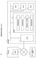
- FIG. 1 is a block diagram showing a functional configuration of a facility operation status visualization system according to an embodiment.
- FIG. 1 is a block diagram showing a physical configuration of a counting device according to an embodiment.
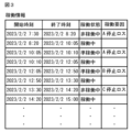
- FIG. 1 is a diagram showing a table of operation information stored in an equipment operation storage unit according to an embodiment;
- FIG. 1 is a diagram showing a table of operation information stored in an operation record storage unit according to an embodiment;
- FIG. 1 is a diagram showing a table of work information stored in a work system master storage unit according to an embodiment;
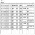
- FIG. 13 is a diagram showing a combined result table stored in an operation record storage unit according to an embodiment;
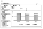
- FIG. 13 is a diagram showing an example of a display of a facility operation status graph displayed on a display unit according to an embodiment;
- FIG. 1 is a block diagram showing a physical configuration of a counting device according to an embodiment.
- FIG. 1 is a diagram showing a table of operation information stored in an equipment operation storage unit according to an embodiment;
- FIG. 13 is a diagram showing an example of a display of an equipment operation factor Pareto chart displayed on a display unit according to an embodiment
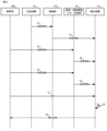
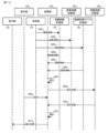
- FIG. 1 is a diagram showing a process performed by a facility operation status visualization system according to an embodiment.
- FIG. 2 is a diagram showing a process performed by the tallying device according to the embodiment;
- the facility operation status visualization system 1 comprises a compilation device 10 that collects and analyzes operation data from one or more production facilities 30 and outputs the analysis results, an operation/work information input/transmission unit 20, and a control unit 310 arranged in the production facilities 30, all of which are interconnected via a network NW.
- the production facilities 30 are not limited to industrial production facilities, but broadly include mining, manufacturing, agriculture, fisheries, transportation, and the like.
- the control unit 310 is originally a component of the production equipment 30 that produces and processes goods in a factory, and controls the operation of the entire or part of the production equipment 30. Alternatively, the control unit 310 may be dedicated to collecting and transmitting information. While controlling each part of the production equipment 30, the control unit 310 collects data on the operating status of the production equipment 30 and transmits it to the aggregation device 10 via the network NW.
- the control unit 310 includes, for example, a PLC (Programmable Logic Controller). Note that while only one production equipment 30 is illustrated in FIG. 1, typically multiple production equipment 30 are installed, and a control unit 310 is installed in each production equipment.
- control unit 310 sequentially acquires records of operation information of the production equipment 30 from the production equipment 30 and transmits them to the receiving unit 110 of the aggregation device 10.
- operation information refers to data including, for example, the operation status of the production equipment 30, operation factors indicating the factors that caused the transition to that operation status, and start and end times indicating the start and end points of the transition to the status related to the operation status and the operation factors, as exemplified in FIG. 3.
- the "operating state" of the operation information includes, for example, an operating state indicating that the production equipment 30 is operating, a semi-operating state indicating the stage preceding the operating state, and a non-operating state indicating that the production equipment 30 is stopped.
- the operating state refers to a state in which the production equipment 30 is engaged in operations such as producing, processing, or treating goods.
- the semi-operating state refers to a state in which the production equipment 30 is being started up, or is stopped for setup, in which preparatory operations necessary for operating the production equipment 30 are being carried out, in other words, preparation work is being carried out.
- the non-operating state refers to a state in which operation is stopped, such as when an abnormality occurs during the operation of the production equipment 30, causing it to stop.
- the "operation factor” indicates, for example, the reason why the operation state is semi-operating or not operating.
- the operation factor differs for each production facility. In this explanation, it is assumed that there are three factors: A stoppage loss, B stoppage loss, and C stoppage loss. For example, if forgetting to supply materials is cited as a cause of the operation state becoming semi-operating or not operating, the system administrator sets A stoppage loss to forgetting to supply materials, if a delay in the previous process is cited as a cause, the system administrator sets B stoppage loss to a delay in the previous process, and if a stoppage due to work setup is cited as a cause, the system administrator sets C stoppage loss to stoppage due to work setup. In this manner, the system administrator defines A stoppage loss, B stoppage loss, and C stoppage loss. If the operation state is operating, the operation factor is allowed to be left blank.
- the "start time” of the operation information indicates the time when the transition to a different operation state or operation factor begins when the operation state or operation factor transitions to a different operation state or operation factor.
- the “end time” of the operation information indicates the time when the operation state or operation factor prior to the transition ends when the operation state and operation factor transition to a different operation state or operation factor.
- control unit 310 When an operating state or operating factor transitions to a different operating state or operating factor, the control unit 310 acquires the new operating state, operating factor, and start time. When a transition occurs to a further different operating state and operating factor, the control unit 310 further acquires the end time.
- FIG. 3 illustrates an example of a table state in which operation information is accumulated.
- the control unit 310 is an example of a control means.
- the receiving unit 110 is an example of a receiving means.
- the operation/work information input transmission unit 20 shown in FIG. 1 is connected to the receiving unit 110 of the tabulation device 10 via the network NW.
- the operation/work information input transmission unit 20 transmits operation information and work information entered by the system administrator.
- the operation/work information input transmission unit 20 includes, for example, a computer.
- the system administrator inputs operation information of the facility where the production equipment 30 is installed, such as a company or factory, and work information of multiple workers who work on the production line where the production equipment 30 is located, into the operation/work information input/transmission unit 20.
- Operation means, for example, producing products using production equipment 30.
- the "operation information" includes an operation state and a start time and end time that indicate the start and end points of the transition to that operation state.
- FIG. 4 shows an example of a table in which the operation information is stored.
- the "operation status" of the operation information includes, for example, an operating status indicating that the operation is in progress, and a planned shutdown status indicating that the operation is undergoing a planned shutdown.
- the "start time” of the operation information indicates the time when operations will start if operations are in progress, and indicates the time when the planned shutdown of operations will start if operations are to be stopped.
- the “end time” indicates the time when operations will end, and the time when the planned shutdown will end.
- Work information is information related to the work of workers involved in production activities, and includes, as shown in FIG. 5, an employment form indicating the type of work, a time segment indicating the breakdown of working hours, a quasi-operation time, and a start time and end time indicating the start and end points of the transition to the employment form, the time segment, and the quasi-operation state.
- the "work type” in the work information indicates the type of work the worker does, and in this example includes information on whether it is a day shift or a night shift.
- the "time category” in the work information includes information on whether it is before work starts, during regular working hours, during overtime, during a break, or after work, for example.
- the "quasi-operation time" in the work information indicates the time period during which the production equipment 30 is in semi-operational status, for example, immediately after the start of work, immediately before a break, immediately after a break, immediately before the end of work at regular time, or immediately before the end of work.
- the quasi-operation time is allowed to be left blank.
- the "start time” of the work information indicates the time when the transition began when the working style, time segment, and quasi-working time transitioned to a different working style, time segment, and quasi-working time.
- the “end time” indicates the time when the working style, time segment, and quasi-working state ended.
- the operation/work information input/transmission unit 20 transmits the operation information and work information entered by the system administrator to the receiving unit 110 of the aggregation device 10.
- the operation/work information input transmission unit 20 may be configured to, for example, extract data for items corresponding to operation information from information input and processed in a facility management system that is prepared and operated separately from the equipment operation status visualization system 1, and transmit the data to the aggregation device 10.
- the operation/work information input transmission unit 20 may be configured to, for example, extract data for items corresponding to work information from information input and processed in a personnel system, payroll system, personnel management system, shift management system, etc. that are prepared and operated separately from the equipment operation status visualization system 1, and transmit the data to the aggregation device 10.
- the operation/work information input transmission unit 20 is an example of a transmission means.
- the tabulation device 10 shown in FIG. 1 is equipped with a computer, receives operation information sent from the control unit 310 of each production facility 30, and accumulates it as shown in FIG. 3, and receives operation information and work information sent from the operation/work information input transmission unit 20, and accumulates it as shown in FIG. 4 and FIG. 5.
- the tabulation device 10 integrates the accumulated operation information, operation information, and work information, and compiles an integrated result table as shown in FIG. 6, and further analyzes this in multiple analytical forms and outputs it.
- the aggregation device 10 includes a receiving unit 110 that receives data via the network NW, an instruction unit 120 that inputs instructions from the administrator 400, a calculation unit 130 that performs various calculation processes, a memory unit 140 that stores data, and a display unit 150 that displays data.
- the tallying device 10 has a central processing unit 11 that performs calculations and control, a main memory device 12 that temporarily stores the programs executed by the central processing unit 11, an auxiliary memory device 13 that stores the programs and other data, an input device 14 that accepts data and calculation instructions, a display device 15 that displays the results of the calculations, a communication module 16 connected to the network NW, and a bus line BL that electrically connects each device arranged in the tallying device 10.
- the central processing unit 11 executes the program to realize each function of the receiving unit 110, the instruction unit 120, the calculation unit 130, the memory unit 140, and the display unit 150 in Figure 1.
- the auxiliary memory device 13 is an example of a storage medium that stores a program that causes a computer to operate as the tallying device 10.
- the receiving unit 110 is connected to the control unit 310 and the operation/work information input transmission unit 20 of each production facility 30 via the network NW, and receives the operation information transmitted by the control unit 310 as well as the operation information and work information transmitted by the operation/work information input transmission unit 20.
- the memory unit 140 has an equipment operation memory unit 141, an operation record memory unit 142, a work system master memory unit 143, and an operation record memory unit 144.
- the equipment operation memory unit 141 accumulates and stores the operation information received by the receiving unit 110 in a table format as illustrated in FIG. 3.
- the operation record memory unit 142 accumulates and stores the operation information received by the receiving unit 110 in a table format as illustrated in FIG. 4.
- the work system master memory unit 143 accumulates and stores the work information received by the receiving unit 110 in a table format as illustrated in FIG. 5.
- the operation record memory unit 144 stores a combined result table, which will be described later with reference to FIG. 6, obtained by processing the received data.
- the memory unit 140 is an example of a storage means according to the present disclosure.
- the calculation unit 130 combines the operation information stored in the equipment operation memory unit 141, the operation information stored in the operation performance memory unit 142, and the work information stored in the work system master memory unit 143 using the start time and end time as keys.
- the calculation unit 130 is an example of a calculation means according to the present disclosure.
- the columns of the combined result table include start time, end time, operation status, working type, time segment, semi-operation time, operation status, and operation factor.
- the calculation unit 130 assigns an out-of-operation status, which indicates that the production facility 30 is not operating, to the field of the time period in which the operation status is neither in operation nor planned shutdown.
- the operation record storage unit 144 stores the combination result generated by the calculation unit 130 .
- the instruction unit 120 shown in FIG. 1 is operated by a system administrator or the like based on the interface displayed on the display unit 150, and instructs the calculation unit 130 on the method of aggregating the combined results stored in the operation performance storage unit 144.
- the display unit 150 displays various images, such as a user interface, and various charts obtained by tabulating the combined results shown in FIG. 6, under the control of the calculation unit 130.
- the display unit 150 is an example of a display means.
- the user interface has a field for selecting the format of the chart to be output, such as an equipment operation status graph or an equipment operation factor Pareto chart, as a selection item to be specified by the system administrator. Furthermore, each chart has fields for selecting and specifying the collection period, collection unit, working style, time segment, and quasi-operation time.
- a screen A1 shown in FIG. 7 is displayed on the display unit 150.
- the screen A1 includes a setting area A11 in which check boxes, buttons, etc. for selecting a calculation method are arranged, and a graph area A12 in which a chart is displayed.
- the graph area A12 displays an equipment operation status graph in which the horizontal axis indicates the daily, weekly, or monthly calculation unit and the vertical axis indicates the proportion of time for each operation status in a certain period.
- the equipment operation status graph shown in FIG. 7 shows that on February 1, of the time when the working style was day shift and the time categories were regular working hours and overtime, the operation status was operating for approximately 80% of the time, semi-operating for approximately 20% of the time, and non-operating for approximately 10% of the time.
- the aggregation period in the setting area A11 is an item for specifying the period to be aggregated based on the start time column and end time column in the combined result table.
- the aggregation unit indicates the unit period of aggregation, and is an item for specifying either the aggregation unit by day, by week, or by month, etc., based on the start time column and end time column in the combined result table.
- the work type is an item for specifying day shifts, night shifts, or both as the work type, based on the work type column in the combined result table.
- the time division is an item for specifying all or part of the items related to regular working hours, overtime, breaks, before the start of work, or after the end of work as time divisions, based on the time division column in the combined result table.
- the quasi-operating time is an item for specifying all or part of the items related to immediately after the start of work, immediately before a break, immediately after a break, immediately before the end of work, immediately before the end of work, as quasi-operating times, based on the quasi-operating time column in the combined result table. Each of these items is found by the calculation unit 130 selecting and processing the corresponding data in the integrated result table.
- the screen A2 shown in FIG. 8 is displayed on the display unit 150.
- the screen A2 includes a setting area A21 and a graph area A22.
- the graph area A22 displays an equipment operation factor Pareto chart with the horizontal axis representing operation factors and the vertical axis representing the total time.
- the equipment operation factor Pareto chart shown in FIG. 8 shows that on February 1, during the time when the working style was day shift and the time division was regular working hours and overtime, the time of A stoppage loss was approximately 30 minutes, the time of B stoppage loss was approximately 20 minutes, and the time of C stoppage loss was approximately 10 minutes. It can also be seen that A stoppage loss and B stoppage loss were in a semi-operating state, and C stoppage loss was not in operation.
- the functions of the items displayed in the setting area A21 namely the aggregation period, aggregation unit, working style, time division, and quasi-operation time, are the same as those of the items in the equipment operation status graph. Each of these items is also found by the calculation unit 130 selecting and processing the corresponding data in the integrated result table.
- the selection items that the system administrator should instruct from the instruction unit 120 are the collection period, collection unit, work type, time division, and quasi-operation time.
- the calculation unit 130 performs the necessary calculations on the necessary data according to the instructions from the instruction unit 120.
- the display unit 150 is an example of an output means according to the present disclosure.
- the instruction unit 120 is an example of an instruction means according to the present disclosure.
- the calculation unit 130 reads the aggregation method instructed by the system administrator from the instruction unit 120 and the combined results stored in the operation record storage unit 144, and aggregates the combined results based on the instructed aggregation method. For example, assume that the system administrator instructs the following aggregation method for the equipment operation status graph: 2022/02/01 to 2022/02/03 as the aggregation period, daily as the aggregation unit, day shift as the working style, regular working hours and overtime as the time division, and no semi-operation time is specified.
- the calculation unit 130 first extracts data from the combined results stored in the operation record storage unit 144, with a start time on or after 2022/02/01 and an end time on or before 2022/02/03, a working style of day shift, and a time division of regular working hours or overtime. Next, the extracted data is grouped into records with the same start and end dates, and the percentage of the operating status on the same date is calculated.
- the memory diagram 140 stores multiple sets of operation programs for the tallying and displaying processes executed by the calculation unit 130, such as the programs for the equipment operation factor Pareto chart creation process and display process described above with reference to FIG. 8, and fixed data. It is also configured to allow new programs to be installed.
- the display unit 150 reflects the results of the calculation unit 130 in an equipment operation status graph. For example, when the system administrator 400 instructs the calculation unit 130 to use the calculation method described above and the calculation unit 130 calculates the results based on that calculation method, the graph portion of FIG. 7 is output.
- the control unit 310 acquires operation information of the production facility 30 from the production facility 30 (step S1).
- the operation information acquired by the control unit 310 includes the operation state, operation factor, start time, and end time.
- the control unit 310 transmits the operation information acquired from the production equipment 30 to the receiving unit 110 of the aggregation device 10 (step S2).
- the operation information records to be transmitted may be transmitted one by one, or multiple records may be transmitted together.
- Steps S1 and S2 may be executed consecutively, or may be executed with a time interval.
- the system administrator 400 inputs the operation information of the production equipment 30 into the operation/work information input and transmission unit 20 (step S3).
- the operation information of the production equipment 30 input by the system administrator 400 includes the operation status, start time, and end time. Note that the administrator 400 or a person in charge of each department may input the operation information periodically or on a daily basis.
- the operation/work information input transmission unit 20 transmits the input operation information to the receiving unit 110 of the tabulation device 10 (step S4).
- the operation information records transmitted by the operation/work information input transmission unit 20 may be transmitted one by one, or multiple records may be transmitted together.
- Steps S3 and S4 may be executed consecutively, or may be executed with a time interval between them.
- the manager 400 or a person in charge of the operation management department may input the operation information periodically or on a daily basis.
- the system administrator 400 inputs the work information of multiple workers who work on the production line where the production equipment 30 is located into the operation/work information input transmission unit 20 (step S5).
- the work information includes the working style, time division, quasi-operation time, start time, and end time.
- the administrator 400 or a person in charge of human resources management may input the work information periodically or daily.
- the operation/work information input transmission unit 20 or the tabulation device 10 may also input part of the work information automatically. For example, by predefining 15 minutes after the start of work, 15 minutes before the end of work, 5 minutes before the break, and 5 minutes after the break as quasi-operation times, it is possible to reduce the labor required for input. Furthermore, quasi-operation times may be defined as 0 or blank, as necessary.
- the operation/work information input transmission unit 20 transmits the work information input by the system administrator 400 to the receiving unit 110 of the tabulation device 10 (step S6).
- the work information records transmitted by the operation/work information input transmission unit 20 may be transmitted one at a time, or multiple records may be transmitted together.
- Steps S5 and S6 may be executed consecutively or with a time interval between them. Furthermore, the execution timing of steps S1 and S2, the execution timing of steps S3 and S4, and the execution timing of steps S5 and S6 may be different from each other.
- the system administrator 400 transmits an instruction for the tallying method to the tallying device 10 (step S7).
- the tabulation device 10 tabulates the received operation information, production information, and work information (step S8).
- the system administrator 400 analyzes the tallying results that the tallying device 10 displays on the display unit 150 of the tallying device 10 (step S9).
- step S8 by the counting device 10 is shown in FIG. 10.
- the receiving unit 110 receives the operation information transmitted by the control unit 310 and the operation information and work information transmitted by the operation/work information input transmission unit 20.
- the equipment operation memory unit 141 stores the operation information received by the receiving unit 110 (step S801).
- the operation performance memory unit 142 stores the operation information received by the receiving unit 110 (step S802).
- the work system master storage unit 143 stores the work information received by the receiving unit 110 (step S803).
- the calculation unit 130 reads the operation information stored in the equipment operation memory unit 141 (step S804), reads the operation information stored in the operation performance memory unit 142 (step S805), and reads the work information stored in the work system master memory unit 143 (step S806).
- the calculation unit 130 combines the read operation information, work information, and shift information using the start time and end time as keys (step S807).
- the operation record storage unit 144 stores the combined results combined by the calculation unit 130 (step S808).
- the system administrator 400 causes the display unit 150 to display a screen that allows the user to select one of the tallying methods registered in the storage unit 140, and selects the desired tallying method. For example, the system administrator 400 selects tallying using the equipment operation status graph shown in FIG. 7 or tallying using the equipment operation factor Pareto chart shown in FIG. 8 on the selection screen, and further selects the items of tallying period, tallying unit, working style, time segment, and quasi-operation time. This makes it possible to specify the desired tallying method for the combined results stored in the operation performance storage unit 144.
- the calculation unit 130 reads the tallying method specified by the system administrator 400 from the instruction unit 120 (step S809).
- the calculation unit 130 reads the combination results stored in the operation performance storage unit 144 (step S810).
- the calculation unit 130 aggregates the combined results based on the aggregation method instructed by the system administrator 400 (step S811).
- the display unit 150 reflects the results of the calculation unit 130 in the equipment operation status graph or the equipment operation factor Pareto chart (step S812).
- the system administrator 400 identifies factors that reduce productivity in the production equipment 30 by analyzing the equipment operation status graph or equipment operation factor Pareto chart that reflects the tabulated results.
- the system administrator 400 can analyze the tabulated results from multiple angles by selecting whether or not to include in the productivity evaluation the periods when the operation status is semi-operating or non-operating that correspond to all or some of the semi-operating time items immediately after the start of work, immediately before a break, immediately after a break, immediately before the end of work on time, and immediately before the end of work, respectively. This makes it easier to identify factors that reduce productivity.
- the control unit 310 identifies that the production equipment 30 is in a semi-operating state and transmits the information to the aggregation device 10.
- the process of identifying the semi-operating state in the operation information can be complicated.
- the control unit 310 in order for the control unit 310 to identify that the production equipment 30 is in a semi-operating state, it is necessary to check the actual operation of the production equipment 30 one by one and set it in the control unit 310, which increases the amount of work required.
- the semi-operating state of the production equipment 30 is not used as an indicator for analyzing factors that reduce productivity, there is no need to perform such setting work.
- control unit 310 does not need to identify that the production equipment 30 is in a semi-operating state.
- the operation state of the operation information may be in a form that includes an operating state and a non-operating state, excluding the semi-operating state.
- the ID (identification information) of the production facilities 30 is assigned to the operation information, production information, and operation information and then sent to the aggregation device 10.
- the aggregation device 10 accumulates the received operation information, production information, and production information by ID.
- the aggregation device 10 generates combined results by ID.
- the aggregation device 10 may aggregate result information by ID according to instructions from the administrator 400, or may aggregate result information for multiple IDs together. With this configuration, it becomes possible to analyze the operation status of individual production facilities 30 and combinations of multiple production facilities 30.
- Equipment operation status visualization system 10 tallying device, 11 central processing unit, 12 main memory device, 13 auxiliary memory device, 14 input device, 15 display device, 16 communication module, 20 operation and work information input transmission unit, 30 production equipment, 110 receiving unit, 120 instruction unit, 130 calculation unit, 140 memory unit, 141 equipment operation memory unit, 142 operation performance memory unit, 143 work system master memory unit, 144 operation performance memory unit, 150 display unit, 310 control unit, 400 administrator, BL bus line, NW network.
Landscapes
- Business, Economics & Management (AREA)
- Engineering & Computer Science (AREA)
- Primary Health Care (AREA)
- Strategic Management (AREA)
- Economics (AREA)
- General Health & Medical Sciences (AREA)
- Human Resources & Organizations (AREA)
- Marketing (AREA)
- Manufacturing & Machinery (AREA)
- Health & Medical Sciences (AREA)
- Tourism & Hospitality (AREA)
- Physics & Mathematics (AREA)
- General Business, Economics & Management (AREA)
- General Physics & Mathematics (AREA)
- Theoretical Computer Science (AREA)
- General Factory Administration (AREA)
Abstract
集計装置は、受信手段と指示手段と演算手段と出力手段と、を備える。受信手段は、稼働情報、操業情報および勤務情報を受信する。指示手段は、受信した稼働情報、操業情報および勤務情報の集計方法を指示する。演算手段は、指示手段が指示した集計方法に基づいて稼働情報、操業情報および勤務情報を集計する。出力手段は、集計結果を出力する。
Description
本開示は集計装置、設備稼働状況可視化システム、設備稼働状況可視化方法およびプログラムに関する。
生産設備を伴う生産ラインにおいて、生産性を向上させるためには、生産性を低下させる要因を発見し、これを解消することが重要である。生産性を低下させる要因として、様々なものが考えられる。一例として、施設の休業に起因する設備の停止、設備の故障による停止、作業者による作業段取りによる設備の停止、材料供給忘れなど作業者の作業遅れによる設備の停止、前工程の遅れによる設備の停止などがある。これらの生産性低下要因を解消するには、生産設備の稼働状態を正確に把握し、改善を必要とする点、問題となっている点を解析する必要がある。ただし、解析に必要な情報は社内の様々な箇所に分散して保存されており、収集自体が困難なことが多い。
従来、このような生産設備の稼働状態の収集・分析は人手によって行われていた。例えば、生産設備が止まった際に、設備を扱う現場作業者が停止時間および停止要因を記録し、日報週報として生産管理部門に提出する方法がとられていた。このように人手で記録する場合、データの精度を担保することが難しい。また、収集したデータを解析用のツールに入力する際、再度転記作業が発生し、本来の生産業務以外の間接業務の負担が大きくなってしまう。
このような問題を解決するため、データを自動で収集してデータベースに蓄積し、集計データを出力する生産設備稼働状況管理システムが提案されている(特許文献1)。この生産設備稼働状況管理システムは、生産設備に接続されている工程制御クライアントにて、作業者が「始業終業」、「休憩」、「計画停止」、「段取り停止」、「設備異常停止」を記録し、稼働ログデータベースに蓄積する。この生産設備稼働状況管理システムは、蓄積したデータを解析し、集計データとして操業時間ごとの入力された稼働状況の内訳、比率、設備ごとの故障率などの集計結果を出力する。
特許文献1に開示された生産設備稼働状況管理システムでは、出力される情報は予め定められた集計方法に基づくものであるため、異なる集計方法で集計することにより集計データを多角的に分析することは困難である。
本開示は、上記実情に鑑みてなされたものであり、生産設備の稼働状況の多角的な分析を可能とする集計装置、設備稼働状況可視化システム、設備稼働状況可視化方法およびプログラムを提供することを目的とする。
上記の目的を達成するために、本開示にかかる集計装置は、受信手段と指示手段と演算手段と出力手段と、を備える。受信手段は、稼働情報、操業情報および勤務情報を受信する。指示手段は、受信した稼働情報、操業情報および勤務情報の集計方法を指示する。演算手段は、指示手段が指示した集計方法に基づいて稼働情報、操業情報および勤務情報を集計する。出力手段は、集計結果を出力する。
本開示にかかる集計装置は、指示されたる集計方法に基づいて集計処理を行い、集計結果を出力する。よって、複数の観点から、生産設備の稼働状況を分析することが可能となり、改善点の分析が容易となる。これにより、生産設備の生産性の向上に寄与できる。
以下、実施の形態にかかる集計装置、設備稼働状況可視化システム、設備稼働状況可視化方法および設備稼働状況可視化プログラムついて図面を参照しながら説明する。
図1に示すように、本実施の形態にかかる設備稼働状況可視化システム1は、1または複数の生産設備30の稼働データを収集して解析し、解析結果を出力する集計装置10と、操業・勤務情報入力送信部20と、生産設備30に配置された制御部310と、を備え、ネットワークNWを介して相互に接続されている。生産設備30は、工業の生産設備に限定されず、鉱工業、農業、水産業、運輸業などを広く含む。
制御部310は、本来的には、工場において物の生産、加工などを行う生産設備30の構成要素であり、生産設備30の全体または一部の動作を制御する。或いは、制御部310は、情報収集および送信専用でもよい。制御部310は、生産設備30の各部を制御しつつ、生産設備30の稼働状態に関するデータを収集し、ネットワークNWを介して集計装置10に送信する。制御部310は、例えば、PLC(Programmable Logic Controller)を備える。なお、図1では、生産設備30を1台のみ図示するが、通常、複数の生産設備30が配置され、各生産設備に制御部310が配置されている。
より詳細には、制御部310は、生産設備30の稼働情報のレコードを、該生産設備30から順次取得し、集計装置10の受信部110に送信する。本開示において、稼働情報は、図3に例示するように、例えば、生産設備30の稼働状態と、該稼働状態に遷移した要因を表す稼働要因と、該稼働状況および該稼働要因にかかるステータスに遷移した始点および終点を表す開始時刻および終了時刻と、を含むデータを指す。
稼働情報の「稼働状態」は、例えば、生産設備30が稼働していることを表す稼働中状態と、該稼働中状態の前段階であることを表す準稼働中状態と、生産設備30が停止していることを表す非稼働中状態と、を含む。稼働中状態とは、生産設備30が物の生産、加工、処理などの動作をしている状態を指す。準稼働中状態とは、生産設備30を立ち上げている状態、生産設備30の段取りのために停止をしている状態などの生産設備30を稼働させるために必要な準備動作をしている状態、すなわち準備作業中であることを指す。非稼働中状態とは、生産設備30の稼働中に異常が発生して停止した場合等、稼働を停止している状態を指す。
「稼働要因」は、例えば、稼働状態が準稼働中または非稼働中であることの原因を表す。稼働要因は、生産設備毎に異なる。この説明では、A停止ロスと、B停止ロスと、C停止ロスと、の3つの要因が存在するものとする。例えば、システムの管理者は、稼働状態が準稼働中または非稼働中になる原因として材料供給忘れが挙げられる場合にはA停止ロスに材料供給忘れを設定し、原因として前工程の遅れが挙げられる場合にはB停止ロスに前工程の遅れを設定し、原因として作業段取りによる停止が挙げられる場合にはC停止ロスに作業段取りによる停止を設定する、といった具合に、A停止ロスと、B停止ロスと、C停止ロスと、について定義付けを行う。稼働要因は、稼働状態が稼働中である場合には空白を許容する。
稼働情報の「開始時刻」は、稼働状態または稼働要因が、異なる稼働状態または稼働要因に遷移した場合に、該稼働状態または該稼働要因に遷移を開始した時刻を表す。稼働情報の「終了時刻」は、稼働状態および稼働要因が異なる稼働状態または稼働要因に遷移した場合に、遷移前の稼働状態または稼働要因が終了した時刻を表す。
稼働状態または稼働要因が異なる稼働状態または稼働要因に遷移した場合、制御部310は、遷移した新たな稼働状況と、稼働要因と、開始時刻と、を取得する。さらに異なる稼働状況および稼働要因に遷移した場合は、制御部310は、さらに終了時刻を取得する。
制御部310は、稼働情報のレコードを取得する度に、取得したレコードを集計装置10の受信部110に送信する。図3は、稼働情報を蓄積したテーブル状態を例示するものである。制御部310は、制御手段の一例である。受信部110は、受信手段の一例である。
図1に示す操業・勤務情報入力送信部20は、集計装置10の受信部110とネットワークNWを介して接続されている。操業・勤務情報入力送信部20は、システムの管理者により入力される操業情報および勤務情報を送信する。操業・勤務情報入力送信部20は、例えば、コンピュータを備える。
システムの管理者は、生産設備30が設置されている施設、例えば、会社、工場の操業情報と、生産設備30が配置された生産ラインにおいて作業をする複数の作業者の勤務情報と、を操業・勤務情報入力送信部20に入力する。
操業とは、例えば、生産設備30を用いて製品を生産することを意味する。
「操業情報」は、図4に例示するように、操業状態と、該操業状態に遷移した始点および終点を表す開始時刻および終了時刻と、を含む。図4は、操業情報が蓄積されたテーブルを例示する。
操業情報の「操業状態」は、例えば、操業中であることを表す操業中状態と、操業が計画停止中であることを表す計画停止中状態と、を含む。
操業情報の「開始時刻」は、操業する場合には、操業を開始する時刻を表し、操業を計画停止する場合には、操業の計画停止を開始する時刻を表す。「終了時刻」は、操業を終了する時刻、および、計画停止を終了する時刻を表す。
「勤務情報」は、生産活動に関わる作業者の勤務に係る情報であり、図5に例示するように、勤務の形態を示す就業形態と、勤務時間の内訳を表す時間区分と、準稼働時刻と、該就業形態、該時間区分および該準稼働状態に遷移した始点および終点を表す開始時刻および終了時刻と、を含む。
勤務情報の「就業形態」は、作業者の勤務の形態を示し、この例では、日勤か、夜勤か、の情報を含む。勤務情報の「時間区分」は、例えば、始業前か、定時内か、残業中か、休憩中か、終業後か、の情報を含む。
勤務情報の「準稼働時刻」は、例えば、生産設備30の稼働状態が準稼働中である時間帯を、始業直後か、休憩直前か、休憩直後か、定時終業直前か、終業直前か、の情報として表す。準稼働時刻は空白を許容する。
勤務情報の「開始時刻」は、就業形態、時間区分および準稼働時刻が異なる就業形態、時間区分および準稼働時刻に遷移した場合に、遷移を開始した時刻を表す。「終了時刻」は、就業形態、時間区分および準稼働状態が終了した時刻を表す。
操業・勤務情報入力送信部20は、システムの管理者が入力した操業情報および勤務情報を集計装置10の受信部110に送信する。
なお、操業・勤務情報入力送信部20に管理者が操業情報および勤務情報を入力する例を説明するが、これに限られない。操業・勤務情報入力送信部20は、例えば、設備稼働状況可視化システム1とは別に用意および運用されている施設管理システムで入力および処理されている情報のなかから操業情報に該当する項目のデータを抽出し、集計装置10に送信する構成でもよい。同様に、操業・勤務情報入力送信部20は、例えば、設備稼働状況可視化システム1とは別に用意および運用されている人事システム、給与計算システム、人員管理システム、シフト管理システム等で入力および処理されている情報のなかから勤務情報に該当する項目のデータを抽出し、集計装置10に送信する構成でもよい。操業・勤務情報入力送信部20は送信手段の一例である。
図1に示す集計装置10は、コンピュータを備え、各生産設備30の制御部310から送信されてくる稼働情報を受信して、図3に例示するように蓄積し、操業・勤務情報入力送信部20から送信されてくる操業情報と勤務情報を受信して、図4、図5に例示するように蓄積する。集計装置10は、蓄積した稼働情報、操業情報、勤務情報を統合して、図6に例示する統合結果テーブルを集計し、さらに、これを複数の解析形態で解析し、出力する。
集計装置10は、ネットワークNWを介してデータを受信する受信部110、管理者400の指示を入力する指示部120、各種演算処理を行う演算部130、データを記憶する記憶部140、データを表示する表示部150を備える。
集計装置10の物理的構成を図2に示す。図示するように、集計装置10は、演算および制御を行う中央処理装置11と、中央処理装置11が実行するプログラムを一時的に記憶する主記憶装置12と、該プログラムその他のデータを記憶する補助記憶装置13と、データおよび演算の指示を受け付ける入力機器14と、演算の結果を表示する表示機器15と、ネットワークNWに接続された通信モジュール16と、集計装置10に配置された各機器を電気的に接続するバスラインBLと、を有する。中央処理装置11がプログラムを実行することにより、図1における受信部110、指示部120、演算部130、記憶部140、表示部150、の各機能が実現される。なお、補助記憶装置13は、コンピュータに集計装置10としての動作を実行させるプログラムを記憶する記憶媒体の一例である。
受信部110は、各生産設備30の制御部310および操業・勤務情報入力送信部20にネットワークNWを介して接続され、該制御部310が送信した稼働情報ならびに操業・勤務情報入力送信部20が送信した操業情報および勤務情報を受信する。
記憶部140は、設備稼働記憶部141と、操業実績記憶部142と、勤務体制マスタ記憶部143と、稼働実績記憶部144と、を有する。設備稼働記憶部141は、受信部110が受信した稼働情報を図3に例示するようにテーブル状に蓄積して記憶する。操業実績記憶部142は、受信部110が受信した操業情報を図4に例示するようにテーブル状に蓄積して記憶する。勤務体制マスタ記憶部143は、受信部110が受信した勤務情報を図5に例示するようにテーブル状に蓄積して記憶する。稼働実績記憶部144は、受信データを加工して得られる図6を参照して後述する結合結果テーブルを記憶する。記憶部140は本開示にかかる記憶手段の一例である。
演算部130は、設備稼働記憶部141に記憶された稼働情報と、操業実績記憶部142に記憶された操業情報と、勤務体制マスタ記憶部143に記憶された勤務情報とを、開始時刻および終了時刻をキーとして結合する。演算部130は本開示にかかる演算手段の一例である。
演算部130が生成する結合結果テーブルの一例を図6に示す。結合結果テーブルのカラムは、開始時刻と、終了時刻と、操業状態と、就業形態と、時間区分と、準稼働時刻と、稼働状態と、稼働要因と、を含む。演算部130は、操業状態のカラムにおいて、操業状態が操業中状態または計画停止中状態のいずれの状態にもない時間帯のフィールドには、生産設備30が操業時間外であることを表す操業時間外状態を割り当てる。
稼働実績記憶部144は、演算部130が生成した結合結果を記憶する。
稼働実績記憶部144は、演算部130が生成した結合結果を記憶する。
図1に示す指示部120は、表示部150に表示されるインターフェースに基づいて、システムの管理者等により操作され、稼働実績記憶部144に記憶された結合結果の集計方法を演算部130に対して指示する。
表示部150は、演算部130の制御に従って、様々な画像、例えば、ユーザインタフェース、図6に示す結合結果を、集計処理して得られた様々な図表を表示する。表示部150は、表示手段の一例である。
ユーザインタフェースは、システムの管理者が指示すべき選択項目として、出力すべき図表の形態、例えば、設備稼働状態グラフ、設備稼働要因パレート図、等を選択する欄を有する。さらに、各図表には、集計期間と集計単位と就業形態と時間区分と準稼働時刻を選択指定する欄が配置される。
より詳細には、設備稼働状態グラフを表示部150に表示させる場合、図7に示す画面A1が表示部150に表示される。画面A1は、集計方法を選択可能なチェックボックス、ボタン等が配置されている設定領域A11と、図表が表示されるグラフ領域A12とを含む。グラフ領域A12では、横軸を日ごと、週ごとまたは月ごとの集計単位とし、縦軸を一定期間における稼働状態ごとの時間の割合とした、設備稼働状態グラフが表示される。例えば、図7に示す設備稼働状態グラフで、2月1日は、就業形態が日勤、時間区分が定時内及び残業中である時間のうち、稼働状態が稼働中である時間が約80%、準稼働中である時間が約20%、非稼働中である時間が約10%であったことが分かる。
設定領域A11における集計期間は、結合結果テーブルにおける開始時刻のカラムおよび終了時刻のカラムに基づいて、集計対象とする期間を指示するための項目である。集計単位は、集計の単位期間を示し、結合結果テーブルにおける開始時刻のカラムおよび終了時刻のカラムに基づいて、日ごと、週ごとまたは月ごと等のいずれかの集計単位を指示するための項目である。就業形態は、結合結果テーブルにおける就業形態のカラムに基づいて、日勤または夜勤もしくはその両方を就業形態として指示するための項目である。時間区分は、結合結果テーブルにおける時間区分のカラムに基づいて、定時内、残業中、休憩中、始業前または終業後にかかる項目の全部または一部を時間区分として指示するための項目である。準稼働時刻は、結合結果テーブルにおける準稼働時刻のカラムに基づいて、始業直後、休憩直前、休憩直後、定時終業直前、終業直前にかかる項目の全部または一部を準稼働時刻として指示するための項目である。これらの各項目は、演算部130が統合結果テーブル上の該当するデータを選択して処理することにより、求められる。
また、設備稼働要因パレート図を表示部150に表示させる場合、図8に示す画面A2が表示部150に表示される。画面A2は、設定領域A21と、グラフ領域A22とを含む。グラフ領域A22では、横軸を稼働要因とし、縦軸を時間の合計とした、設備稼働要因パレート図が表示される。例えば、図8に示す設備稼働要因パレート図で、2月1日は、就業形態が日勤、時間区分が定時内及び残業中である時間のうち、A停止ロスの時間は約30分、B停止ロスの時間は約20分、C停止ロスの時間は約10分であったことが分かる。また、A停止ロス及びB停止ロスは準稼働中状態、C停止ロスは非稼働中であったことが分かる。
設定領域A21に表示される集計期間と、集計単位と、就業形態と、時間区分と、準稼働時刻の各項目の機能は、設備稼働状態グラフにおける各項目の機能と同様である。これらの各項目も、演算部130が統合結果テーブル上の該当するデータを選択して処理することにより、求められる。
システムの管理者が指示部120から指示すべき選択項目としては、集計期間と、集計単位と、就業形態と、時間区分と、準稼働時刻と、である。演算部130は指示部120からの指示に従って必要なデータに必要な演算を行う。表示部150は本開示にかかる出力手段の一例である。指示部120は本開示にかかる指示手段の一例である。
演算部130は、システムの管理者が指示部120から指示した集計方法と、稼働実績記憶部144に記憶された結合結果と、を読み込み、指示された集計方法に基づいて、結合結果を集計する。例えば、設備稼働状態グラフにおいてシステムの管理者が集計期間として2022/02/01から2022/02/03まで、集計単位として日ごと、就業形態として日勤、時間区分として定時内および残業中、準稼働時刻は指定しない、という集計方法を指示したと仮定する。この場合は、まず、演算部130は、稼働実績記憶部144に記憶された結合結果から、開始時刻が2022/02/01以降で、終了時刻が2022/02/03以前で、就業形態が日勤で、時間区分が定時内または残業中であるデータを抽出する。次に、抽出したデータを開始時刻および終了時刻の年月日が同一であるレコードを纏め、同一の年月日における稼動状態の割合を算出する。
記憶図140には、演算部130が実行する集計処理と表示処理の動作プログラム、例えば、図8を参照して前述した設備稼働要因パレート図作成処理と表示処理のプログラムと固定データが複数セット記憶されている。また、プログラムを新たにインストールすることも可能に構成されている。
表示部150は、演算部130が集計した集計結果を設備稼働状態グラフに反映する。例えば、システムの管理者400が前記のような集計方法の指示をし、演算部130が該集計方法に基づいて集計した場合、図7のグラフ部分が出力される。
以下、図9を参照して、設備稼働状況可視化システム1による処理を説明する。
各生産設備30の制御部310は、稼働状態または稼働要因が異なる稼働状態または稼働要因に遷移した場合、生産設備30の稼働情報を生産設備30から取得する(ステップS1)。制御部310が取得する稼働情報は、稼働状態と、稼働要因と、開始時刻と、終了時刻と、を含む。
制御部310は、生産設備30から取得した稼働情報を集計装置10の受信部110に送信する(ステップS2)。送信する稼働情報のレコードは、1件ずつ送信されてもよく、複数件まとめて送信されてもよい。ステップS1とS2は、連続して実行されても、時間を置いて実行されてもよい。
システムの管理者400は、生産設備30の操業情報を操業・勤務情報入力送信部20に入力する(ステップS3)。システムの管理者400が入力する生産設備30の操業情報は、操業状態と、開始時刻と、終了時刻と、を含む。なお、管理者400または各部門の担当者等が、定期的或いは日常的に操業情報を入力してもよい。
操業・勤務情報入力送信部20は、入力された操業情報を集計装置10の受信部110に送信する(ステップS4)。操業・勤務情報入力送信部20が送信する操業情報のレコードは、1件ずつ送信されてもよく、複数件にまとめて送信されてもよい。なお、ステップS3とS4は、連続して実行されても、時間を置いて実行されてもよい。また、管理者400または操業管理部門の担当者等が、定期的或いは日常的に操業情報を入力してもよい。
システムの管理者400は、生産設備30が配置された生産ラインにおいて作業をする複数の作業者の勤務情報を操業・勤務情報入力送信部20に入力する(ステップS5)。勤務情報は、就業形態と、時間区分と、準稼働時刻と、開始時刻と、終了時刻と、を含む。なお、管理者400または人事管理部門の担当者等が、定期的或いは日常的に勤務情報を入力してもよい。また、操業・勤務情報入力送信部20または集計装置10が、勤務情報の一部を自動的に入力してもよい。例えば、始業後の15分間、終業前の15分間、休憩前の5分間、休憩後の5分間を準稼働時刻として予め定義することにより、入力作業を省力化することが出来る。また、必要に応じて、準稼働時刻を0または空白と定義してもよい。
操業・勤務情報入力送信部20は、システムの管理者400が入力した勤務情報を集計装置10の受信部110に送信する(ステップS6)。操業・勤務情報入力送信部20が送信する勤務情報のレコードは、1件ずつ送信されてもよく、複数件まとめて送信されてもよい。なお、ステップS5とS6は、連続して実行されても、時間を置いて実行されてもよい。また、ステップS1、S2の実行タイミングと、ステップS3、S4の実行タイミングと、ステップS5、S6の実行タイミングと、は互いにことなってよい。
システムの管理者400は、集計方法の指示を集計装置10に送信する(ステップS7)。
集計装置10は、受信した稼働情報と、操業情報と、勤務情報と、を集計する(ステップS8)。
集計装置10は、受信した稼働情報と、操業情報と、勤務情報と、を集計する(ステップS8)。
システムの管理者400は、集計装置10が該集計装置10における表示部150に表示した集計結果を分析する(ステップS9)。
集計装置10によるステップS8の処理の詳細な例を図10に示す。
受信部110は、制御部310が送信した稼働情報ならびに該操業・勤務情報入力送信部20が送信した操業情報および勤務情報を受信する。設備稼働記憶部141は、受信部110が受信した稼働情報を記憶する(ステップS801)。
操業実績記憶部142は、受信部110が受信した操業情報を記憶する(ステップS802)。
勤務体制マスタ記憶部143は、受信部110が受信した勤務情報を記憶する(ステップS803)。
演算部130は、設備稼働記憶部141に記憶された稼働情報を読み込み(ステップS804)、操業実績記憶部142に記憶された操業情報を読み込み(ステップS805)、勤務体制マスタ記憶部143に記憶された勤務情報を読み込む(ステップS806)。
演算部130は、読み込んだ稼働情報と、操業情報と、勤務情報と、を開始時刻および終了時刻をキーとして結合する(ステップS807)。
稼働実績記憶部144は、演算部130が結合した結合結果を記憶する(ステップS808)。
システムの管理者400は、表示部150に、記憶部140に登録されている集計方法の何れかを選択させる画面を表示させ、任意の集計方法を選択する。例えば、システムの管理者400は、選択画面上で、図7に示す設備稼働状態グラフでの集計または図8に示す設備稼働要因パレート図での集計を選択し、さらに、集計期間と、集計単位と、就業形態と、時間区分と、準稼働時刻と、の項目を任意に選択する。これにより、稼働実績記憶部144に記憶された結合結果の任意の集計方法の指示が可能となる。演算部130は、システムの管理者400が指示した集計方法を指示部120から読み込む(ステップS809)。
演算部130は、稼働実績記憶部144に記憶された結合結果を読み込む(ステップS810)。
演算部130は、システムの管理者400が指示した集計方法に基づいて、結合結果を集計する(ステップS811)。
表示部150は、設備稼働状態グラフまたは設備稼働要因パレート図に演算部130が集計した集計結果を反映する(ステップS812)。
システムの管理者400は、集計結果が反映された設備稼働状態グラフまたは設備稼働要因パレート図を分析することにより、生産設備30の生産性低下要因を特定する。特に、システムの管理者400は、準稼働時刻の項目のうち始業直後、休憩直前、休憩直後、定時終業直前、終業直前の全部または一部に該当する場合であって、かつ、稼働状態が準稼働中または非稼働中である期間を、生産性評価の対象とするか否かを選択することにより、集計結果を多角的に分析することが可能となり、生産性低下の要因を特定することが容易となる。
(変形例)
前述の実施の形態は、本開示にかかる技術的範囲を限定するものではない。例えば、上述した実施の形態では、例では、人手で操業情報と勤務情報を入力する例を示したが、エージェントシステム等が、社内に分散して保存されている各情報を抽出して、集計装置10に送信するようにしてもよい。
前述の実施の形態は、本開示にかかる技術的範囲を限定するものではない。例えば、上述した実施の形態では、例では、人手で操業情報と勤務情報を入力する例を示したが、エージェントシステム等が、社内に分散して保存されている各情報を抽出して、集計装置10に送信するようにしてもよい。
図7、図8に例示した画面連は例示であり、適宜変更可能である。また、例示されていない項目の情報を追加して表示してもよい。また、稼働情報、操業情報、勤務情報に追加の項目を加え、結合結果に他の項目を追加してもよい。
前述の実施の形態では、生産設備30が準稼働中状態にある場合、制御部310は生産設備30が準稼働中状態にあることを識別し、集計装置10に送信する。しかし、稼働情報のうち準稼働中状態の識別処理は複雑になりやすい。また、生産設備30が準稼働中状態であることを制御部310に識別させる為には、生産設備30実際の動作を一つ一つ確認し、制御部310に設定する必要があり、作業工数が大きくなってしまう。更に、生産設備30が準稼働中状態であることを生産性低下要因の分析の指標として用いない場合、このような設定作業をする必要は無い。そこで、制御部310は、生産設備30が準稼働中状態にあることを識別しなくてもよい。すなわち、稼働情報の稼働状態は、準稼働中状態を除く、稼働中状態と非稼働中状態を含む態様でもよい。
生産設備30が複数存在する場合、例えば、稼働情報、操業情報、稼働情報に生産設備30のID(識別情報)付与して集計装置10に送信する。集計装置10は、ID別に、受信した稼働情報、操業情報、稼働情報を蓄積する。集計装置10は、ID別に、結合結果を生成する。集計装置10は、管理者400の指示に従って、結果情報をID別に集計してもよく、或いは、複数のIDの結果情報を纏めて集計処理してもよい。このような構成とすれば、個々の生産設備30及び複数の生産装置30の組み合わせについての、稼働状況を分析することが可能となる。
1 設備稼働状況可視化システム、10 集計装置、11 中央処理装置、12 主記憶装置、13 補助記憶装置、14 入力機器、15 表示機器、16 通信モジュール、20 操業・勤務情報入力送信部、30 生産設備、110 受信部、120 指示部、130 演算部、140 記憶部、141 設備稼働記憶部、142 操業実績記憶部、143 勤務体制マスタ記憶部、144 稼働実績記憶部、150 表示部、310 制御部、400 管理者、BL バスライン、NW ネットワーク。
Claims (7)
- 生産設備の稼働情報を送信する手段と、操業情報および前記生産設備に関連して作業をする作業者の勤務情報を送信する手段と、にネットワークを介して接続された集計装置であって、
前記稼働情報、前記操業情報および前記勤務情報を受信する受信手段と、
前記受信手段が受信した前記稼働情報、前記操業情報および前記勤務情報の集計方法を指示する指示手段と、
前記指示手段が指示した集計方法に基づいて前記稼働情報、前記操業情報および前記勤務情報を集計する演算手段と、
集計結果を出力する出力手段と、
を備える集計装置。 - 前記演算手段は、受信した前記稼働情報、前記操業情報および前記勤務情報を、予め定められた項目をキーに統合し、統合したデータを前記指示手段が指示した集計方法に基づいて集計する、
請求項1に記載の集計装置。 - 前記稼働情報は、前記生産設備を稼働させるための準備作業中であることを表す準稼働中状態の情報を含み、
前記勤務情報は、前記準稼働中状態の情報を含み、
前記演算手段は、前記稼働情報、前記操業情報および前記勤務情報を集計する、
請求項1または2に記載の集計装置。 - 生産設備の稼働情報を送信する手段と、操業情報および作業者の勤務情報を送信する手段と、前記稼働情報、前記操業情報および前記勤務情報を集計する集計装置と、を備え、
前記集計装置は、
前記稼働情報と前記操業情報と前記勤務情報を受信する受信手段と、
前記受信手段が受信した前記稼働情報、前記操業情報および前記勤務情報の集計方法を指示する指示手段と、
前記指示手段が指示した集計方法に基づいて前記稼働情報、前記操業情報および前記勤務情報を集計する演算手段と、
前記稼働情報、前記操業情報、および前記勤務情報を記憶する記憶手段と、
集計結果を表示する表示手段と、を有する、
設備稼働状況可視化システム。 - 前記稼働情報は、前記生産設備を稼働させるための準備作業中であることを表す準稼働中状態の情報を含み、
前記演算手段は、前記稼働情報、前記操業情報および前記勤務情報を集計する、
請求項4に記載の設備稼働状況可視化システム。 - コンピュータが実行する、
生産設備の稼働情報と、操業情報および作業者の勤務情報を受信し、
集計方法の指示を受け付け、
前記指示された集計方法に基づいて、受信した前記稼働情報、前記操業情報および前記勤務情報を集計し、
前記集計した結果を出力する、
設備稼働状況可視化方法。 - コンピュータに、
生産設備の稼働情報と、操業情報および作業者の勤務情報を受信し、
集計方法の指示を受け付け、
前記指示された集計方法に基づいて、受信した前記稼働情報、前記操業情報および前記勤務情報を集計し、
前記集計した結果を出力する、
処理を実行させるプログラム。
Priority Applications (1)
| Application Number | Priority Date | Filing Date | Title |
|---|---|---|---|
| JP2025526060A JPWO2024252974A1 (ja) | 2023-06-07 | 2024-05-27 |
Applications Claiming Priority (2)
| Application Number | Priority Date | Filing Date | Title |
|---|---|---|---|
| JP2023-094071 | 2023-06-07 | ||
| JP2023094071 | 2023-06-07 |
Publications (1)
| Publication Number | Publication Date |
|---|---|
| WO2024252974A1 true WO2024252974A1 (ja) | 2024-12-12 |
Family
ID=93795941
Family Applications (1)
| Application Number | Title | Priority Date | Filing Date |
|---|---|---|---|
| PCT/JP2024/019456 Ceased WO2024252974A1 (ja) | 2023-06-07 | 2024-05-27 | 集計装置、設備稼働状況可視化システム、設備稼働状況可視化方法およびプログラム |
Country Status (2)
| Country | Link |
|---|---|
| JP (1) | JPWO2024252974A1 (ja) |
| WO (1) | WO2024252974A1 (ja) |
Citations (3)
| Publication number | Priority date | Publication date | Assignee | Title |
|---|---|---|---|---|
| JP2002091527A (ja) * | 2000-09-11 | 2002-03-29 | Fuji Photo Film Co Ltd | 生産設備稼働状況管理システム |
| JP2003256761A (ja) * | 2002-02-28 | 2003-09-12 | Fuji Electric Co Ltd | エネルギー使用状況管理方法 |
| JP2012190385A (ja) * | 2011-03-14 | 2012-10-04 | Yokogawa Electric Corp | 集計解析支援装置およびコンピュータプログラム |
-
2024
- 2024-05-27 WO PCT/JP2024/019456 patent/WO2024252974A1/ja not_active Ceased
- 2024-05-27 JP JP2025526060A patent/JPWO2024252974A1/ja active Pending
Patent Citations (3)
| Publication number | Priority date | Publication date | Assignee | Title |
|---|---|---|---|---|
| JP2002091527A (ja) * | 2000-09-11 | 2002-03-29 | Fuji Photo Film Co Ltd | 生産設備稼働状況管理システム |
| JP2003256761A (ja) * | 2002-02-28 | 2003-09-12 | Fuji Electric Co Ltd | エネルギー使用状況管理方法 |
| JP2012190385A (ja) * | 2011-03-14 | 2012-10-04 | Yokogawa Electric Corp | 集計解析支援装置およびコンピュータプログラム |
Also Published As
| Publication number | Publication date |
|---|---|
| JPWO2024252974A1 (ja) | 2024-12-12 |
Similar Documents
| Publication | Publication Date | Title |
|---|---|---|
| EP1918885B1 (en) | Operating condition monitoring apparatus, method for monitoring operating condition and program | |
| US7218974B2 (en) | Industrial process data acquisition and analysis | |
| EP3425573A1 (en) | Work data management system and work data management method | |
| JP5027053B2 (ja) | 作業分析装置、生産管理方法及び生産管理システム | |
| US20060224434A1 (en) | Human data acquisition and analysis for industrial processes | |
| JP2008299762A (ja) | 生産管理プログラム | |
| WO1996041265A1 (en) | Computer implemented process and computer architecture for performance analysis | |
| EP2458466B1 (en) | Automatic supervision and control system | |
| JP2010061519A (ja) | 作業分析装置 | |
| WO2013038785A1 (ja) | 保守計画システム、保守計画システムサーバ、及び保守計画システムクライアント端末 | |
| JP2004280324A (ja) | 生産ラインの稼動状況解析装置、稼動状況解析方法、稼動状況解析プログラム及び稼動状況解析システム | |
| JP7376309B2 (ja) | 作業実績分析サーバ、作業実績分析方法、および作業実績分析プログラム | |
| US20220092509A1 (en) | Work Improvement Support Apparatus, and Work Improvement Support System | |
| WO2024252974A1 (ja) | 集計装置、設備稼働状況可視化システム、設備稼働状況可視化方法およびプログラム | |
| JP7810052B2 (ja) | データ収集装置およびプログラム | |
| JP2004139472A (ja) | 作業計画立案システム、作業計画立案方法及びプログラム並びに媒体 | |
| JP7432448B2 (ja) | 稼働ロス分析システム、および稼働ロス分析方法 | |
| WO2026002303A1 (zh) | 故障工单处置方法、系统和存储介质 | |
| US10126728B2 (en) | Method and system for collecting via a MES system time-stamps of working-statuses | |
| JP2006195903A (ja) | ラインの生産管理システム及び情報収集端末装置 | |
| O’Neill et al. | Process visualization of manufacturing execution system (MES) data | |
| EP3447694A1 (en) | System and method for temporal planning and monitoring of machine states | |
| JP2020057090A (ja) | データ構造 | |
| JP2001344006A (ja) | 製造管理装置、製造管理方法およびプログラム | |
| JPH10320038A (ja) | プラント帳票処理システム |
Legal Events
| Date | Code | Title | Description |
|---|---|---|---|
| 121 | Ep: the epo has been informed by wipo that ep was designated in this application |
Ref document number: 24819206 Country of ref document: EP Kind code of ref document: A1 |
|
| WWE | Wipo information: entry into national phase |
Ref document number: 2025526060 Country of ref document: JP |
|
| NENP | Non-entry into the national phase |
Ref country code: DE |