WO2024252966A1 - 蓄電装置及びその製造方法 - Google Patents
蓄電装置及びその製造方法 Download PDFInfo
- Publication number
- WO2024252966A1 WO2024252966A1 PCT/JP2024/019339 JP2024019339W WO2024252966A1 WO 2024252966 A1 WO2024252966 A1 WO 2024252966A1 JP 2024019339 W JP2024019339 W JP 2024019339W WO 2024252966 A1 WO2024252966 A1 WO 2024252966A1
- Authority
- WO
- WIPO (PCT)
- Prior art keywords
- bus bar
- storage device
- holding member
- energy storage
- axis direction
- Prior art date
- Legal status (The legal status is an assumption and is not a legal conclusion. Google has not performed a legal analysis and makes no representation as to the accuracy of the status listed.)
- Ceased
Links
Images


Classifications
-
- H—ELECTRICITY
- H01—ELECTRIC ELEMENTS
- H01M—PROCESSES OR MEANS, e.g. BATTERIES, FOR THE DIRECT CONVERSION OF CHEMICAL ENERGY INTO ELECTRICAL ENERGY
- H01M50/00—Constructional details or processes of manufacture of the non-active parts of electrochemical cells other than fuel cells, e.g. hybrid cells
- H01M50/50—Current conducting connections for cells or batteries
- H01M50/502—Interconnectors for connecting terminals of adjacent batteries; Interconnectors for connecting cells outside a battery casing
- H01M50/503—Interconnectors for connecting terminals of adjacent batteries; Interconnectors for connecting cells outside a battery casing characterised by the shape of the interconnectors
-
- H—ELECTRICITY
- H01—ELECTRIC ELEMENTS
- H01M—PROCESSES OR MEANS, e.g. BATTERIES, FOR THE DIRECT CONVERSION OF CHEMICAL ENERGY INTO ELECTRICAL ENERGY
- H01M50/00—Constructional details or processes of manufacture of the non-active parts of electrochemical cells other than fuel cells, e.g. hybrid cells
- H01M50/20—Mountings; Secondary casings or frames; Racks, modules or packs; Suspension devices; Shock absorbers; Transport or carrying devices; Holders
- H01M50/204—Racks, modules or packs for multiple batteries or multiple cells
- H01M50/207—Racks, modules or packs for multiple batteries or multiple cells characterised by their shape
- H01M50/209—Racks, modules or packs for multiple batteries or multiple cells characterised by their shape adapted for prismatic or rectangular cells
-
- H—ELECTRICITY
- H01—ELECTRIC ELEMENTS
- H01M—PROCESSES OR MEANS, e.g. BATTERIES, FOR THE DIRECT CONVERSION OF CHEMICAL ENERGY INTO ELECTRICAL ENERGY
- H01M50/00—Constructional details or processes of manufacture of the non-active parts of electrochemical cells other than fuel cells, e.g. hybrid cells
- H01M50/20—Mountings; Secondary casings or frames; Racks, modules or packs; Suspension devices; Shock absorbers; Transport or carrying devices; Holders
- H01M50/204—Racks, modules or packs for multiple batteries or multiple cells
- H01M50/207—Racks, modules or packs for multiple batteries or multiple cells characterised by their shape
- H01M50/211—Racks, modules or packs for multiple batteries or multiple cells characterised by their shape adapted for pouch cells
-
- H—ELECTRICITY
- H01—ELECTRIC ELEMENTS
- H01M—PROCESSES OR MEANS, e.g. BATTERIES, FOR THE DIRECT CONVERSION OF CHEMICAL ENERGY INTO ELECTRICAL ENERGY
- H01M50/00—Constructional details or processes of manufacture of the non-active parts of electrochemical cells other than fuel cells, e.g. hybrid cells
- H01M50/20—Mountings; Secondary casings or frames; Racks, modules or packs; Suspension devices; Shock absorbers; Transport or carrying devices; Holders
- H01M50/218—Mountings; Secondary casings or frames; Racks, modules or packs; Suspension devices; Shock absorbers; Transport or carrying devices; Holders characterised by the material
- H01M50/22—Mountings; Secondary casings or frames; Racks, modules or packs; Suspension devices; Shock absorbers; Transport or carrying devices; Holders characterised by the material of the casings or racks
- H01M50/227—Organic material
-
- H—ELECTRICITY
- H01—ELECTRIC ELEMENTS
- H01M—PROCESSES OR MEANS, e.g. BATTERIES, FOR THE DIRECT CONVERSION OF CHEMICAL ENERGY INTO ELECTRICAL ENERGY
- H01M50/00—Constructional details or processes of manufacture of the non-active parts of electrochemical cells other than fuel cells, e.g. hybrid cells
- H01M50/50—Current conducting connections for cells or batteries
-
- H—ELECTRICITY
- H01—ELECTRIC ELEMENTS
- H01M—PROCESSES OR MEANS, e.g. BATTERIES, FOR THE DIRECT CONVERSION OF CHEMICAL ENERGY INTO ELECTRICAL ENERGY
- H01M50/00—Constructional details or processes of manufacture of the non-active parts of electrochemical cells other than fuel cells, e.g. hybrid cells
- H01M50/50—Current conducting connections for cells or batteries
- H01M50/502—Interconnectors for connecting terminals of adjacent batteries; Interconnectors for connecting cells outside a battery casing
- H01M50/505—Interconnectors for connecting terminals of adjacent batteries; Interconnectors for connecting cells outside a battery casing comprising a single busbar
-
- H—ELECTRICITY
- H01—ELECTRIC ELEMENTS
- H01M—PROCESSES OR MEANS, e.g. BATTERIES, FOR THE DIRECT CONVERSION OF CHEMICAL ENERGY INTO ELECTRICAL ENERGY
- H01M50/00—Constructional details or processes of manufacture of the non-active parts of electrochemical cells other than fuel cells, e.g. hybrid cells
- H01M50/50—Current conducting connections for cells or batteries
- H01M50/502—Interconnectors for connecting terminals of adjacent batteries; Interconnectors for connecting cells outside a battery casing
- H01M50/507—Interconnectors for connecting terminals of adjacent batteries; Interconnectors for connecting cells outside a battery casing comprising an arrangement of two or more busbars within a container structure, e.g. busbar modules
-
- H—ELECTRICITY
- H01—ELECTRIC ELEMENTS
- H01M—PROCESSES OR MEANS, e.g. BATTERIES, FOR THE DIRECT CONVERSION OF CHEMICAL ENERGY INTO ELECTRICAL ENERGY
- H01M50/00—Constructional details or processes of manufacture of the non-active parts of electrochemical cells other than fuel cells, e.g. hybrid cells
- H01M50/50—Current conducting connections for cells or batteries
- H01M50/502—Interconnectors for connecting terminals of adjacent batteries; Interconnectors for connecting cells outside a battery casing
- H01M50/521—Interconnectors for connecting terminals of adjacent batteries; Interconnectors for connecting cells outside a battery casing characterised by the material
- H01M50/522—Inorganic material
-
- H—ELECTRICITY
- H01—ELECTRIC ELEMENTS
- H01M—PROCESSES OR MEANS, e.g. BATTERIES, FOR THE DIRECT CONVERSION OF CHEMICAL ENERGY INTO ELECTRICAL ENERGY
- H01M50/00—Constructional details or processes of manufacture of the non-active parts of electrochemical cells other than fuel cells, e.g. hybrid cells
- H01M50/50—Current conducting connections for cells or batteries
- H01M50/572—Means for preventing undesired use or discharge
- H01M50/574—Devices or arrangements for the interruption of current
- H01M50/583—Devices or arrangements for the interruption of current in response to current, e.g. fuses
-
- H—ELECTRICITY
- H01—ELECTRIC ELEMENTS
- H01M—PROCESSES OR MEANS, e.g. BATTERIES, FOR THE DIRECT CONVERSION OF CHEMICAL ENERGY INTO ELECTRICAL ENERGY
- H01M50/00—Constructional details or processes of manufacture of the non-active parts of electrochemical cells other than fuel cells, e.g. hybrid cells
- H01M50/50—Current conducting connections for cells or batteries
- H01M50/572—Means for preventing undesired use or discharge
- H01M50/584—Means for preventing undesired use or discharge for preventing incorrect connections inside or outside the batteries
- H01M50/588—Means for preventing undesired use or discharge for preventing incorrect connections inside or outside the batteries outside the batteries, e.g. incorrect connections of terminals or busbars
-
- Y—GENERAL TAGGING OF NEW TECHNOLOGICAL DEVELOPMENTS; GENERAL TAGGING OF CROSS-SECTIONAL TECHNOLOGIES SPANNING OVER SEVERAL SECTIONS OF THE IPC; TECHNICAL SUBJECTS COVERED BY FORMER USPC CROSS-REFERENCE ART COLLECTIONS [XRACs] AND DIGESTS
- Y02—TECHNOLOGIES OR APPLICATIONS FOR MITIGATION OR ADAPTATION AGAINST CLIMATE CHANGE
- Y02E—REDUCTION OF GREENHOUSE GAS [GHG] EMISSIONS, RELATED TO ENERGY GENERATION, TRANSMISSION OR DISTRIBUTION
- Y02E60/00—Enabling technologies; Technologies with a potential or indirect contribution to GHG emissions mitigation
- Y02E60/10—Energy storage using batteries
Definitions
- the present invention relates to an electricity storage device and a method for manufacturing the same.
- a battery pack is provided with a case that houses multiple battery cells.
- Bus bars that are electrically connected to the battery cells and fuses are connected to the outer surface of the case (see, for example, Patent Document 1).
- the object of the present invention is to provide an energy storage device that can improve manufacturability.
- the energy storage device comprises an energy storage element, a bus bar electrically connected to the energy storage element, a holding member that holds the bus bar with a portion of the bus bar fixed, and a conductive member that is joined to the bus bar, the bus bar protruding in a position facing one side of the holding member and having a protruding portion that is joined to the conductive member, the protruding portion having an opposing surface that faces the one side, and the distance between the one side and the opposing surface widens in a predetermined direction.
- a method for manufacturing an energy storage device is a method for manufacturing an energy storage device including an energy storage element, a bus bar electrically connected to the energy storage element, and a holding member that holds the bus bar with a portion of the bus bar fixed, the method including: integrating the portion of the bus bar and the holding member by insert molding in a position in which the portion of the bus bar other than the portion forms a protrusion that protrudes from the holding member; and removing a mold disposed within the gap between one surface of the holding member and an opposing surface of the protrusion that faces the one surface, the gap expanding in a predetermined direction, in the predetermined direction.
- the present invention provides an energy storage device that can improve manufacturability.
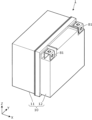
- FIG. 1 is a perspective view showing the appearance of a power storage device according to an embodiment.
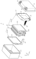
- FIG. 2 is an exploded perspective view showing each component of the electricity storage device according to the embodiment.
- FIG. 3 is a perspective view showing a second holding member according to the embodiment.
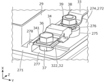
- FIG. 4 is a perspective view showing a connection structure between the other end of the bus bar and the fuse according to the embodiment.
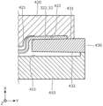
- FIG. 5 is a partial cross-sectional view of a second support region according to the embodiment.
- FIG. 6 is a cross-sectional view showing one step of a method for manufacturing an electricity storage device according to an embodiment.
- FIG. 7 is a cross-sectional view showing one step of a method for manufacturing an electricity storage device according to an embodiment.
- FIG. 8 is a cross-sectional view showing a process of a method for manufacturing an electricity storage device according to an embodiment.
- An energy storage device includes an energy storage element, a bus bar electrically connected to the energy storage element, a holding member that holds the bus bar with a portion of the bus bar fixed, and a conductive member that is joined to the bus bar, the bus bar protruding in a position facing one side of the holding member and having a protruding portion that is joined to the conductive member, the protruding portion having an opposing surface that faces the one side, and the distance between the one side and the opposing surface widens in a predetermined direction.
- the mold when insert molding the holding member and the bus bar, a mold is placed within the gap between one face of the holding member and the opposing face of the protrusion. Because the gap between one face of the holding member and the opposing face of the protrusion widens in a predetermined direction, the mold can be removed smoothly when it is removed in the predetermined direction. This makes it possible to suppress damage to the holding member and the protrusion, and improves the bond between the protrusion and the conductive member. In other words, the manufacturability and reliability of the energy storage device can be improved.
- the predetermined direction may be the protruding direction of the protrusion.
- the busbar becomes complicated. If the protruding direction of the protrusion is set to a specified direction as in this embodiment, the busbar can be prevented from becoming complicated.
- the protrusion may be generally inclined with respect to the predetermined direction.
- the entire protrusion is inclined in a predetermined direction, so that the distance between one surface of the retaining member and the opposing surface of the protrusion can be increased in the predetermined direction with a simple structure.
- the angle between the opposing surface and the one surface may be 0.5 degrees or more.
- the angle between the opposing surface and one surface is equal to or greater than the general draft angle (0.5 degrees), making it possible to remove the mold smoothly.
- the thickness of the conductive member may be smaller than the thickness of the protrusion.
- the thickness of the conductive member is smaller than the thickness of the protrusion, so the conductive member can be more easily deformed than the protrusion. Therefore, even if the protrusion is tilted, the conductive member can be deformed according to the tilt. This can improve the bond between the protrusion and the conductive member.
- a method for manufacturing an energy storage device is a method for manufacturing an energy storage device including an energy storage element, a busbar electrically connected to the energy storage element, and a holding member that holds the busbar with a portion of the busbar fixed, the method including: integrating the portion of the busbar and the holding member by insert molding in a position in which the portion of the busbar other than the portion forms a protrusion that protrudes from the holding member; and removing a mold disposed within the gap between one surface of the holding member and an opposing surface of the protrusion that faces the one surface, the gap expanding in a predetermined direction, in the predetermined direction.
- the mold when insert molding the holding member and the bus bar, the mold is placed within the gap between one face of the holding member and the opposing face of the protrusion. Since the gap between one face of the holding member and the opposing face of the protrusion widens in a predetermined direction, the mold can be removed smoothly in the predetermined direction. This can improve the manufacturability of the energy storage device.
- the X-axis direction is defined as the arrangement direction of the main body and the outer lid in the exterior body of the energy storage device, or the arrangement direction of the multiple energy storage elements in the energy storage device.
- the Y-axis direction is defined as the protruding direction of each lead terminal of the energy storage element.
- the Z-axis direction is defined as the arrangement direction of a pair of lead terminals in the energy storage element, or the up-down direction.
- the Z-axis direction may not be the up-down direction, but for convenience of explanation, the Z-axis direction will be described as the up-down direction below.
- the positive X-axis direction indicates the direction of the arrow on the X-axis
- the negative X-axis direction indicates the opposite side to the positive X-axis direction.
- expressions indicating a relative direction or attitude, such as parallel may also include cases where the direction or attitude is not strictly the same.
- two directions being perpendicular to each other does not only mean that the two directions are completely perpendicular to each other, but also means that the two directions are substantially perpendicular to each other, i.e., that there is a difference of, for example, about a few percent.
- insulation when the word "insulation” is used, it means "electrical insulation.”
- Fig. 1 is a perspective view showing the external appearance of the power storage device 1 according to an embodiment.
- Fig. 2 is an exploded perspective view showing each component of the power storage device 1 according to the embodiment when disassembled.
- the power storage device 1 is a device that can charge electricity from an external source and discharge electricity to the outside, and in this embodiment, has a substantially rectangular parallelepiped shape.
- the power storage device 1 is a battery module (battery pack) used for power storage or power supply.
- the power storage device 1 is used as a battery for driving or starting the engine of a moving object such as an automobile, a motorcycle, a watercraft, a ship, a snowmobile, an agricultural machine, a construction machine, an automatic guided vehicle (AGV: Automatic Guided Vehicle), or a railway vehicle for an electric railway.
- a moving object such as an automobile, a motorcycle, a watercraft, a ship, a snowmobile, an agricultural machine, a construction machine, an automatic guided vehicle (AGV: Automatic Guided Vehicle), or a railway vehicle for an electric railway.
- AGV Automatic Guided Vehicle
- Examples of the above-mentioned automobiles include electric vehicles (EVs), hybrid electric vehicles (HEVs), plug-in hybrid electric vehicles (PHEVs), and fossil fuel (gasoline, diesel, liquefied natural gas, etc.) vehicles.
- Examples of the above-mentioned railway vehicles for an electric railway include electric trains, monorails, linear motor cars, and hybrid electric trains equipped with both a diesel engine and an electric motor.
- the power storage device 1 can also be used as a stationary battery for home or business use.
- the energy storage device 1 includes an energy storage unit 20 and an exterior body 10 that houses the energy storage unit 20.
- the exterior body 10 includes a main body 11 that houses the energy storage unit 20 and an outer lid 12 that covers the main body 11.
- the exterior body 10 is a rectangular (box-shaped) container (module case) that constitutes the exterior body of the energy storage device 1.
- the exterior body 10 is a member that fixes the energy storage unit 20 and other elements in a predetermined position and protects these elements from impacts, etc.
- the main body 11 is a rectangular cylindrical member with a bottom that is open in the positive direction of the X-axis, and this open portion is the opening 111.
- the opening 111 is substantially rectangular in plan view (viewed in the X-axis direction).
- the opening 111 of the main body 11 contains a number of bus bars (not shown) and fuses (not shown) held by the energy storage unit 20.
- the outer lid 12 is a member that closes the opening 111 of the main body 11, and is joined to the main body 11 in a state in which the opening 111 of the main body 11 is closed from the positive direction of the X-axis.
- a circuit board 35 is disposed at a position outside the opening 111 that corresponds to the outer lid 12. In other words, the circuit board 35 is housed between the main body 11 and the outer lid 12.
- the outer lid 12 has a pair of external terminals 81 (positive and negative).
- the external terminals 81 are electrically connected to the multiple storage elements 21 included in the storage unit 20 via each bus bar, the fuse 34 (see FIG. 4), and the circuit board 35.
- the storage device 1 charges with electricity from the outside and discharges electricity to the outside via the external terminals 81.
- the external terminals 81 are formed of a conductive metal member such as a copper alloy such as brass, copper, aluminum, or an aluminum alloy.
- each bus bar is a plate-shaped member that electrically connects the external terminal 81 and the energy storage element 21.
- Each bus bar is formed of a conductive metal material such as copper, copper alloy, aluminum, aluminum alloy, etc.
- the fuse 34 is a component that protects the circuit board 35 and the multiple storage elements 21 from currents greater than the rated value. When a current greater than the rated value flows, the fuse melts to cut off the flow of current.
- the circuit board 35 has multiple electrical components (not shown), and these multiple electrical components form a detection circuit that detects the state (temperature, voltage, current, etc.) of each storage element 21, and a control circuit that controls charging and discharging. It is sufficient for the circuit board 35 to have at least one of the detection circuit and the control circuit.
- the main body 11 and the outer lid 12 of the exterior body 10 are formed of insulating materials such as polycarbonate (PC), polypropylene (PP), polyethylene (PE), polystyrene (PS), polyphenylene sulfide resin (PPS), polyphenylene ether (PPE (including modified PPE)), polyethylene terephthalate (PET), polybutylene terephthalate (PBT), polyether ether ketone (PEEK), tetrafluoroethylene perfluoroalkyl vinyl ether (PFA), polytetrafluoroethylene (PTFE), polyether sulfone (PES), polyamide (PA), ABS resin, or composite materials thereof, or metals with insulating coating.
- PC polycarbonate
- PP polypropylene
- PE polyethylene
- PS polystyrene
- PPS polyphenylene sulfide resin
- PPE polyphenylene ether
- PPE polyphenylene ether
- PPE including modified PPE
- the exterior body 10 may be formed of a conductive material such as metal as long as the electrical insulation of the storage element 21 and the like is maintained.
- the main body 11 and the outer lid 12 may be formed of the same material or different materials.
- the energy storage unit 20 includes a plurality of energy storage elements 21 and a holding portion 22 .
- the storage element 21 is a secondary battery (single cell), more specifically, a non-aqueous electrolyte secondary battery such as a lithium ion secondary battery.
- the storage element 21 is a pouch-type storage element having a flat shape, and a plurality of pouch-type storage elements 21 (four in this embodiment) are arranged in the X-axis direction.
- the storage element 21 may not be a pouch-type storage element, but may be a storage element having a flat rectangular parallelepiped (rectangular), cylindrical, oblong or elliptical cylindrical shape, etc., and the size and shape are not limited.
- the number of storage elements 21 arranged is also not particularly limited.
- the storage element 21 is not limited to a non-aqueous electrolyte secondary battery, and may be a secondary battery other than a non-aqueous electrolyte secondary battery, or may be a capacitor.
- the storage element 21 may not be a secondary battery, but may be a primary battery that can use the stored electricity without the user having to charge it.
- the multiple storage elements 21 are arranged in the X-axis direction, and adjacent storage elements 21 may or may not be joined together with adhesive or double-sided tape. Details of the storage elements 21 will be described later.
- the holding portion 22 is a portion that holds the multiple storage elements 21.
- the holding portion 22 has a first holding member 23 and a second holding member 24 that holds the multiple storage elements 21 together with the first holding member 23.
- the first holding member 23 is arranged in the negative X-axis direction of the multiple storage elements 21, and is joined by adhesive or double-sided tape to the storage element 21 arranged at the end of the multiple storage elements 21 in the negative X-axis direction.
- the second holding member 24 is arranged in the positive X-axis direction of the multiple storage elements 21, and is joined by adhesive or double-sided tape to the storage element 21 arranged at the end of the multiple storage elements 21 in the positive X-axis direction.
- the first holding member 23 and the second holding member 24 hold the multiple storage elements 21 by sandwiching them in the X-axis direction. It is sufficient that at least one of the first holding member 23 and the second holding member 24 is joined to the storage element 21.
- the first holding member 23 and the second holding member 24 are formed from an insulating resin material such as polycarbonate (PC), polypropylene (PP), polyethylene (PE), polyphenylene sulfide resin (PPS), polyphenylene ether (PPE (including modified PPE)), polyethylene terephthalate (PET), polybutylene terephthalate (PBT), polyether ether ketone (PEEK), tetrafluoroethylene perfluoroalkyl vinyl ether (PFA), polytetrafluoroethylene (PTFE), polyether sulfone (PES), polyamide (PA), ABS resin, or a composite material thereof.
- PC polycarbonate
- PP polypropylene
- PE polyethylene
- PPS polyphenylene sulfide resin
- PPE polyphenylene ether
- PET polyethylene terephthalate
- PBT polybutylene terephthalate
- PEEK polyether ether ketone
- PTFE polytetraflu
- the first holding member 23 and the second holding member 24 prevent the multiple storage elements 21 from becoming conductive with external conductive members such as metal members, but when such a need does not exist, the first holding member 23 and the second holding member 24 may be formed from a conductive member such as a metal.
- the first retaining member 23 has a flat plate portion 25 that overlaps with the energy storage element 21 at the end in the negative X-axis direction, and a busbar support portion 26 that extends in the positive X-axis direction from the flat plate portion 25.
- the busbar support portion 26 extends in the positive X-axis direction from the corners of the flat plate portion 25 in the negative Y-axis direction and the negative Z-axis direction, and supports a busbar (not shown).
- the second retaining member 24 will be described later.
- the multiple energy storage elements 21 have the same basic structure, but their external shapes are partially different. Specifically, the odd-numbered energy storage elements 21 in sequence from the negative X-axis direction have partially different external shapes from the even-numbered energy storage elements 21 in sequence from the negative X-axis direction. In other words, the odd-numbered energy storage elements 21 have the same external shape, and the even-numbered energy storage elements 21 have the same external shape.
- the energy storage element 21 has an exterior film 210 and a pair of lead terminals 220 (positive and negative electrodes), and an electrode body (not shown) and an electrolyte (non-aqueous electrolyte: not shown) are contained inside the exterior film 210.
- an electrode body not shown
- an electrolyte non-aqueous electrolyte: not shown
- the exterior film 210 is a sheet-like exterior body formed of a laminate film, and contains an electrode body, an electrolyte solution, etc., sealed under reduced pressure.
- the exterior film 210 is composed of two rectangular laminate films stacked in the X-axis direction. The two laminate films are joined (sealed) by heat welding or the like, sandwiching a pair of lead terminals 220 between them. In the two laminate films, the two laminate films are joined (sealed) by heat welding or the like at locations that do not correspond to the pair of lead terminals 220.
- the laminate film is a flexible film made of multiple layers including a metal layer such as aluminum and a resin layer such as polypropylene (PP) or polyethylene (PE), and the resin layer is disposed at the welding location (sealed portion).
- the exterior film 210 may be composed by forming a single laminate film into a bag shape and joining the ends of the laminate film together by heat welding.
- the lead terminals 220 are conductive plate-like members (lead plates) electrically connected to the electrode body, and are arranged so as to penetrate the exterior film 210 and be exposed from the exterior film 210.
- a pair of lead terminals 220 arranged in the Z-axis direction are arranged so as to protrude in the Y-axis negative direction from the end of the exterior film 210 in the Y-axis negative direction.
- the positive electrode lead terminal 220 is a lead terminal electrically connected to the positive electrode plate of the electrode body
- the negative electrode lead terminal 220 is a lead terminal electrically connected to the negative electrode plate of the electrode body.
- the lead terminals 220 are metal electrode terminals for conducting electricity stored in the electrode body to the external space of the storage element 21 and for introducing electricity into the internal space of the storage element 21 to store electricity in the electrode body.
- the lead terminals 220 are formed of aluminum, an aluminum alloy, copper, a copper alloy, or the like.
- the electrode body is a storage element (power generating element) formed by stacking a positive electrode plate, a negative electrode plate, and a separator.
- the positive electrode plate is a positive electrode active material layer formed on a current collector foil made of a metal such as aluminum or an aluminum alloy.
- the negative electrode plate is a negative electrode active material layer formed on a current collector foil made of a metal such as copper or a copper alloy.
- the active material used in the positive electrode active material layer and the negative electrode active material layer any known material can be used as long as it can absorb and release lithium ions.
- the separator can be a microporous sheet or nonwoven fabric made of resin.
- the electrode body is formed by stacking the electrode plates (positive electrode plate and negative electrode plate) in the X-axis direction.
- the electrode body may be of any shape, such as a wound type electrode body formed by winding the electrode plates (positive electrode plate and negative electrode plate), a stack type (stack type) electrode body formed by stacking multiple flat electrode plates, or a bellows type electrode body in which the electrode plates are folded in a bellows shape.
- Fig. 3 is a perspective view showing the second holding member 24 according to the embodiment.
- the second holding member 24 is a member that supports the bus bar 32, which is one of the above-mentioned bus bars, the circuit board 35, and the fuse 34 (see Fig. 4).
- the second holding member 24 is a member formed by insert molding the bus bar 32 with the above-mentioned resin member.
- the second holding member 24 is an example of a holding member that holds the bus bar 32 with a part of the bus bar 32 fixed (embedded).
- the second holding member 24 can also be said to be an insert molded body.
- the second retaining member 24 has a retaining body 27 that overlaps with the storage element 21 at the end in the positive direction of the X-axis, and a detection line support part 28 that extends from the retaining body 27 in the negative direction of the X-axis.
- the detection line support portion 28 is a portion that supports multiple detection lines (not shown) connected to the circuit board 35 in order to detect the state (temperature, voltage, current, etc.) of each storage element 21.
- the detection line support portion 28 extends in the negative X-axis direction from the end of the holding body 27 in the negative Y-axis direction.
- the holding body 27 is a member that supports the bus bar 32, the circuit board 35, and the fuse 34.
- the holding body 27 has a support plate portion 271 formed in a plate shape parallel to the ZY plane, and the main surface of the support plate portion 271 in the positive direction of the X axis supports the circuit board 35 and the fuse 34.
- the main surface 272 in the positive direction of the X axis of the support plate portion 271 the area that supports the circuit board 35 is called the first support area 273, and the area in the positive direction of the Y axis from the first support area 273 is called the second support area 274.
- the first support area 273 and the second support area 274 are aligned in the Y axis direction, and the first support area 273 is disposed in the negative direction of the Y axis from the second support area 274.
- the main surface 272 is provided with a surrounding wall 29 that surrounds the entire periphery of the first support area 273. The surrounding wall 29 does not surround the second support area 274.
- the second support region 274 is a region that supports the fuse 34, and a convex base portion 275 is disposed in the center in the Z-axis direction.
- a fitting hole 276 into which the head of the bolt 38 (see FIG. 4) fits is formed in the tip surface of this base portion 275.
- the bolt 38 is a fastener for fixing the fuse 34.
- a portion of the busbar 32 is fixed (embedded) in the end of the support plate portion 271 in the negative Z-axis direction.
- the busbar 32 is a metal plate extending in the Y-axis direction, with both ends of the busbar 32 in the Y-axis direction protruding from the support plate portion 271, and the middle portion of the busbar 32 being fixed (embedded) in the support plate portion 271.
- the middle portion of the busbar 32 is fixed (embedded) as a whole in the support plate portion 271. It is not essential that the middle portion of the busbar 32 be embedded.
- the middle portion of the busbar 32 may be fixed to the support plate portion 271 so that it is exposed from the support plate portion 271.
- One end 321 of the bus bar 32 in the negative Y-axis direction protrudes from the support plate portion 271 in the negative Y-axis direction, and is bent so that its tip faces the positive X-axis direction.
- a bus bar supported by the bus bar support portion 26 of the first retaining member 23 is connected to the one end 321.
- the other end 322 of the bus bar 32 in the positive Y-axis direction protrudes from the support plate portion 271 in the positive Y-axis direction and is connected to the fuse 34.
- the fuse 34 is an example of a conductive member joined to the bus bar 32.
- FIG. 4 is a perspective view showing the connection structure between the other end 322 of the bus bar 32 and the fuse 34 according to the embodiment.
- the fuse 34 extends in the Z-axis direction, and has leads 341 provided at both ends in the Z-axis direction.
- Each lead 341 is a plate extending in the Z-axis direction along the YZ plane.
- the lead 341 in the negative Z-axis direction of the fuse 34 is connected to the other end 322 of the bus bar 32 by a bolt 36 and a nut 37.
- the lead in the positive Z-axis direction of the fuse 34 (not shown) is connected to the bus bar 33 connected to the external terminal 81 in the positive Y-axis direction by a bolt 38 and a nut 39.
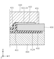
- FIG. 5 is a partial cross-sectional view of the second support region 274 according to the embodiment.
- FIG. 5 is a cross-sectional view taken along a cut surface parallel to the XY plane including line V-V in FIG. 3.
- FIG. 5 is a cross-sectional view of the portion of the second support region 274 from which the other end 322 of the busbar 32 protrudes.
- FIG. 5 shows auxiliary lines L1 and L2 parallel to the Y-axis direction.
- a step portion 277 and a support protrusion 278 are formed at the end of the second support region 274 in the negative Z-axis direction.
- Step portion 277 is a surface disposed in the negative X-axis direction from main surface 272.
- Step portion 277 is an inclined surface inclined with respect to the YZ plane (see auxiliary line L1).
- step portion 277 is a flat inclined surface that approaches the negative X-axis direction as it progresses in the positive Y-axis direction. If inclined in this manner, step portion 277 may be a curved surface.
- the support protrusion 278 is a portion that supports the bus bar 32.
- the support protrusion 278 protrudes in the positive direction of the X-axis and is curved in the positive direction of the Y-axis.
- the tip surface of the support protrusion 278 faces in the positive direction of the Y-axis, and the other end 322 of the bus bar 32 protrudes in the positive direction of the Y-axis from the tip surface of the support protrusion 278.
- a portion of the bus bar 32 that is further in the negative direction of the Y-axis than the other end 322 is fixed (embedded) inside the support protrusion 278.
- the portion of the bus bar 32 that is further in the negative direction of the Y-axis than the other end 322 is bent according to the shape of the support protrusion 278.
- the other end 322 of the busbar 32 protrudes in the positive direction of the Y-axis from the support protrusion 278 in a position facing the step portion 277, and is an example of a protrusion that is joined to the fuse 34.
- the other end 322 is formed in a flat plate shape and is generally inclined with respect to the YZ plane. Specifically, the other end 322 inclines toward the positive direction of the X-axis as it progresses in the positive direction of the Y-axis.
- the surface of the other end 322 in the negative direction of the X-axis is the opposing surface 323 that faces the step portion 277.
- the opposing surface 323 also inclines toward the positive direction of the X-axis as it progresses in the positive direction of the Y-axis.
- the step portion 277 inclines toward the negative direction of the X-axis as it progresses in the positive direction of the Y-axis
- the opposing surface 323 inclines toward the positive direction of the X-axis as it progresses in the positive direction of the Y-axis, so that the distance in the X-axis direction between the step portion 277 and the opposing surface 323 widens in the positive direction of the Y-axis.
- the distance between the step portion 277 and the facing surface 323 in the X-axis direction gradually increases toward the positive direction of the Y-axis.
- the angle ⁇ between the step portion 277 and the facing surface 323 is 0.5 degrees or more, and preferably 0.5 degrees or more and 3 degrees or less.
- the angle ⁇ is measured using a length measuring device. In particular, if the angle ⁇ exceeds 3 degrees, problems such as difficulty in joining the other end 322 of the busbar 32 and the lead 341 of the fuse 34, or the thickness of the support plate portion 271 of the second holding member 24 becoming thin, resulting in a decrease in the mechanical strength and insulating performance of the second holding member 24, occur.
- the thickness t1 (wall thickness: see FIG. 4) of the lead 341 of the fuse 34 is smaller than the thickness (wall thickness) t2 of the other end 322 of the busbar 32. This allows the lead 341 to deform in accordance with the inclination of the other end 322, allowing the lead 341 to be stably joined to the other end 322.
- FIG. 1 a manufacturing method of the energy storage device 1 will be described. Specifically, the insert molding of the second holding member 24, which is included in the manufacturing method of the energy storage device 1, will be described. The entire second holding member 24 is manufactured by insert molding, but here, an area including the step portion 277 and the support protrusion 278 of the second holding member 24 will be described as an example.
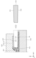
- Figures 6 to 8 are cross-sectional views showing one step of the manufacturing method of the energy storage device 1 according to the embodiment.
- the die 410 is a die arranged in the negative X-axis direction of the bus bar 32, and a recess 411 into which the molten resin material flows is formed on its surface in the positive X-axis direction.
- the die 420 is a die arranged in the positive X-axis direction of the bus bar 32, and a recess 421 into which the molten resin material flows and a recess 422 into which the other end 322 of the bus bar 32 fits are continuously formed on its surface in the negative X-axis direction of the die 420.
- the die 430 is arranged between the die 410 and the die 420 in the X-axis direction.
- the die 430 has a shape that tapers in the negative Y-axis direction when viewed in the Z-axis direction. Specifically, the surface 431 of the die 430 in the positive X-axis direction is inclined toward the negative X-axis direction as it progresses in the negative Y-axis direction. The surface 432 of the die 430 in the negative X-axis direction is inclined toward the positive X-axis direction as it progresses in the negative Y-axis direction. The surface 431 of the die 430 is in close contact with the opposing surface 323 of the other end 322 of the busbar 32. The surface 432 of the die 430 is used to form the step portion 277.
- Figure 7 shows the state in which molten resin material P has flowed into recesses 411 and 421.
- second retaining member 24 is formed with bus bar 32 insert molded therein.
- mold 430 is slid in the positive direction of the Y axis and removed from between the other end 322 of bus bar 32 and step portion 277.
- the gap in the X axis direction between opposing surface 323 of the other end 322 and step portion 277 widens in the positive direction of the Y axis, so that mold 430 can be smoothly removed, improving manufacturability.
- Manufacturability refers to the ease of manufacturing.
- the distance between the opposing surface 323 and the step portion 277 in the X-axis direction widens in the positive direction of the Y-axis, friction with the opposing surface 323 when the mold 430 is pulled out in the positive direction of the Y-axis can be reduced, and damage to the opposing surface 323 can be suppressed.
- deformation of the other end 322 of the busbar 32 can also be suppressed. If the other end 322 of the busbar 32 is deformed, it becomes difficult for the other end 322 of the busbar 32 and the lead 341 of the fuse 34 to come into close contact with each other, and the bondability decreases. Therefore, by suppressing deformation of the other end 322 of the busbar 32, the bondability between the other end 322 of the busbar 32 and the lead 341 of the fuse 34 can be suppressed from decreasing.
- the opposing surface 323 of the busbar 32 is covered with a plating layer, but if the friction during removal is reduced, peeling of the plating layer can be suppressed.
- the plating layer peels off the contact area between the other end 322 of the busbar 32 and the lead 341 decreases, and there is a risk of an increase in electrical resistance, but because peeling of the plating layer is suppressed, the increase in electrical resistance can also be suppressed.
- the mold 430 when the second holding member 24 (holding member) is insert-molded, the mold 430 is disposed within the gap between the step portion 277 (one surface) of the second holding member 24 and the opposing surface 323 of the other end 322 (protruding portion) of the bus bar 32. Since the gap between the step portion 277 and the opposing surface 323 widens in the Y-axis positive direction (predetermined direction), the mold 430 can be smoothly removed in the Y-axis positive direction. This can suppress damage to the second holding member 24 and the other end 322 (protruding portion), and improve the bonding between the other end 322 (protruding portion) and the lead 341 of the fuse 34. In other words, the manufacturability and reliability of the energy storage device 1 can be improved.
- the entire other end 322 is inclined with respect to the Y-axis direction, so the gap between the step portion 277 and the opposing surface 323 can be increased in the positive direction of the Y-axis with a simple structure.
- the angle ⁇ between the step portion 277 and the opposing surface 323 is equal to or greater than the typical draft angle (0.5 degrees), so the die 430 can be removed smoothly.
- the thickness t1 of the lead 341 of the fuse 34 is smaller than the thickness t2 of the other end 322 of the bus bar 32, making it easier to deform the fuse 34 than the other end 322. Therefore, even if the other end 322 is tilted, the fuse 34 can be deformed in accordance with the tilt. This improves the bonding between the other end 322 and the fuse 34.
- the mold 430 when insert molding the second retaining member 24 (retaining member), the mold 430 is placed within the gap between the step portion 277 (one surface) of the second retaining member 24 and the opposing surface 323 of the other end 322 (protruding portion) of the busbar 32. Since the gap between the step portion 277 and the opposing surface 323 widens in the positive direction of the Y axis (predetermined direction), the mold 430 can be removed smoothly in the positive direction of the Y axis. This can improve the manufacturability of the energy storage device 1.
- the opposing surface 323 of the other end 322 is inclined so that the distance between the step portion 277 and the opposing surface 323 is increased in the positive direction of the Y axis.
- the opposing surface 323 of the other end 322 may be inclined so that the distance between the step portion 277 and the opposing surface 323 is increased in the positive direction of the Z axis (or the negative direction of the Z axis).
- step portion 277 tilts toward the negative X-axis direction as it advances in the positive Y-axis direction
- the opposing surface 323 tilts toward the positive X-axis direction as it advances in the positive Y-axis direction, but only one of the step portion 277 and the opposing surface 323 may be tilted.
- the angle ⁇ between the step portion 277 and the opposing surface 323 is 0.5 degrees or more and 1.5 degrees or less, but the angle may be outside this range.
- the thickness t1 of the lead 341 of the fuse 34 is smaller than the thickness t2 of the other end 322 of the bus bar 32, but the thickness t1 may be greater than or equal to the thickness t2.
- the fuse 34 is given as an example of a conductive member connected to the other end 322 of the bus bar 32, but the conductive member is not limited to this.
- Other examples of conductive members include a bus bar, a voltage sensor, and a temperature sensor.
- the present invention can be applied to energy storage devices equipped with energy storage elements such as lithium-ion secondary batteries.
Landscapes
- Chemical & Material Sciences (AREA)
- Chemical Kinetics & Catalysis (AREA)
- Electrochemistry (AREA)
- General Chemical & Material Sciences (AREA)
- Inorganic Chemistry (AREA)
- Connection Of Batteries Or Terminals (AREA)
Abstract
Description
以下、図面を参照しながら、本発明の実施の形態(その変形例も含む)に係る蓄電装置について説明する。なお、以下で説明する実施の形態は、いずれも包括的または具体的な例を示すものである。以下の実施の形態で示される数値、形状、材料、構成要素、構成要素の配置位置及び接続形態などは、一例であり、本発明を限定する主旨ではない。各図において、寸法等は厳密に図示したものではない。各図において、同一または同様な構成要素については同じ符号を付している。本実施の形態の各構成部材(各構成要素)の名称は、本実施の形態におけるものであり、背景技術における各構成部材(各構成要素)の名称と異なる場合がある。
まず、図1及び図2を用いて、実施の形態に係る蓄電装置1の全般的な説明を行う。図1は、実施の形態に係る蓄電装置1の外観を示す斜視図である。図2は、実施の形態に係る蓄電装置1を分解した場合の各構成要素を示す分解斜視図である。
蓄電ユニット20は、複数の蓄電素子21と、保持部22とを備えている。
次に蓄電素子21の詳細について説明する。図2に示すように、複数の蓄電素子21は、基本的な構造は同様であるものの、外形形状が部分的に異なる。具体的には、X軸マイナス方向から順に奇数番目の蓄電素子21と、X軸マイナス方向から順に偶数番目の蓄電素子21とで、外形形状が部分的に異なっている。つまり、奇数番目の蓄電素子21同士は外形形状が同等であり、偶数番目の蓄電素子21同士は外形形状が同等である。
次に第二保持部材24について説明する。図3は、実施の形態に係る第二保持部材24を示す斜視図である。図2及び図3に示すように、第二保持部材24は、上述した各バスバーのひとつであるバスバー32と、回路基板35と、ヒューズ34(図4参照)とを支持する部材である。第二保持部材24は、上記した樹脂部材でバスバー32をインサート成形することにより形成された部材である。つまり、第二保持部材24は、バスバー32の一部が固定(埋設)された状態でバスバー32を保持する保持部材の一例である。第二保持部材24はインサート成形体とも言える。
次に、蓄電装置1の製造方法について説明する。具体的には、蓄電装置1の製造方法に含まれる第二保持部材24のインサート成形時について説明する。第二保持部材24の全体はインサート成形で製造されるが、ここでは、第二保持部材24の段差部277及び支持凸部278を含む領域を例示して説明する。図6~図8は、実施の形態に係る蓄電装置1の製造方法の一工程を示す断面図である。
以上のように、本実施の形態によれば、第二保持部材24(保持部材)のインサート成形時には、第二保持部材24の段差部277(一面)と、バスバー32の他端部322(突出部)の対向面323との間隔内に金型430が配置されている。段差部277と対向面323との間隔がY軸プラス方向(所定方向)に向けて広がっているので、金型430をY軸プラス方向に抜く際にスムーズに抜くことができる。これにより、第二保持部材24及び他端部322(突出部)の損傷を抑制でき、他端部322(突出部)とヒューズ34のリード341との接合性が向上する。つまり、蓄電装置1の製造性と信頼性を高めることができる。
以上、本発明の実施の形態に係る蓄電装置等について説明したが、本発明は、上記実施の形態に限定されるものではない。つまり、今回開示された実施の形態は、全ての点で例示であって制限的なものではなく、本発明の範囲には、請求の範囲と均等の意味及び範囲内での全ての変更が含まれる。
10 外装体
11 本体部
12 外蓋
20 蓄電ユニット
21 蓄電素子
22 保持部
23 第一保持部材
24 第二保持部材(保持部材)
25 平板部
26 バスバー支持部
27 保持本体
28 検出線支持部
29 囲壁
32、33 バスバー
34 ヒューズ(導電部材)
35 回路基板
36、38 ボルト
37、39 ナット
81 外部端子
111 開口部
210 外装フィルム
220 リード端子
271 支持板部
272 主面
273 第一支持領域
274 第二支持領域
275 台座部
276 嵌合穴
277 段差部(一面)
278 支持凸部
321 一端部
322 他端部(突出部)
323 対向面
341 リード
410、420、430 金型
411、421、422 凹部
431、432 面
L1、L2 補助線
P 樹脂材料
α 角度
Claims (6)
- 蓄電素子と、
前記蓄電素子に電気的に接続されるバスバーと、
前記バスバーの一部が固定された状態で前記バスバーを保持する保持部材と、
前記バスバーに接合される導電部材と、を備え、
前記バスバーは、前記保持部材の一面に対向する姿勢で突出し、前記導電部材に接合される突出部を備え、
前記突出部は、前記一面に対向する対向面を備え、
前記一面と前記対向面との間隔は、所定方向に向けて広がっている、
蓄電装置。 - 前記所定方向は、前記突出部の突出方向である、
請求項1に記載の蓄電装置。 - 前記突出部は、前記所定方向に対して全体的に傾いている、
請求項1または2に記載の蓄電装置。 - 前記対向面と前記一面とがなす角度は、0.5度以上である、
請求項1または2に記載の蓄電装置。 - 前記導電部材の厚さは、前記突出部の厚さよりも小さい、
請求項1または2に記載の蓄電装置。 - 蓄電素子と、
前記蓄電素子に電気的に接続されるバスバーと、
前記バスバーの一部が固定された状態で前記バスバーを保持する保持部材と、を備える蓄電装置の製造方法であって、
前記バスバーの前記一部以外の部分が前記保持部材から突出する突出部となる姿勢で、前記バスバーの前記一部と前記保持部材とをインサート成形によって一体化することと、
前記保持部材の一面と、前記一面に対向する前記突出部の対向面との間隔が所定方向に向けて広がっていて、前記間隔内に配置された金型を前記所定方向に向けて抜くことと、を含む、
蓄電装置の製造方法。
Priority Applications (5)
| Application Number | Priority Date | Filing Date | Title |
|---|---|---|---|
| JP2025526056A JPWO2024252966A1 (ja) | 2023-06-08 | 2024-05-27 | |
| CN202480037992.7A CN121285904A (zh) | 2023-06-08 | 2024-05-27 | 蓄电装置及其制造方法 |
| KR1020257040497A KR20260021621A (ko) | 2023-06-08 | 2024-05-27 | 축전 장치 및 그 제조 방법 |
| DE112024002461.0T DE112024002461T5 (de) | 2023-06-08 | 2024-05-27 | Energiespeichervorrichtung und verfahren zu deren herstellung |
| US19/401,653 US20260081309A1 (en) | 2023-06-08 | 2025-11-26 | Energy storage apparatus and method for manufacturing the same |
Applications Claiming Priority (2)
| Application Number | Priority Date | Filing Date | Title |
|---|---|---|---|
| JP2023-094587 | 2023-06-08 | ||
| JP2023094587 | 2023-06-08 |
Related Child Applications (1)
| Application Number | Title | Priority Date | Filing Date |
|---|---|---|---|
| US19/401,653 Continuation US20260081309A1 (en) | 2023-06-08 | 2025-11-26 | Energy storage apparatus and method for manufacturing the same |
Publications (1)
| Publication Number | Publication Date |
|---|---|
| WO2024252966A1 true WO2024252966A1 (ja) | 2024-12-12 |
Family
ID=93795896
Family Applications (1)
| Application Number | Title | Priority Date | Filing Date |
|---|---|---|---|
| PCT/JP2024/019339 Ceased WO2024252966A1 (ja) | 2023-06-08 | 2024-05-27 | 蓄電装置及びその製造方法 |
Country Status (6)
| Country | Link |
|---|---|
| US (1) | US20260081309A1 (ja) |
| JP (1) | JPWO2024252966A1 (ja) |
| KR (1) | KR20260021621A (ja) |
| CN (1) | CN121285904A (ja) |
| DE (1) | DE112024002461T5 (ja) |
| WO (1) | WO2024252966A1 (ja) |
Citations (4)
| Publication number | Priority date | Publication date | Assignee | Title |
|---|---|---|---|---|
| JPH11149913A (ja) * | 1997-11-18 | 1999-06-02 | Furukawa Battery Co Ltd:The | 鉛蓄電池のセル間接続方法 |
| WO2016199558A1 (ja) * | 2015-06-12 | 2016-12-15 | 株式会社Gsユアサ | 蓄電装置 |
| JP2018031554A (ja) * | 2016-08-26 | 2018-03-01 | Toto株式会社 | 空気調和機 |
| WO2022239559A1 (ja) * | 2021-05-11 | 2022-11-17 | 株式会社Gsユアサ | 蓄電装置 |
Family Cites Families (1)
| Publication number | Priority date | Publication date | Assignee | Title |
|---|---|---|---|---|
| JP7138580B2 (ja) | 2019-01-31 | 2022-09-16 | マレリ株式会社 | 組電池 |
-
2024
- 2024-05-27 CN CN202480037992.7A patent/CN121285904A/zh active Pending
- 2024-05-27 JP JP2025526056A patent/JPWO2024252966A1/ja active Pending
- 2024-05-27 WO PCT/JP2024/019339 patent/WO2024252966A1/ja not_active Ceased
- 2024-05-27 KR KR1020257040497A patent/KR20260021621A/ko active Pending
- 2024-05-27 DE DE112024002461.0T patent/DE112024002461T5/de active Pending
-
2025
- 2025-11-26 US US19/401,653 patent/US20260081309A1/en active Pending
Patent Citations (4)
| Publication number | Priority date | Publication date | Assignee | Title |
|---|---|---|---|---|
| JPH11149913A (ja) * | 1997-11-18 | 1999-06-02 | Furukawa Battery Co Ltd:The | 鉛蓄電池のセル間接続方法 |
| WO2016199558A1 (ja) * | 2015-06-12 | 2016-12-15 | 株式会社Gsユアサ | 蓄電装置 |
| JP2018031554A (ja) * | 2016-08-26 | 2018-03-01 | Toto株式会社 | 空気調和機 |
| WO2022239559A1 (ja) * | 2021-05-11 | 2022-11-17 | 株式会社Gsユアサ | 蓄電装置 |
Also Published As
| Publication number | Publication date |
|---|---|
| KR20260021621A (ko) | 2026-02-13 |
| JPWO2024252966A1 (ja) | 2024-12-12 |
| US20260081309A1 (en) | 2026-03-19 |
| CN121285904A (zh) | 2026-01-06 |
| DE112024002461T5 (de) | 2026-03-19 |
Similar Documents
| Publication | Publication Date | Title |
|---|---|---|
| US20130045401A1 (en) | Battery pack and battery module comprising the same | |
| CN114464900A (zh) | 电池 | |
| EP4116998A1 (en) | Power storage device | |
| CN115719864B (zh) | 电池 | |
| US20250192334A1 (en) | Energy storage apparatus | |
| JP2025134067A (ja) | 蓄電デバイス | |
| CN113261149A (zh) | 蓄电装置 | |
| US20240021964A1 (en) | Battery and electrode terminal | |
| US20240372165A1 (en) | Energy storage apparatus | |
| US20260081309A1 (en) | Energy storage apparatus and method for manufacturing the same | |
| US20240234979A1 (en) | Energy storage apparatus | |
| JP7427903B2 (ja) | 蓄電装置 | |
| JP7524551B2 (ja) | 蓄電装置 | |
| WO2022163668A1 (ja) | 蓄電装置 | |
| JP7713923B2 (ja) | 蓄電デバイス | |
| US20250260118A1 (en) | Energy storage apparatus | |
| US20260005354A1 (en) | Energy storage apparatus | |
| US20250266558A1 (en) | Energy storage apparatus | |
| JP7559410B2 (ja) | 蓄電装置 | |
| JP7596661B2 (ja) | 蓄電装置 | |
| JP7552032B2 (ja) | 蓄電装置 | |
| JP2025090178A (ja) | 蓄電装置 | |
| WO2024038729A1 (ja) | 蓄電装置 | |
| JP2025163460A (ja) | 蓄電装置 | |
| JP2025008947A (ja) | 蓄電装置 |
Legal Events
| Date | Code | Title | Description |
|---|---|---|---|
| 121 | Ep: the epo has been informed by wipo that ep was designated in this application |
Ref document number: 24819198 Country of ref document: EP Kind code of ref document: A1 |
|
| ENP | Entry into the national phase |
Ref document number: 2025526056 Country of ref document: JP Kind code of ref document: A |
|
| WWE | Wipo information: entry into national phase |
Ref document number: 2025526056 Country of ref document: JP |
|
| WWE | Wipo information: entry into national phase |
Ref document number: 112024002461 Country of ref document: DE |
|
| WWP | Wipo information: published in national office |
Ref document number: 112024002461 Country of ref document: DE |