WO2024252948A1 - 電気脱イオン装置、そのメンテナンス方法、及び電気脱イオン装置の管理方法 - Google Patents
電気脱イオン装置、そのメンテナンス方法、及び電気脱イオン装置の管理方法 Download PDFInfo
- Publication number
- WO2024252948A1 WO2024252948A1 PCT/JP2024/019107 JP2024019107W WO2024252948A1 WO 2024252948 A1 WO2024252948 A1 WO 2024252948A1 JP 2024019107 W JP2024019107 W JP 2024019107W WO 2024252948 A1 WO2024252948 A1 WO 2024252948A1
- Authority
- WO
- WIPO (PCT)
- Prior art keywords
- compartments
- electrodeionization
- electrodeionization device
- exchange membranes
- deionization
- Prior art date
- Legal status (The legal status is an assumption and is not a legal conclusion. Google has not performed a legal analysis and makes no representation as to the accuracy of the status listed.)
- Ceased
Links
Images

Classifications
-
- C—CHEMISTRY; METALLURGY
- C02—TREATMENT OF WATER, WASTE WATER, SEWAGE, OR SLUDGE
- C02F—TREATMENT OF WATER, WASTE WATER, SEWAGE, OR SLUDGE
- C02F1/00—Treatment of water, waste water, or sewage
- C02F1/42—Treatment of water, waste water, or sewage by ion-exchange
-
- C—CHEMISTRY; METALLURGY
- C02—TREATMENT OF WATER, WASTE WATER, SEWAGE, OR SLUDGE
- C02F—TREATMENT OF WATER, WASTE WATER, SEWAGE, OR SLUDGE
- C02F1/00—Treatment of water, waste water, or sewage
- C02F1/46—Treatment of water, waste water, or sewage by electrochemical methods
- C02F1/469—Treatment of water, waste water, or sewage by electrochemical methods by electrochemical separation, e.g. by electro-osmosis, electrodialysis, electrophoresis
Definitions
- the present invention relates to an electrodeionization device used in a pure water production system, a maintenance method thereof, and a management method for the electrodeionization device, and in particular to an electrodeionization device that is easy to maintain and to manage water quality, a maintenance method thereof, and a management method for the electrodeionization device.
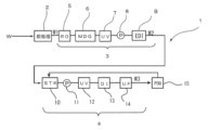
- ultrapure water used in the semiconductor and other electronics industries is produced, for example, by an ultrapure water production system 1 as shown in Figure 3.
- This ultrapure water production system 1 is composed of three stages of equipment: a pretreatment device 2, a primary pure water production system 3, and a secondary pure water production system (subsystem) 4.
- the pretreatment device 2 of this ultrapure water production system 1 the raw water W is pretreated by filtration, coagulation and sedimentation, and using a microfiltration membrane, and mainly suspended solids are removed.
- the primary pure water production system 3 has a reverse osmosis membrane device 5 that treats the pretreated water W1, a deaeration membrane device 6, an ultraviolet oxidation device 7, an electric deionization device 9, and a water supply pump 8 that supplies water to the electric deionization device 9.
- This primary pure water production system 3 removes most of the electrolytes, fine particles, live bacteria, etc. from the pretreated water W1 and also decomposes organic matter.
- the subsystem 4 is composed of a subtank 10 for storing the primary pure water W2 produced by the primary pure water production device 3, an ultraviolet oxidation device 12 for processing the primary pure water W2 delivered from the subtank 10 via a pump 11, a non-regenerative mixed-bed ion exchange device 13, and an ultrafiltration (UF) membrane 14 as a particulate removal means, and may further include an RO membrane separation device or the like as necessary.
- the ultraviolet oxidation device 12 oxidizes and decomposes trace amounts of organic matter (TOC components) contained in the primary pure water W2, and then the non-regenerative mixed-bed ion exchange device 13 processes the water to remove residual carbonate ions, organic acids, anionic substances, and even metal ions and cationic substances by ion exchange. Then, the ultrafiltration (UF) membrane 14 removes particulates to produce ultrapure water W3, which is supplied to the point of use 15, and unused ultrapure water is returned to the subtank 10.
- TOC components organic matter contained in the primary pure water W2
- the non-regenerative mixed-bed ion exchange device 13 processes the water to remove residual carbonate ions, organic acids, anionic substances, and even metal ions and cationic substances by ion exchange.
- the ultrafiltration (UF) membrane 14 removes particulates to produce ultrapure water W3, which is supplied to the point of use 15, and unused ultrapure water is returned to the subtank 10.
- the primary pure water production device 3 used in such an ultrapure water production device 1 is a highly versatile device that is used in various fields such as medicine and food, in addition to the field of ultrapure water production.
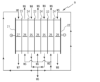
- the electric deionization device 9 has a plurality of cation exchange membranes 23 and anion exchange membranes 24 arranged alternately between electrodes (anode 21, cathode 22) to form deionization chambers 25 and concentration chambers 26 alternately, and the deionization chambers 25 are filled with ion exchangers (anion exchangers and cation exchangers) made of ion exchange resins, ion exchange fibers, graft exchangers, etc., in a mixed or multi-layered form.
- ion exchangers anion exchangers and cation exchangers
- concentration chambers 26, the anode chamber 27, and the cathode chamber 28 are also filled with ion exchangers.
- the deionization chambers 25 and the concentration chambers 26 are filled with a mixed ion exchange resin in which anion exchange resin and cation exchange resin are mixed in a predetermined ratio.
- This electric deionization device 9 is provided with a water passing means (not shown) that passes the feed water (water to be treated) W4 through the desalting chamber 25 to extract treated water (desalinated water) W5, and a concentrated water passing means (not shown) that passes the concentrated water through the concentration chamber 26.
- the concentrated water is introduced into the concentration chamber 26 from the side of the desalting chamber 25 close to the outlet for the desalted water W5, and flows out from the side of the desalting chamber 25 close to the inlet for the feed water W4.
- the concentrated water (desalinated water) W5 is introduced into the concentration chamber 26 from the direction opposite to the flow direction of the feed water W4 in the desalting chamber 25, and concentrated water W6 is discharged.
- the desalted water W5 is also supplied to the anode chamber 27 and the cathode chamber 28, and the electrode chamber wastewater W7 and W8 are discharged, respectively.
- the current problem is that, because it is difficult to perform maintenance such as regenerating or replacing the ion exchange resin filled in the deionization chamber 25, the entire electrodeionization device 9 must be replaced, and the exterior of the electrodeionization device 9 and the electrodes (anode 21, cathode 22) must also be discarded.
- the electrodeionization device 9 because large electrodeionization devices are often made to order, it is difficult to immediately replace the electrodeionization device 9 even if it suddenly becomes necessary to replace it.
- the present invention has been made in consideration of the above problems, and aims to provide an electrodeionization apparatus that is easy to maintain and allows easy water quality management. It also aims to provide a maintenance method for an electrodeionization apparatus that is easy to maintain and allows for reduced waste. Furthermore, the present invention aims to provide a management method for an electrodeionization apparatus that is easy to maintain and allows easy water quality management.
- the present invention first provides an electrodeionization device having a cathode and an anode, and concentrating and deionizing compartments formed alternately by arranging a plurality of cation exchange membranes and anion exchange membranes between the cathode and anode, the deionizing and concentrating compartments being filled with ion exchange resin, the deionizing and concentrating compartments being formed in a cell pack structure formed within a frame together with the cation exchange membranes and anion exchange membranes that constitute them, a plurality of such cell packs being connected to form an integrated structure in which the concentrating and deionizing compartments are arranged alternately, and the integrated structure being detachable from the electrodeionization device (Invention 1).
- invention 1 when the ion exchange resin filled in the desalting and concentrating compartments of the electrodeionization device deteriorates, maintenance of the electrodeionization device can be performed and performance can be restored simply by removing and replacing the integrated structure formed by the cell pack. Moreover, the exterior and electrodes of the electrodeionization device can continue to be used.
- the present invention provides a method for maintaining an electrodeionization device, which has a cathode and an anode, and alternating concentration chambers and deionization chambers formed by arranging a plurality of cation exchange membranes and anion exchange membranes between the cathode and anode, the deionization chambers and concentration chambers being filled with ion exchange resin, the deionization chambers and concentration chambers being formed in a frame together with the cation exchange membranes and anion exchange membranes that constitute them, a cell pack structure, and a plurality of such cell packs are connected to form an integrated structure in which the concentration chambers and deionization chambers are arranged alternately, the integrated structure being detachable from the electrodeionization device, and the integrated structure is removed from the electrodeionization device and replaced (Invention 2).
- the present invention provides a method for managing an electrodeionization apparatus having a cathode and an anode, and concentrating and deionizing compartments formed alternately by arranging a plurality of cation exchange membranes and anion exchange membranes between the cathode and anode, the deionizing and concentrating compartments being filled with ion exchange resin, the deionizing and concentrating compartments being formed in a cell pack structure together with the cation exchange membranes and anion exchange membranes that constitute them, respectively, within a frame, and a plurality of such cell packs being connected to form an integrated structure in which the concentrating and deionizing compartments are arranged alternately, the integrated structure being detachable from the electrodeionization apparatus, and the method for managing an electrodeionization apparatus determines the time to replace the integrated structure based on the operation information of the electrodeionization apparatus or treated water information (Invention 3).
- the operating information of the electrodeionization device is a water flow differential pressure calculated from the water supply pressure of the desalting chamber of the electrodeionization device and the treated water pressure (Invention 5).
- the treated water information of the electrodeionization device is the resistivity or conductivity of the treated water of the electrodeionization device (Invention 6).
- FIG. 1 is a schematic diagram illustrating an electrodeionization apparatus according to one embodiment of the present invention.
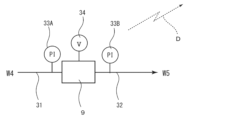
- FIG. 2 is a schematic diagram showing a management system for the electrodeionization apparatus of the embodiment.
- FIG. 1 is a schematic diagram showing an ultrapure water production apparatus as an application example of an electrodeionization apparatus.
- FIG. 1 is a schematic diagram showing a conventional electrodeionization apparatus.
- the electrodeionization apparatus of the present invention has a cathode, an anode, and concentrating compartments and deionization compartments alternately formed by arranging a plurality of cation exchange membranes and anion exchange membranes between the cathode and anode, and the deionization compartments and concentrating compartments are filled with ion exchange resin, and is basically the same in configuration as the electrodeionization apparatus shown in Fig. 4. Therefore, in the electrodeionization apparatus shown in Fig. 1, the same components as those in the electrodeionization apparatus shown in Fig. 4 are denoted by the same reference numerals, and detailed description thereof will be omitted.
- the electrodeionization device 9 has deionization chambers 25 and concentration chambers 26 formed by alternately arranging cation exchange membranes 23 and anion exchange membranes 24, which are installed in a frame together with the cation exchange membranes 23 and anion exchange membranes 24 to form a cell pack, and multiple such cell packs are connected to form an integrated structure 9A.
- This integrated structure 9A is detachable from the electrodeionization device 9. It is preferable to stock multiple types of integrated structures 9A, each of which is made by connecting multiple cell packs, in advance, with the ratio of anion exchange resin and cation exchange resin filled in the deionization chambers being changed in various ways depending on the required water quality, etc.
- a maintenance method for the electrodeionization apparatus 9 as described above will be described below. Maintenance of the electrodeionization device 9 becomes necessary when the quality of the treated water W5 of the electrodeionization device 9 deteriorates, a predetermined period of use has elapsed, or a predetermined cumulative amount of treated water has been reached. In the past, the electrodeionization device 9 was replaced as a whole at such times. In contrast, in this embodiment, the integrated structure 9A in which multiple cell packs are connected is detachable, so that maintenance of the electrodeionization device 9 can be performed and its performance can be restored simply by removing and replacing this integrated structure 9A. Moreover, the exterior of the electrodeionization device 9 and the electrodes (anode 21, cathode 22) can be continuously used, which helps reduce waste.
- FIG. 2 shows a management system for the electrodeionization apparatus 9.
- the electrodeionization apparatus 9 constitutes a part of a pure water production apparatus (primary pure water production apparatus), and a supply pipe 31 and a discharge pipe 32 are connected to the supply side and the discharge side of the desalting compartment of the electrodeionization apparatus 9, respectively.
- the supply pipe 31 is provided with a pressure gauge 33A for measuring the water pressure of the feed water W4, and the discharge pipe 32 is provided with a pressure gauge 33B for measuring the water pressure of the desalted water W5.
- a voltmeter 34 is provided in the power supply device of the electrodeionization apparatus 9.
- the measured values of the pressure gauges 33A and 33B and the measured value of the voltmeter 34, which serve as operating information, can be transmitted as operating information D by a transmitter (not shown) provided at a remote location.
- This determination can be made, for example, by setting a threshold value for the water flow differential pressure in advance, and using the point in time when the water flow differential pressure calculated from the measurement values of pressure gauge 33A and pressure gauge 33B exceeds this threshold as a reference, and determining whether it is time to replace integrated structure 9A immediately or after a predetermined period of time has passed.
- the reference since the water flow differential pressure may temporarily exceed the threshold value, the reference may also be the point in time when the water flow differential pressure exceeds the threshold value for a predetermined period of time. Furthermore, the reference may also be the point in time when the upward trend in the water flow differential pressure becomes more than a certain gradient (a certain or more rise in spring water differential pressure per unit time).
- the measurement value information D of the voltmeter 34 is sent to the management equipment.
- the management equipment determines the time to replace the integrated structure 9A, which is made up of multiple connected cell packs, based on the information from the voltmeter 34.
- This determination can be made, for example, by setting a threshold value for the operating voltage in advance, and using the point in time when the measurement value of the voltmeter 34 exceeds this threshold as the reference point, whether immediately or after a predetermined period of time has passed, as the time to replace the integrated structure 9A.
- the reference point may also be the point in time when the operating voltage exceeds the threshold value for a predetermined period of time.
- the reference point may also be the point in time when the upward trend of the operating voltage reaches a certain gradient or more (pressure increase of a certain amount or more per unit time).
- the timing for replacing the integrated structure 9A which is made up of multiple connected cell packs, can be appropriately determined, and water quality management can be easily performed.
- the performance of the electrodeionization device 9 can be restored simply by identifying the type of integrated structure 9A at the management facility and transporting and replacing the integrated structure 9A.
- a resistivity meter for measuring the resistivity of the desalted water W5 and a conductivity meter for measuring the conductivity may be provided in the discharge pipe 32, and the resistivity value decreases as the water quality decreases, so the electrodeionization device 9 may be managed based on the resistivity value of the desalted water W5 as treated water information.
- a particle meter may be provided in the discharge pipe 32, and the electrodeionization device 9 may be managed based on the number of particles in the desalted water W5 as treated water information.
- the direction of water flow is not limited, and the electrodeionization device can be applied to various electrodeionization devices.
- Electrodeionization apparatus 9A Integrated structure in which a plurality of cell packs are connected 21 Anode (electrode) 22 Cathode (electrode) 23 Cation exchange membrane 24 Anion exchange membrane 25 Deionization chamber 26 Concentration chamber 27 Anode chamber 28 Cathode chamber 31 Supply pipe 32 Discharge pipes 33A, 33B Pressure gauge 34 Voltmeter W Raw water W1 Pretreated water (supply water) W2 Primary pure water (demineralized water) W3 Ultrapure water (secondary pure water) W4 Water supply (water to be treated) W5 Desalinated water (treated water) W6 Concentrated water W7, W8 Electrode room drainage D Operating information
Landscapes
- Chemical & Material Sciences (AREA)
- Life Sciences & Earth Sciences (AREA)
- Organic Chemistry (AREA)
- Environmental & Geological Engineering (AREA)
- Water Supply & Treatment (AREA)
- Engineering & Computer Science (AREA)
- Hydrology & Water Resources (AREA)
- Chemical Kinetics & Catalysis (AREA)
- Health & Medical Sciences (AREA)
- Analytical Chemistry (AREA)
- Molecular Biology (AREA)
- Electrochemistry (AREA)
- General Chemical & Material Sciences (AREA)
- Water Treatment By Electricity Or Magnetism (AREA)
- Treatment Of Water By Ion Exchange (AREA)
Abstract
電気脱イオン装置9は、電極(陽極21、陰極22)の間に複数のカチオン交換膜23及びアニオン交換膜24を交互に配列して脱塩室25と濃縮室26とを交互に形成したものであり、脱塩室25には、イオン交換樹脂が混合もしくは複層状に充填されている。脱塩室25と濃縮室26は、カチオン交換膜23とアニオン交換膜24とを交互に配列して形成した脱塩室25と濃縮室26をカチオン交換膜23とアニオン交換膜24とともにフレーム内に設置してセルパックとし、このセルパックを複数連結した一体型構造体9Aにより構成する。この一体型構造体9Aは、電気脱イオン装置9から着脱可能となっている。このような電気脱イオン装置であれば、メンテナンス性が良好で水質管理も容易である。
Description
本発明は、純水製造装置に用いられる電気脱イオン装置、そのメンテナンス方法、及び電気脱イオン装置の管理方法に関し、特にメンテナンス性が良好で水質管理の容易な電気脱イオン装置、そのメンテナンス方法、及び電気脱イオン装置の管理方法に関する。
従来、半導体等の電子産業分野で用いられている超純水は、例えば、図3に示すような超純水製造装置1により製造される。この超純水製造装置1は、前処理装置2、一次純水製造装置3、及び二次純水製造装置(サブシステム)4といった3段の装置で構成されている。このような超純水製造装置1の前処理装置2では、原水Wの濾過、凝集沈殿、精密濾過膜などによる前処理が施され、主に懸濁物質が除去される。
一次純水製造装置3は、前処理水W1を処理する逆浸透膜装置5と、脱気膜装置6と、紫外線酸化装置7と、電気脱イオン装置9と、この電気脱イオン装置9に給水を供給する給水ポンプ8とを有する。この一次純水製造装置3で前処理水W1中の大半の電解質、微粒子、生菌等の除去を行うとともに有機物を分解する。
サブシステム4は、一次純水製造装置3で製造された一次純水W2を貯留するサブタンク10とこのサブタンク10からポンプ11を介して送給される一次純水W2を処理する紫外線酸化装置12と非再生型混床式イオン交換装置13と微粒子除去手段としての限外濾過(UF)膜14とで構成され、さらに必要に応じRO膜分離装置等が設けられている場合もある。このサブシステム4では、紫外線酸化装置12により一次純水W2中に含まれる微量の有機物(TOC成分)を酸化分解し、続いて非再生型混床式イオン交換装置13で処理することで残留した炭酸イオン、有機酸類、アニオン性物質、さらには金属イオンやカチオン性物質をイオン交換によって除去する。そして、限外濾過(UF)膜14で微粒子を除去して超純水W3とし、これをユースポイント15に供給して、未使用の超純水はサブタンク10に返送する。
このような超純水製造装置1に用いられる一次純水製造装置3は、超純水製造の分野以外にも、医薬用や食品用などの様々な分野に利用されている汎用性の高い装置である。ここで、図4に示すように電気脱イオン装置9は、電極(陽極21、陰極22)の間に複数のカチオン交換膜23及びアニオン交換膜24を交互に配列して脱塩室25と濃縮室26とを交互に形成したものであり、脱塩室25には、イオン交換樹脂、イオン交換繊維もしくはグラフト交換体等からなるイオン交換体(アニオン交換体及びカチオン交換体)が混合もしくは複層状に充填されている。また、濃縮室26と、陽極室27に陰極室28にもイオン交換体が充填されている。一般的には、この脱塩室25及び濃縮室26には、アニオン交換樹脂とカチオン交換樹脂とを所定の割合で混合した混合イオン交換樹脂が充填されている。
この電気脱イオン装置9には、脱塩室25に給水(被処理水)W4を通水して処理水(脱塩水)W5を取り出す通水手段(図示せず)と、濃縮室26に被濃縮水を通水する濃縮水通水手段(図示せず)とが設けられていて、ここでは、被濃縮水を脱塩室25の脱塩水W5の取り出し口に近い側から濃縮室26内に導入すると共に、脱塩室25の給水W4の入口に近い側から流出する。すなわち脱塩室25における給水W4の流通方向と反対方向から被濃縮水(脱塩水)W5を濃縮室26に導入して濃縮水W6を吐出する構成となっている。さらに、脱塩水W5は、陽極室27及び陰極室28にも供給されて、電極室排水W7,W8をそれぞれ吐出する。
上述したような電気脱イオン装置9は、トータル処理水量が増加して脱塩室25に充填されているイオン交換樹脂が劣化すると、定電流運転において運転電圧が上昇し、消費電力量の増加を招くだけでなく、さらに電圧が上昇すると運転が困難になる。また、充填されているイオン交換樹脂が破砕し、微粒子としてリークし水質の低下を招く。
しかしながら、このように電気脱イオン装置9はその性能が低下しても、脱塩室25に充填されたイオン交換樹脂を再生したり、交換したりするメンテナンスが困難であることから、現状では電気脱イオン装置9ごと交換せざるをえず、電気脱イオン装置9の外装や電極(陽極21、陰極22)も廃棄せざるを得ない、という問題点がある。また、大型の電気脱イオン装置は、受注生産することが多いため、突然電気脱イオン装置9の交換が必要になっても直ちに交換するのが困難である。
本発明は、上記課題に鑑みてなされたものであり、メンテナンス性が良好で水質管理の容易な電気脱イオン装置を提供することを目的とする。また、メンテナンスが簡単で廃棄物の削減が可能な電気脱イオン装置のメンテナンス方法を提供することを目的とする。さらに、本発明は、メンテナンス性が良く水質管理の容易な電気脱イオン装置の管理方法を提供することを目的とする。
上記目的に鑑み、本発明は第一に、陰極及び陽極と、該陰極と陽極との間に複数のカチオン交換膜とアニオン交換膜とを配列することにより交互に形成された濃縮室及び脱塩室とを有し、前記脱塩室及び濃縮室にイオン交換樹脂が充填されている電気脱イオン装置であって、前記脱塩室及び濃縮室がこれらを構成するカチオン交換膜及びアニオン交換膜とともにそれぞれフレーム内に形成されたセルパック構造であり、このセルパックを複数連結して濃縮室及び脱塩室を交互に配置した一体型構造体となっていて、該一体型構造体が前記電気脱イオン装置から着脱可能である、電気脱イオン装置を提供する(発明1)。
かかる発明(発明1)によれば、電気脱イオン装置の脱塩室及び濃縮室に充填されているイオン交換樹脂が劣化したら、セルパックにより構成される一体構造体を取り出して交換するだけで、電気脱イオン装置のメンテナンスを実施して、性能を回復することができる。しかも、電気脱イオン装置の外装や電極は継続して利用することができる。
また、本発明は第二に、陰極及び陽極と、該陰極と陽極との間に複数のカチオン交換膜とアニオン交換膜とを配列することにより交互に形成された濃縮室及び脱塩室とを有し、前記脱塩室及び濃縮室にイオン交換樹脂が充填されており、前記脱塩室及び濃縮室がこれらを構成するカチオン交換膜及びアニオン交換膜とともにそれぞれフレーム内に形成されたセルパック構造であり、このセルパックを複数連結して濃縮室及び脱塩室を交互に配置した一体型構造体となっていて、該一体型構造体が前記電気脱イオン装置から着脱可能である電気脱イオン装置のメンテナンス方法であって、前記一体型構造体を前記電気脱イオン装置から取り出して交換する、電気脱イオン装置のメンテナンス方法を提供する(発明2)。
かかる発明(発明2)によれば、電気脱イオン装置の脱塩室及び濃縮室に充填されているイオン交換樹脂が劣化したら、セルパックにより構成される一体構造体を取り出して交換するだけで、電気脱イオン装置のメンテナンスを実施して、性能を回復することができる。しかも、電気脱イオン装置の外装や電極は継続して利用することができる。
さらに本発明は第三に、陰極及び陽極と、該陰極と陽極との間に複数のカチオン交換膜とアニオン交換膜とを配列することにより交互に形成された濃縮室及び脱塩室とを有し、前記脱塩室及び濃縮室にイオン交換樹脂が充填されており、前記脱塩室及び濃縮室がこれらを構成するカチオン交換膜及びアニオン交換膜とともにそれぞれフレーム内に形成されたセルパック構造であり、このセルパックを複数連結して濃縮室及び脱塩室を交互に配置した一体型構造体となっていて、該一体型構造体が前記電気脱イオン装置から着脱可能である電気脱イオン装置の管理方法であって、前記電気イオン装置の運転情報または処理水情報に基づいて、前記一体型構造体の交換の時期を判断する、電気脱イオン装置の管理方法を提供する(発明3)。
かかる発明(発明3)によれば、電気脱イオン装置の運転情報または処理水情報に基づいて、脱塩室及び濃縮室に充填されているイオン交換樹脂が劣化状況を判断して、セルパックにより構成される一体構造体の交換の時期を判断し、これに基づきセルパックを交換することで、電気脱イオン装置のメンテナンス時期の適正化を図り、電気脱イオン装置、ひいてはこれを備えた純水製造装置の水質を容易に管理することができる。
上記発明(発明3)においては、前記電気脱イオン装置の運転情報が、該電気脱イオン装置の運転電圧であることが好ましい(発明4)。
かかる発明(発明4)によれば、電気脱イオン装置は、トータル処理水量が増加して充填されているイオン交換樹脂が劣化すると定電流運転において運転電圧が上昇するので、この運転電圧を監視することで、一体型構造体の交換の時期を好適に判断することができる。
上記発明(発明3)においては、前記電気脱イオン装置の運転情報が、該電気脱イオン装置の脱塩室の給水圧力と、処理水圧力とにより算出される通水差圧であることが好ましい(発明5)。
かかる発明(発明5)によれば、トータル処理水量が増加して充填されているイオン交換樹脂が劣化すると、イオン交換樹脂が破砕したり不純物が蓄積したりして、通水差圧が上昇するので、この通水差圧を監視することで、一体型構造体の交換の時期を好適に判断することができる。
上記発明(発明3)においては、前記電気脱イオン装置の処理水情報が、該電気脱イオン装置の処理水の比抵抗値又は導電率であることが好ましい(発明6)。
かかる発明(発明6)によれば、トータル処理水量が増加して充填されているイオン交換樹脂が劣化して水質が悪化すると、処理水の比抵抗値又は導電率が増加するので、比抵抗値又は導電率を監視してこの傾向を察知することで、一体型構造体の交換の時期を好適に判断することができる。
上記発明(発明3~6)においては、前記電気脱イオン装置の運転情報または処理水情報を送受信機により送信することで、該電気脱イオン装置を遠隔監視して前記一体型構造体の交換時期を判断し、交換時期と判断したら交換用の一体型構造体を前記電気脱イオン装置に搬送して交換することが好ましい(発明7)。
上記発明(発明7)によれば、運転情報または処理水情報を送受信機により送信することで、電気脱イオン装置の状態を遠隔監視することができ、この監視結果に基づき一体型構造体の交換の時期を判断し、この判断結果に基づいて一体型構造体を事前に準備しておくことで、一体構造体の交換を的確に行うことができ、電気脱イオン装置やこれを備えた純水製造装置の水質を容易に管理することができる。
本発明によれば、電気脱イオン装置の脱塩室及び濃縮室が、これらを構成するカチオン交換膜及びアニオン交換膜とともにそれぞれフレーム内に形成されたセルパック構造であり、このセルパックを複数連結して濃縮室及び脱塩室を交互に配置した一体型構造体となっていて、該一体型構造体が前記電気脱イオン装置から着脱可能となっているので、セルパックにより構成される一体構造体を取り出して交換するだけで、電気脱イオン装置のメンテナンスを実施して、性能を回復することができる。しかも、電気脱イオン装置の外装や電極は継続して利用することができる。
以下、本発明の電気脱イオン装置、及びこれを用いたメンテナンス方法について添付図面を参照して説明する。
(電気脱イオン装置)
本発明の電気脱イオン装置としては、陰極及び陽極と、該陰極と陽極との間に複数のカチオン交換膜とアニオン交換膜とを配列することにより交互に形成された濃縮室及び脱塩室とを有し、前記脱塩室及び濃縮室にイオン交換樹脂が充填されたものであり、基本的には、図4に示す電気脱イオン装置と同じ構成のものである。したがって、図1に示す電気脱イオン装置において、図4に示す電気脱イオン装置と同じ構成には同一の符号を付し、その詳細な説明を省略する。
本発明の電気脱イオン装置としては、陰極及び陽極と、該陰極と陽極との間に複数のカチオン交換膜とアニオン交換膜とを配列することにより交互に形成された濃縮室及び脱塩室とを有し、前記脱塩室及び濃縮室にイオン交換樹脂が充填されたものであり、基本的には、図4に示す電気脱イオン装置と同じ構成のものである。したがって、図1に示す電気脱イオン装置において、図4に示す電気脱イオン装置と同じ構成には同一の符号を付し、その詳細な説明を省略する。
本実施形態では図1に示すように電気脱イオン装置9は、脱塩室25と濃縮室26がカチオン交換膜23とアニオン交換膜24とを交互に配列して形成した脱塩室25と濃縮室26をカチオン交換膜23とアニオン交換膜24とともにフレーム内に設置してセルパックとし、このセルパックを複数連結した一体型構造体9Aとなっている。この一体型構造体9Aは、電気脱イオン装置9から着脱可能となっている。このセルパックを複数連結した一体型構造体9Aは、脱塩室に充填するアニオン交換樹脂とカチオン交換樹脂の比率を要求水質などに応じて種々変更した複数種をあらかじめストックしておくことが好ましい。
(電気脱イオン装置のメンテナンス方法)
上述したような電気脱イオン装置9のメンテナンス方法について以下説明する。
電気脱イオン装置9の処理水W5の水質の低下、所定の使用期間の経過、あるいは所定の積算処理水量に達するなどしたら、電気脱イオン装置9のメンテナンスが必要となる。この際、従来は、電気脱イオン装置9ごと交換していた。これに対し、本実施形態においては、セルパックを複数連結した一体型構造体9Aが着脱可能となっているので、この一体型構造体9Aを取り出して交換するだけで、電気脱イオン装置9のメンテナンスを実施して、その性能を回復することができる。しかも、電気脱イオン装置9の外装や電極(陽極21、陰極22)は継続して利用することができるので、廃棄物の削減が可能となる。
上述したような電気脱イオン装置9のメンテナンス方法について以下説明する。
電気脱イオン装置9の処理水W5の水質の低下、所定の使用期間の経過、あるいは所定の積算処理水量に達するなどしたら、電気脱イオン装置9のメンテナンスが必要となる。この際、従来は、電気脱イオン装置9ごと交換していた。これに対し、本実施形態においては、セルパックを複数連結した一体型構造体9Aが着脱可能となっているので、この一体型構造体9Aを取り出して交換するだけで、電気脱イオン装置9のメンテナンスを実施して、その性能を回復することができる。しかも、電気脱イオン装置9の外装や電極(陽極21、陰極22)は継続して利用することができるので、廃棄物の削減が可能となる。
(電気脱イオン装置の管理方法)
この電気脱イオン装置9の管理方法について以下説明する。
図2は電気脱イオン装置9の管理システムを示している。図2において、電気脱イオン装置9は、純水製造装置(一次純水製造装置)の一部を構成するものであり、この電気脱イオン装置9の脱塩室の供給側及び吐出側には、それぞれ供給管31及び吐出管32が接続されていて、供給管31には給水W4の通水圧力を計測する圧力計33Aが設けられているとともに吐出管32には脱塩水W5の通水圧力を計測する圧力計33Bが設けられている。また、電気脱イオン装置9の電源装置には電圧計34が設けられている。そして、運転情報としてのこれら圧力計33A、圧力計33Bの計測値及び電圧計34の計測値は、図示しない送信機により、遠隔箇所に設けられた管理設備(図示せず)にそれぞれ運転情報Dとして送信可能となっている。
この電気脱イオン装置9の管理方法について以下説明する。
図2は電気脱イオン装置9の管理システムを示している。図2において、電気脱イオン装置9は、純水製造装置(一次純水製造装置)の一部を構成するものであり、この電気脱イオン装置9の脱塩室の供給側及び吐出側には、それぞれ供給管31及び吐出管32が接続されていて、供給管31には給水W4の通水圧力を計測する圧力計33Aが設けられているとともに吐出管32には脱塩水W5の通水圧力を計測する圧力計33Bが設けられている。また、電気脱イオン装置9の電源装置には電圧計34が設けられている。そして、運転情報としてのこれら圧力計33A、圧力計33Bの計測値及び電圧計34の計測値は、図示しない送信機により、遠隔箇所に設けられた管理設備(図示せず)にそれぞれ運転情報Dとして送信可能となっている。
この電気脱イオン装置9の管理システムにおいて、電気脱イオン装置9で給水W4の処理をしている間に、圧力計33Aの計測値と圧力計33Bの計測値の情報D、またはこれらに基づく通水差圧の情報Dを管理設備に送信する。そして、電気脱イオン装置9の積算処理水量が多くなると、イオン交換樹脂の破損などにより通水差圧が上昇し、水質の低下を招くので、管理設備で通水差圧の情報に基づいて、セルパックを複数連結した一体型構造体9Aの交換の時期を判断する。
この判断は、例えば、あらかじめ通水差圧について閾値を設けておき、圧力計33Aの計測値と圧力計33Bの計測値とから算出される通水差圧がこの閾値を超えた時点を基準として、直ちにあるいは所定の期間経過後を一体型構造体9Aの交換の時期と判断すればよい。この際、一時的に通水差圧が閾値を超えることもありうるので、通水差圧が閾値を超えた時間が所定時間継続した時点を基準としてもよい。さらに、通水差圧の上昇傾向が一定以上の傾き(単位時間当たり一定以上の湧水差圧の上昇)となった時点を基準としてもよい。
また、電気脱イオン装置9で給水W4の処理をしている間に、電圧計34の計測値情報Dを管理設備に送信する。そして、電気脱イオン装置9の積算処理水量が多くなると、脱塩室に充填されているイオン交換樹脂に各種イオンが蓄積するなどに起因して、定電流運転を想定した場合に運転電圧が上昇し、消費電力の増大、さらには電気脱イオン装置9の運転停止をきたすので、管理設備で電圧計34の情報に基づいて、セルパックを複数連結した一体型構造体9Aの交換の時期を判断する。
この判断は、例えば、あらかじめ運転電圧について閾値を設けておき、電圧計34の計測値がこの閾値を超えた時点を基準として、直ちにあるいは所定の期間経過後を一体型構造体9Aの交換の時期と判断すればよい。この際、一時的に運転電圧が閾値を超えることもありうるので、運転電圧が閾値を超えた時間が所定時間継続した時点を基準としてもよい。さらに、運転電圧の上昇傾向が一定以上の傾き(単位時間当たり一定以上の圧力上昇)となった時点を基準としてもよい。
なお、圧力計33Aの計測値と圧力計33Bの計測値に基づく一体型構造体9Aの交換の時期を判断と、電圧計34による運転電圧の計測値に基づく一体型構造体9Aの交換の時期を判断とは、併用するのが望ましいが、それぞれ単独で採用してもよい。
このような本実施形態によれば、セルパックを複数連結した一体型構造体9Aの交換の時期を好適に判断し、水質管理を容易に行うことができる。特に、電気脱イオン装置9を遠隔監視することで、例えば、脱塩室に充填するアニオン交換樹脂とカチオン交換樹脂の比率を要求水質などに応じて種々変更した一体型構造体9Aをあらかじめ複数種ストックしておくことで、管理設備で一体型構造体9Aの種類を特定して、一体型構造体9Aを運搬して交換するだけで、電気脱イオン装置9の性能を回復することができる。
以上、本発明について、前記実施形態に基づき説明してきたが、本発明は前記実施形態に限らず種々の変形実施が可能である。例えば、吐出管32に脱塩水W5の比抵抗を計測する比抵抗計や導電率を測定する導電率計を設け、水質が低下すると比抵抗値が低下するので、処理水情報として脱塩水W5の比抵抗値に基づいて、電気脱イオン装置9を管理してもよい。また、吐出管32に微粒子計を設けて、処理水情報として脱塩水W5の微粒子数に基づいて、電気脱イオン装置9を管理しても良い。さらに、電気脱イオン装置としては、カチオン交換膜とアニオン交換膜とを交互に配列して形成した脱塩室と濃縮室をカチオン交換膜とアニオン交換膜とともにフレーム内に設置してセルパックとすることができれば、その通水方向などは制限されず、種々の電気脱イオン装置に適用可能である。
3 一次純水製造装置
9 電気脱イオン装置
9A セルパックを複数連結した一体型構造体
21 陽極(電極)
22 陰極(電極)
23 カチオン交換膜
24 アニオン交換膜
25 脱塩室
26 濃縮室
27 陽極室
28 陰極室
31 供給管
32 吐出管
33A,33B 圧力計
34 電圧計
W 原水
W1 前処理水(給水)
W2 一次純水(脱塩水)
W3 超純水(二次純水)
W4 給水(被処理水)
W5 脱塩水(処理水)
W6 濃縮水
W7,W8 電極室排水
D 運転情報
9 電気脱イオン装置
9A セルパックを複数連結した一体型構造体
21 陽極(電極)
22 陰極(電極)
23 カチオン交換膜
24 アニオン交換膜
25 脱塩室
26 濃縮室
27 陽極室
28 陰極室
31 供給管
32 吐出管
33A,33B 圧力計
34 電圧計
W 原水
W1 前処理水(給水)
W2 一次純水(脱塩水)
W3 超純水(二次純水)
W4 給水(被処理水)
W5 脱塩水(処理水)
W6 濃縮水
W7,W8 電極室排水
D 運転情報
Claims (7)
- 陰極及び陽極と、該陰極と陽極との間に複数のカチオン交換膜とアニオン交換膜とを配列することにより交互に形成された濃縮室及び脱塩室とを有し、前記脱塩室及び濃縮室にイオン交換樹脂が充填されている電気脱イオン装置であって、
前記脱塩室及び濃縮室がこれらを構成するカチオン交換膜及びアニオン交換膜とともにそれぞれフレーム内に形成されたセルパック構造であり、このセルパックを複数連結して濃縮室及び脱塩室を交互に配置した一体型構造体となっていて、
該一体型構造体が前記電気脱イオン装置から着脱可能である、電気脱イオン装置。 - 陰極及び陽極と、該陰極と陽極との間に複数のカチオン交換膜とアニオン交換膜とを配列することにより交互に形成された濃縮室及び脱塩室とを有し、前記脱塩室及び濃縮室にイオン交換樹脂が充填されており、前記脱塩室及び濃縮室がこれらを構成するカチオン交換膜及びアニオン交換膜とともにそれぞれフレーム内に形成されたセルパック構造であり、このセルパックを複数連結して濃縮室及び脱塩室を交互に配置した一体型構造体となっていて、該一体型構造体が前記電気脱イオン装置から着脱可能である電気脱イオン装置のメンテナンス方法であって、
前記一体型構造体を前記電気脱イオン装置から取り出して交換する、電気脱イオン装置のメンテナンス方法。 - 陰極及び陽極と、該陰極と陽極との間に複数のカチオン交換膜とアニオン交換膜とを配列することにより交互に形成された濃縮室及び脱塩室とを有し、前記脱塩室及び濃縮室にイオン交換樹脂が充填されており、前記脱塩室及び濃縮室がこれらを構成するカチオン交換膜及びアニオン交換膜とともにそれぞれフレーム内に形成されたセルパック構造であり、このセルパックを複数連結して濃縮室及び脱塩室を交互に配置した一体型構造体となっていて、該一体型構造体が前記電気脱イオン装置から着脱可能である電気脱イオン装置の管理方法であって、
前記電気イオン装置の運転情報または処理水情報に基づいて、前記一体型構造体の交換の時期を判断する、電気脱イオン装置の管理方法。 - 前記電気脱イオン装置の運転情報が、該電気脱イオン装置の運転電圧である、請求項3に記載の電気脱イオン装置の管理方法。
- 前記電気脱イオン装置の運転情報が、該電気脱イオン装置の脱塩室の給水圧力と、処理水圧力とにより算出される通水差圧である、請求項3に記載の電気脱イオン装置の管理方法。
- 前記電気脱イオン装置の処理水情報が、該電気脱イオン装置の処理水の比抵抗値又は導電率である、請求項3に記載の電気脱イオン装置の管理方法。
- 前記電気脱イオン装置の運転情報または処理水情報を送受信機により送信することで、該電気脱イオン装置を遠隔監視して前記一体型構造体の交換時期を判断し、交換時期と判断したら交換用の一体型構造体を前記電気脱イオン装置に搬送して交換する、請求項3~6のいずれか1項に記載の電気脱イオン装置の管理方法。
Applications Claiming Priority (2)
| Application Number | Priority Date | Filing Date | Title |
|---|---|---|---|
| JP2023095138A JP7647799B2 (ja) | 2023-06-08 | 2023-06-08 | 電気脱イオン装置、そのメンテナンス方法、及び電気脱イオン装置の管理方法 |
| JP2023-095138 | 2023-06-08 |
Publications (1)
| Publication Number | Publication Date |
|---|---|
| WO2024252948A1 true WO2024252948A1 (ja) | 2024-12-12 |
Family
ID=93795478
Family Applications (1)
| Application Number | Title | Priority Date | Filing Date |
|---|---|---|---|
| PCT/JP2024/019107 Ceased WO2024252948A1 (ja) | 2023-06-08 | 2024-05-23 | 電気脱イオン装置、そのメンテナンス方法、及び電気脱イオン装置の管理方法 |
Country Status (3)
| Country | Link |
|---|---|
| JP (1) | JP7647799B2 (ja) |
| TW (1) | TW202506568A (ja) |
| WO (1) | WO2024252948A1 (ja) |
Citations (5)
| Publication number | Priority date | Publication date | Assignee | Title |
|---|---|---|---|---|
| JPH1190428A (ja) * | 1997-09-18 | 1999-04-06 | Japan Organo Co Ltd | 電気脱塩装置の運転方法及びその方法の実施に使用する電気脱塩装置 |
| JP2000504619A (ja) * | 1996-02-09 | 2000-04-18 | グレッグ ウォーター コンディショニング インコーポレイティド | 液体脱イオン用モジュール装置 |
| JP2001259376A (ja) * | 2000-03-16 | 2001-09-25 | Japan Organo Co Ltd | 脱イオン水製造装置 |
| JP2014502211A (ja) * | 2010-11-12 | 2014-01-30 | シーメンス プライヴェット リミテッド | モジュール式電気化学システムおよび方法 |
| JP2022122173A (ja) * | 2021-02-09 | 2022-08-22 | 栗田工業株式会社 | 電気脱イオン装置を備えた純水製造装置の運転管理方法 |
-
2023
- 2023-06-08 JP JP2023095138A patent/JP7647799B2/ja active Active
-
2024
- 2024-05-23 WO PCT/JP2024/019107 patent/WO2024252948A1/ja not_active Ceased
- 2024-05-28 TW TW113119668A patent/TW202506568A/zh unknown
Patent Citations (5)
| Publication number | Priority date | Publication date | Assignee | Title |
|---|---|---|---|---|
| JP2000504619A (ja) * | 1996-02-09 | 2000-04-18 | グレッグ ウォーター コンディショニング インコーポレイティド | 液体脱イオン用モジュール装置 |
| JPH1190428A (ja) * | 1997-09-18 | 1999-04-06 | Japan Organo Co Ltd | 電気脱塩装置の運転方法及びその方法の実施に使用する電気脱塩装置 |
| JP2001259376A (ja) * | 2000-03-16 | 2001-09-25 | Japan Organo Co Ltd | 脱イオン水製造装置 |
| JP2014502211A (ja) * | 2010-11-12 | 2014-01-30 | シーメンス プライヴェット リミテッド | モジュール式電気化学システムおよび方法 |
| JP2022122173A (ja) * | 2021-02-09 | 2022-08-22 | 栗田工業株式会社 | 電気脱イオン装置を備えた純水製造装置の運転管理方法 |
Also Published As
| Publication number | Publication date |
|---|---|
| JP2024176552A (ja) | 2024-12-19 |
| TW202506568A (zh) | 2025-02-16 |
| JP7647799B2 (ja) | 2025-03-18 |
Similar Documents
| Publication | Publication Date | Title |
|---|---|---|
| KR102602540B1 (ko) | 초순수 제조 장치 및 초순수 제조 장치의 운전 방법 | |
| JP6863510B1 (ja) | 超純水製造装置の制御方法 | |
| CN105392552B (zh) | 含硼水的处理方法和装置 | |
| CN103313775B (zh) | 反渗透处理装置 | |
| US20080067071A1 (en) | Concentrate recycle loop with filtration module | |
| US20060144787A1 (en) | Integrated electro-pressure membrane deionization system | |
| US10894725B1 (en) | Control process for wastewater treatment system | |
| JP2021041374A (ja) | 濃縮システム | |
| JP7520815B2 (ja) | 高度回収電気透析法 | |
| JP2012192363A (ja) | 水処理方法及び水処理システム | |
| JP7647799B2 (ja) | 電気脱イオン装置、そのメンテナンス方法、及び電気脱イオン装置の管理方法 | |
| JP7192519B2 (ja) | ホウ素超高純度除去型超純水製造装置及びホウ素超高純度除去超純水の製造方法 | |
| JP7183208B2 (ja) | 超純水製造装置及び超純水製造方法 | |
| CN209193674U (zh) | 一种高含盐废水的减量化处理装置 | |
| JP7556427B1 (ja) | 電気脱イオン装置の脱塩水の水質測定方法 | |
| JP7205576B1 (ja) | 純水製造システムの運転方法 | |
| JP6468384B1 (ja) | 水処理装置 | |
| CN122029133A (zh) | 水处理装置和水处理装置的运转方法 |
Legal Events
| Date | Code | Title | Description |
|---|---|---|---|
| 121 | Ep: the epo has been informed by wipo that ep was designated in this application |
Ref document number: 24819180 Country of ref document: EP Kind code of ref document: A1 |
|
| NENP | Non-entry into the national phase |
Ref country code: DE |