WO2024252829A1 - 位置決め固定装置 - Google Patents
位置決め固定装置 Download PDFInfo
- Publication number
- WO2024252829A1 WO2024252829A1 PCT/JP2024/016940 JP2024016940W WO2024252829A1 WO 2024252829 A1 WO2024252829 A1 WO 2024252829A1 JP 2024016940 W JP2024016940 W JP 2024016940W WO 2024252829 A1 WO2024252829 A1 WO 2024252829A1
- Authority
- WO
- WIPO (PCT)
- Prior art keywords
- positioning
- base body
- fixing device
- cylinder body
- diameter portion
- Prior art date
- Legal status (The legal status is an assumption and is not a legal conclusion. Google has not performed a legal analysis and makes no representation as to the accuracy of the status listed.)
- Ceased
Links
Images


Classifications
-
- B—PERFORMING OPERATIONS; TRANSPORTING
- B23—MACHINE TOOLS; METAL-WORKING NOT OTHERWISE PROVIDED FOR
- B23Q—DETAILS, COMPONENTS, OR ACCESSORIES FOR MACHINE TOOLS, e.g. ARRANGEMENTS FOR COPYING OR CONTROLLING; MACHINE TOOLS IN GENERAL CHARACTERISED BY THE CONSTRUCTION OF PARTICULAR DETAILS OR COMPONENTS; COMBINATIONS OR ASSOCIATIONS OF METAL-WORKING MACHINES, NOT DIRECTED TO A PARTICULAR RESULT
- B23Q1/00—Members which are comprised in the general build-up of a form of machine, particularly relatively large fixed members
- B23Q1/0063—Connecting non-slidable parts of machine tools to each other
- B23Q1/0072—Connecting non-slidable parts of machine tools to each other using a clamping opening for receiving an insertion bolt or nipple
Definitions
- This technology relates to a positioning and fixing device.
- Positioning and fixing devices capable of positioning and fixing an object to be fixed relative to a base body have been known for some time.
- Examples of background technology to this technology include those described in the following Patent Documents 1 to 6.
- the purpose of this technology is to provide a compact positioning and fixing device.
- the present technology can provide the following positioning and fixing device:
- a positioning and fixing device capable of attracting and fixing an object to be fixed to a first surface of a base body and positioning the object to be fixed relative to the base body, comprising a fluid pressure cylinder fixed to the base body and a connecting member having an outer circumferential surface and attachable to the object to be fixed, the fluid pressure cylinder including a cylinder body, an annular piston member capable of reciprocating in a first direction relative to the cylinder body, an engaging device that engages with the outer circumferential surface of the connecting member and drives the connecting member in the first direction in accordance with the reciprocating movement of the piston member, and a rod member fixed to the cylinder body and fitted to the inner circumferential side of the piston member.
- the cylinder body includes a small diameter portion embedded in the base body and a large diameter portion that protrudes in a first direction from a second surface side of the base body opposite the first surface and has an outer diameter larger than the small diameter portion, the engaging device is provided in the small diameter portion of the cylinder body, a cylinder chamber that reciprocates the piston member is formed in the large diameter portion of the cylinder body, a working medium passage that can supply a working medium from the inner periphery side of the piston member to the cylinder chamber is formed in the rod member, and a positioning and fixing device that positions the fixed object in the first direction by abutting it against the first surface of the base body by driving the connecting member in the first direction via the engaging device.
- a positioning and fixing device according to any one of [1] to [3], in which a step surface is formed between the small diameter portion and the large diameter portion of the cylinder body, and the step surface abuts against the second surface of the base body.
- a positioning and fixing device according to any one of [1] to [4], in which the base body abuts against the object to be fixed in an area adjacent to the small diameter portion on the first surface.
- a positioning and fixing device according to any one of [1] to [8], in which the engaging member includes a plurality of steel balls arranged in a line around the circumference of the cylinder body, and the connecting member includes engaging recesses formed so that the plurality of steel balls can come into contact with each other.
- a positioning and fixing device according to any one of [1] to [10], wherein the rod member has a recess for receiving the tip end of the connecting member.
- This technology makes it possible to obtain a compact positioning and fixing device.
- FIG. 2 is a cross-sectional view showing a clamped state of the positioning and fixing device according to one embodiment. This is a cross-sectional view taken along line II-II in FIG. 2 is an enlarged view of the periphery of an engaging member in the positioning and fixing device shown in FIG. 1 .
- 1 is a cross-sectional view showing a positioning and fixing device according to an embodiment in an unclamped state (fixed object and connecting member).
- FIG. 1 is a cross-sectional view showing a positioning and fixing device according to one embodiment in an unclamped state (base body and fluid pressure cylinder);
- FIG. FIG. 11 is a cross-sectional view showing a clamped state of a positioning and fixing device according to another embodiment.
- the words “comprise,” “include,” and “have” are open-ended. In other words, when a certain configuration is included, other configurations may or may not be included.
- FIG. 1 is a cross-sectional view showing the clamped state of a positioning and fixing device according to one embodiment
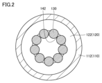
- FIG. 2 is a cross-sectional view taken along line II-II in FIG. 1.
- connecting member 200 and bolt 200A are not shown in FIG. 2.
- the up-down direction in FIG. 1 may be referred to as the "vertical direction” or "first direction”
- the left-right direction in FIG. 1 or the direction perpendicular to the paper surface may be referred to as the "horizontal direction” or "second direction.”
- the positioning and fixing device includes a fluid pressure cylinder 100 fixed to a base body 1, and a connecting member 200 attached to a fixing object 2 by a bolt 200A.
- the positioning and fixing device attracts and fixes the fixed object 2 to the first surface 10, which serves as the reference seat surface (reference surface) of the base body 1.
- the fixed object 2 comes into contact with the first surface 10 of the base body 1, making it possible to position the fixed object 2 relative to the base body 1 in the vertical direction.
- Examples of the fixed object 2 include a work pallet on which a workpiece to be cut is attached, or a mold, but the fixed object 2 in this technology is not limited to these.
- the fluid pressure cylinder 100 includes a cylinder body 110, a piston member 120, an engagement member 130, a rod member 140, a biasing member 150, and a stopper 160.
- the cylinder body 110 includes a large diameter portion 111, a small diameter portion 112, a hole portion 113, and a step surface 114.
- the large diameter portion 111 protrudes vertically (in the first direction) from the second surface 20 (rear surface) of the base body 1.
- the large diameter portion 111 has a larger outer diameter than the small diameter portion 112.
- the small diameter portion 112 is embedded in the base body 1. More specifically, the small diameter portion 112 is pressed into the insertion hole 30 of the base body 1 from the second surface 20 side. The first surface 10 of the base body 1 and the fixed object 2 come into contact in the area adjacent to the small diameter portion 112 of the cylinder body 110.
- the hole 113 is formed on the upper surface of the small diameter portion 112 so as to face the object to be fixed 2.
- the inner circumferential surface of the hole 113 abuts against the outer circumferential surface 210 of the connecting member 200.
- the hole 113 of the cylinder body 110 abuts against the outer circumferential surface 210 of the connecting member 200, making it possible to position the object to be fixed 2 relative to the base body 1 in the horizontal direction (second direction).
- the positioning in the horizontal direction may be positioning in both the left-right direction in FIG. 1 and the direction perpendicular to the paper surface, or may be positioning in only one of the above two directions. Furthermore, positioning in the horizontal direction (second direction) is not essential in this technology, and the positioning and fixing device may only perform positioning in the vertical direction (first direction).
- the step surface 114 is formed between the large diameter portion 111 and the small diameter portion 112.
- the step surface 114 abuts against the second surface 20 of the base body 1.
- the cylinder body 110 defines a cylinder chamber 110A (first chamber) and a cylinder chamber 110B (second chamber).
- the cylinder chambers 110A and 110B are partitioned by a piston member 120.
- the cylinder chambers 110A and 110B are formed in the large diameter portion 111 of the cylinder body 110.
- the piston member 120 is fitted into the large diameter portion 111 of the cylinder body 110.
- the piston member 120 is an annular member, and the rod member 140 is fitted into its inner periphery.
- the piston member 120 can be driven to reciprocate vertically by the pressure of the working medium (typically working air, but not limited to this, and may be working oil) supplied to and discharged from the cylinder chambers 110A and 110B.
- the working medium typically working air, but not limited to this, and may be working oil
- the piston member 120 includes a first portion 121 that fits into the large diameter portion 111 of the cylinder body 110, and a second portion 122 that fits into the small diameter portion 112 of the cylinder body 110. Between the first portion 121 and the second portion 122, a through hole 123 is formed that extends from the internal space 110C formed on the inner periphery of the piston member 120 to the cylinder chamber 110B formed on the outer periphery of the piston member 120.
- the engaging device 130 engages with the outer peripheral surface of the connecting member 200 and drives the connecting member 200 vertically (in the opposite direction to the piston member 120) while moving horizontally in accordance with the vertical reciprocating motion of the piston member 120.
- the engaging device 130 is provided on the small diameter portion 112 of the cylinder body 110.
- the engaging device 130 includes a number of steel balls arranged in a line around the cylinder body 110.
- the connecting member 200 includes engaging recesses 220 formed so that the steel balls can come into contact with each other.
- the engaging recesses 220 are formed over the entire circumferential direction of the connecting member 200 such that the outer circumferential surface 210 of the connecting member 200 is recessed radially inward.
- the rod member 140 is fixed to the cylinder body 110.
- the rod member 140 fits into the inner periphery of the piston member 120.
- the rod member 140 is formed with air passages 140A, 140B (working medium passages) that can supply air (working medium) from the inner periphery of the piston member 120 to the cylinder chambers 110A, 110B.
- the air passage 140A communicates with the cylinder chamber 110A.
- the through hole 123 formed in the piston member 120 communicates between the internal space 110C, which communicates with the air passage 140B, and the cylinder chamber 110B. As a result, the air passage 140B communicates with the cylinder chamber 110B.
- the air passages 140A, 140B are supplied with working air from below in the vertical direction.
- the air passages 140A, 140B have a portion that extends vertically from the input port and a portion that extends radially or diagonally to reach the outer periphery of the rod member 140.
- the input port of the air passages 140A, 140B is formed on the underside of the rod member 140, and its center is located in an area that overlaps with the engaging device 130 when viewed from the vertical direction (first direction), or in an area that is more inward than the engaging device 130.
- the working air supplied to the air passages 140A, 140B is supplied to the cylinder chambers 110A, 110B that reach an area more outward than the engaging device 130 when viewed from the vertical direction (first direction).
- the tip side of the rod member 140 is provided with a holding portion 141 that holds the engaging device 130 provided on the small diameter portion 112 of the cylinder body 110, and a recess 142 that receives the tip side of the connecting member 200.
- the biasing member 150 is housed in the cylinder chamber 110A on the lock side (clamp side).
- the biasing member 150 biases the piston member 120 vertically upward. In other words, the biasing member 150 biases the piston member 120 in the direction in which the fixed object 2 is fixed. This allows the fixed object 2 to remain positioned and fixed even if the supply of air pressure is interrupted.
- the stopper 160 is provided to fix the rod member 140 to the cylinder body 110.
- the stopper 160 restricts the displacement of the rod member 140 relative to the cylinder body 110.
- Sealing members 171, 172, 173, 174, and 175 are provided inside the cylinder body 110.
- the sealing member 171 is provided at the sliding portion between the large diameter portion 111 of the cylinder body 110 and the first part 121 of the piston member 120.
- the sealing member 172 is provided at the sliding portion between the small diameter portion 112 of the cylinder body 110 and the second part 122 of the piston member 120.
- the sealing member 173 is provided at the fitting portion between the rod member 140 and the large diameter portion 111 of the cylinder body 110.
- the sealing members 174 and 175 are each provided at the sliding portion between the inner surface of the piston member 120 and the rod member 140.
- the sealing member 171 seals between the cylinder chambers 110A and 110B.
- the sealing member 172 seals between the cylinder chamber 110B and the outside of the cylinder body 110.
- the seal member 173 seals between the cylinder chamber 110A and the outside of the cylinder body 110.
- the seal member 174 seals between the cylinder chamber 110A and the internal space 110C.
- the seal member 175 seals between the internal space 110C and the outside of the cylinder body 110.
- the seal members 171, 172, 173, 174, and 175 are, for example, O-rings.
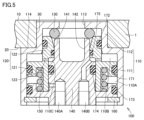
- Figure 3 is an enlarged view of the area around the engaging device 130.
- the second portion 122 of the piston member 120 is formed with a tapered surface 122A that slopes radially outward as it approaches the fixed object 2
- the holding portion 141 of the rod member 140 is formed with a tip surface 141A that slopes in the opposite direction to the tapered surface 122A of the piston member 120.
- the piston member 120 When air pressure is supplied to the cylinder chamber 110A, the piston member 120 is driven upward (towards the small diameter portion 112 of the cylinder body 110). When the piston member 120 is driven upward, the engaging member 130 held by the holding portion 141 of the rod member 140 is pressed radially inward of the connecting member 200 by the tapered surface 122A. The engaging member 130 pressed radially inward engages with the engaging recess 220 of the connecting member 200, driving the connecting member 200 vertically downward.
- the object to be fixed 2 is pushed downward.
- the piston member 120 is driven in a direction approaching the object to be fixed 2, and the engaging member 130 of the fluid pressure cylinder 100 is engaged with the engaging recess 220 of the connecting member 200, thereby fixing the object to be fixed 2 to the base body 1.
- the object to be fixed 2 is pushed down until it abuts against the first surface 10 of the base body 1.
- the first surface 10 realizes the positioning of the object to be fixed 2 in the vertical direction (first direction).
- the connecting member 200 When the connecting member 200 is driven downward, the outer circumferential surface 210 of the connecting member 200 engages with the hole 113 of the cylinder body 110. Therefore, the connecting member 200 descends while being guided by the hole 113 of the cylinder body 110. This achieves positioning of the fixed object 2 in the horizontal direction (second direction).
- Figures 4 and 5 are cross-sectional views showing the above-mentioned positioning and fixing device in an unclamped state ( Figure 4 shows the fixed object 2 and the connecting member 200, and Figure 5 shows the base body 1 and the fluid pressure cylinder 100).
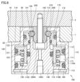
- FIG. 6 is a cross-sectional view showing a clamped state of a positioning and fixing device according to a modified example.
- the mounting direction of the bolt 200A for fixing the connecting member 200 to the fixed object 2 is different from the examples of FIG. 1 to FIG. 5.
- the above-mentioned air passages 140A, 140B (working medium passages) are formed in the rod member 140.
- an air passage 140C is formed that extends from the lower end of the rod member 140 to the recess 142.
- the inside of the cylinder body 110 can be cleaned by air (blow air) supplied to the recess 142 from the air passage 140C.
- air blow air
- detecting the air pressure in the air passage 140C it is also possible to detect whether the fixed object 2 is in close contact with the base body 1.
- air passages 140A, 140B are provided in the rod member 140 that is fitted to the inner periphery of the piston member 120, and the operating air is supplied from the inner periphery of the cylinder chambers 110A, 110B, allowing the operating air to be supplied and discharged from the piping connected below the fluid pressure cylinder 100, making it possible to make the entire mechanism smaller than when an air passage is formed in the base body 1.
- the engaging device 130 that drives the connecting member 200 is provided on the small diameter portion 112 of the cylinder body 110, the small diameter portion 112 is pressed into the insertion hole 30 of the base body 1, and the large diameter portion 111 protrudes from the second surface 20 side of the base body 1, making it possible to miniaturize the entire mechanism in both the vertical and horizontal directions.
- the cylinder body 110 can withstand the external force acting on the fixed object 2, making it possible to miniaturize the entire mechanism while maintaining the clamping force.
Landscapes
- Engineering & Computer Science (AREA)
- Mechanical Engineering (AREA)
- Jigs For Machine Tools (AREA)
- Actuator (AREA)
Abstract
シリンダ本体は、ベース体に埋設される小径部と、ベース体における第1面と反対側の第2面側から第1の方向に突出し、小径部よりも大きな外径を有する大径部とを含み、係合具はシリンダ本体の小径部に設けられ、ピストン部材を往復動させるシリンダ室がシリンダ本体の大径部に形成され、ピストン部材の内周側からシリンダ室に作動媒体を供給可能な作動媒体通路がロッド部材に形成され、係合具を介して連結部材を第1の方向に駆動することにより、固定対象物をベース体の第1面に当接させて第1の方向の位置決めを行う。
Description
本技術は、位置決め固定装置に関する。
固定対象物をベース体に対して位置決めした上で固定することが可能な位置決め固定装置が従来から知られている。本技術に対する背景技術として、下記の特許文献1ないし6に記載のものが挙げられる。
位置決め固定の機能を維持しながら装置をさらに小型化することが要請されている。従来の位置決め固定装置には、小型化の観点からさらなる改良の余地がある。
本技術の目的は、小型化された位置決め固定装置を提供することにある。
本技術は、1つの態様において、以下の位置決め固定装置を提供し得る。
[1]固定対象物をベース体の第1面に引き付けて固定するとともに、固定対象物をベース体に対して位置決めすることが可能な位置決め固定装置であって、ベース体に固定された流体圧シリンダと、外周面を有し、固定対象物に取付け可能な連結部材とを備え、流体圧シリンダは、シリンダ本体と、シリンダ本体に対して第1の方向に往復動可能な環状のピストン部材と、連結部材の外周面に係合し、ピストン部材の往復動に伴って連結部材を第1の方向に駆動する係合具と、シリンダ本体に固定され、ピストン部材の内周側に嵌合するロッド部材とを含み、シリンダ本体は、ベース体に埋設される小径部と、ベース体における第1面と反対側の第2面側から第1の方向に突出し、小径部よりも大きな外径を有する大径部とを含み、係合具はシリンダ本体の小径部に設けられ、ピストン部材を往復動させるシリンダ室がシリンダ本体の大径部に形成され、ピストン部材の内周側からシリンダ室に作動媒体を供給可能な作動媒体通路がロッド部材に形成され、係合具を介して連結部材を第1の方向に駆動することにより、固定対象物をベース体の第1面に当接させて第1の方向の位置決めを行う、位置決め固定装置。
[2]シリンダ本体は、連結部材の外周面と当接する内周面を有する孔部をさらに含み、連結部材の外周面を孔部の内周面に当接させて第1の方向に直交する第2の方向の位置決めを行う、[1]に記載の位置決め固定装置。
[3]ベース体は嵌入孔を有し、シリンダ本体の小径部は、第2面側から嵌入孔に圧入される、[1]または[2]に記載の位置決め固定装置。
[4]シリンダ本体における小径部と大径部との間に段差面が形成され、段差面はベース体の第2面に当接する、[1]から[3]のいずれか1項に記載の位置決め固定装置。
[5]ベース体は、第1面における小径部に隣接する領域において固定対象物と当接する、[1]から[4]のいずれか1項に記載の位置決め固定装置。
[6]ピストン部材は、シリンダ本体の大径部をベース体から遠い第1室とベース体に近い第2室とに区画し、ピストン部材の内周側から外周側に達し、作動媒体通路と第2室とを連通させる貫通孔がピストン部材に形成される、[1]から[5]のいずれか1項に記載の位置決め固定装置。
[7]ピストン部材は、シリンダ本体の大径部に嵌合される第1部分と、シリンダ本体の小径部に嵌合される第2部分とを含み、第1部分と第2部分との間に貫通孔が形成される、[6]に記載の位置決め固定装置。
[8]ロッド部材は、シリンダ本体の小径部に設けられた係合具を保持する保持部を含む、[1]から[7]のいずれか1項に記載の位置決め固定装置。
[9]係合具は、シリンダ本体の周方向に並ぶように設けられた複数の鋼球を含み、連結部材は、複数の鋼球が各々接触可能に形成された係合凹部を含む、[1]から[8]のいずれか1項に記載の位置決め固定装置。
[10]ピストン部材を固定対象物に接近する方向へ駆動し、複数の鋼球を係合凹部に各々係合させることによって固定対象物をベース体に位置決め固定し、ピストン部材を固定対象物から離間する方向へ駆動し、複数の鋼球を係合凹部から各々係合解除させることによって固定対象物をベース体から固定解除する、[9]に記載の位置決め固定装置。
[11]ロッド部材は、連結部材の先端側を受け入れる凹部を有する、[1]から[10]のいずれか1項に記載の位置決め固定装置。
[12]シリンダ室に収納され、固定対象物が固定される方向にピストン部材を付勢する付勢部材をさらに備えた、[1]から[11]のいずれか1項に記載の位置決め固定装置。
本技術によれば、小型化された位置決め固定装置を得ることができる。
以下に、本技術の実施の形態について説明する。なお、同一または相当する部分に同一の参照符号を付し、その説明を繰返さない場合がある。
なお、以下に説明する実施の形態において、個数、量などに言及する場合、特に記載がある場合を除き、本技術の範囲は必ずしもその個数、量などに限定されない。また、以下の実施の形態において、各々の構成要素は、特に記載がある場合を除き、本技術にとって必ずしも必須のものではない。また、本技術は、本実施の形態において言及する作用効果を必ずしもすべて奏するものに限定されない。
なお、本明細書において、「備える(comprise)」および「含む(include)」、「有する(have)」の記載は、オープンエンド形式である。すなわち、ある構成を含む場合に、当該構成以外の他の構成を含んでもよいし、含まなくてもよい。
また、本明細書において幾何学的な文言および位置・方向関係を表す文言、たとえば「平行」、「直交」、「斜め45°」、「同軸」、「沿って」などの文言が用いられる場合、それらの文言は、製造誤差ないし若干の変動を許容する。本明細書において「上側」、「下側」などの相対的な位置関係を表す文言が用いられる場合、それらの文言は、1つの状態における相対的な位置関係を示すものとして用いられるものであり、各機構の設置方向(たとえば機構全体を上下反転させる等)により、相対的な位置関係は反転ないし任意の角度に回動し得る。
図1は、1つの実施の形態に係る位置決め固定装置のクランプ状態を示す断面図であり、図2は、図1におけるII-II断面図である。なお、図2においては、図示の便宜上、連結部材200およびボルト200Aを示していない。以下、図1中の上下方向を「鉛直方向」ないし「第1の方向」と称し、図1中の左右方向ないし紙面に垂直な方向を「水平方向」ないし「第2の方向」と称する場合がある。
本実施の形態に係る位置決め固定装置は、図1,図2に示すように、ベース体1に固定された流体圧シリンダ100と、ボルト200Aにより固定対象物2に取付けられた連結部材200とを含む。
位置決め固定装置は、固定対象物2をベース体1の基準座面(基準面)としての第1面10に引き付けて固定する。固定対象物2とベース体1の第1面10とが当接することにより、鉛直方向において、固定対象物2をベース体1に対して位置決めすることが可能である。
固定対象物2の例としては、たとえば、切削加工に供するワークを取り付けるワークパレット、または金型などが挙げられるが、本技術における固定対象物2はこれらに限定されない。
図1に示すように、流体圧シリンダ100は、シリンダ本体110と、ピストン部材120と、係合具130と、ロッド部材140と、付勢部材150と、止め具160とを含む。
シリンダ本体110は、大径部111と、小径部112と、孔部113と、段差面114とを含む。
大径部111は、ベース体1の第2面20(裏面)側から鉛直方向(第1の方向)に突出する。大径部111は、小径部112よりも大きな外径を有する。
小径部112は、ベース体1に埋設される。より具体的には、小径部112は、第2面20側からベース体1の嵌入孔30に圧入される。シリンダ本体110の小径部112に隣接する領域においてベース体1の第1面10と固定対象物2とが当接する。
孔部113は、固定対象物2に対向するように、小径部112の上面に形成される。孔部113の内周面は、連結部材200の外周面210と当接する。シリンダ本体110の孔部113と連結部材200の外周面210とが当接することにより、水平方向(第2の方向)において、固定対象物2をベース体1に対して位置決めすることが可能である。水平方向の位置決めは、図1中の左右方向および紙面に垂直な方向の両方向の位置決めであってもよいし、上記二方向のうち一方向のみの位置決めであってもよい。また、本技術において水平方向(第2の方向)の位置決めは必須ではなく、鉛直方向(第1の方向)の位置決めのみを行う位置決め固定装置であってもよい。
段差面114は、大径部111と小径部112との間に形成される。段差面114は、ベース体1の第2面20に当接する。ベース体1に固定された固定対象物2に外力が作用したとき、その外力は、連結部材200および係合具130を介してシリンダ本体110に伝達される。シリンダ本体110に伝達された外力は、段差面114を介してベース体1に伝達され得る。このように、段差面114を介して固定対象物2に作用する力をベース体1に伝達することができるため、特に、固定対象物2をベース体1から引き離す方向の外力が作用したとき、その外力をベース体1により受け止めて、固定対象物2の意図しない位置ずれ等を抑制することができる。
シリンダ本体110の内部には、シリンダ室110A(第1室)およびシリンダ室110B(第2室)とが形成されている。シリンダ室110A,110Bは、ピストン部材120により区画されている。シリンダ室110A,110Bは、シリンダ本体110の大径部111に形成されている。
固定対象物2を固定(クランプ)するときは、シリンダ室110Aに作動圧が供給される。固定対象物2の固定を解除(アンクランプ)するときは、シリンダ室110Bに作動圧が供給される。
ピストン部材120は、シリンダ本体110の大径部111に嵌合される。ピストン部材120は環状の部材であり、その内周側にロッド部材140が嵌合される。ピストン部材120は、シリンダ室110A,110Bに対して給排される作動媒体(典型的には作動エアであるが、これに限定されず、作動油であってもよい。)の圧力によって鉛直方向に往復駆動され得る。
ピストン部材120は、シリンダ本体110の大径部111に嵌合される第1部分121と、シリンダ本体110の小径部112に嵌合される第2部分122とを含む。第1部分121と第2部分122との間には、ピストン部材120の内周側に形成された内部空間110Cからピストン部材120の外周側に形成されたシリンダ室110Bに達する貫通孔123が形成されている。
係合具130は、連結部材200の外周面に係合し、ピストン部材120の鉛直方向の往復動に伴って水平方向に動きながら連結部材200を鉛直方向(ピストン部材120とは逆の方向)に駆動する。係合具130は、シリンダ本体110の小径部112に設けられる。
図2に示すように、係合具130は、シリンダ本体110の周方向に並ぶように設けられた複数の鋼球を含む。連結部材200は、複数の鋼球が各々接触可能に形成された係合凹部220を含む。係合凹部220は、連結部材200の周方向全体にわたって、連結部材200の外周面210が径方向内方に凹むように形成される。
再び図1を参照して、ロッド部材140は、シリンダ本体110に固定される。ロッド部材140は、ピストン部材120の内周側に嵌合する。ロッド部材140には、ピストン部材120の内周側からシリンダ室110A,110Bにエア(作動媒体)を供給可能なエア通路140A,140B(作動媒体通路)が形成されている。エア通路140Aは、シリンダ室110Aと連通する。ピストン部材120に形成された貫通孔123は、エア通路140Bと連通する内部空間110Cとシリンダ室110Bとを連通させる。これにより、エア通路140Bは、シリンダ室110Bと連通する。
エア通路140A,140Bには、鉛直方向下方から作動エアが供給される。エア通路140A,140Bは、入力ポートから鉛直方向に延びる部分と、径方向または斜め方向に延びてロッド部材140の外周に達する部分とを有する。エア通路140A,140Bの入力ポートは、ロッド部材140の下面に形成され、その中心は、鉛直方向(第1の方向)からみて係合具130と重なる領域、または係合具130よりも内周側の領域に位置する。エア通路140A,140Bに供給された作動エアは、鉛直方向(第1の方向)からみて係合具130よりも外周側の領域に達するシリンダ室110A,110Bに供給される。
ロッド部材140の先端側には、シリンダ本体110の小径部112に設けられた係合具130を保持する保持部141と、連結部材200の先端側を受け入れる凹部142とが設けられている。
付勢部材150は、ロック側(クランプ側)のシリンダ室110Aに収納される。付勢部材150は、ピストン部材120を鉛直方向上方に付勢する。すなわち、付勢部材150は、固定対象物2が固定される方向にピストン部材120を付勢する。これにより、エア圧の供給が中断された場合にも、固定対象物2が位置決め固定された状態を維持することができる。
止め具160は、シリンダ本体110に対してロッド部材140を固定するために設けられる。止め具160により、シリンダ本体110に対するロッド部材140の変位が規制される。
シール部材171,172,173,174,175がシリンダ本体110の内部に設けられる。シール部材171は、シリンダ本体110の大径部111とピストン部材120の第1部分121との摺動部分に設けられる。シール部材172は、シリンダ本体110の小径部112とピストン部材120の第2部分122との摺動部分に設けられる。シール部材173は、ロッド部材140とシリンダ本体110の大径部111との嵌合部に設けられる。シール部材174,175は、各々、ピストン部材120の内周面とロッド部材140との摺動部分に設けられる。シール部材171は、シリンダ室110A,110B間をシールする。シール部材172は、シリンダ室110Bとシリンダ本体110の外部との間をシールする。シール部材173は、シリンダ室110Aとシリンダ本体110の外部との間をシールする。シール部材174は、シリンダ室110Aと内部空間110Cとの間をシールする。シール部材175は、内部空間110Cとシリンダ本体110の外部との間をシールする。シール部材171,172,173,174,175は、たとえばOリングからなる。
上述のとおり、固定対象物2をベース体1に位置決め固定するときは、シリンダ室110Aにエア圧を供給し、ピストン部材120を固定対象物2に接近する方向へ駆動し、係合具130を連結部材200の係合凹部220に係合させる。これにより、係合具130を介して連結部材200が鉛直方向下方に駆動される。この結果、固定対象物2がベース体1の第1面10に当接して鉛直方向の位置決めが行われ、連結部材200の外周面210がシリンダ本体110の孔部113の内周面に当接して水平方向の位置決めが行われる。
図3は、係合具130周辺の拡大図である。図3に示すように、ピストン部材120の第2部分122には、固定対象物2に近づくにつれて径方向外方に傾斜するテーパ面122Aが形成され、ロッド部材140の保持部141には、ピストン部材120のテーパ面122Aとは逆向きに傾斜する先端面141Aが形成される。
シリンダ室110Aにエア圧が供給されると、ピストン部材120が上方側(シリンダ本体110の小径部112側)に駆動される。ピストン部材120が上方側に駆動されると、ロッド部材140の保持部141に保持されていた係合具130が、テーパ面122Aによって連結部材200の径方向内側に押圧される。径方向内側に押圧された係合具130は、連結部材200の係合凹部220に係合し、連結部材200を鉛直方向下方に駆動する。
これにより、固定対象物2が下方に押し下げられる。すなわち、ピストン部材120を固定対象物2に近づく方向へ駆動し、流体圧シリンダ100の係合具130を連結部材200の係合凹部220に係合させることによって固定対象物2をベース体1に固定する。
固定対象物2は、ベース体1の第1面10に当接するまで押し下げられる。第1面10により、固定対象物2の鉛直方向(第1の方向)の位置決めが実現される。
連結部材200が下方に駆動されるとき、連結部材200の外周面210がシリンダ本体110の孔部113に係合する。したがって、連結部材200は、シリンダ本体110の孔部113によってガイドされながら下降する。これにより、固定対象物2の水平方向(第2の方向)の位置決めが実現される。
図4,図5は、上述の位置決め固定装置のアンクランプ状態を示す断面図(図4は固定対象物2および連結部材200、図5はベース体1および流体圧シリンダ100)を示す断面図である。
固定対象物2の位置決め固定を解除するときは、シリンダ室110Bにエア圧を供給し、ピストン部材120を固定対象物2から離間する方向へ駆動し、係合具130と連結部材200の係合凹部220との係合を解除する。これにより、図4,図5に示すように、固定対象物2がベース体1から固定解除され、両者が分離可能となる。
図6は、変形例に係る位置決め固定装置のクランプ状態を示す断面図である。図6の例では、連結部材200を固定対象物2に固定するためのボルト200Aの取付方向が図1から図5の例とは異なる。
図6には示されていないが、本変形例においても、上述したエア通路140A,140B(作動媒体通路)がロッド部材140に形成されている。また、図6に示すように、ロッド部材140の下端から凹部142に達するエア通路140Cが形成されている。
エア通路140Cから凹部142に供給されるエア(ブローエア)により、シリンダ本体110内部の清掃を行うことができる。また、エア通路140Cのエア圧を検知することにより、固定対象物2のベース体1への密着の検知を行うことも可能である。
本実施の形態に係る位置決め固定装置においては、ピストン部材120の内周側に嵌合されるロッド部材140にエア通路140A,140Bを設け、シリンダ室110A,110Bの内周側から作動エアを供給することにより、流体圧シリンダ100の下方に接続された配管から作動エアの給排を行うことができるので、ベース体1にエア通路を形成する場合と比較して、機構全体を小型化することが可能となる。
ここで、連結部材200を駆動する係合具130をシリンダ本体110の小径部112に設け、小径部112をベース体1の嵌入孔30に圧入し、大径部111をベース体1の第2面20側から突出させることにより、鉛直方向および水平方向において機構全体を小型化することが可能となる。
また、ベース体1と固定対象物2とを直接密着させて位置決め固定することにより、鉛直方向において機構全体を小型化することが可能である。
また、ピストン部材120を往復動させるシリンダ室110A,110Bをシリンダ本体の大径部111に形成することにより、シリンダ面積を確保しながら機構全体の小型化を図ることができる。
また、大径部111と小径部112との間の段差面114をベース体1の第2面20に当接させることにより、固定対象物2に作用する外力をシリンダ本体110により受け止めることができるので、クランプ力を維持しながら機構全体の小型化を図ることができる。
以上、本技術の実施の形態について説明したが、今回開示された実施の形態はすべての点で例示であって制限的なものではないと考えられるべきである。本技術の範囲は請求の範囲によって示され、請求の範囲と均等の意味および範囲内でのすべての変更が含まれることが意図される。
1 ベース体、2 固定対象物、10 第1面、20 第2面、30 嵌入孔、100 流体圧シリンダ、110 シリンダ本体、110A,110B シリンダ室、110C 内部空間、111 大径部、112 小径部、113 孔部、114 段差面、120 ピストン部材、121 第1部分、122 第2部分、122A テーパ面、123 貫通孔、130 係合具、140 ロッド部材、140A,140B,140C エア通路、141 保持部、141A 先端面、142 凹部、150 付勢部材、160 止め具、171,172,173,174,175 シール部材、200 連結部材、200A ボルト、210 外周面、220 係合凹部。
Claims (12)
- 固定対象物をベース体の第1面に引き付けて固定するとともに、前記固定対象物を前記ベース体に対して位置決めすることが可能な位置決め固定装置であって、
前記ベース体に固定された流体圧シリンダと、
外周面を有し、前記固定対象物に取付け可能な連結部材とを備え、
前記流体圧シリンダは、シリンダ本体と、前記シリンダ本体に対して第1の方向に往復動可能な環状のピストン部材と、前記連結部材の前記外周面に係合し、前記ピストン部材の往復動に伴って前記連結部材を前記第1の方向に駆動する係合具と、前記シリンダ本体に固定され、前記ピストン部材の内周側に嵌合するロッド部材とを含み、
前記シリンダ本体は、前記ベース体に埋設される小径部と、前記ベース体における前記第1面と反対側の第2面側から前記第1の方向に突出し、前記小径部よりも大きな外径を有する大径部とを含み、
前記係合具は前記シリンダ本体の前記小径部に設けられ、
前記ピストン部材を往復動させるシリンダ室が前記シリンダ本体の前記大径部に形成され、
前記ピストン部材の内周側から前記シリンダ室に作動媒体を供給可能な作動媒体通路が前記ロッド部材に形成され、
前記係合具を介して前記連結部材を前記第1の方向に駆動することにより、前記固定対象物を前記ベース体の前記第1面に当接させて前記第1の方向の位置決めを行う、位置決め固定装置。 - 前記シリンダ本体は、前記連結部材の前記外周面と当接する内周面を有する孔部をさらに含み、
前記連結部材の前記外周面を前記孔部の前記内周面に当接させて前記第1の方向に直交する第2の方向の位置決めを行う、請求項1に記載の位置決め固定装置。 - 前記ベース体は嵌入孔を有し、
前記シリンダ本体の前記小径部は、前記第2面側から前記嵌入孔に圧入される、請求項1または請求項2に記載の位置決め固定装置。 - 前記シリンダ本体における前記小径部と前記大径部との間に段差面が形成され、前記段差面は前記ベース体の前記第2面に当接する、請求項1から請求項3のいずれか1項に記載の位置決め固定装置。
- 前記ベース体は、前記第1面における前記小径部に隣接する領域において前記固定対象物と当接する、請求項1から請求項4のいずれか1項に記載の位置決め固定装置。
- 前記ピストン部材は、前記シリンダ本体の前記大径部を前記ベース体から遠い第1室と前記ベース体に近い第2室とに区画し、
前記ピストン部材の内周側から外周側に達し、前記作動媒体通路と前記第2室とを連通させる貫通孔が前記ピストン部材に形成される、請求項1から請求項5のいずれか1項に記載の位置決め固定装置。 - 前記ピストン部材は、前記シリンダ本体の前記大径部に嵌合される第1部分と、前記シリンダ本体の前記小径部に嵌合される第2部分とを含み、前記第1部分と前記第2部分との間に前記貫通孔が形成される、請求項6に記載の位置決め固定装置。
- 前記ロッド部材は、前記シリンダ本体の前記小径部に設けられた前記係合具を保持する保持部を含む、請求項1から請求項7のいずれか1項に記載の位置決め固定装置。
- 前記係合具は、前記シリンダ本体の周方向に並ぶように設けられた複数の鋼球を含み、
前記連結部材は、前記複数の鋼球が各々接触可能に形成された係合凹部を含む、請求項1から請求項8のいずれか1項に記載の位置決め固定装置。 - 前記ピストン部材を前記固定対象物に接近する方向へ駆動し、前記複数の鋼球を前記係合凹部に各々係合させることによって前記固定対象物を前記ベース体に位置決め固定し、
前記ピストン部材を前記固定対象物から離間する方向へ駆動し、前記複数の鋼球を前記係合凹部から各々係合解除させることによって前記固定対象物を前記ベース体から固定解除する、請求項9に記載の位置決め固定装置。 - 前記ロッド部材は、前記連結部材の先端側を受け入れる凹部を有する、請求項1から請求項10のいずれか1項に記載の位置決め固定装置。
- 前記シリンダ室に収納され、前記固定対象物が固定される方向に前記ピストン部材を付勢する付勢部材をさらに備えた、請求項1から請求項11のいずれか1項に記載の位置決め固定装置。
Priority Applications (1)
| Application Number | Priority Date | Filing Date | Title |
|---|---|---|---|
| DE112024001808.4T DE112024001808T5 (de) | 2023-06-05 | 2024-05-07 | Positionier- und Fixiervorrichtung |
Applications Claiming Priority (2)
| Application Number | Priority Date | Filing Date | Title |
|---|---|---|---|
| JP2023092298A JP2024174464A (ja) | 2023-06-05 | 2023-06-05 | 位置決め固定装置 |
| JP2023-092298 | 2023-06-05 |
Publications (1)
| Publication Number | Publication Date |
|---|---|
| WO2024252829A1 true WO2024252829A1 (ja) | 2024-12-12 |
Family
ID=93795268
Family Applications (1)
| Application Number | Title | Priority Date | Filing Date |
|---|---|---|---|
| PCT/JP2024/016940 Ceased WO2024252829A1 (ja) | 2023-06-05 | 2024-05-07 | 位置決め固定装置 |
Country Status (3)
| Country | Link |
|---|---|
| JP (1) | JP2024174464A (ja) |
| DE (1) | DE112024001808T5 (ja) |
| WO (1) | WO2024252829A1 (ja) |
Citations (3)
| Publication number | Priority date | Publication date | Assignee | Title |
|---|---|---|---|---|
| JPH09285925A (ja) * | 1996-04-23 | 1997-11-04 | Kosmek Ltd | クランプ装置 |
| US20070210501A1 (en) * | 2004-02-09 | 2007-09-13 | Zero-Point Systems Gunther Stark Gmbh | Quick-Action Clamping Cylinder With An Anti-Blocking Safety Device |
| WO2023053761A1 (ja) * | 2021-09-28 | 2023-04-06 | パスカルエンジニアリング株式会社 | 連結装置およびクランプ装置 |
Family Cites Families (4)
| Publication number | Priority date | Publication date | Assignee | Title |
|---|---|---|---|---|
| ITTV20120129A1 (it) | 2012-07-11 | 2014-01-12 | Almerino Canuto | Dispositivo di compensazione del disassamento in sistemi di bloccaggio automatici |
| JP6863582B2 (ja) | 2017-07-10 | 2021-04-21 | パスカルエンジニアリング株式会社 | ロボットアームカップリング装置 |
| DE202018104109U1 (de) | 2018-07-17 | 2018-07-23 | Andreas Maier Gmbh & Co. Kg | Spannvorrichtung |
| JP7122748B2 (ja) | 2018-10-30 | 2022-08-22 | パスカルエンジニアリング株式会社 | 位置決め固定装置 |
-
2023
- 2023-06-05 JP JP2023092298A patent/JP2024174464A/ja active Pending
-
2024
- 2024-05-07 WO PCT/JP2024/016940 patent/WO2024252829A1/ja not_active Ceased
- 2024-05-07 DE DE112024001808.4T patent/DE112024001808T5/de active Pending
Patent Citations (3)
| Publication number | Priority date | Publication date | Assignee | Title |
|---|---|---|---|---|
| JPH09285925A (ja) * | 1996-04-23 | 1997-11-04 | Kosmek Ltd | クランプ装置 |
| US20070210501A1 (en) * | 2004-02-09 | 2007-09-13 | Zero-Point Systems Gunther Stark Gmbh | Quick-Action Clamping Cylinder With An Anti-Blocking Safety Device |
| WO2023053761A1 (ja) * | 2021-09-28 | 2023-04-06 | パスカルエンジニアリング株式会社 | 連結装置およびクランプ装置 |
Also Published As
| Publication number | Publication date |
|---|---|
| DE112024001808T5 (de) | 2026-02-26 |
| JP2024174464A (ja) | 2024-12-17 |
Similar Documents
| Publication | Publication Date | Title |
|---|---|---|
| JP5750053B2 (ja) | クランプ装置 | |
| JP5779194B2 (ja) | 位置決め装置 | |
| JP6283219B2 (ja) | クランプ装置 | |
| WO2011108352A1 (ja) | クランプ装置 | |
| TWI655992B (zh) | 夾具裝置 | |
| JP2018118333A (ja) | 自動工具交換装置 | |
| TW201702491A (zh) | 流體壓力缸 | |
| KR102282818B1 (ko) | 파지 장치 | |
| CN100478127C (zh) | 定位装置和具有该定位装置的夹持系统 | |
| WO2024070395A1 (ja) | 部材交換装置 | |
| WO2024252829A1 (ja) | 位置決め固定装置 | |
| WO2023053761A1 (ja) | 連結装置およびクランプ装置 | |
| JP4877787B2 (ja) | 位置決め装置およびその装置を備えた位置決めシステム | |
| JP7774286B2 (ja) | クランプ装置 | |
| JP2005188670A (ja) | 締結装置 | |
| JP2023173257A (ja) | クランプ装置および回転支持装置 | |
| CN222972185U (zh) | 用于冲压工况的机器人工具快换装置 | |
| KR20180016577A (ko) | 유체압 실린더 | |
| WO2026053622A1 (ja) | 流体圧シリンダ | |
| JP2024033373A (ja) | 位置決め固定装置 | |
| JPH1151009A (ja) | 流体圧アクチュエータ |
Legal Events
| Date | Code | Title | Description |
|---|---|---|---|
| 121 | Ep: the epo has been informed by wipo that ep was designated in this application |
Ref document number: 24819066 Country of ref document: EP Kind code of ref document: A1 |
|
| WWE | Wipo information: entry into national phase |
Ref document number: 112024001808 Country of ref document: DE |
|
| WWP | Wipo information: published in national office |
Ref document number: 112024001808 Country of ref document: DE |