WO2024252803A1 - 回転電機 - Google Patents
回転電機 Download PDFInfo
- Publication number
- WO2024252803A1 WO2024252803A1 PCT/JP2024/015577 JP2024015577W WO2024252803A1 WO 2024252803 A1 WO2024252803 A1 WO 2024252803A1 JP 2024015577 W JP2024015577 W JP 2024015577W WO 2024252803 A1 WO2024252803 A1 WO 2024252803A1
- Authority
- WO
- WIPO (PCT)
- Prior art keywords
- bracket
- electric machine
- rotating electric
- frame
- stator
- Prior art date
- Legal status (The legal status is an assumption and is not a legal conclusion. Google has not performed a legal analysis and makes no representation as to the accuracy of the status listed.)
- Ceased
Links
Images









Classifications
-
- H—ELECTRICITY
- H02—GENERATION; CONVERSION OR DISTRIBUTION OF ELECTRIC POWER
- H02K—DYNAMO-ELECTRIC MACHINES
- H02K5/00—Casings; Enclosures; Supports
- H02K5/04—Casings or enclosures characterised by the shape, form or construction thereof
- H02K5/10—Casings or enclosures characterised by the shape, form or construction thereof with arrangements for protection from ingress, e.g. water or fingers
-
- H—ELECTRICITY
- H02—GENERATION; CONVERSION OR DISTRIBUTION OF ELECTRIC POWER
- H02K—DYNAMO-ELECTRIC MACHINES
- H02K5/00—Casings; Enclosures; Supports
- H02K5/04—Casings or enclosures characterised by the shape, form or construction thereof
- H02K5/22—Auxiliary parts of casings not covered by groups H02K5/06-H02K5/20, e.g. shaped to form connection boxes or terminal boxes
Definitions
- This disclosure relates to rotating electrical machines.
- Patent Document 1 discloses a structure example in which a rubber gasket is placed on the mating surfaces of parts.
- Patent Document 2 discloses a structure for preventing water from entering the motor and for draining water that does enter by some chance, in which a drain hole is installed that opens vertically downward when the motor is installed.
- Patent Document 1 has issues such as being difficult to control in dimensions and varying crushing loads due to the need to crush it before use, so it is necessary to ensure the dimensional precision, rigidity, and strength of the mating parts that come into contact with the gasket.
- This disclosure discloses technology to solve the problems described above, and aims to provide a rotating electric machine with a compact structure while ensuring waterproof performance.
- the rotating electric machine disclosed in the present disclosure includes: A rotating electric machine including a stator and a rotor that rotates with an outer circumferential surface facing an inner circumferential surface of the stator,
- the stator includes a cylindrical frame and a bracket that closes an opening at an axial end of the frame, At least one of the frame and the bracket at the fitting portion between the frame and the bracket has a drain groove recessed radially inward and extending circumferentially.
- the rotating electric machine disclosed in this disclosure can provide a rotating electric machine with a compact structure while ensuring waterproof performance.
- FIG. 1 is a cross-sectional view of a motor according to a first embodiment.
- 1 is a plan view of a bracket according to a first embodiment, as viewed from the axial Z- side.
- FIG. This is a cross-sectional view taken along line AA in FIG.
- FIG. 2 is a perspective view of a bracket according to the first embodiment.
- FIG. 2 is a perspective view of a stator according to the first embodiment.
- 2 is a cross-sectional view of a stator according to the first embodiment.
- FIG. 1 is an enlarged view of a main portion of a motor according to a first embodiment; 1 is an enlarged view of a main portion of a motor according to a first embodiment; 1 is a schematic cross-sectional view of a motor according to a first embodiment.
- FIG. 5 is a diagram showing a flow path of water that has entered the inside of the motor through a screw hole of the bracket in the first embodiment.
- FIG. 4 is a cross-sectional view showing another example of the motor according to the first embodiment.
- FIG. 13 is a diagram showing a fitting portion between a bracket and a stator according to a second embodiment; 13A and 13B are diagrams showing a fitting portion between a bracket and a stator according to a third embodiment; 13A and 13B are diagrams showing a fitting portion between a bracket and a stator according to a fourth embodiment;
- FIG. 13 is a perspective view of a stator according to a fifth embodiment.
- FIG. 13 is a perspective view showing the shape of a lead holder according to a fifth embodiment.
- FIG. 13 is a perspective view of a motor according to a fifth embodiment.
- FIG. 13 is an enlarged cross-sectional view of a main portion of a motor according to a fifth embodiment.
- 13 is a diagram showing a cross section of a motor in the vicinity of a drain outlet according to a fifth embodiment.
- FIG. FIG. 13 is a perspective view of a stator according to a sixth embodiment.
- FIG. 13 is a perspective view of a motor according to a sixth embodiment.
- FIG. 13 is an enlarged cross-sectional view of a main portion showing an example of a motor provided with a plurality of drain grooves.
- FIG. 13 is an enlarged cross-sectional view of a main portion showing an example of a motor provided with a plurality of drain grooves.
- FIG. 13 is an enlarged cross-sectional view of a main portion showing an example of a motor provided with a plurality of drain grooves.
- FIG. 13 is an enlarged view of a main portion of a motor according to a seventh embodiment.
- FIG. 25 is an enlarged view of a main part of FIG. 24 .
- Fig. 13 is an enlarged view of a main part of a motor according to embodiment 7.
- Fig. 14 is a view showing another example of the base.
- FIG. 23 is a perspective view showing yet another example of the base according to the seventh embodiment.
- 10A and 10B are diagrams showing another fixing method for the bracket according to the first embodiment, and diagrams showing the state before fixing.
- 13A and 13B are diagrams showing another fixing method for the bracket according to the first embodiment, and diagrams showing the bracket after fixing.
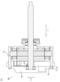
- FIG. 1 is a cross-sectional view of a motor 100 according to a first embodiment.
- the motor 100 which is a rotating electric machine, is installed horizontally and sideways, but as long as the tip of the shaft 11 is between vertically upward and horizontally, the positional relationship in which the water intrusion path described below is on the upper side of the motor 100 in the installed state and the drainage path is on the lower side of the motor 100 in the installed state is maintained, so that the waterproof effect described below is established.
- the axial direction of the motor 100 is the axial direction Z, the load side (right side of FIG.
- the motor 100 includes a stator 20, a rotor 10 that rotates with its outer circumferential surface facing the inner circumferential surface of the stator 20, a shaft 11 that supports the rotor 10, a bearing Br that supports the load side of the shaft 11, a counter-load side housing 30 that supports the counter-load side bearing Br, a board 40 that is disposed on the axial Z+ side of the counter-load side housing 30 and controls the current flowing through the coil 21 of the stator 20, a bracket 60 that is disposed on the outside of the board 40 in the axial Z direction via a heat dissipation sheet 50, and a lead wire WL that supplies power to the board 40.
- the heat dissipation sheet 50 is disposed to dissipate heat generated in the board 40 to the outside.
- the bracket 60 is also a lid that closes the opening 24Q at the end of the counter-load side of the resin frame 24 of the stator 20.
- the stator 20 has a coil 21 wound around a stator core 22 via an insulator 23, and the outer periphery is molded with molded resin to form a resin frame 24.
- the part of the resin frame 24 that holds the bearing at the load side end of the resin frame 24 is the load side housing 24L.
- the end of the resin frame 24 on the anti-load side is the first fitting portion 24K1 that fits with the outer periphery of the bracket 60.
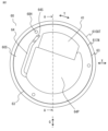
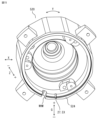
- FIG. 2 is a plan view of the bracket 60 as viewed from the axial Z-side.
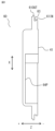
- FIG. 3 is a cross-sectional view taken along line AA of FIG.
- FIG. 4 is a perspective view of the bracket 60.
- the bracket 60 has a disk-like shape, and has an outer fitting portion 61OUT on its outer circumferential surface, which protrudes outward in the radial direction X like a flange and is fitted with the first fitting portion 24K1 of the resin frame 24.
- the bracket 60 also has an inner fitting portion 61IN on its outer circumferential surface, which is closer to the axial direction Z- side than the outer fitting portion 61OUT and protrudes outward in the radial direction X with a smaller diameter than the outer fitting portion 61OUT.
- a drainage groove 63 is formed between the outer fitting portion 61OUT and the inner fitting portion 61IN, which extends around the entire circumference of the bracket 60 in the circumferential direction Y and has a smaller diameter than the inner fitting portion 61IN, so as to be recessed inward in the radial direction X.
- the bracket 60 also has a flat board contact portion 41 that comes into contact with the board 40 via the heat dissipation sheet 50 to dissipate heat. If the bracket 60 is made of a metal such as an aluminum alloy or steel, the drainage groove 63 can be easily formed by turning. If the bracket 60 is made of a resin, it can be formed by molding using a sliding die or by turning after molding.
- Three screw holes 60H for fixing the bracket 60 with screws are opened in the axial Z direction radially inward from the minimum diameter portion of the drain groove 63.
- the end face 60S on the axial Z-side of the bracket 60 is provided with a drainage channel 64.
- the drainage channel 64 is recessed toward the axial Z+ side so as to extend from a starting point 64S on the inner side in the radial direction X below the screw hole 60H that is located on the uppermost G+ side (upper side in Figure 2) in the vertical direction G when the motor 100 is installed, to the lower G- side in the vertical direction G and inward in the radial direction X from the starting point 64S.
- the drainage channel 64 starts between the screw hole 60H, which is located at the uppermost G+ side in the vertical direction G, and the board contact portion 41, and extends further downward than the lower end of the board contact portion 41, and is connected to a water collection portion 64P formed on the end face 60S (inner surface) on the axial Z- side of the bracket 60, recessed toward the axial Z+ side (outside), and formed radially inward of the starting point 64S.
- the drainage channel 64 serves to guide the infiltrated water through the water collecting portion 64P to a drain outlet provided on the lower G- side in the vertical direction G, which will be described later.
- the drainage channel 64 is effective only when the screw hole 60H of the bracket 60 is located radially inward from the inner fitting portion 61IN, and is unnecessary when the screw hole 60H of the bracket 60 is located radially outward from the inner fitting portion 61IN.
- the drainage channel 64 is composed of an inclined groove 64K1 formed so that the depth of the groove gradually deepens toward the axial Z+ side from the starting point 64S toward the lower G-, and a guide groove 64K2 connected to the lower end portion 64KU of the inclined groove 64K1 and connected to the water collecting portion 64P at the same depth. That is, in the drainage channel 64, the bottom surface of the portion of the starting point 64S closest to the screw hole 60H of the bracket 60 is located on the most negative axial Z side, and as it moves away from the screw hole 60H of the bracket 60, the bottom surface of the inclined groove 64K1 constituting the drainage channel 64 inclines to the + axial Z side, and the depth of the inclined groove 64K1 in the axial Z direction increases.
- the lower end 64KU of the inclined groove 64K1 of the drainage channel 64 is connected to the upper end of the guide groove 64K2 of the drainage channel 64, which has the same depth over its entire length where the bottom surface is not inclined in the axial Z direction. This allows the water that enters from the screw hole 60H and flows downward to be collected by the Coanda effect.
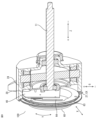
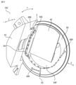
- FIG. 5 is a perspective view of the stator 20.
- FIG. 6 is a cross-sectional view of the stator 20.
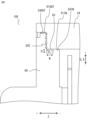
- 7 is an enlarged view of a main portion of the motor 100.
- the enlarged view shows the fitting portion between the bracket 60 and the resin frame 24.
- An outer fitting portion 24OUT having the same diameter as the outer fitting portion 61OUT of the bracket 60 is formed at the end portion on the axial Z+ side of the resin frame 24 of the stator 20, and an inner fitting portion 24IN having the same diameter as the inner fitting portion 61IN of the bracket 60 is formed at the axial Z- side of the outer fitting portion 24OUT, and these are fitted together when the bracket 60 is assembled to the stator 20.
- a countersunk portion 24Z recessed in an annular shape toward the axial Z- side is formed at the end portion on the anti-load side of the resin frame 24, and the outer wall surface of the countersunk portion 24Z in the radial direction X is the outer fitting portion 24OUT, and the wall surface on the axial Z- side of the countersunk portion 24Z is the inner fitting portion 24IN.
- the end of the countersunk portion 24Z on the lower G- side in the vertical direction G has a groove 27 which, when combined with a bracket 60, serves as the drain outlet EX and lead wire WL outlet shown in FIG. 1.
- the groove 27 is recessed in the axial Z- direction at the axial Z+ end of the resin frame 24, and the axial Z range of the groove 27 is from the axial Z+ side end to the axial Z- side of the bottom surface of the countersunk portion 24Z.
- multiple outlets for the drain outlet EX and lead wire WL may be provided as long as they are located in the vertical lower part, or separate outlets for the drain outlet EX and lead wire WL may be provided.
- the drain outlet EX only needs to be open enough to allow ventilation, and a part for fixing the lead wire WL may be fitted into the drain outlet EX/lead wire WL outlet, or a labyrinth structure (described later) may be used to allow the lead wire WL to be expelled as a measure against water splashes from below.
- the drain opening 27IN on the inside of the drain outlet EX/lead wire WL outlet is connected to the drain groove 63 of the bracket 60 as shown in FIG. 1.
- the drain outlet EX is connected to the inside of the resin frame 24 on the axial Z- side of the bracket 60, that is, the inside on the axial opposite side of the first fitting portion 24K1 between the resin frame 24 and the bracket 60.
- a bracket fixing screw hole 24H1 and a counter-load side housing fixing screw hole 24H2 are provided radially inside the inner fitting portion 24IN at positions corresponding to the screw hole 60H of the bracket 60.
- the bracket fixing screw hole 24H1 is positioned radially inside the inner fitting portion 24IN in the X direction to make the motor 100 more compact, but if the size of the motor 100 allows, the bracket fixing screw hole 24H1 may be positioned radially outside the inner fitting portion 24IN in the X direction. If the bracket fixing screw hole 24H1 is positioned radially outside the inner fitting portion 24IN in the X direction, the drainage channel 64 of the bracket 60 described above does not need to be provided.
- the outer fitting parts 61OUT, 24OUT and the inner fitting parts 61IN, 24IN provided on the bracket 60 and the stator 20 have geometric precision such as coaxiality and roundness, and dimensional precision such as inner and outer diameters, which varies due to manufacturing variations, and if both fitting parts are tightly fitted, it will be difficult to assemble the bracket 60 to the stator 20. For this reason, the clearance fit dimensions are set so that a gap is left between either one or both sets of the outer fitting parts 61OUT, 24OUT and the inner fitting parts 61IN, 24IN.
- the positions of the base 24H1D of the bracket fixing screw hole 24H1 and the base 24H2D of the anti-load side housing fixing screw hole 24H2 are such that the base 24H1D of the bracket fixing screw hole 24H1 protrudes further toward the + axial Z side than the other. Therefore, the base 24H1D of the bracket fixing screw hole 24H1, which is on the + axial Z side in the installation posture of the motor 100, has a base groove DM recessed in the - axial Z direction along the outer circumferential surface of the countersunk portion 24Z.
- the base groove DM is effective in preventing water retention, as described below.
- FIG. 8 is an enlarged view of a main portion of the motor 100.
- FIG. 9 is a schematic cross-sectional view of the motor 100.
- FIG. 10 is a cross-sectional perspective view of a main portion of the motor 100.
- the board 40 and the bracket 60 are shown in full view.
- the arrows in FIGS. 8 and 9 indicate the paths along which water flows that has entered through the fitting portion between the bracket 60 and the resin frame 24 of the stator 20 .
- the drain groove 63 In order to prevent water from entering the inside of the motor 100 beyond the inner fitting portions 61IN and 24IN, that is, on the axial Z-side, the drain groove 63 needs to have a sufficient drainage capacity. Therefore, the width W of the drain groove 63 in the axial direction Z and the depth H of the drain groove 63 in the radial direction X shown in Fig. 8 are set as follows: Even if the drainage capacity is sufficient, if the cross section of the drain groove 63 is too small, water may penetrate into the gap between the inner fitting portions 61IN and 24IN due to capillary action.
- FIG. 10 is a diagram showing the flow path of water that has entered the inside of the motor 100 through the screw holes 60H for the screws that secure the bracket 60 to the stator 20.
- FIG. 10 in order to show the path of flow of the infiltrated water, a cross section cut at the portion of the screw hole 60H of the stator 20, the bracket 60, and the substrate 40 are shown.
- the rotor, the stator core 22 inside the stator 20, the insulator 23, and the coil 21 are not shown.
- the three screws S only the screws S in the portion where the cross section of the stator 20 remains are shown.
- the water is guided to the drainage outlet EX so as not to approach the substrate 40. Furthermore, water that does not follow the drainage path 64 is guided to the drainage outlet EX along the base groove DM shown in FIG. 5 described above so as not to accumulate in the base 24H1D of the bracket fixing screw hole 24H1 on the lower side G- in the vertical direction G.
- FIG. 28 is a diagram showing another fixing method for the bracket 60, and shows the state before fixing.
- FIG. 29 is a diagram showing another method for fixing the bracket 60, and shows the state after fixing. So far, a screw fastening structure that is advantageous for disassembly has been described as an example of a means for fixing the bracket 60, but as shown in Fig.
- a structure may be used in which the protruding portion 24P protruding from the frame of the stator to the + axial direction Z side is inserted into a hole 60H2 of the bracket 60, and then, as shown in Fig. 29, the protruding portion 24P is crimped with a crimping tool TL having thermal or mechanical means to form a head portion 24T and fix the bracket 60.
- the protruding portion 24P is made of resin
- the head portion 24T can be formed by thermal welding or ultrasonic welding, and if it is made of metal, rivet crimping or the like can be used.
- the prevention of the substrate 40 from getting wet has been described as an example, but even in a motor that does not have a built-in substrate 40, the structure of the first embodiment can be adopted to prevent the power terminals from getting wet, and the drain groove 63 and drainage channel 64 can be provided.
- the starting point 64S of the drainage channel 64 is between the highest screw hole S and the terminal.
- stator 20 covered with a resin frame 24
- the same effect can be obtained by forming a structure in which the stator 20 core is press-fitted or shrink-fitted into a cylindrical or bowl-shaped frame, and providing an outer fitting portion 24OUT and an inner fitting portion 24IN, similar to those of this embodiment, on the end faces of the frame in the axial direction Z.
- FIG. 11 is a cross-sectional view showing another example of the motor 100.
- the motor 100 may have a configuration as shown in Fig. 11 in which the non-load side housing 30 is integrated with the bracket 60.
- the drain groove 63 of the bracket 60 is shown to have a rectangular cross section perpendicular to the circumferential direction Y, but the cross-sectional shape is not limited to this, and the effect of this embodiment can be achieved even if the cross section has a triangular or semicircular cross section as long as it is a shape that opens outward in the radial direction X.
- a rotating electric machine including a stator and a rotor that rotates with an outer circumferential surface facing an inner circumferential surface of the stator,
- the stator includes a cylindrical frame and a bracket that closes an opening at an axial end of the frame, At least one of the frame and the bracket at the fitting portion between the frame and the bracket has a drain groove recessed radially inward and extending in the circumferential direction, It is possible to provide a rotating electric machine having a compact structure while ensuring waterproof performance.
- a drainage port for discharging water that has entered the inside to the outside is provided vertically downward, and the drain groove is connected to the drainage port. Water that has entered through the fitting portion flows along the outer circumferential surface of the fitting portion and is guided to the drain outlet, thereby preventing the water from entering the interior of the rotating electrical machine. Furthermore, since the drain hole communicates with the inside of the frame on the axially opposite side of the bracket from the fitting portion side, water that enters the inside of the bracket through the screw hole can be drained.
- the drainage hole of the stator is formed in the opening of the frame of the stator by a groove recessed toward the stator and the bracket, so that the drainage hole can be easily formed.
- the axial width of the drain groove is W (mm) and the radial height is H (mm)
- the material of the component in which the drain groove is provided is metal, H ⁇ W ⁇ 2.09 is satisfied, and if it is resin, H ⁇ W ⁇ 0.21 is satisfied, so sufficient drainage capacity can be ensured.
- the end face of the bracket on the opening side is provided with a drainage channel that extends downward and radially inward from a starting point on the radially inner side below the hole that is located vertically above the rotating electric machine in the installed posture, and is recessed and connected to the drain outlet, thereby preventing water entering through the screw hole from affecting the circuit board, etc.
- the drainage channel has an inclined groove whose depth gradually deepens from the starting point from the top to the bottom in the vertical direction when the rotating electric machine is installed, so that water that enters through the screw hole and flows downward can be collected by the Coanda effect.
- the drainage channel is provided on the inner surface of the bracket and is connected to a water collection section that is recessed outward in the axial direction, and the water collection section is connected to the drainage outlet, so that water that has entered the inside of the rotating electric machine from the bracket can be guided together from the water collection section to the drainage outlet.
- the bracket 60 is provided on the anti-load side, but it can also be applied to a type in which the plastic frame 24 has an opening on the load side.
- FIG. 12 is a diagram showing a fitting portion between bracket 260 and resin frame 224 of stator 220 according to the second embodiment, and corresponds to FIG. 8 of the first embodiment.
- a recess 260M recessed in an annular shape from an end face 260S on the - side in the axial direction Z of a disk-shaped bracket 260 to the + side in the axial direction Z is provided around the entire circumference of the bracket 260 in the circumferential direction Y.
- the end portion of the resin frame 224 of the stator 220 on the + side in the axial direction Z is fitted into this recess 260M.
- the outer peripheral surface of the end of the resin frame 224 of the stator 220 on the axial Z+ side is the outer fitting portion 224OUT
- the outer peripheral surface of the recess 260M is the outer fitting portion 261OUT
- the inner peripheral surface of the end of the resin frame 224 of the stator 220 on the axial Z+ side is the inner fitting portion 224IN
- the inner peripheral surface of the recess 260M is the inner fitting portion 261IN.
- a drainage groove 263 recessed inward in the radial direction X of the bracket 260 is formed on the inner peripheral surface of the recess 260M around the entire circumference of the bracket 260 in the circumferential direction Y.
- the rest of the structure is the same as in embodiment 1.
- water that has entered between the outer fittings 224OUT and 261OUT flows down the drain groove 63, as in the first embodiment, and is discharged from the drain outlet EX to the outside of the motor 100.
- the structure makes it difficult for water to enter from the left side of FIG. 12, so this is effective for using the motor 100 in an environment where the anti-load side is exposed to water.
- the bracket has an annular recess on an end surface facing the stator, An end portion of the frame on the opening side is fitted into the recess, The drainage groove is formed on the inner circumferential surface of the recess, Highly waterproof when the side is exposed to water.
- FIG. 13 is a diagram showing the structure of the fitting portion between bracket 360 and resin frame 324 of stator 320 according to embodiment 3, and is a diagram of a portion corresponding to Fig. 8 of embodiment 1.
- there is no outer fitting portion and a structure in which a part of the outer circumferential surface of bracket 360 fits into the inner circumferential surface of stator 320 only by the inner fitting portion.
- the inner circumferential surface of the end portion on the axial Z+ side of resin frame 324 of stator 320 is inner fitting portion 324IN
- the outer circumferential surface on the axial Z- side of bracket 360 is inner fitting portion 361IN formed with a smaller diameter than the end portion on the axial Z+ side.
- a drain groove 363 recessed radially inward is formed on the axial Z+ side of the inner fitting portion 361IN of the bracket 360, around the entire circumference of the bracket 360 in the circumferential direction Y.
- the rest of the structure is the same as in embodiment 1.
- the inner peripheral surface of the frame and the outer peripheral surface of the bracket are fitted together, and the drain groove is formed on the outer peripheral surface of the bracket. The manufacturing costs of the rotating electrical machine can be reduced.
- FIG. 14 is a diagram showing a fitting portion between a bracket 460 and a resin frame 424 of a stator 420 according to the fourth embodiment, and corresponds to FIG. 12 of the second embodiment.
- a recess 460M recessed in an annular shape on the axial Z+ side is provided on the end face 460S of the disk-shaped bracket 460 on the axial Z- side, all around the circumference of the bracket 460 in the circumferential direction Y.
- the end of the resin frame 424 of the stator 420 on the axial Z+ side is fitted into this recess 460M.
- the outer peripheral surface of the end of the resin frame 424 of the stator 420 on the axial Z+ side is the outer fitting portion 424OUT
- the outer wall surface of the recess 460M in the radial X direction is the outer fitting portion 461OUT.
- the inner peripheral surface of the end of the resin frame 424 of the stator 420 on the axial Z+ side is the inner fitting portion 424IN
- the inner wall surface of the recess 460M in the radial X direction is the inner fitting portion 461IN.
- a drain groove 424M1 recessed toward the inside of the radial X direction of the stator 420 is formed on the outer fitting portion 424OUT, which is the outer peripheral surface of the resin frame 424, around the entire circumference of the resin frame 424 in the circumferential direction Y.
- the rest of the structure is the same as in embodiment 3.
- water that has entered between the outer fittings 424OUT and 461OUT flows down the drain groove 424M1, as in the first embodiment, and is discharged from the drain outlet EX to the outside of the motor 100.
- the structure also makes it difficult for water to enter from the left side of FIG. 14, so it is effective for use in environments where the anti-load side is exposed to water.
- the bracket has an annular recess on an end surface facing the stator, An end portion of the frame on the opening side is fitted into the recess, The drainage groove is formed on the outer peripheral surface of the end of the frame on the opening side, It has a high waterproof effect when the opening side is exposed to water.
- Embodiment 5 The rotating electric machine according to the fifth embodiment will be described below, focusing on the differences from the first embodiment.
- 15 is a perspective view of the stator 520.
- the resin frame 524 has a groove-shaped drain outlet EX and a lead holder fitting groove WHM below G- in the vertical direction G with respect to the installation posture of the motor 100.
- the shape other than the lead holder fitting groove WHM is the same as in the other embodiments.
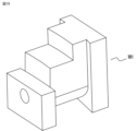
- FIG. 16 is a perspective view showing the shape of a lead holder WH according to the fifth embodiment.
- FIG. 17 shows the motor 100 in a fully assembled state, with the bracket 560 being shown in a see-through view to facilitate understanding of the internal structure.
- 18 is an enlarged cross-sectional view of a main portion of the motor 100.
- the lead wires WL are not shown.
- the lead holder WH has a function of holding the lead wire WL, has a hole with the same diameter as the lead wire WL, and is shaped to be fitted and positioned in the lead holder fitting groove WHM of the stator 520.
- the surface of the bracket 560 corresponding to the drain groove 63 is shaped so that the lead holder WH does not block the drain groove 63 when the bracket 560 is attached to the stator 520.
- the size relationship between the lead holder WH and the lead holder fitting groove WHM of the stator 520 can be set to a clearance fit dimensional relationship when ease of assembly is important, and the fitting gap can be set so that water that has flowed down the drain groove 63 of the bracket 60 is discharged to the outside of the motor 100.
- the lead holder WH is made of a highly adhesive elastic material and the dimensions of the lead holder WH and the lead holder fitting groove WHM of the stator 520 are tightly fitted together, so that water that runs down the drain groove 63 of the bracket 60 passes through the lead holder WH and is discharged from the drain outlet EX.
- FIG. 19 is a cross-sectional view of the motor 100 in the vicinity of the drain outlet EX.
- the drain groove 63 is directly connected to the drain outlet EX, but the drain outlet EX does not communicate with the inside of the motor 100 and is structured to withstand the intrusion of water due to splashes from below.
- the outlet for the lead wires WL and the drain outlet EX are separate, water from the drain groove 63 does not flow through the lead wires WL, and water is less likely to enter the interior of the motor 100.
- the drainage outlet is connected only to the drain groove, For example, in cases where the screw holes for fastening the bracket to the resin frame do not communicate with the inside of the rotating electrical machine, a drainage channel is not required, and the drainage structure can be simplified.
- a lead holder for holding a lead wire connected to a substrate of the rotating electric machine
- the frame includes a lead holder fitting groove for positioning the lead holder;
- the lead holder is shaped so as not to block the drainage groove.
- the reed holder does not impede the drainage of water flowing through the drain groove.
- FIG. 20 is a perspective view of a stator 620 according to the sixth embodiment.
- Fig. 21 is a perspective view of motor 100 according to embodiment 6, and is a see-through view of bracket 660, similar to Fig. 17.
- Drain outlet EX has a labyrinth structure in which labyrinth inner wall 65IN is provided on the inside of drain outlet EX that opens toward bracket 60 in the axial direction, and labyrinth outer wall 65OUT is provided on the outside, and labyrinth inner wall 65IN and labyrinth outer wall 65OUT are positioned so as to overlap each other when viewed from radial direction X, thereby preventing direct intrusion of water from below.
- the drain outlet has a labyrinth structure, so that reverse infiltration of water through the drain outlet can be prevented.
- Embodiment 7 The rotating electric machine according to the seventh embodiment will be described below, focusing on the differences from the first embodiment.
- 24 is an enlarged view of a main part of a motor according to embodiment 7.
- the cross-sectional view corresponds to FIG.
- FIG. 25 is an enlarged view of a main portion of FIG. 26 is an enlarged view of a main part of a motor according to embodiment 7.
- FIG. The bracket 760 of the seventh embodiment has a screw hole 60H for fixing the bracket 760 to the resin frame 24 with a screw S.
- a cylindrical seat 60H3D that communicates with the screw hole 60H and protrudes to the + axial direction Z side is provided at the edge of the inlet of the screw hole 60H.
- An outer diameter 60H3DL (outer diameter of the outermost periphery) of the seat 60H3D (third seat) is smaller than the outer diameter S1L of the head S1 of the screw S.
- a drain groove 60SM1 having the same function as the drain groove 63 described above is formed between the back surface S1R of the head S1 of the screw S that abuts against the base 60H3D of the bracket 760, the outer peripheral surface 60H3DOUT of the base 60H3D, and the end surface 60S2 on the axial Z+ side of the bracket 760.
- the drainage groove 60SM1 is formed around the fastening portion of each screw S, so that water droplets adhering to the periphery of the drainage groove 60SM1 can be easily drained vertically downward, preventing water from entering the interior of the rotating electric machine through the screw hole 60H.
- FIG. 24 and 25 show a structure in which the end face 60S2 on the axial Z+ side of the bracket 760 is flat, but as shown in FIG. 26, a drainage groove 60SM2 recessed in the axial Z- side in an annular shape parallel to the edge of the screw hole 60H on the end face 60S2 on the axial Z+ side of the bracket 760 may be formed, and the inner part of this drainage groove SM2 may be provided with a pedestal 60H4D of the same shape as the pedestal 60H3D described using FIG. 24.
- a similar effect can be obtained if the outer diameter 60H4DL of the outer circumferential surface 60H4DOUT of the cylindrical pedestal 60H4D is smaller than the outer diameter S1L of the head S1 of the screw S.
- FIG. 27 is a perspective view showing still another example of the base.
- the base 60H3D is not limited to a cylindrical shape, and can also be a cylindrical base with a portion cut out as shown in FIG. 27, or a polygonal shape such as an octagon, and as long as the outer diameter of the outermost portion of the base 60H3D is smaller than the outer diameter of the head S1 of the screw S, a similar drainage groove can be formed, thereby achieving the same effect.
- the inner diameter of the screw hole 60H is the same including the base 60H3D. This makes it easier to ensure the required area of the seat of the screw S, and prevents the screw from loosening due to the seat collapsing.
- the base and the head of the screw are fixed in contact with each other, Since the outer diameter of the outermost periphery of the base is smaller than the outer diameter of the head of the screw, a drain groove recessed in the Z- axial direction is formed on the edge of the screw hole on the end face on the Z+ axial direction of the bracket, and water droplets adhering to the head of the screw can be guided into the drain groove and downward in the vertical direction.
- the base of the bracket is cylindrical, water running around the base can be smoothly guided vertically downward.
- a radial gap motor with an inner rotor configuration has been described as an example, but in the case of an axial gap motor, a fitting portion can be provided between the stator and bracket to form a drain groove, and the same effects as in each of the embodiments can be obtained.
- the rotating part is on the outside, so it is outside the scope of this disclosure.
- the bracket 60 and the resin frame 24 may be provided with a drainage groove 63 and a drainage groove 424M1, respectively, or, as shown in FIG. 23, multiple drainage grooves 63A and 63B may be provided only on the bracket 60, which provides the same drainage function as each embodiment.
- a rotating electric machine including a stator and a rotor that rotates with an outer circumferential surface facing an inner circumferential surface of the stator,
- the stator includes a cylindrical frame and a bracket that closes an opening at an axial end of the frame, a drain groove recessed radially inward and extending circumferentially in at least one of the frame and the bracket at a fitting portion between the frame and the bracket;
- (Appendix 2) 2.
- Appendix 3 3.
- the drainage port of the stator is formed in the opening of the frame of the stator by a groove recessed toward the stator and the bracket.
- (Appendix 4) 4.
- the bracket has an annular recess on an end surface facing the stator, An end portion of the frame on the opening side is fitted into the recess, 4.
- the drain groove is formed on an inner circumferential surface of the recess.
- the bracket has an annular recess on an end surface facing the stator, an end portion of the frame on the opening side is fitted into the recess;
- the rotating electric machine according to any one of claims 1 to 3, wherein the drain groove is formed on an outer peripheral surface of an end portion of the frame on the opening side.
- (Appendix 7) 4. The rotating electric machine according to claim 2, wherein a lead wire connected to a substrate of the rotating electric machine is led out from the drain outlet.
- the drain outlet is connected only to the drain groove.
- Appendix 9 A rotating electric machine according to any one of Appendix 1 to Appendix 8, wherein when the axial width of the drain groove is W (mm) and the radial height of the drain groove is H (mm), if the material of the component in which the drain groove is provided is metal, H ⁇ W ⁇ 2.09 is satisfied, and if the material is resin, H ⁇ W ⁇ 0.21 is satisfied.
- Appendix 10 a lead holder for holding a lead wire connected to a substrate of the rotating electric machine; the frame includes a lead holder fitting groove for positioning the lead holder; 7. The rotating electric machine according to claim 1, wherein the lead holder has a shape that does not block the drain groove. (Appendix 11) 3.
- Appendix 13 A rotating electric machine as described in Appendix 2 or Appendix 3, wherein the end face of the bracket on the opening side is provided with a drainage channel that extends downward and radially inward from a starting point below and radially inward of the screw holes that fix the bracket and are located vertically above in the installation posture of the rotating electric machine, and is formed as a recess, and leads to the drain outlet.
- the drainage channel has a groove depth that gradually increases from the top to the bottom in a vertical direction in an installation posture of the rotating electric machine.
Landscapes
- Engineering & Computer Science (AREA)
- Power Engineering (AREA)
- Motor Or Generator Frames (AREA)
Abstract
回転電機(100)は、ステータ(20)と、ステータ(20)の内周面に外周面を対向させて回転するロータ(10)とを備え、ステータ(20)は、円筒状のフレーム(24)と、フレーム(24)の軸方向(Z)の端部の開口部(24Q)を閉塞するブラケット(60)とを備え、フレーム(24)とブラケット(60)との嵌合部の、フレーム(24)およびブラケット(60)の少なくとも一方に、径方向(X)の内側に凹み、周方向(Y)に延びる水切り溝(63)を有する。
Description
本開示は、回転電機に関するものである。
モータ等の回転電機を完全に防水する構造として、特許文献1のように部品の合わせ面にゴム材のガスケットを配置する構造例が開示されている。また、モータの内部への水の浸入を防止し、万一侵入した水を排水する構造として、特許文献2のように設置状態の鉛直下側に開口した水抜孔を設置する構造が開示されている。
特許文献1に使用されるゴム材のガスケットは、寸法管理が難しく、つぶして使用するためにつぶし荷重がばらつくなどの課題があり、ガスケットと接する相手部品の寸法精度、剛性、強度を確保する必要がある。
また、モータにかかる水圧が低い環境ではゴム材のシールが不要な場合があり、特許文献2のような構造にできるが、エンドハウジングとヨークハウジングを嵌めこんだ構造では、部品の寸法ばらつきなどによりエンドハウジングとヨークハウジングを安定して隙間なく密着させることが難しい。インバータ制御で駆動させるモータにおいては充電部にサージ電圧などがかかるため、充電部には、なるべく水分を近づけないようにする必要がある。水の侵入経路から充電部を遠ざければ一定の解決を図れるが、モータのサイズが大きくなってしまい、モータを搭載する機器に収まらなくなるという課題があった。
本開示は、上記のような課題を解決するための技術を開示するものであり、防水性能を確保しつつコンパクトな構造の回転電機を提供することを目的とする。
本開示に開示される回転電機は、
ステータと、前記ステータの内周面に外周面を対向させて回転するロータとを備える回転電機であって、
前記ステータは、円筒状のフレームと、前記フレームの軸方向の端部の開口部を閉塞するブラケットとを備え、
前記フレームと前記ブラケットとの嵌合部の、前記フレームおよび前記ブラケットの少なくとも一方に、径方向の内側に凹み、周方向に延びる水切り溝を有するものである。
ステータと、前記ステータの内周面に外周面を対向させて回転するロータとを備える回転電機であって、
前記ステータは、円筒状のフレームと、前記フレームの軸方向の端部の開口部を閉塞するブラケットとを備え、
前記フレームと前記ブラケットとの嵌合部の、前記フレームおよび前記ブラケットの少なくとも一方に、径方向の内側に凹み、周方向に延びる水切り溝を有するものである。
本開示に開示される回転電機によれば、防水性能を確保しつつコンパクトな構造の回転電機を提供できる。
実施の形態1.
以下、実施の形態1に係る回転電機を、図を用いて説明する。
図1は、実施の形態1に係るモータ100の断面図である。
図1に示すように、本実施の形態1では、回転電機であるモータ100は、水平横向きに設置されることとするがシャフト11の先端が鉛直上向き~水平横向きの間である限り、後述の水の侵入経路が設置状態におけるモータ100の上側、排水経路が設置状態におけるモータ100の下側となる位置関係は維持されるので、以下で説明する防水効果は成立する。また、本明細書においては、モータ100の軸方向を軸方向Zとし、シャフト11に負荷が接続される負荷側(図1の右側)を軸方向Z-とし、その反対側(図1の左側)の反負荷側を軸方向Z+とする。また、モータ100の径方向を径方向Xとし、モータ100の周方向を周方向Yとする。なお、特許請求の範囲で使用する「嵌合部」は、ステータのフレームと、後述のブラケットとが、嵌め合わされる範囲全体を指すものとする。
以下、実施の形態1に係る回転電機を、図を用いて説明する。
図1は、実施の形態1に係るモータ100の断面図である。
図1に示すように、本実施の形態1では、回転電機であるモータ100は、水平横向きに設置されることとするがシャフト11の先端が鉛直上向き~水平横向きの間である限り、後述の水の侵入経路が設置状態におけるモータ100の上側、排水経路が設置状態におけるモータ100の下側となる位置関係は維持されるので、以下で説明する防水効果は成立する。また、本明細書においては、モータ100の軸方向を軸方向Zとし、シャフト11に負荷が接続される負荷側(図1の右側)を軸方向Z-とし、その反対側(図1の左側)の反負荷側を軸方向Z+とする。また、モータ100の径方向を径方向Xとし、モータ100の周方向を周方向Yとする。なお、特許請求の範囲で使用する「嵌合部」は、ステータのフレームと、後述のブラケットとが、嵌め合わされる範囲全体を指すものとする。
モータ100は、ステータ20と、ステータ20の内周面に外周面を対向させて回転するロータ10と、ロータ10を支持するシャフト11と、シャフト11の負荷側を支持する軸受Brと、反負荷側の軸受Brを支持する反負荷側ハウジング30と、反負荷側ハウジング30の軸方向Z+側に配置され、ステータ20のコイル21に流す電流を制御する基板40と、基板40の軸方向Zの外側に放熱シート50を介して配置されるブラケット60と、基板40に電源を供給するリード線WLとを有する。放熱シート50は、基板40に生じる熱を外部に放熱するために配置している。また、ブラケット60は、ステータ20の樹脂フレーム24の反負荷側の端部の開口部24Qを閉塞する蓋である。
ステータ20は、ステータコア22に絶縁体であるインシュレータ23を介してコイル21が巻き付けられており、モールド樹脂によって外周をモールドされ、樹脂フレーム24が形成されている。樹脂フレーム24のうち、樹脂フレーム24の負荷側の端に軸受を保持する部分が負荷側ハウジング24Lである。樹脂フレーム24の反負荷側の端部が、ブラケット60の外周面と嵌め合わされる第1嵌合部24K1である。また、第1嵌合部24K1よりも負荷側に、反負荷側ハウジング30の外周面と嵌め合わせる、第1嵌合部24K1よりも内径の小さい第2嵌合部24K2を有する。
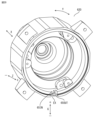
図2は、ブラケット60を軸方向Z-側から見た平面図である。
図3は、図2のA-A断面図である。
図4は、ブラケット60の斜視図である。
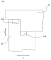
ブラケット60は、円盤状の形状をしており、樹脂フレーム24の第1嵌合部24K1と嵌め合わされる、径方向Xの外側にフランジ状に突出する外側嵌め合い部61OUTを外周面に有する。また、外側嵌め合い部61OUTよりも軸方向Z-側に、外側嵌め合い部61OUTよりも小径の径方向Xの外側に突出する内側嵌め合い部61INを外周面に有する。そして、外側嵌め合い部61OUTと内側嵌め合い部61INとの間に、ブラケット60の周方向Yの全周に渡って延び、内側嵌め合い部61INよりも小径の水切り溝63が、径方向Xの内側に凹むように形成されている。
図3は、図2のA-A断面図である。
図4は、ブラケット60の斜視図である。
ブラケット60は、円盤状の形状をしており、樹脂フレーム24の第1嵌合部24K1と嵌め合わされる、径方向Xの外側にフランジ状に突出する外側嵌め合い部61OUTを外周面に有する。また、外側嵌め合い部61OUTよりも軸方向Z-側に、外側嵌め合い部61OUTよりも小径の径方向Xの外側に突出する内側嵌め合い部61INを外周面に有する。そして、外側嵌め合い部61OUTと内側嵌め合い部61INとの間に、ブラケット60の周方向Yの全周に渡って延び、内側嵌め合い部61INよりも小径の水切り溝63が、径方向Xの内側に凹むように形成されている。
また、ブラケット60は、基板40の放熱のために放熱シート50を介して接触させる平面状の基板接触部41を備えている。ブラケット60の材質がアルミ合金、鋼鉄などの金属の場合、水切り溝63は、旋削加工で容易に形成できる。ブラケット60の材質が樹脂の場合は、スライド式の金型で成形するか、成形後の旋削加工によって形成できる。
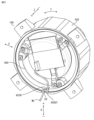
水切り溝63の最小径部分よりも径方向の内側に、ブラケット60をねじで固定するためのねじ孔60Hが3つ、軸方向Zに開いている。そして、ブラケット60の軸方向Z-側の端面60Sには、排水路64を備える。排水路64は、ねじ孔60Hのうち、モータ100の設置姿勢における鉛直方向Gの最も上方G+側(図2の上側)にあるねじ孔60Hの下方、かつ径方向Xの内側の起点64Sから、鉛直方向Gの下方G-側かつ、起点64Sよりも径方向Xの内側に延びるように、軸方向Z+側に凹んで形成されている。すなわち、この排水路64は、最も鉛直方向Gの上方G+側にあるねじ孔60Hと基板接触部41の間から始まり、基板接触部41の下端よりも更に下方まで延伸し、ブラケット60の軸方向Z-側の端面60S(内側面)に設けられ軸方向Z+側(外側)に凹んだ、起点64Sよりも径方向Xの内側に形成された集水部64Pに繋がっている。
排水路64は、水が、ねじ孔60Hから、モータ100の内側に浸入した際に、集水部64Pを介して、侵入した水を後述する鉛直方向Gの下方G-側に設けたの排水口まで案内する役割を担う。排水路64は、ブラケット60のねじ孔60Hが、内側嵌め合い部61INよりも径方向の内側にある場合にのみ有効であり、ブラケット60のねじ孔60Hが内側嵌め合い部61INよりも径方向Xの外側に配置されている場合は不要である。なお、排水路64は、起点64Sから下方G-に向かって、溝の深さが、軸方向Z+側に次第に深くなるように形成されている傾斜溝64K1と、傾斜溝64K1の下端部64KUに繋がり同じ深さで集水部64Pに繋がる案内溝64K2とからなる。
すなわち、排水路64において、ブラケット60のねじ孔60Hに最も近い起点64Sの部分の底面が、最も軸方向Z-側に位置し、ブラケット60のねじ孔60Hから遠ざかるにつれて、排水路64を構成する傾斜溝64K1の底面が軸方向Z+側に傾斜して、傾斜溝64K1の軸方向Zの深さが深くなる。そして、排水路64の傾斜溝64K1の下端部64KUは、軸方向Zに底面が傾斜しない全長に渡って同じ深さの排水路64の案内溝64K2の上端部に接続されている。これによって、ねじ孔60Hから侵入し、下方に流れる水を、コアンダ効果によって集水できる。
すなわち、排水路64において、ブラケット60のねじ孔60Hに最も近い起点64Sの部分の底面が、最も軸方向Z-側に位置し、ブラケット60のねじ孔60Hから遠ざかるにつれて、排水路64を構成する傾斜溝64K1の底面が軸方向Z+側に傾斜して、傾斜溝64K1の軸方向Zの深さが深くなる。そして、排水路64の傾斜溝64K1の下端部64KUは、軸方向Zに底面が傾斜しない全長に渡って同じ深さの排水路64の案内溝64K2の上端部に接続されている。これによって、ねじ孔60Hから侵入し、下方に流れる水を、コアンダ効果によって集水できる。
図5は、ステータ20の斜視図である。
図6は、ステータ20の断面図である。
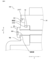
図7は、モータ100の要部拡大図である。ブラケット60と、樹脂フレーム24との嵌合部分の拡大図である。
ステータ20の樹脂フレーム24の軸方向Z+側の端部に、ブラケット60の外側嵌め合い部61OUTと同径の外側嵌め合い部24OUTが形成され、外側嵌め合い部24OUTの軸方向Z-側に、ブラケット60の内側嵌め合い部61INと同径の内側嵌め合い部24INが形成され、ステータ20にブラケット60が組みつけられた際にそれぞれが嵌め合わされる。すなわち、樹脂フレーム24の反負荷側の端部には、軸方向Z-側に向かって円環状に凹んだザグリ部24Zが形成されており、ザグリ部24Zの径方向Xの外側壁面が外側嵌め合い部24OUTであり、ザグリ部24Zよりも軸方向Z-側の壁面が内側嵌め合い部24INである。
図6は、ステータ20の断面図である。
図7は、モータ100の要部拡大図である。ブラケット60と、樹脂フレーム24との嵌合部分の拡大図である。
ステータ20の樹脂フレーム24の軸方向Z+側の端部に、ブラケット60の外側嵌め合い部61OUTと同径の外側嵌め合い部24OUTが形成され、外側嵌め合い部24OUTの軸方向Z-側に、ブラケット60の内側嵌め合い部61INと同径の内側嵌め合い部24INが形成され、ステータ20にブラケット60が組みつけられた際にそれぞれが嵌め合わされる。すなわち、樹脂フレーム24の反負荷側の端部には、軸方向Z-側に向かって円環状に凹んだザグリ部24Zが形成されており、ザグリ部24Zの径方向Xの外側壁面が外側嵌め合い部24OUTであり、ザグリ部24Zよりも軸方向Z-側の壁面が内側嵌め合い部24INである。
図5に示すように、ザグリ部24Zの鉛直方向Gの下方G-側の端部には、ブラケット60と組み合わせることによって、図1に示す排水口EX兼リード線WL用の引き出し口となる溝27を有する。溝27は、樹脂フレーム24の軸方向Z+の端部に軸方向Z-方向に凹んで形成され、溝27の軸方向Zの範囲は、軸方向Z+側の端部から、ザグリ部24Zの底面よりも軸方向Z-側までになる。排水口EX兼リード線WL用の引き出し口は、リード線WLの太さ、本数に応じて、鉛直下側部分に配置する限り複数個を設けてもよく、排水口EXとリード線WL用の引き出し口を別々に設けてもよい。ただし、モータ100の使用環境によっては、水しぶきなどが下から入る可能性もあるため、排水口EX兼リード線WL用の引き出し口の数は少ないほうが望ましい。
ごく少量の水しか侵入しないため、排水口EXは通気できる程度に開口していればよく、リード線WLの固定のための部品を排水口EX兼リード線WL用の引き出し口にはめ込んでもよいし、下からの水しぶきなどへの対策のためにリード線WLを吐き出せる範囲で後述するラビリンス構造にしてもよい。ここで、図6に示すように、排水口EX兼リード線WL用の引き出し口の内側の排水開口部27INは、図1に示すようにブラケット60の水切り溝63に連通している。すなわち、排水口EXは、樹脂フレーム24においてブラケット60よりも軸方向Z-側の内部、すなわち樹脂フレーム24とブラケット60との第1嵌合部24K1側と軸方向反対側の内部に連通している。
内側嵌め合い部24INの径方向内側には、ブラケット60のねじ孔60Hに対応する位置に、ブラケット固定用ねじ穴24H1と、反負荷側ハウジング固定用ねじ穴24H2とが設けられている。ブラケット固定用ねじ穴24H1は、モータ100をよりコンパクトにするために内側嵌め合い部24INよりも径方向Xの内側に配置したが、モータ100のサイズが許されるならばブラケット固定用ねじ穴24H1は、内側嵌め合い部24INよりも径方向Xの外側に配置しても良い。ブラケット固定用ねじ穴24H1が内側嵌め合い部24INよりも径方向Xの外側にある場合は、前述のブラケット60の排水路64は設けなくてもよい。
ブラケット60及びステータ20に設けられた外側嵌め合い部61OUT、24OUTと、内側嵌め合い部61IN、24INは、製造上のばらつきによって、同軸度および真円度などの幾何精度、或いは内径、外径などの寸法精度にばらつきが生じ、双方の嵌め合い部を締まり嵌めにすると無理が生じ、ブラケット60のステータ20への組み付けが難しくなる。そのため、外側嵌め合い部61OUT、24OUT、内側嵌め合い部61IN、24INのいずれか一組みまたは両組みが、それぞれの間に隙間を残すような隙間嵌め寸法とする。
反負荷側ハウジング30とブラケット60の取り付け位置の関係から、上述のブラケット固定用ねじ穴24H1の台座24H1Dと、反負荷側ハウジング固定用ねじ穴24H2の台座24H2Dの位置は、ブラケット固定用ねじ穴24H1の台座24H1Dの方が、他方よりも軸方向Z+側に突出している。そこで、モータ100の設置姿勢における軸方向Z+側にあるブラケット固定用ねじ穴24H1の台座24H1Dには、ザグリ部24Zの外周面に沿って、軸方向Z-方向に凹んだ台座溝DMを設けている。台座溝DMは、後述する水の滞留対策に効果がある。
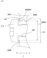
図8は、モータ100の要部拡大図である。
図9は、モータ100の断面模式図である。
図10は、モータ100の要部断面斜視図である。
図9において、基板40とブラケット60は、全体像を描いている。
図8、図9の矢印は、ブラケット60とステータ20の樹脂フレーム24との嵌合部から進入した水の流れる経路を示している。
図9は、モータ100の断面模式図である。
図10は、モータ100の要部断面斜視図である。
図9において、基板40とブラケット60は、全体像を描いている。
図8、図9の矢印は、ブラケット60とステータ20の樹脂フレーム24との嵌合部から進入した水の流れる経路を示している。
前述のように、ブラケット60の外側嵌め合い部61OUTと、樹脂フレーム24の外側嵌め合い部24OUTの間には、微小な隙間があるために、少量の水が、ブラケット60の外側嵌め合い部61OUTとステータ20の外側嵌め合い部24OUTの間の隙間から、モータ100の内部に向かって侵入する。ここから侵入した水は、鉛直方向Gの下方G-側に流れ、水切り溝63にトラップされ、水切り溝63の中で図8の奥行方向と手前方向に分岐し、図9に示すように径方向Xに凹んだ水切り溝63を伝って下方G-に流れ、水切り溝63と繋がっている、上述の溝27とブラケット60とによって形成される排水口EX(兼リード線WL用の引き出し口)を通ってモータ100の外部へ排出される。
水が内側嵌め合い部61IN、24INよりも、モータ100の内側、すなわち、軸方向Z-側に入らないようにするためには、水切り溝63に十分な排水能力が必要である。
そこで、図8に示す水切り溝63の軸方向Zの幅Wと、水切り溝63の径方向Xの深さHを設定以下に示すように設定する。排水能力が足りていても、水切り溝63の断面が小さ過ぎる場合、毛細管現象によって内側嵌め合い部61IN、24INの間にまで水が浸透する場合がある。
そこで、図8に示す水切り溝63の軸方向Zの幅Wと、水切り溝63の径方向Xの深さHを設定以下に示すように設定する。排水能力が足りていても、水切り溝63の断面が小さ過ぎる場合、毛細管現象によって内側嵌め合い部61IN、24INの間にまで水が浸透する場合がある。
ここで、毛細管現象による水位上昇量h=2Tcosθ/ρgr(T:表面張力、θ:接触角、ρ:密度、g:重力加速度、r:管の半径)と表されるので、rをW、hをHと置き換えた不等式が、HとWを決める目安となる。ρ=1000kg/m3、g=9.8m/s2とし、水の表面張力は温度によりT=0.0589~0.0756N/mの範囲、水の接触角は表面粗さにもよるがθ=20°(ガラス)、70~89°(樹脂)、40~80°(金属)の範囲とすると、水切り溝63深さH(mm)と水切り溝63幅W(mm)の関係は、次式で表される。
H・W≧11.3~14.5 (ガラス)
H・W≧0.21~5.28 (樹脂)
H・W≧2.09~11.8 (金属)
H・W≧11.3~14.5 (ガラス)
H・W≧0.21~5.28 (樹脂)
H・W≧2.09~11.8 (金属)
図10は、ブラケット60をステータ20に固定するねじ用のねじ孔60Hからモータ100の内部へ侵入した水の流れる経路を示す図である。
図10において、侵入した水の流れる経路がわかるように、ステータ20のねじ孔60Hの部分で切断した断面と、ブラケット60、基板40を示している。簡単のためにロータ、ステータ20内部のステータコア22、インシュレータ23、コイル21は表示していない。3か所のねじSのうち、ステータ20の断面が残る部分のねじSだけを表示している。
図10において、侵入した水の流れる経路がわかるように、ステータ20のねじ孔60Hの部分で切断した断面と、ブラケット60、基板40を示している。簡単のためにロータ、ステータ20内部のステータコア22、インシュレータ23、コイル21は表示していない。3か所のねじSのうち、ステータ20の断面が残る部分のねじSだけを表示している。
ねじSの近傍は、ねじSの軸力によって、ブラケット60と樹脂フレーム24とが密着されており、水の侵入はほとんどないが、万一、少量の水が浸入した場合、図10に示す矢印の経路を辿って、水はモータ100の外に排出される。最も高い位置にあるねじS用のねじ孔60Hから侵入した水は、ブラケット60に設けられた排水路64を伝い、集水部64Pを通って排水口EXから外部に排水される。
このように、水が、基板40に近づかないように排水口EXまで案内する。また、排水路64を辿らなかった水は、鉛直方向Gの下側G-側のブラケット固定用ねじ穴24H1の台座24H1Dの部分に溜まらないように、前述した図5に示す台座溝DMを伝って排水口EXまで案内される。
このように、ブラケット60とステータ20が嵌め合う面に水切り溝63を設け、モータ100の鉛直方向Gの下方G-側に排水口EXを設けることで、ステータ20の樹脂フレーム24とブラケット60との嵌合部から侵入した微量の水を、基板40に触れずにモータ100の外部に排水できる構造を実現できる。
また、モータ100のコンパクト化のためにブラケット60の固定用のねじSを、内側嵌め合い部61IN、24INよりも径方向Xの内側に配置する場合に、ねじ孔60Hと基板接触部41の間から鉛直方向Gの下方G-側、かつ径方向Xの外側に延びる溝状の排水路64をブラケット60に設けることによって、基板40の水濡れを防止することができる。
図28は、ブラケット60の他の固定方法を示す図であり、固定前を示す図である。
図29は、ブラケット60の他の固定方法を示す図であり、固定後を示す図である。
これまで、ブラケット60を固定する手段として分解性に有利なねじ止め構造を例に説明したが、図28に示すように、ステータのフレームから軸方向Z+側に突出する突出部24Pをブラケット60の孔60H2に挿入した後に、図29に示すように、熱または機械的手段を有するかしめツールTLによって突出部24Pをかしめて頭部24Tを形成してブラケット60を固定する構造としてもよい。例えば突出部24Pが樹脂製の場合は、熱溶着、超音波溶着で頭部24Tを形成でき、金属製の場合はリベットかしめなどを採用できる。
図28は、ブラケット60の他の固定方法を示す図であり、固定前を示す図である。
図29は、ブラケット60の他の固定方法を示す図であり、固定後を示す図である。
これまで、ブラケット60を固定する手段として分解性に有利なねじ止め構造を例に説明したが、図28に示すように、ステータのフレームから軸方向Z+側に突出する突出部24Pをブラケット60の孔60H2に挿入した後に、図29に示すように、熱または機械的手段を有するかしめツールTLによって突出部24Pをかしめて頭部24Tを形成してブラケット60を固定する構造としてもよい。例えば突出部24Pが樹脂製の場合は、熱溶着、超音波溶着で頭部24Tを形成でき、金属製の場合はリベットかしめなどを採用できる。
なお、実施の形態1では、基板40の水濡れの防止を例に説明したが、基板40が内蔵されていないモータであっても、電源端子の水濡れを防止する目的でも本実施の形態1の構造を採用し、水切り溝63および排水路64を設けることができる。この場合、排水路64の起点64Sは、最も高い位置にあるねじ穴Sと端子の間とする。
また、これまでステータ20の構造として樹脂フレーム24で覆った構造例を示したが、円筒形状またはおわん型形状のフレームにステータ20コアを圧入または焼嵌めした構造とし、フレームの軸方向Zの端面に本実施の形態と同様の外側嵌め合い部24OUT、内側嵌め合い部24INを設けることで同様の効果を得られることは言うまでも無い。
図11は、モータ100の他の例を示す断面図である。
モータ100は、反負荷側ハウジング30が、ブラケット60と一体化した図11のような構成であっても良い。図11では、ブラケット60の水切り溝63は、周方向Yに対して垂直な断面が四角形状として示しているが、断面形状はこの限りではなく、径方向Xの外側に開口した形状であれば、断面三角形状、或いは断面半円形状の断面としても本実施の形態の効果を奏する。
モータ100は、反負荷側ハウジング30が、ブラケット60と一体化した図11のような構成であっても良い。図11では、ブラケット60の水切り溝63は、周方向Yに対して垂直な断面が四角形状として示しているが、断面形状はこの限りではなく、径方向Xの外側に開口した形状であれば、断面三角形状、或いは断面半円形状の断面としても本実施の形態の効果を奏する。
実施の形態1に係る回転電機によれば、
ステータと、前記ステータの内周面に外周面を対向させて回転するロータとを備える回転電機であって、
前記ステータは、円筒状のフレームと、前記フレームの軸方向の端部の開口部を閉塞するブラケットとを備え、
前記フレームと前記ブラケットとの嵌合部の、前記フレームおよび前記ブラケットの少なくとも一方に、径方向の内側に凹み、周方向に延びる水切り溝を有するので、
防水性能を確保しつつコンパクトな構造の回転電機を提供できる。
ステータと、前記ステータの内周面に外周面を対向させて回転するロータとを備える回転電機であって、
前記ステータは、円筒状のフレームと、前記フレームの軸方向の端部の開口部を閉塞するブラケットとを備え、
前記フレームと前記ブラケットとの嵌合部の、前記フレームおよび前記ブラケットの少なくとも一方に、径方向の内側に凹み、周方向に延びる水切り溝を有するので、
防水性能を確保しつつコンパクトな構造の回転電機を提供できる。
また、前記回転電機の設置姿勢において、鉛直下方に、内部に侵入した水を外部に排出する排水口を有し、前記水切り溝は、当該排水口に連通するので、
嵌合部から侵入した水は、嵌合部の外周面を伝って排水口に案内されるので、回転電機の内部への浸水を防止できる。
また、前記排水口は、前記フレームにおいて、前記ブラケットよりも前記嵌合部側とは軸方向反対側の内部に連通するので、ねじ孔を伝ってブラケットの内部に侵入する水を排水できる。
嵌合部から侵入した水は、嵌合部の外周面を伝って排水口に案内されるので、回転電機の内部への浸水を防止できる。
また、前記排水口は、前記フレームにおいて、前記ブラケットよりも前記嵌合部側とは軸方向反対側の内部に連通するので、ねじ孔を伝ってブラケットの内部に侵入する水を排水できる。
また、前記ステータの排水口は、前記ステータの前記フレームの前記開口部に形成され、前記ステータ側に凹む溝と、前記ブラケットとによって形成されるので、簡便に排水口を形成できる。
また、前記排水口から前記回転電機の基板に接続されるリード線が導出されているので、別途リード線の導出口を設ける必要がなく、回転電機の製造コストを低減できる。
また前記水切り溝の軸方向の幅をW(mm)と、径方向の高さをH(mm)としたとき、前記水切り溝を設けた部材の材質が金属の場合は、H・W≧2.09、樹脂の場合はH・W≧0.21を満たすので、十分な排水能力を確保できる。
また、前記フレームと、前記ブラケットとの間には、他の部材が配置されていないので、回転電機の製造コストを軽減できる。
また、前記ブラケットの前記開口部側の端面には、前記嵌合部よりも径方向の内側に設けられた孔のうち、前記回転電機の設置姿勢における鉛直方向の上側にある孔の下方、かつ径方向の内側の起点から、下方かつ、径方向の内側に延び、かつ凹んで形成され、前記排水口に繋がる排水路を備えるので、ねじ孔から侵入する水が、基板等に影響することを防止できる。
また、前記排水路は、前記回転電機の設置姿勢における鉛直方向の上方から下方に向かって、起点から次第に溝の深さが深くなる傾斜溝を有するので、ねじ孔から侵入し、下方に流れる水を、コアンダ効果によって集水できる。
また、前記排水路は、前記ブラケットの内側面に設けられ、軸方向の外側に凹んだ集水部に接続され、前記集水部は、前記排水口に繋がっているので、ブラケットから回転電機の内部に侵入した水を集水部からまとめて排水口に案内できる。
また、前記排水路は、前記ブラケットの内側面に設けられ、軸方向の外側に凹んだ集水部に接続され、前記集水部は、前記排水口に繋がっているので、ブラケットから回転電機の内部に侵入した水を集水部からまとめて排水口に案内できる。
なお、本実施の形態では、ブラケット60は、反負荷側に設けたが、負荷側に樹脂フレーム24が開口部を有するタイプであっても適用できる。
実施の形態2.
以下、実施の形態2に係る回転電機を、実施の形態1と異なる部分を中心に説明する。
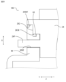
図12は、実施の形態2のブラケット260とステータ220の樹脂フレーム224との嵌合部を示す図であり、実施の形態1の図8に対応する部分の図である。
本実施の形態2では、実施の形態1においてステータ20の軸方向Z+側の端部に設けていたザグリ部24Zは無い。一方、円盤状のブラケット260の軸方向Z-側の端面260Sから軸方向Z+側に環状に凹む凹部260Mをブラケット260の周方向Yの全周に渡って設けている。この凹部260Mに、ステータ220の樹脂フレーム224の軸方向Z+側の端部が嵌め込まれている。
以下、実施の形態2に係る回転電機を、実施の形態1と異なる部分を中心に説明する。
図12は、実施の形態2のブラケット260とステータ220の樹脂フレーム224との嵌合部を示す図であり、実施の形態1の図8に対応する部分の図である。
本実施の形態2では、実施の形態1においてステータ20の軸方向Z+側の端部に設けていたザグリ部24Zは無い。一方、円盤状のブラケット260の軸方向Z-側の端面260Sから軸方向Z+側に環状に凹む凹部260Mをブラケット260の周方向Yの全周に渡って設けている。この凹部260Mに、ステータ220の樹脂フレーム224の軸方向Z+側の端部が嵌め込まれている。
すなわち、ステータ220の樹脂フレーム224の軸方向Z+側の端部の外周面が、外側嵌め合い部224OUTであり、凹部260Mの外周面が、外側嵌め合い部261OUTである。また、ステータ220の樹脂フレーム224の軸方向Z+側の端部の内周面が、内側嵌め合い部224INであり、凹部260Mの内周面が、内側嵌め合い部261INである。そして、凹部260Mの内周面に、ブラケット260の径方向Xの内側に凹んだ水切り溝263が、ブラケット260の周方向Yの全周に渡って形成されている。これ以外の構造は、実施の形態1と同様である。
図12に矢印で示すとおり、外側嵌め合い部224OUT、261OUTの間から侵入した水は、実施の形態1と同様に水切り溝63を伝って、排水口EXからモータ100の外部に排出される。本実施の形態2の場合、図12の左側からの水が侵入しにくい構造となるので、反負荷側が水に晒されるような環境下でのモータ100の利用に効果的である。
実施の形態2に係る回転電機によれば、
前記ブラケットは、前記ステータ側の端面に環状に凹む凹部を備え、
前記フレームの前記開口部側の端部が、前記凹部に嵌合され、
前記水切り溝は、前記凹部の内周面に形成されているので、
側が水に晒される場合に防水効果が高い。
前記ブラケットは、前記ステータ側の端面に環状に凹む凹部を備え、
前記フレームの前記開口部側の端部が、前記凹部に嵌合され、
前記水切り溝は、前記凹部の内周面に形成されているので、
側が水に晒される場合に防水効果が高い。
実施の形態3.
以下、実施の形態3に係る回転電機を、実施の形態1、2と異なる部分を中心に説明する。
図13は、実施の形態3に係るブラケット360とステータ320の樹脂フレーム324との嵌合部の構造を示す図であり、実施の形態1の図8に対応する部分の図である。本実施の形態では外側嵌め合い部がなく、内側嵌め合い部だけでブラケット360の外周面の一部がステータ320の内周面に嵌め合う構造となっている。ステータ320の樹脂フレーム324の軸方向Z+側の端部の内周面が、内側嵌め合い部324INであり、ブラケット360の軸方向Z-側の外周面が、軸方向Z+側の端部よりも小径に形成されている内側嵌め合い部361INである。
以下、実施の形態3に係る回転電機を、実施の形態1、2と異なる部分を中心に説明する。
図13は、実施の形態3に係るブラケット360とステータ320の樹脂フレーム324との嵌合部の構造を示す図であり、実施の形態1の図8に対応する部分の図である。本実施の形態では外側嵌め合い部がなく、内側嵌め合い部だけでブラケット360の外周面の一部がステータ320の内周面に嵌め合う構造となっている。ステータ320の樹脂フレーム324の軸方向Z+側の端部の内周面が、内側嵌め合い部324INであり、ブラケット360の軸方向Z-側の外周面が、軸方向Z+側の端部よりも小径に形成されている内側嵌め合い部361INである。
ブラケット360の内側嵌め合い部361INの軸方向Z+側には、径方向の内側に凹んだ水切り溝363が、ブラケット360の周方向Yの全周に渡って形成されている。これ以外の構造は、実施の形態1と同様である。
図13に矢印で示すとおり、ブラケット360とステータ320の樹脂フレーム324との間から侵入した水は、実施の形態1と同様に水切り溝363を伝って、排水口EXからモータ100の外部に排出される。本実施の形態3は、実施の形態1および実施の形態2に比べて、防水性能は若干下がるが、外側嵌め合い部がないために、製造上の寸法管理箇所が減り、モータ100を生産し易くなるという利点がある。
実施の形態3に係る回転電機によれば、
前記フレームの内周面と、前記ブラケットの外周面とが嵌合され、前記水切り溝は、前記ブラケットの外周面に形成されているので、
回転電機の製造コストを低減できる。
前記フレームの内周面と、前記ブラケットの外周面とが嵌合され、前記水切り溝は、前記ブラケットの外周面に形成されているので、
回転電機の製造コストを低減できる。
実施の形態4.
以下、実施の形態4に係る回転電機を、実施の形態2と異なる部分を中心に説明する。
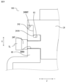
図14は、実施の形態4に係るブラケット460とステータ420樹脂フレーム424と嵌合部を示す図であり、実施の形態2の図12に対応する部分の図である。
以下、実施の形態4に係る回転電機を、実施の形態2と異なる部分を中心に説明する。
図14は、実施の形態4に係るブラケット460とステータ420樹脂フレーム424と嵌合部を示す図であり、実施の形態2の図12に対応する部分の図である。
実施の形態2と同様に、円盤状のブラケット460の軸方向Z-側の端面460Sに、軸方向Z+側に環状に凹む凹部460Mをブラケット460の周方向Yの全周に渡って設けている。この凹部460Mに、ステータ420の樹脂フレーム424の軸方向Z+側の端部が嵌め込まれている。
すなわち、ステータ420の樹脂フレーム424の軸方向Z+側の端部の外周面が、外側嵌め合い部424OUTであり、凹部460Mの径方向Xの外側の壁面が、外側嵌め合い部461OUTである。また、ステータ420の樹脂フレーム424の軸方向Z+側の端部の内周面が、内側嵌め合い部424INであり、凹部460Mの径方向Xの内側の壁面が、内側嵌め合い部461INである。そして、樹脂フレーム424の外周面である外側嵌め合い部424OUTに、ステータ420の径方向Xの内側に向かって凹んだ水切り溝424M1が、樹脂フレーム424の周方向Yの全周に渡って形成されている。これ以外の構造は、実施の形態3と同様である。
図14に矢印で示すとおり、外側嵌め合い部424OUT、461OUTの間から侵入した水は、実施の形態1と同様に水切り溝424M1を伝って、排水口EXからモータ100の外部に排出される。本実施の形態4の場合も、図14の左側からの水に対し侵入しにくい構造となるので、反負荷側が水に晒されるような環境下での利用に効果的である。
実施の形態4に係る回転電機によれば、
前記ブラケットは、前記ステータ側の端面に環状に凹む凹部を備え、
前記フレームの前記開口部側の端部が前記凹部に嵌合され、
前記水切り溝は、前記フレームの前記開口部側の端部の外周面に形成されているので、
開口部側が水に晒される場合に防水効果が高い。
前記ブラケットは、前記ステータ側の端面に環状に凹む凹部を備え、
前記フレームの前記開口部側の端部が前記凹部に嵌合され、
前記水切り溝は、前記フレームの前記開口部側の端部の外周面に形成されているので、
開口部側が水に晒される場合に防水効果が高い。
実施の形態5.
以下、実施の形態5に係る回転電機を、実施の形態1と異なる部分を中心に説明する。
図15は、ステータ520の斜視図である。樹脂フレーム524は、モータ100の設置姿勢に対する鉛直方向Gの下方G-に溝形状の排水口EXとリードホルダ嵌合溝WHMとを有する。リードホルダ嵌合溝WHM以外の形状は他の実施の形態と同様である。
以下、実施の形態5に係る回転電機を、実施の形態1と異なる部分を中心に説明する。
図15は、ステータ520の斜視図である。樹脂フレーム524は、モータ100の設置姿勢に対する鉛直方向Gの下方G-に溝形状の排水口EXとリードホルダ嵌合溝WHMとを有する。リードホルダ嵌合溝WHM以外の形状は他の実施の形態と同様である。
図16は、実施の形態5に係るリードホルダWHの形状を示す斜視図である。
図17は、モータ100の組立完了状態を示し、内部構造の理解を助けるため、ブラケット560を透過させた図である。
図18は、モータ100の要部拡大断面図である。リード線WLは描いていない。
リードホルダWHは、リード線WLを保持する機能があり、リード線WLと同径の孔を有し、ステータ520のリードホルダ嵌合溝WHMと嵌合して位置決めされる形状となっている。また、ブラケット560の水切り溝63に対応する面は、ブラケット560をステータ520に組み付けたときに、リードホルダWHが、水切り溝63を塞がない形状となっている。
図17は、モータ100の組立完了状態を示し、内部構造の理解を助けるため、ブラケット560を透過させた図である。
図18は、モータ100の要部拡大断面図である。リード線WLは描いていない。
リードホルダWHは、リード線WLを保持する機能があり、リード線WLと同径の孔を有し、ステータ520のリードホルダ嵌合溝WHMと嵌合して位置決めされる形状となっている。また、ブラケット560の水切り溝63に対応する面は、ブラケット560をステータ520に組み付けたときに、リードホルダWHが、水切り溝63を塞がない形状となっている。
リードホルダWHとステータ520のリードホルダ嵌合溝WHMの大小関係は、組立性を重視する場合は隙間嵌めの寸法関係とし、嵌合隙間からもブラケット60の水切り溝63を伝ってきた水がモータ100の外部に排出される設定にできる。
リード線WLの被水を防止したい場合は、リードホルダWHの材質を密着性の高い弾性体とし、リードホルダWHと、ステータ520のリードホルダ嵌合溝WHMの寸法関係を締まり嵌めとすることで、ブラケット60の水切り溝63を伝ってきた水は、リードホルダWHを通過し、排水口EXから排出される。
図19は、モータ100の排水口EX近傍の断面を示す図である。
水切り溝63は、排水口EXに直結されているが、排水口EXは、モータ100の内部とは通じておらず、下からの水しぶきなどによる水の侵入に耐えられる構造となっている。
また、リード線WL用の引き出し口と排水口EXを分けたため、水切り溝63からの水がリード線WLを伝わらず、モータ100の内部に水は入りにくいという効果を奏する。
水切り溝63は、排水口EXに直結されているが、排水口EXは、モータ100の内部とは通じておらず、下からの水しぶきなどによる水の侵入に耐えられる構造となっている。
また、リード線WL用の引き出し口と排水口EXを分けたため、水切り溝63からの水がリード線WLを伝わらず、モータ100の内部に水は入りにくいという効果を奏する。
実施の形態5に係る回転電機によれば、
前記排水口は、前記水切り溝のみに繋がっているので、
例えば、ブラケットと樹脂フレームとを締結するねじ穴が、回転電機の内部に連通していないような場合に排水路が不要となり、排水構造を簡単にできる。
前記排水口は、前記水切り溝のみに繋がっているので、
例えば、ブラケットと樹脂フレームとを締結するねじ穴が、回転電機の内部に連通していないような場合に排水路が不要となり、排水構造を簡単にできる。
また、前記回転電機の基板に接続されるリード線を保持するリードホルダを備え、
前記フレームは、前記リードホルダを位置決めするリードホルダ嵌合溝を備え、
前記リードホルダは、前記水切り溝を塞がない形状であるので、
リードホルダが、水切り溝を流れる水の排水を妨げることがない。
前記フレームは、前記リードホルダを位置決めするリードホルダ嵌合溝を備え、
前記リードホルダは、前記水切り溝を塞がない形状であるので、
リードホルダが、水切り溝を流れる水の排水を妨げることがない。
実施の形態6.
以下、実施の形態6に係る回転電機を、実施の形態1と異なる部分を中心に説明する。
図20は、実施の形態6に係るステータ620の斜視図である。
図21は、実施の形態6に係るモータ100の斜視図であり、図17と同様に、ブラケット660を透過した図である。排水口EXは、軸方向のブラケット60側に開いた排水口EXの内側にラビリンス内壁65IN、外側にラビリンス外壁65OUTを設けたラビリンス構造となっており、ラビリンス内壁65INとラビリンス外壁65OUTは径方向Xから見たときに互い重なり合う位置関係となっているため、下方からの水の直接的な侵入を防ぐ構成となっている。
以下、実施の形態6に係る回転電機を、実施の形態1と異なる部分を中心に説明する。
図20は、実施の形態6に係るステータ620の斜視図である。
図21は、実施の形態6に係るモータ100の斜視図であり、図17と同様に、ブラケット660を透過した図である。排水口EXは、軸方向のブラケット60側に開いた排水口EXの内側にラビリンス内壁65IN、外側にラビリンス外壁65OUTを設けたラビリンス構造となっており、ラビリンス内壁65INとラビリンス外壁65OUTは径方向Xから見たときに互い重なり合う位置関係となっているため、下方からの水の直接的な侵入を防ぐ構成となっている。
実施の形態6に係る回転電機によれば、
前記排水口は、ラビリンス構造であるので、排水口からの水の逆浸入を防止できる。
前記排水口は、ラビリンス構造であるので、排水口からの水の逆浸入を防止できる。
実施の形態7.
以下、実施の形態7に係る回転電機を、実施の形態1と異なる部分を中心に説明する。
図24は、実施の形態7に係るモータの要部拡大図である。実施の形態1の図7に相当する箇所の断面図である。
図25は、図24の要部拡大図である。
図26は、実施の形態7に係るモータの要部拡大図である。台座の他の例を示す図である。
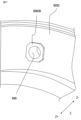
本実施の形態7のブラケット760は、ブラケット760をねじSによって樹脂フレーム24に固定するねじ孔60Hを備える。そして、ねじ孔60Hの入口の縁には、ねじ孔60Hに連通し、軸方向Z+側に突出する円筒状の台座60H3Dを備える。台座60H3D(第3台座)の外径60H3DL(最外周部の外径)は、ねじSの頭部S1の外径S1Lよりも小さい。
以下、実施の形態7に係る回転電機を、実施の形態1と異なる部分を中心に説明する。
図24は、実施の形態7に係るモータの要部拡大図である。実施の形態1の図7に相当する箇所の断面図である。
図25は、図24の要部拡大図である。
図26は、実施の形態7に係るモータの要部拡大図である。台座の他の例を示す図である。
本実施の形態7のブラケット760は、ブラケット760をねじSによって樹脂フレーム24に固定するねじ孔60Hを備える。そして、ねじ孔60Hの入口の縁には、ねじ孔60Hに連通し、軸方向Z+側に突出する円筒状の台座60H3Dを備える。台座60H3D(第3台座)の外径60H3DL(最外周部の外径)は、ねじSの頭部S1の外径S1Lよりも小さい。
ブラケット760の台座60H3Dと当接するねじSの頭部S1の裏面S1Rと、台座60H3Dの外周面60H3DOUTと、ブラケット760の軸方向Z+側の端面60S2との間に、上述の水切り溝63と同様の機能を有する水切り溝60SM1が形成されている。
このように、各ねじSの締結部の周囲に水切り溝60SM1が形成されるために、水切り溝60SM1の周囲に付着する水滴が鉛直下方向に排出され易く、ねじ孔60Hから回転電機の内部へ水が浸入することを防止できる。
図24、図25では、ブラケット760の軸方向Z+側の端面60S2が平面となっている構造を示したが、図26に示すように、ブラケット760の軸方向Z+側の端面60S2のねじ孔60Hの縁に平行に円環状に軸方向Z-側に凹む水切り溝60SM2を形成し、この水切り溝SM2の内側部分に、図24を用いて説明した台座60H3Dと同型状の台座60H4Dを設けてもよい。円筒状の台座60H4Dの外周面60H4DOUTの外径60H4DLが、ねじSの頭部S1の外径S1Lよりも小さければ同様の効果を得られる。
図27は、台座のさらに他の例を示す斜視図である。
また、ねじSの座面の必要面積を確保できる範囲で、台座60H3Dは円筒形状に限らず、図27に示すような、円筒形状の台座の一部切り欠いた形状、或いは八角形などの多角形形状としても、台座60H3Dの最外周部の外径が、ねじSの頭部S1の外径よりも小径のであれば、同様の水切り溝を形成できるので同様の効果を発揮できる。
なお、ねじ孔60Hの内径は、台座60H3Dを含めて同じである。このため、ねじSの座面の必要面積を確保し易くなり、座面の陥没等によるねじの緩みを防止できる。
また、ねじSの座面の必要面積を確保できる範囲で、台座60H3Dは円筒形状に限らず、図27に示すような、円筒形状の台座の一部切り欠いた形状、或いは八角形などの多角形形状としても、台座60H3Dの最外周部の外径が、ねじSの頭部S1の外径よりも小径のであれば、同様の水切り溝を形成できるので同様の効果を発揮できる。
なお、ねじ孔60Hの内径は、台座60H3Dを含めて同じである。このため、ねじSの座面の必要面積を確保し易くなり、座面の陥没等によるねじの緩みを防止できる。
実施の形態7に係る回転電機によれば、
前記ブラケットに設けられたねじ孔であって、前記ブラケットを前記フレームにねじで固定するねじ孔の入口の縁には、軸方向に突出し、前記ねじ孔に連通する台座を備え、
前記台座と前記ねじの頭部が当接して固定されており、
前記台座の最外周部の外径は、前記ねじの前記頭部の外径よりも小さいので、ブラケットの軸方向Z+側の端面のねじ孔の縁に軸方向Z-側に凹む水切り溝を形成し、ねじの頭部に付着する水滴を水切り溝に案内して鉛直方向の下方に案内できる。これにより、ねじ孔、リベット孔等を伝って回転電機の内部に水が浸入することを防止できる。
また、前記ブラケットの前記台座は、円筒状であるので、台座の周囲を伝う水をスムーズに鉛直方向の下方に案内できる。
前記ブラケットに設けられたねじ孔であって、前記ブラケットを前記フレームにねじで固定するねじ孔の入口の縁には、軸方向に突出し、前記ねじ孔に連通する台座を備え、
前記台座と前記ねじの頭部が当接して固定されており、
前記台座の最外周部の外径は、前記ねじの前記頭部の外径よりも小さいので、ブラケットの軸方向Z+側の端面のねじ孔の縁に軸方向Z-側に凹む水切り溝を形成し、ねじの頭部に付着する水滴を水切り溝に案内して鉛直方向の下方に案内できる。これにより、ねじ孔、リベット孔等を伝って回転電機の内部に水が浸入することを防止できる。
また、前記ブラケットの前記台座は、円筒状であるので、台座の周囲を伝う水をスムーズに鉛直方向の下方に案内できる。
以上の各実施の形態において、インナーロータの構成のラジアルギャップモータを例に説明したが、アキシャルギャップモータの場合においても、ステータとブラケットに嵌め合い部を設け、水切り溝を構成することができ、各実施の形態と同様の効果が得られる。
なお、アウターロータのラジアルギャップモータの場合は、回転部が外側になるため、本開示の対象外とする。
なお、アウターロータのラジアルギャップモータの場合は、回転部が外側になるため、本開示の対象外とする。
本開示は、様々な例示的な実施の形態及び実施例が記載されているが、1つ、または複数の実施の形態に記載された様々な特徴、態様、及び機能は特定の実施の形態の適用に限られるのではなく、単独で、または様々な組み合わせで実施の形態に適用可能である。
従って、例示されていない無数の変形例が、本開示に開示される技術の範囲内において想定される。例えば、少なくとも1つの構成要素を変形する場合、追加する場合または省略する場合、さらには、少なくとも1つの構成要素を抽出し、他の実施の形態の構成要素と組み合わせる場合が含まれるものとする。例えば、図22に示すように、ブラケット60と樹脂フレーム24にそれぞれ水切り溝63、水切り溝424M1を設けても良いし、図23に示すように、ブラケット60だけに複数の水切り溝63A、63Bを設けても各実施の形態と同様の排水機能を奏する。
従って、例示されていない無数の変形例が、本開示に開示される技術の範囲内において想定される。例えば、少なくとも1つの構成要素を変形する場合、追加する場合または省略する場合、さらには、少なくとも1つの構成要素を抽出し、他の実施の形態の構成要素と組み合わせる場合が含まれるものとする。例えば、図22に示すように、ブラケット60と樹脂フレーム24にそれぞれ水切り溝63、水切り溝424M1を設けても良いし、図23に示すように、ブラケット60だけに複数の水切り溝63A、63Bを設けても各実施の形態と同様の排水機能を奏する。
以下、本開示の諸態様を付記としてまとめて記載する。
(付記1)
ステータと、前記ステータの内周面に外周面を対向させて回転するロータとを備える回転電機であって、
前記ステータは、円筒状のフレームと、前記フレームの軸方向の端部の開口部を閉塞するブラケットとを備え、
前記フレームと前記ブラケットとの嵌合部の、前記フレームおよび前記ブラケットの少なくとも一方に、径方向の内側に凹み、周方向に延びる水切り溝を有する回転電機。
(付記2)
前記回転電機の設置姿勢において、鉛直下方に、内部に侵入した水を外部に排出する排水口を有し、前記水切り溝は、当該排水口に連通する付記1に記載の回転電機。
(付記3)
前記ステータの前記排水口は、前記ステータの前記フレームの前記開口部に形成され、前記ステータ側に凹む溝と、前記ブラケットとによって形成される付記2に記載の回転電機。
(付記4)
前記フレームの内周面と、前記ブラケットの外周面とが嵌合され、前記水切り溝は、前記ブラケットの外周面に形成されている付記1から付記3のいずれか1項に記載の回転電機。
(付記5)
前記ブラケットは、前記ステータ側の端面に環状に凹む凹部を備え、
前記フレームの前記開口部側の端部が、前記凹部に嵌合され、
前記水切り溝は、前記凹部の内周面に形成されている付記1から付記3のいずれか1項に記載の回転電機。
(付記6)
前記ブラケットは、前記ステータ側の端面に環状に凹む凹部を備え、
前記フレームの前記開口部側の端部が前記凹部に嵌合され、
前記水切り溝は、前記フレームの前記開口部側の端部の外周面に形成されている付記1から付記3のいずれか1項に記載の回転電機。
(付記7)
前記排水口から前記回転電機の基板に接続されるリード線が導出されている付記2又は付記3に記載の回転電機。
(付記8)
前記排水口は、前記水切り溝のみに繋がっている付記2項に記載の回転電機。
(付記9)
前記水切り溝の軸方向の幅をW(mm)と、径方向の高さをH(mm)としたとき、前記水切り溝を設けた部材の材質が金属の場合は、H・W≧2.09、樹脂の場合はH・W≧0.21を満たす付記1から付記8のいずれか1項に記載の回転電機。
(付記10)
前記回転電機の基板に接続されるリード線を保持するリードホルダを備え、
前記フレームは、前記リードホルダを位置決めするリードホルダ嵌合溝を備え、
前記リードホルダは、前記水切り溝を塞がない形状である付記1から付記6のいずれか1項に記載の回転電機。
(付記11)
前記排水口は、ラビリンス構造である付記2に記載の回転電機。
(付記12)
前記フレームと、前記ブラケットとの間には、他の部材が配置されていない付記1から付記11のいずれか1項に記載の回転電機。
(付記13)
前記ブラケットの前記開口部側の端面には、前記ブラケットを固定するねじ孔のうち、前記回転電機の設置姿勢における鉛直方向の上側にあるねじ孔の下方、かつ径方向の内側の起点から、下方かつ、径方向の内側に延び、かつ凹んで形成され、前記排水口に繋がる排水路を備える付記2または付記3に記載の回転電機。
(付記14)
前記排水路は、前記回転電機の設置姿勢における鉛直方向の上方から下方に向かって、次第に溝の深さが深くなる付記13に記載の回転電機。
ステータと、前記ステータの内周面に外周面を対向させて回転するロータとを備える回転電機であって、
前記ステータは、円筒状のフレームと、前記フレームの軸方向の端部の開口部を閉塞するブラケットとを備え、
前記フレームと前記ブラケットとの嵌合部の、前記フレームおよび前記ブラケットの少なくとも一方に、径方向の内側に凹み、周方向に延びる水切り溝を有する回転電機。
(付記2)
前記回転電機の設置姿勢において、鉛直下方に、内部に侵入した水を外部に排出する排水口を有し、前記水切り溝は、当該排水口に連通する付記1に記載の回転電機。
(付記3)
前記ステータの前記排水口は、前記ステータの前記フレームの前記開口部に形成され、前記ステータ側に凹む溝と、前記ブラケットとによって形成される付記2に記載の回転電機。
(付記4)
前記フレームの内周面と、前記ブラケットの外周面とが嵌合され、前記水切り溝は、前記ブラケットの外周面に形成されている付記1から付記3のいずれか1項に記載の回転電機。
(付記5)
前記ブラケットは、前記ステータ側の端面に環状に凹む凹部を備え、
前記フレームの前記開口部側の端部が、前記凹部に嵌合され、
前記水切り溝は、前記凹部の内周面に形成されている付記1から付記3のいずれか1項に記載の回転電機。
(付記6)
前記ブラケットは、前記ステータ側の端面に環状に凹む凹部を備え、
前記フレームの前記開口部側の端部が前記凹部に嵌合され、
前記水切り溝は、前記フレームの前記開口部側の端部の外周面に形成されている付記1から付記3のいずれか1項に記載の回転電機。
(付記7)
前記排水口から前記回転電機の基板に接続されるリード線が導出されている付記2又は付記3に記載の回転電機。
(付記8)
前記排水口は、前記水切り溝のみに繋がっている付記2項に記載の回転電機。
(付記9)
前記水切り溝の軸方向の幅をW(mm)と、径方向の高さをH(mm)としたとき、前記水切り溝を設けた部材の材質が金属の場合は、H・W≧2.09、樹脂の場合はH・W≧0.21を満たす付記1から付記8のいずれか1項に記載の回転電機。
(付記10)
前記回転電機の基板に接続されるリード線を保持するリードホルダを備え、
前記フレームは、前記リードホルダを位置決めするリードホルダ嵌合溝を備え、
前記リードホルダは、前記水切り溝を塞がない形状である付記1から付記6のいずれか1項に記載の回転電機。
(付記11)
前記排水口は、ラビリンス構造である付記2に記載の回転電機。
(付記12)
前記フレームと、前記ブラケットとの間には、他の部材が配置されていない付記1から付記11のいずれか1項に記載の回転電機。
(付記13)
前記ブラケットの前記開口部側の端面には、前記ブラケットを固定するねじ孔のうち、前記回転電機の設置姿勢における鉛直方向の上側にあるねじ孔の下方、かつ径方向の内側の起点から、下方かつ、径方向の内側に延び、かつ凹んで形成され、前記排水口に繋がる排水路を備える付記2または付記3に記載の回転電機。
(付記14)
前記排水路は、前記回転電機の設置姿勢における鉛直方向の上方から下方に向かって、次第に溝の深さが深くなる付記13に記載の回転電機。
100 モータ、10 ロータ、11 シャフト、20,220,320,420,520,620 ステータ、21 コイル、22 ステータコア、23 インシュレータ、24,224,324,424 樹脂フレーム、24P 突出部、24T 頭部、24IN,224IN,324IN,424IN 内側嵌め合い部、24OUT,224OUT,424OUT 外側嵌め合い部、24H1D,24H2D,60H3D,60H4D 台座、24K1 第1嵌合部、24K2 第2嵌合部、24L 負荷側ハウジング、24Z ザグリ部、24Q 開口部、27 溝、27IN 排水開口部、30 反負荷側ハウジング、40 基板、41 基板接触部、50 放熱シート、60,260,360,460,760 ブラケット、60H ねじ孔、60H2 孔、60S,260S,460S,60S2 端面、260M,460M 凹部、60H3DOUT,60H4DOUT 外周面、60H3DL,S1L 外径、61IN,261IN,361IN,461IN 内側嵌め合い部、61OUT,261OUT,461OUT 外側嵌め合い部、63,63A,63B,263,424M1,60SM1,60SM2 水切り溝、64 排水路、64K1 傾斜溝、64K2 案内溝、64KU 下端部、64P 集水部、64S 起点、65IN ラビリンス内壁、65OUT ラビリンス外壁、Br 軸受、DM 台座溝、EX 排水口、G 鉛直方向、WH リードホルダ、WHM リードホルダ嵌合溝、WL リード線、S ねじ、S1 頭部、S1R 裏面、TL かしめツール、X 径方向、Y 周方向、Z 軸方向。
Claims (18)
- ステータと、前記ステータの内周面に外周面を対向させて回転するロータとを備える回転電機であって、
前記ステータは、円筒状のフレームと、前記フレームの軸方向の端部の開口部を閉塞するブラケットとを備え、
前記フレームと前記ブラケットとの嵌合部の、前記フレームおよび前記ブラケットの少なくとも一方に、径方向の内側に凹み、周方向に延びる水切り溝を有する回転電機。 - 前記回転電機の設置姿勢において、鉛直下方に、内部に侵入した水を外部に排出する排水口を有し、前記水切り溝は、当該排水口に連通する請求項1に記載の回転電機。
- 前記排水口は、前記フレームにおいて、前記ブラケットよりも前記嵌合部側とは軸方向反対側の内部に連通する請求項2に記載の回転電機。
- 前記ステータの前記排水口は、前記ステータの前記フレームの前記開口部に形成され、前記ステータ側に凹む溝と、前記ブラケットとによって形成される請求項2又は請求項3に記載の回転電機。
- 前記フレームの内周面と、前記ブラケットの外周面とが嵌合され、前記水切り溝は、前記ブラケットの外周面に形成されている請求項1から請求項4のいずれか1項に記載の回転電機。
- 前記ブラケットは、前記ステータ側の端面に環状に凹む凹部を備え、
前記フレームの前記開口部側の端部が、前記凹部に嵌合され、
前記水切り溝は、前記凹部の内周面に形成されている請求項1から請求項4のいずれか1項に記載の回転電機。 - 前記ブラケットは、前記ステータ側の端面に環状に凹む凹部を備え、
前記フレームの前記開口部側の端部が前記凹部に嵌合され、
前記水切り溝は、前記フレームの前記開口部側の端部の外周面に形成されている請求項1から請求項4のいずれか1項に記載の回転電機。 - 前記排水口から前記回転電機の基板に接続されるリード線が導出されている請求項2から請求項4のいずれか1項に記載の回転電機。
- 前記排水口は、前記水切り溝のみに繋がっている請求項2又は請求項3に記載の回転電機。
- 前記水切り溝の軸方向の幅をW(mm)と、径方向の高さをH(mm)としたとき、前記水切り溝を設けた部材の材質が金属の場合は、H・W≧2.09、樹脂の場合はH・W≧0.21を満たす請求項1から請求項9のいずれか1項に記載の回転電機。
- 前記回転電機の基板に接続されるリード線を保持するリードホルダを備え、
前記フレームは、前記リードホルダを位置決めするリードホルダ嵌合溝を備え、
前記リードホルダは、前記水切り溝を塞がない形状である請求項1から請求項7のいずれか1項に記載の回転電機。 - 前記排水口は、ラビリンス構造である請求項2又は請求項3に記載の回転電機。
- 前記フレームと、前記ブラケットとの間には、他の部材が配置されていない請求項1から請求項12のいずれか1項に記載の回転電機。
- 前記ブラケットの前記開口部側の端面には、前記嵌合部よりも径方向の内側に設けられた孔のうち、前記回転電機の設置姿勢における鉛直方向の上側にある孔の下方、かつ径方向の内側の起点から、下方かつ、径方向の内側に延び、かつ凹んで形成され、前記排水口に繋がる排水路を備える請求項2又は請求項3に記載の回転電機。
- 前記排水路は、前記回転電機の設置姿勢における鉛直方向の上方から下方に向かって、起点から次第に溝の深さが深くなる傾斜溝を有する請求項14に記載の回転電機。
- 前記排水路は、前記ブラケットの内側面に設けられ、軸方向の外側に凹んだ集水部に接続され、前記集水部は、前記排水口に繋がっている請求項14又は請求項15に記載の回転電機。
- 前記ブラケットに設けられたねじ孔であって、前記ブラケットを前記フレームにねじで固定するねじ孔の入口の縁には、軸方向に突出し、前記ねじ孔に連通する台座を備え、
前記台座と前記ねじの頭部が当接して固定されており、
前記台座の最外周部の外径は、前記ねじの前記頭部の外径よりも小さい請求項1から請求項16のいずれか1項に記載の回転電機。 - 前記ブラケットの前記台座は、円筒状である請求項17に記載の回転電機。
Priority Applications (2)
| Application Number | Priority Date | Filing Date | Title |
|---|---|---|---|
| JP2025525976A JPWO2024252803A1 (ja) | 2023-06-06 | 2024-04-19 | |
| CN202480031156.8A CN121241502A (zh) | 2023-06-06 | 2024-04-19 | 旋转电机 |
Applications Claiming Priority (2)
| Application Number | Priority Date | Filing Date | Title |
|---|---|---|---|
| JP2023092847 | 2023-06-06 | ||
| JP2023-092847 | 2023-06-06 |
Publications (1)
| Publication Number | Publication Date |
|---|---|
| WO2024252803A1 true WO2024252803A1 (ja) | 2024-12-12 |
Family
ID=93795366
Family Applications (1)
| Application Number | Title | Priority Date | Filing Date |
|---|---|---|---|
| PCT/JP2024/015577 Ceased WO2024252803A1 (ja) | 2023-06-06 | 2024-04-19 | 回転電機 |
Country Status (3)
| Country | Link |
|---|---|
| JP (1) | JPWO2024252803A1 (ja) |
| CN (1) | CN121241502A (ja) |
| WO (1) | WO2024252803A1 (ja) |
Citations (4)
| Publication number | Priority date | Publication date | Assignee | Title |
|---|---|---|---|---|
| JPS5496803U (ja) * | 1977-12-20 | 1979-07-09 | ||
| JPS5925941U (ja) * | 1982-08-10 | 1984-02-17 | 三菱電機株式会社 | 回転機の軸封装置 |
| JPH10195679A (ja) * | 1996-12-26 | 1998-07-28 | Takaoka Electric Mfg Co Ltd | 導体締結部の防食構造 |
| JPH11168849A (ja) * | 1997-12-01 | 1999-06-22 | Jeco Co Ltd | モータの防水構造 |
-
2024
- 2024-04-19 CN CN202480031156.8A patent/CN121241502A/zh active Pending
- 2024-04-19 WO PCT/JP2024/015577 patent/WO2024252803A1/ja not_active Ceased
- 2024-04-19 JP JP2025525976A patent/JPWO2024252803A1/ja active Pending
Patent Citations (4)
| Publication number | Priority date | Publication date | Assignee | Title |
|---|---|---|---|---|
| JPS5496803U (ja) * | 1977-12-20 | 1979-07-09 | ||
| JPS5925941U (ja) * | 1982-08-10 | 1984-02-17 | 三菱電機株式会社 | 回転機の軸封装置 |
| JPH10195679A (ja) * | 1996-12-26 | 1998-07-28 | Takaoka Electric Mfg Co Ltd | 導体締結部の防食構造 |
| JPH11168849A (ja) * | 1997-12-01 | 1999-06-22 | Jeco Co Ltd | モータの防水構造 |
Also Published As
| Publication number | Publication date |
|---|---|
| CN121241502A (zh) | 2025-12-30 |
| JPWO2024252803A1 (ja) | 2024-12-12 |
Similar Documents
| Publication | Publication Date | Title |
|---|---|---|
| KR101493635B1 (ko) | 팬 모터 | |
| US9033680B2 (en) | Electric fan | |
| JP5536236B2 (ja) | 電動ファン | |
| CN102410230B (zh) | 泵装置 | |
| JP2015136280A (ja) | 電動ポンプ | |
| CN112865440B (zh) | 一种启动发电一体机 | |
| US20180335043A1 (en) | Bearing mechanism and blower fan | |
| CN214384879U (zh) | 一种启动发电一体机 | |
| JP2010142045A (ja) | モールド電動機およびこれを搭載した空気調和機の室外機 | |
| CN214205164U (zh) | 电动机和清洁设备 | |
| JP7068433B1 (ja) | 制御装置一体型回転電機 | |
| WO2024252803A1 (ja) | 回転電機 | |
| JP6668313B2 (ja) | 排水ポンプ用モータおよびその製造方法、ならびにそのモータを有する排水ポンプ | |
| CN216390655U (zh) | 一种注塑定子及包括其的塑封电机 | |
| JP5402829B2 (ja) | 防水モータ | |
| JP5430211B2 (ja) | 駆動モータ | |
| CN212210623U (zh) | 一种吸尘器电机 | |
| CN114142653A (zh) | 一种注塑定子及包括其的塑封电机 | |
| JP2008278690A (ja) | 電動モータ | |
| CN115378183A (zh) | 具有定子壳体和轴承法兰的电机 | |
| EP3876398B1 (en) | Fan motor waterproof structure | |
| JP5152703B2 (ja) | 遠心ファン | |
| WO2022188880A1 (zh) | 一种启动发电一体机 | |
| CN209676045U (zh) | 一种电机端盖及其应用的电机 | |
| KR101840493B1 (ko) | 배수 펌프 |
Legal Events
| Date | Code | Title | Description |
|---|---|---|---|
| 121 | Ep: the epo has been informed by wipo that ep was designated in this application |
Ref document number: 24819041 Country of ref document: EP Kind code of ref document: A1 |
|
| WWE | Wipo information: entry into national phase |
Ref document number: 2025525976 Country of ref document: JP |
|
| WWE | Wipo information: entry into national phase |
Ref document number: CN2024800311568 Country of ref document: CN |
|
| NENP | Non-entry into the national phase |
Ref country code: DE |