WO2024252781A1 - 信頼度計算装置、三次元情報作成装置及び信頼度計算方法 - Google Patents
信頼度計算装置、三次元情報作成装置及び信頼度計算方法 Download PDFInfo
- Publication number
- WO2024252781A1 WO2024252781A1 PCT/JP2024/014374 JP2024014374W WO2024252781A1 WO 2024252781 A1 WO2024252781 A1 WO 2024252781A1 JP 2024014374 W JP2024014374 W JP 2024014374W WO 2024252781 A1 WO2024252781 A1 WO 2024252781A1
- Authority
- WO
- WIPO (PCT)
- Prior art keywords
- image
- distance
- reliability
- information
- coordinate
- Prior art date
- Legal status (The legal status is an assumption and is not a legal conclusion. Google has not performed a legal analysis and makes no representation as to the accuracy of the status listed.)
- Ceased
Links
Images










Classifications
-
- G—PHYSICS
- G06—COMPUTING OR CALCULATING; COUNTING
- G06V—IMAGE OR VIDEO RECOGNITION OR UNDERSTANDING
- G06V10/00—Arrangements for image or video recognition or understanding
- G06V10/40—Extraction of image or video features
- G06V10/60—Extraction of image or video features relating to illumination properties, e.g. using a reflectance or lighting model
-
- G—PHYSICS
- G01—MEASURING; TESTING
- G01C—MEASURING DISTANCES, LEVELS OR BEARINGS; SURVEYING; NAVIGATION; GYROSCOPIC INSTRUMENTS; PHOTOGRAMMETRY OR VIDEOGRAMMETRY
- G01C3/00—Measuring distances in line of sight; Optical rangefinders
- G01C3/02—Details
- G01C3/06—Use of electric means to obtain final indication
-
- G—PHYSICS
- G01—MEASURING; TESTING
- G01C—MEASURING DISTANCES, LEVELS OR BEARINGS; SURVEYING; NAVIGATION; GYROSCOPIC INSTRUMENTS; PHOTOGRAMMETRY OR VIDEOGRAMMETRY
- G01C3/00—Measuring distances in line of sight; Optical rangefinders
- G01C3/02—Details
- G01C3/06—Use of electric means to obtain final indication
- G01C3/08—Use of electric radiation detectors
-
- G—PHYSICS
- G01—MEASURING; TESTING
- G01S—RADIO DIRECTION-FINDING; RADIO NAVIGATION; DETERMINING DISTANCE OR VELOCITY BY USE OF RADIO WAVES; LOCATING OR PRESENCE-DETECTING BY USE OF THE REFLECTION OR RERADIATION OF RADIO WAVES; ANALOGOUS ARRANGEMENTS USING OTHER WAVES
- G01S17/00—Systems using the reflection or reradiation of electromagnetic waves other than radio waves, e.g. lidar systems
- G01S17/86—Combinations of lidar systems with systems other than lidar, radar or sonar, e.g. with direction finders
-
- G—PHYSICS
- G01—MEASURING; TESTING
- G01S—RADIO DIRECTION-FINDING; RADIO NAVIGATION; DETERMINING DISTANCE OR VELOCITY BY USE OF RADIO WAVES; LOCATING OR PRESENCE-DETECTING BY USE OF THE REFLECTION OR RERADIATION OF RADIO WAVES; ANALOGOUS ARRANGEMENTS USING OTHER WAVES
- G01S17/00—Systems using the reflection or reradiation of electromagnetic waves other than radio waves, e.g. lidar systems
- G01S17/88—Lidar systems specially adapted for specific applications
- G01S17/89—Lidar systems specially adapted for specific applications for mapping or imaging
- G01S17/894—Three-dimensional [3D] imaging with simultaneous measurement of time-of-flight at a two-dimensional [2D] array of receiver pixels, e.g. time-of-flight cameras or flash lidar
-
- G—PHYSICS
- G01—MEASURING; TESTING
- G01S—RADIO DIRECTION-FINDING; RADIO NAVIGATION; DETERMINING DISTANCE OR VELOCITY BY USE OF RADIO WAVES; LOCATING OR PRESENCE-DETECTING BY USE OF THE REFLECTION OR RERADIATION OF RADIO WAVES; ANALOGOUS ARRANGEMENTS USING OTHER WAVES
- G01S7/00—Details of systems according to groups G01S13/00, G01S15/00, G01S17/00
- G01S7/48—Details of systems according to groups G01S13/00, G01S15/00, G01S17/00 of systems according to group G01S17/00
- G01S7/497—Means for monitoring or calibrating
-
- G—PHYSICS
- G06—COMPUTING OR CALCULATING; COUNTING
- G06T—IMAGE DATA PROCESSING OR GENERATION, IN GENERAL
- G06T17/00—Three-dimensional [3D] modelling for computer graphics
-
- G—PHYSICS
- G06—COMPUTING OR CALCULATING; COUNTING
- G06T—IMAGE DATA PROCESSING OR GENERATION, IN GENERAL
- G06T7/00—Image analysis
- G06T7/50—Depth or shape recovery
-
- H—ELECTRICITY
- H04—ELECTRIC COMMUNICATION TECHNIQUE
- H04N—PICTORIAL COMMUNICATION, e.g. TELEVISION
- H04N23/00—Cameras or camera modules comprising electronic image sensors; Control thereof
- H04N23/10—Cameras or camera modules comprising electronic image sensors; Control thereof for generating image signals from different wavelengths
- H04N23/11—Cameras or camera modules comprising electronic image sensors; Control thereof for generating image signals from different wavelengths for generating image signals from visible and infrared light wavelengths
Definitions
- the present invention relates to a reliability calculation device, a three-dimensional information creation device, and a reliability calculation method.
- ToF distance measurement technology A structural limitation of ToF distance measurement technology is random error due to shot noise. Also, when the subject is made of a material that easily absorbs near-infrared light or transmits infrared light, ToF distance measurement technology has the problem that the distance measurement light irradiated on the subject is not reflected accurately, resulting in inaccurate distance measurements. Furthermore, ToF distance measurement technology has the problem of inaccurate distance measurements due to differences in the optical paths of multipaths.
- the present invention was made in consideration of these circumstances, and aims to provide a reliability calculation device, a three-dimensional information creation device, and a reliability calculation method that are capable of calculating the reliability of distance measurements.
- One aspect of this embodiment is a reliability calculation device that includes a distance image acquisition unit that acquires a distance image having distance information at each coordinate of a two-dimensional coordinate system, an IR image acquisition unit that acquires an IR image having information corresponding to the distance image, the IR image having information about the amount of infrared light received at each coordinate of the distance image, an ideal light amount calculation unit that calculates an ideal light amount based on the distance information at each coordinate of the acquired distance image by referring to corresponding data that is data obtained by previously measuring the correspondence relationship between the distance to the evaluation chart and the amount of received light using an evaluation chart having a specific reflectance, and a calculation unit that calculates the reliability at each coordinate based on a result of comparing the ideal light amount obtained by calculation at each coordinate with the amount of infrared light received included in the IR image.
- one aspect of this embodiment is a reliability calculation device as described in [1] above, in which the evaluation chart is a gray chart having a plurality of different gray levels, the correspondence data is data in which distance and received light amount are associated with each other for each gray level, and the device further includes a selection unit that selects an appropriate gray level from the plurality of gray levels based on distance information at each coordinate of the acquired distance image, and the ideal light amount calculation unit calculates the ideal light amount based on the gray level data selected by the selection unit.
- one aspect of this embodiment is a three-dimensional information creation device that creates three-dimensional information using the reliability calculation device described in [1] or [2] above, in which the distance image acquisition unit acquires a first distance image having distance information from a first point to a subject and a second distance image having distance information from a second point different from the first point to the subject, the IR image acquisition unit acquires a first IR image corresponding to the first distance image and a second IR image corresponding to the second distance image, compares the reliability based on the first distance image and the first IR image with the reliability based on the second distance image and the second IR image, and creates three-dimensional information based on the distance image with the higher reliability.
- the three-dimensional information creation device described in [3] above further includes a polarized image acquisition unit that acquires a polarized image having polarization information of the subject at each coordinate of the distance image, the information corresponding to the distance image; a mirror flag assignment unit that assigns a mirror flag to each coordinate based on the acquired polarized image; a noise removal unit that removes distance information at the coordinate to which the mirror flag is assigned from the distance information that the distance image has at each coordinate; and a surface identification unit that identifies a surface based on the acquired polarized image, and creates three-dimensional information by smoothing out unevenness of the surface by complementing the removed distance information within the range identified as the surface.
- one aspect of this embodiment is a reliability calculation method including a distance image acquisition step of acquiring a distance image having distance information at each coordinate of a two-dimensional coordinate system, an IR image acquisition step of acquiring an IR image having information corresponding to the distance image, the IR image having information about the amount of infrared light received at each coordinate of the distance image, an ideal light amount calculation step of calculating an ideal light amount based on the distance information at each coordinate of the acquired distance image by referring to corresponding data, which is data obtained by measuring in advance the correspondence relationship between the distance to the subject and the amount of received light using a subject having a specific reflectance, and a calculation step of calculating the reliability at each coordinate based on the result of comparing the ideal light amount obtained by calculation at each coordinate with the amount of infrared light received contained in the IR image.
- the reliability of the distance measurement value can be calculated.
- FIG. 1 is a first diagram for explaining an overview of a three-dimensional information generation system according to an embodiment.
- FIG. 2 is a second diagram for explaining the outline of the three-dimensional information generation system according to the embodiment.
- 1 is a diagram for explaining a method for generating three-dimensional information by a three-dimensional information generation system according to an embodiment.
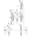
- FIG. 4 is a first flowchart for explaining the operation of the three-dimensional information generation system according to the embodiment.
- 11 is a second flowchart for explaining the operation of the three-dimensional information generation system according to the embodiment.
- 11 is a third flowchart for explaining the operation of the three-dimensional information generation system according to the embodiment.
- FIG. 11 is a first diagram for explaining a method for determining an ideal IR value according to the embodiment.
- FIG. 2 is a second diagram for explaining a method for determining an ideal IR value according to the embodiment.
- 13 is a fourth flowchart for explaining the operation of the three-dimensional information generation system according to the embodiment.
- 13 is a fifth flowchart for explaining the operation of the three-dimensional information generation system according to the embodiment.
- FIG. 11 is a diagram for explaining a feature point according to the embodiment.
- 13 is a sixth flowchart for explaining the operation of the three-dimensional information generation system according to the embodiment.
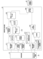
- FIG. 2 is a functional configuration diagram showing an example of a functional configuration of a three-dimensional information generation system according to an embodiment.
- FIG. 2 is a functional configuration diagram showing an example of a functional configuration of a reliability calculation device according to an embodiment.
- 1 is a functional configuration diagram showing an example of a functional configuration of a three-dimensional information creation device according to an embodiment
- 1 is a block diagram showing an example of an internal configuration of a reliability calculation device and a three-dimensional information creation device according to an embodiment.
- FIG. 1 An overview of a three-dimensional information generation system 1 according to an embodiment will be described with reference to FIGS. 1 to 3.
- FIG. 1 An overview of a three-dimensional information generation system 1 according to an embodiment will be described with reference to FIGS. 1 to 3.
- FIG. 1 An overview of a three-dimensional information generation system 1 according to an embodiment will be described with reference to FIGS. 1 to 3.
- FIG. 1 An overview of a three-dimensional information generation system 1 according to an embodiment will be described with reference to FIGS. 1 to 3.
- the three-dimensional information generating system 1 is a first diagram for explaining an overview of a three-dimensional information generating system according to an embodiment.
- the three-dimensional information generating system 1 generates three-dimensional information of a subject S.
- the three-dimensional information generating system 1 includes one or more imaging devices 10.
- the imaging device 10 is a device capable of acquiring a distance image, an IR image, a polarized image, and an RGB image.
- the distance image, the IR image, the polarized image, and the RGB image may have the same optical axis.
- the imaging device 10 has a ToF (Time of Flight) sensor for acquiring a distance image and an IR image, a polarization sensor for acquiring a polarized image, and an image sensor for acquiring an RGB image, and each sensor may be disposed in a position such that the light path of the light incident on the lens is divided so that the light is incident on each sensor.
- ToF Time of Flight
- a polarization sensor for acquiring a polarized image
- an image sensor for acquiring an RGB image
- each sensor may be disposed in a position such that the light path of the light incident on the lens is divided so that the light is incident on each sensor.
- this embodiment is not limited to an example of the case where the light has the same optical axis, and it is sufficient that the distance image, the IR image, the polarized image, and the RGB image have two-dimensional coordinate systems corresponding to each other.
- the imaging device 10 acquires distance information from the imaging device 10 to the subject S, for example, using the ToF method.
- the imaging device 10 acquires distance information to the subject S from multiple points (i.e., from multiple viewpoints) and generates three-dimensional information of the subject S by synthesizing the acquired distance information.
- infrared light is irradiated onto the subject S, and the distance to the subject S is measured based on the time it takes for the reflected light to be received.
- infrared light is irradiated by the ToF sensor, and information regarding the amount of light received within a specified time may be referred to as an IR image.
- the imaging device 10 may continuously capture frame images while moving from one imaging point to another, for example as indicated by the arrow in the figure, to continuously obtain distance information from a plurality of points to the subject S.
- the movement of the imaging device 10 may be determined based on the acceleration, angular velocity, etc. measured by an inertial measurement unit (IMU) (not shown) included in the imaging device 10.
- IMU inertial measurement unit
- different imaging devices 10 may be placed in advance at the two locations shown in the figure, and distance information from the multiple locations to the subject S may be obtained by capturing images of the subject S from each location.
- the three-dimensional information generation system 1 includes multiple imaging devices 10, the number of imaging devices 10 is not limited, and using more imaging devices 10 makes it possible to acquire more information and generate more accurate three-dimensional information.
- FIG. 2 is a second diagram for explaining an overview of the three-dimensional information generation system according to the embodiment.
- This diagram shows an example in which the three-dimensional information generation system 1 generates three-dimensional information using one imaging device 10.
- a marker MK is placed in front of the subject S.
- the marker MK is used to identify the world coordinate system. Therefore, it is preferable that the marker MK be one whose position and orientation can be identified by being imaged by the imaging device 10.
- the marker MK may be, for example, an identification code such as a QR code (registered trademark).
- the marker MK may be, for example, an image showing the identification code printed on a medium such as paper or plastic.
- the imaging device 10 captures the marker MK in addition to the subject S.
- the imaging device 10 may capture the subject S and the marker MK separately (i.e., an image showing the subject S and an image showing the marker MK as separate frame images), or may capture an image showing both the subject S and the marker MK.
- the imaging device 10 captures the subject S from multiple viewpoints after capturing the marker MK.
- a world coordinate system may be obtained with the position where the marker MK is captured as the origin. That is, the three-dimensional information generation system 1 identifies the amount of movement of the imaging device 10 from the point where the marker MK is captured based on the acceleration, angular velocity, etc. measured by an inertial measurement device (not shown), and identifies the point (coordinates and orientation) where the imaging device 10 captured the image. Note that in this embodiment, it is not necessary to use the marker MK, and the world coordinate system may be created by other methods.
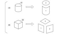
- FIG. 3 is a diagram for explaining a method for generating three-dimensional information by a three-dimensional information generating system according to an embodiment.
- the three-dimensional information generating system 1 calculates the reliability of each pixel and each surface from the acquired distance information of the subject S. The method for calculating the reliability will be described in detail later.
- FIG. 3(A) shows an example in which the subject S is a cylindrical subject S1.
- the three-dimensional information of the subject S1 includes a surface marked with the reference number 1 and a surface marked with the reference number 2.
- the three-dimensional information for each surface is obtained from an image captured from multiple viewpoints by the imaging device 10, the image having a high reliability for that surface.
- the three-dimensional information for each surface may be obtained from different images.
- the three-dimensional information generation system 1 generates the three-dimensional information of the subject S1 by synthesizing the three-dimensional information for each surface obtained from different images.
- FIG. 3(B) shows an example in which subject S is a cubic subject S2.
- the three-dimensional information of subject S2 includes a surface marked with reference numeral 1, a surface marked with reference numeral 2, and a surface marked with reference numeral 3.
- subject S2 three-dimensional information for each surface is obtained from different images, and the three-dimensional information for each surface is synthesized to generate three-dimensional information for subject S2.
- FIG. 4 is a first flowchart for explaining the operation of the three-dimensional information generation system according to the embodiment.
- the figure shows an example of a set of operations performed by the three-dimensional information generation system 1.
- a person who generates three-dimensional information of the subject S by operating the three-dimensional information generation system 1 may be referred to as an operator.
- Step S10 First, if the subject S is made of a transparent material, a polarized light (not shown) is turned on.
- the polarized light is included in the three-dimensional information generation system 1 and is installed in a position where it can illuminate the subject S.
- the polarized light may be provided in the imaging device 10. If it is determined that the subject S is made of a transparent material, for example, the on/off control of the polarized light may be performed manually by an operator. Also, the on/off control of the polarized light may be performed mechanically according to the results of analysis based on the IR image and the polarized image acquired by the imaging device 10.
- Step S12 The imaging device 10 captures an image of the subject S.
- This imaging includes acquiring a distance image, an IR image, a polarized image, and an RGB image.
- images may simply be referred to as images.
- the three-dimensional information generation system 1 generates a reliability map of the captured image.
- the reliability map is information in which reliability is assigned to each coordinate of the image.
- a reliability map is generated for each of multiple images captured successively in time. A method for creating a reliability map will be described later with reference to FIG. 5 etc.
- the three-dimensional information generation system 1 generates three-dimensional information of the subject S by selectively synthesizing suitable distance information based on the created reliability map.
- Step S14 The three-dimensional information generating system 1 displays the generated three-dimensional information (3D model) of the subject S.
- the three-dimensional information of the subject S is displayed, for example, on a display (not shown).
- the three-dimensional information of the subject S may be projected by a predetermined method in a visually recognizable manner. The operator checks the displayed three-dimensional information of the subject S.
- Step S15 The operator checks the displayed three-dimensional information of the subject S and then decides whether or not to end the three-dimensional information generation process. For example, if the operator determines that noise is superimposed on the displayed three-dimensional information and that the three-dimensional shape of the subject S is not adequately represented (i.e., different from the real thing), the operator can continue the three-dimensional information generation process. If it is determined that the three-dimensional information generation process should be ended (i.e., step S15; YES), the process proceeds to step S16. If it is determined that the three-dimensional information generation process should not be ended (i.e., the three-dimensional information generation process should be continued) (i.e., step S15; NO), the process proceeds to step S17.
- Step S16 The three-dimensional information generation system 1 exports the three-dimensional information into the target file format.
- the exported file is stored in a specified storage unit.
- Step S17 When the generation process of the three-dimensional information is continued, the imaging process is performed again by the imaging device 10.
- the imaging process may be performed by moving the position of the imaging device 10, or may be performed without moving the position of the imaging device 10. If the distance information cannot be acquired correctly due to the imaging position, it is preferable to move the position of the imaging device 10, and if the distance information cannot be acquired correctly regardless of the imaging position, it is not necessary to move the position of the imaging device 10. Whether or not the position of the imaging device 10 has been moved may be determined based on, for example, the acceleration, angular velocity, etc. measured by an inertial measurement device (not shown) provided in the imaging device 10.
- step S17 If it is determined that the position of the imaging device 10 has been moved (i.e., step S17; YES), the process proceeds to step S18. If it is determined that the position of the imaging device 10 has not been moved (i.e., step S17; NO), the process proceeds to step S19.
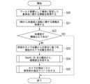
- FIG. 5 is a second flowchart for explaining the operation of the three-dimensional information generation system according to the embodiment. An example of the reliability map generation process will be explained with reference to the same figure.
- the reliability map generation process is the process described above as step S13.
- Step S20 The three-dimensional information generating system 1 acquires information about a reference point that has been set in advance as world coordinates.
- the reference point may be the position of the marker MK described with reference to FIG. 2. If the position of the marker MK has not yet been acquired, the three-dimensional information generating system 1 may instruct the operator to capture an image of the marker MK.
- the three-dimensional information generation system 1 acquires information about acceleration and rotation from an inertial measurement unit (not shown) provided in the imaging device 10.
- Step S22 Here, if the acquired acceleration is equal to or greater than the threshold, camera shake has occurred and the image information may be incorrect (information about the subject S has not been acquired properly). Therefore, if the acquired acceleration is equal to or greater than the threshold (i.e., step S22; YES), the three-dimensional information generation system 1 decides not to use the image in the three-dimensional information generation process and terminates the reliability map generation process. If the acquired acceleration is not equal to or greater than the threshold (i.e., step S22; NO), the three-dimensional information generation system 1 continues the reliability map generation process and proceeds to step S23.
- the three-dimensional information generation system 1 determines the current camera position based on the displacement from the previous camera position and the information on the reference point acquired in step S20.
- the previous camera position may be the camera position at which the frame image obtained the instant before the frame image currently being processed among the consecutive frame images was captured.
- the current camera position may be the camera position at which the frame image currently being processed was captured.
- the three-dimensional information generating system 1 creates a reliability when the subject S is imaged from the determined camera position. Specifically, the three-dimensional information generating system 1 creates a reliability map based on the distance image, the IR image, and the polarized image. Details of a specific method for creating the reliability map will be described later with reference to FIG. 6, etc.
- Step S25 The three-dimensional information generation system 1 divides the subject S into parts for each camera position based on the created reliability map. Details of the part division process for the subject S will be described later with reference to FIG. 11, etc.
- FIG. 6 is a third flowchart for explaining the operation of the three-dimensional information generation system according to the embodiment. An example of the detailed process of the reliability map generation process will be explained with reference to the same figure. The detailed process of the reliability map generation process is, in other words, the process described above as step S24.
- Step S30 the three-dimensional information generating system 1 judges whether the distance value and IR value of each coordinate are valid based on the distance image and the IR image. The judgment of whether the value is valid may be made based on whether the value is within a predetermined threshold.
- the distance value and IR value of each coordinate are not valid, that is, when they are abnormal values, examples of which include when the target pixel is a so-called dead pixel, or when noise is superimposed and the value becomes abnormal.
- the three-dimensional information generating system 1 advances the process to step S31.
- the distance value and IR value of each coordinate are not valid (i.e., step S30; NO)
- the three-dimensional information generating system 1 advances the process to step S31.
- the three-dimensional information generating system 1 calculates an ideal IR value (amount of received light) based on the distance value for each pixel.
- the IR value also differs as the distance to the subject S changes. Specifically, the amount of received light decreases as the distance to the subject S increases, and increases as the distance to the subject S decreases. Also, if the distance to the subject S is constant, the amount of received light (IR value) also differs depending on the infrared reflectance of the subject S. Specifically, the amount of received light decreases as the infrared reflectance of the subject S decreases, and increases as the infrared reflectance of the subject S increases.
- the characteristic that the IR value differs depending on the distance and the infrared reflectance of the subject S is used to determine an ideal IR value based on the distance value to the subject S, and the reliability is calculated based on the ideal IR value and the actual IR value.
- the reliability may be the ratio of the actual IR value to the ideal IR value.
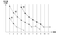
- FIG. 7 is the first diagram for explaining how to find the ideal IR value according to the embodiment.
- the horizontal axis indicates distance
- the vertical axis indicates IR value (amount of received light).
- This diagram also shows measurement results for three subjects with different infrared reflectance as lines W1, W2, and W3.
- Line W1 has a lower infrared reflectance
- line W3 has a higher infrared reflectance.
- points shown in black are points where the IR value is sufficient.
- points shown in white are points where the IR value is insufficient.
- the information shown in the figure is information obtained by actual measurement using an evaluation chart.
- the evaluation chart may be a gray chart having a plurality of different gray levels.
- the line W1 is a chart having a gray level closer to black
- the line W3 is a chart having a gray level closer to white.
- the figure shows an example of a case where an evaluation chart having three infrared reflectances is used, but if a gray chart with 16 gradations is used, for example, 16 lines will be drawn.
- the information shown in the figure is actually measured, but this embodiment is not limited to an example of a case where information is obtained by actual measurement, and it is sufficient if the correspondence between distance and IR value can be obtained by some method.
- distance values 1 through 11 indicate relative distances (i.e., without units) to simplify the explanation. When performing actual measurements, actual distance values may be used. Furthermore, the distance values do not need to be spaced at equal intervals, as long as information exists for multiple points. For example, in a range where the change in the amount of received light is small, the intervals do not need to be the same as in a range where the change in the amount of received light is large.
- the three-dimensional information generating system 1 acquires correspondence information between distance and amount of received light as shown in the figure by conducting experiments or the like, and stores the acquired information in a storage unit. Note that this embodiment is not limited to an example of acquiring correspondence information between distance and amount of received light by experiments or the like, and the correspondence information may be acquired by simulation or the like.
- the three-dimensional information generation system 1 calculates an ideal IR value for each pixel based on the acquired distance image.
- the three-dimensional information generation system 1 selects two pieces of data that are closest to the distance value at the coordinates to be determined for reliability from among the data stored in advance.
- data with a high IR value is selected.
- data with a low infrared reflectance is selected. For example, in the example shown in the figure, a search is performed to see if there is suitable data on the line W1 with the lowest infrared reflectance, and if no suitable data is found, a search is performed to see if there is suitable data on the line W2 with the next lowest infrared reflectance after the line W1.
- the distance value of the pixel to be processed is 3.5, there is no suitable data on the line W1 (white dots), but there are two suitable pieces of data on the line W2 (black dots). More specifically, when the distance value of the pixel to be processed is 3.5, data with a distance value of 3 and data with a distance value of 4 on the line W2 are selected.
- the reflectance of the subject S for which three-dimensional information is to be generated is known in advance, data close to that reflectance may be selected.
- the reflectance of the subject S may be selected by the operator, or may be determined based on an IR image, an RGB image, or the like captured by the imaging device 10.
- FIG. 8 is a second diagram for explaining how to calculate the ideal IR value according to the embodiment.
- the horizontal axis indicates distance
- the vertical axis indicates IR value (amount of received light).
- two pieces of data selected based on the distance value are shown as points P1 and P2.
- point P1 is, for example, a point on line W2 whose distance value is 3
- point P2 is, for example, a point on line W2 whose distance value is 4.
- line L1 is a line segment connecting points P1 and P2.
- the ideal IR value (point marked CurrentRecommendIR in the diagram) is calculated based on the distance value (point marked CurrentDepth in the diagram) at the coordinates to be calculated for the ideal IR value, and line segment L1.
- the three-dimensional information generation system 1 calculates the reliability based on the obtained ideal IR value.
- the reliability may be, for example, the ratio between the ideal IR value at the coordinates for which the reliability is to be calculated and the distance value at the coordinates for which the reliability is to be calculated. If the actual IR value is greater than the ideal IR value, the upper limit of the reliability may be set to 100%, and values exceeding 100% may be truncated.
- step S30 determines that the pixel value is not a valid value, the reliability is set to 0.
- Step S34 The three-dimensional information generation system 1 stores the reliability calculated in steps S31 and S32 for each pixel.
- information having reliability for each pixel on the two-dimensional coordinate system is also referred to as a reliability map.
- Step S35 The three-dimensional information generation system 1 removes from the distance image and IR image any pixels in the created reliability map whose reliability is lower than a predetermined threshold value.
- Step S36 The three-dimensional information generating system 1 assigns information based on the polarized image to the reliability map.
- the assignment of information based on the polarized image will be described later with reference to FIG. 9.
- specular reflection may occur, and in such cases, the distance information may be inaccurate.
- a specular reflection flag is assigned to pixels that are estimated to be specularly reflecting.
- a transparent material may be used, and in such cases, the distance information may also be inaccurate.
- a transparent flag is assigned to pixels that are estimated to be using a transparent material.
- Step S37 The three-dimensional information generation system 1 removes pixels that have at least one of the specular reflection flag or the transparent flag assigned from the distance image and the IR image, regardless of their reliability.
- the three-dimensional information generating system 1 performs a process of correcting unevenness for each surface of the subject S. Specifically, the three-dimensional information generating system 1 identifies the surface of the subject S, and corrects unevenness by uniformly rewriting distance values along the surface to smooth values. Rewriting distance values may mean complementing pixel values removed from the distance image and IR image based on pixel values in the vicinity of the pixel. Rewriting distance values may also mean correcting pixel values on the same surface based on pixel values in the vicinity.
- FIG. 9 is a fourth flowchart for explaining the operation of the three-dimensional information generation system according to the embodiment. An example of the process of adding information based on a polarized image will be explained with reference to the same figure. Adding information based on a polarized image is the process described above as step S36.
- Step S40 First, a polarized image is captured by the imaging device 10. This polarized image corresponds to the distance image used to create the reliability map in the above description.
- Step S41 The three-dimensional information generation system 1 separates the specular and diffuse reflection components based on the acquired polarized image.
- DoLP Degree of Linear Polarization
- the three-dimensional information generation system 1 assigns a specular flag to coordinates with a large DoLP.
- Step S42 the three-dimensional information generating system 1 determines the polarization direction from the angle of linear polarization (AoLP; Angle of Linear Polarization).
- the three-dimensional information generating system 1 identifies the surface of the subject S and the surface normal based on the determined polarization direction and DoLP.
- the identified surfaces are labeled (clustered). Surfaces estimated to be the same in multiple consecutive images are assigned the same label (class).
- the closest one may be selected by performing normal estimation based on tangential depth, based on information from past frame images and information from the current frame image.
- Step S43 The three-dimensional information generation system 1 performs noise removal on the identified surfaces.
- Step S44 the three-dimensional information generating system 1 uses polarized light to determine whether or not the subject S is made of a transparent material. However, some imaging devices 10 have polarized light and some do not. Therefore, the three-dimensional information generating system 1 first determines whether or not the imaging device 10 has polarized light. If the imaging device 10 has polarized light (i.e., step S44; YES), the process proceeds to step S45 to perform a process to determine whether or not the material is transparent. If the imaging device 10 does not have polarized light (i.e., step S44; NO), the process ends.
- the three-dimensional information generating system 1 determines whether the subject S is a transparent material. Since many transparent materials have changing optical properties, it is possible to determine whether the material is a transparent material by irradiating it with polarized light. The determination of whether the material is a transparent material may be performed for each pixel or for each surface. Specifically, a PassiveIR image is used to determine whether the material is a transparent material. Specifically, the PassiveIR image may be an image obtained by capturing ambient light without irradiating infrared light using a ToF sensor. In the case of an imaging device 10 having a polarized light, the influence of reflected light from the polarized light appears in the PassiveIR image. Therefore, the three-dimensional information generating system 1 determines whether the material is a transparent material by determining the reflection intensity from the light source based on the PassiveIR image.
- Step S46 If the three-dimensional information generation system 1 determines that the material is transparent (i.e., step S46; YES), the process proceeds to step S47. If the three-dimensional information generation system 1 does not determine that the material is transparent (i.e., step S46; NO), the process ends.
- the three-dimensional information generation system 1 assigns a transparent flag to each pixel or surface determined to be a transparent material.
- the change in optical characteristics may only appear at the outline.
- the periphery of the edge of the surface may be determined to be a transparent material, and the center of the surface may not be determined to be a transparent material. Therefore, a transparent flag may be assigned to all pixels on the same surface as a surface that has a pixel determined to be a transparent material.
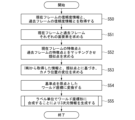
- FIG. 10 is a fifth flowchart for explaining the operation of the three-dimensional information generation system according to the embodiment.
- An example of the parting process for each camera viewpoint will be explained with reference to the same figure.
- the parting process for each camera viewpoint is the process described above as step S25.
- Step S50 First, the three-dimensional information generation system 1 obtains a reliability map for the current frame and a reliability map for the past frame.
- Step S51 the three-dimensional information generation system 1 finds surface elements for each of the current frame and the past frame. Whether or not an element is a surface is determined based on a distance image corresponding to the acquired reliability map.
- Step S52 The three-dimensional information generation system 1 identifies feature points based on the distance image. Feature points are characteristic points among the points that make up a surface. For example, four feature points are identified for each surface.
- the three-dimensional information generation system 1 identifies the feature points of the current frame and the feature points of the previous frame. The three-dimensional information generation system 1 finds similarities by matching the identified feature points of the current frame with the feature points of the previous frame. Details of the feature points will be described with reference to FIG. 11.
- FIG. 11 is a diagram for explaining feature points according to an embodiment.
- the subject S has at least surfaces SF1, SF2, and SF3.
- the figure shows four feature points for surface SF1.
- surface SF1 is rectangular, and vertices P11 to P14 of the rectangle are identified as feature points.
- the number of feature points may be as many as necessary to identify the surface, and is not limited to the example of four points as shown.
- the number of feature points may be different for each surface. For example, a surface having a complex shape may have a large number of feature points.
- FIG. 11(B) is a diagram for explaining matching between feature points of the current frame and feature points of a past frame.
- the imaging device 10 captures images of the subject S from multiple positions.
- the imaging device 10 captures images of the subject S from a position indicated by reference numeral 10-1 and a position indicated by reference numeral 10-2. Regardless of the position from which the image is captured, the feature points of the subject S are identified.
- the three-dimensional information generation system 1 finds similarities by matching the identified feature points of the current frame with the feature points of the past frames.
- Step S53 the three-dimensional information generation system 1 determines the displacement of the imaging device 10 based on the information acquired from the inertial measurement unit provided in the imaging device 10 and the similarity determined in step S52.
- the displacement of the imaging device 10 is the displacement from the point at which the target past frame was captured to the point at which the current frame was captured.
- Step S54 The three-dimensional information generating system 1 converts the three-dimensional information of the subject S in the current frame into coordinates of a world coordinate system with the reference point as the origin.
- the coordinates of the world coordinate system are those obtained in step S20.
- the three-dimensional information generation system 1 searches for highly reliable frame images in the target frame images on a label-by-label basis (i.e., face-by-face basis), and synthesizes three-dimensional information of the subject S using the three-dimensional information of the relevant faces.
- the three-dimensional information generation system 1 extracts highly reliable three-dimensional information for each face from different frame images, and generates three-dimensional information of the subject S by synthesizing the extracted three-dimensional information in the world coordinate system.
- FIG. 12 is a sixth flowchart for explaining the operation of the three-dimensional information generation system according to the embodiment. A detailed example of the three-dimensional information synthesis process will be explained with reference to the same figure.
- the three-dimensional information synthesis process is the process described above as step S55.
- Step S60 The three-dimensional information generating system 1 determines whether or not the label included in the target frame image is a new label.
- a new label is a label that has not appeared so far while the three-dimensional information generating system 1 is processing multiple frame images. If the label is new (i.e., step S60; YES), the three-dimensional information generating system 1 proceeds to step S61. If the label is not new (i.e., step S60; NO), the three-dimensional information generating system 1 proceeds to step S62.
- Step S61 If the label is new, the three-dimensional information generation system 1 places the three-dimensional information of the surface to which the label is assigned in the world coordinate system.
- Step S62 If the label is not new, the three-dimensional information generation system 1 compares the reliability of faces having the same label in the current frame and the previous frame.
- the comparison of reliability may be a comparison of the reliability of faces calculated based on the average reliability of each coordinate included in the face, etc.
- Step S63 If the reliability of faces with the same label is the same in the current frame and the previous frame (i.e., step S63; YES), the three-dimensional information generation system 1 advances the process to step S64. If the reliability of faces with the same label is not the same in the current frame and the previous frame (i.e., step S63; NO), the three-dimensional information generation system 1 advances the process to step S65.
- Step S64 If the reliability of faces with the same label is the same in the current frame and the previous frame, the label of the face with the larger area is placed.
- the face with the larger area is estimated to be an image of the face captured from the front, and is estimated to be more reliable information.
- Step S65 If the reliability of faces with the same label is not the same in the current frame and the previous frame, the label with the higher reliability is placed. This is because it is estimated that the higher the reliability, the less noise there is and the more accurately the 3D information is obtained.
- FIG. 13 is a functional configuration diagram showing an example of the functional configuration of a three-dimensional information generation system according to an embodiment. With reference to the diagram, an example of the functional configuration of the three-dimensional information generation system 1 will be described.
- the three-dimensional information generation system 1 includes an imaging device 10, an inertial measurement unit 20, a reliability calculation device 30, a reliability storage unit 40, and a three-dimensional information creation device 50.
- the imaging device 10 captures an image of a subject S.
- the images captured by the imaging device 10 include a distance image, an IR image, a polarized image, and an RGB image. It is preferable that the two-dimensional coordinates of these images correspond to each other.
- the imaging device 10 captures images continuously.
- the continuous images captured by the imaging device 10 can also be called frame images.
- the imaging device 10 captures images at a predetermined frame rate.
- the predetermined frame rate may be, for example, 1 FPS (frames per second), or 24 FPS.
- the inertial measurement unit 20 measures the motion of the imaging device 10.
- the inertial measurement unit 20 may be configured as one of the components of the imaging device 10.
- the inertial measurement unit 20 includes an acceleration sensor and a gyro sensor (not shown), and detects acceleration and angular velocity in three axes.
- the reliability calculation device 30 calculates the reliability for each coordinate for each frame image based on the image captured by the imaging device 10 and the acceleration and angular velocity acquired by the inertial measurement device 20. Information regarding the reliability for each coordinate in each image is also referred to as a reliability map. The specific configuration of the reliability calculation device 30 will be described later with reference to FIG. 14.
- the reliability storage unit 40 stores the reliability for each image calculated by the reliability calculation device 30. It can also be said that the reliability storage unit 40 stores a reliability map for multiple images (frame images) that are consecutive in time.
- the three-dimensional information creation device 50 creates three-dimensional information of the subject S using multiple reliability maps calculated by the reliability calculation device 30 and stored in the reliability storage unit 40.
- the three-dimensional information creation device 50 identifies high reliability parts for each configuration (e.g., surface) of the subject S by cross-referencing multiple temporally consecutive reliability maps.
- the three-dimensional information creation device 50 creates three-dimensional information of the subject S by compositing the identified high reliability parts into the world coordinate system.
- the reliability calculation device 30 includes a polarized image acquisition unit 311, an IR image acquisition unit 312, a distance image acquisition unit 313, a reliability calculation unit 314, a calibration information storage unit 315, a mirror flag assignment unit 316, a surface identification unit 317, a transparent material determination unit 318, a noise removal unit 319, a transparent flag assignment unit 320, an inertia information acquisition unit 331, an acceleration threshold information storage unit 332, a comparison unit 333, a displacement calculation unit 334, and a reliability output unit 340.
- each of these functional units is realized, for example, using an electronic circuit.
- each functional unit may include a storage means such as a semiconductor memory or a magnetic hard disk device inside as necessary.
- Each function may also be realized by a computer having a CPU (Central Processing Unit) and software.
- the reliability calculation device 30 may also be provided by other devices (e.g., the three-dimensional information creation device 50) provided in the three-dimensional information generation system 1.
- the polarized image acquisition unit 311 acquires a polarized image captured by the imaging device 10.
- the polarized image has polarization information of the subject S at each coordinate in the two-dimensional coordinate system.
- the IR image acquisition unit 312 acquires an IR image captured by the imaging device 10.
- the IR image has information about the amount of infrared light received at each coordinate in a two-dimensional coordinate system.
- the IR image may be an IR image acquired by using a ToF sensor to capture the amount of infrared light (i.e., ambient light) in a state where no irradiation light is being emitted.
- the distance image acquisition unit 313 acquires a distance image (depth image) captured by the imaging device 10.
- the distance image has distance information from the imaging device 10 to the subject S at each coordinate in a two-dimensional coordinate system.
- the distance information at each coordinate may be referred to as a distance value or a depth value.
- the coordinates of the polarized image, IR image, and distance image correspond to each other. It is preferable that the number of pixels (resolution) of the polarized image, IR image, and distance image are the same, but this is not a limitation to the example where they are the same. In other words, the coordinates of the polarized image, IR image, and distance image do not need to correspond one-to-one, but may correspond to each other.
- the imaging device 10 captures images of the subject S from multiple different points.
- the imaging device 10 may continue capturing images of the subject S from different imaging points.
- a polarized image captured from the first point may be referred to as a first polarized image
- an IR image captured from the first point may be referred to as a first IR image
- a distance image captured from the first point may be referred to as a first distance image.
- a polarized image captured from a second point different from the first point may be referred to as a second polarized image
- an IR image captured from the second point may be referred to as a second IR image
- a distance image captured from the second point may be referred to as a second distance image.
- the reliability calculation unit 314 acquires an IR image from the IR image acquisition unit 312, and acquires a distance image from the distance image acquisition unit 313.
- the reliability calculation unit 314 calculates the reliability for each pixel based on the acquired IR image and distance image.
- the reliability calculation is performed by referring to the corresponding data.
- the corresponding data is data obtained by measuring in advance the correspondence relationship between the distance to the evaluation chart and the amount of received light using an evaluation chart with a specific reflectance.
- the calibration information storage unit 315 stores correspondence data that has been measured in advance.
- the correspondence data can also be said to be the correspondence between distance and IR value measured using an evaluation chart.
- the evaluation chart used for measurement is preferably a gray chart having a plurality of different gray levels.
- the correspondence data is data in which distance and the amount of received light are associated with each other for each gray level.
- FIG. 15 is a functional configuration diagram showing an example of the functional configuration of the reliability calculation unit according to the embodiment. With reference to the diagram, an example of the functional configuration of the reliability calculation unit 314 will be described.
- the reliability calculation unit 314 includes a selection unit 3141, an ideal light amount calculation unit 3142, and a calculation unit 3143.
- the selection unit 3141 acquires a distance image from the distance image acquisition unit 313.
- the selection unit 3141 selects a suitable gray level from among multiple gray levels based on distance information at each coordinate of the acquired distance image. Selecting a gray level also means selecting data according to the infrared reflectance of the subject S.
- the corresponding information stored in the calibration information storage unit 315 is referenced for selecting a gray level. Note that if the infrared reflectance of the subject S is known, the selection unit 3141 may select a gray level according to the infrared reflectance of the subject S.
- the ideal light amount calculation unit 3142 calculates the ideal light amount at each coordinate based on the data selected by the selection unit 3141 and the distance value of the distance image acquired by the distance image acquisition unit 313. The calculation of the ideal light amount is performed by referring to the corresponding data stored in the calibration information storage unit 315.
- the calculation unit 3143 calculates the reliability (i.e., reliability map) at each coordinate based on the result of comparing the ideal light amount obtained by the calculation by the ideal light amount calculation unit 3142 at each coordinate with the amount of infrared light received contained in the IR image acquired by the IR image acquisition unit 312.
- the reliability map calculated by the reliability calculation unit 314 is output to the mirror flag assignment unit 316.
- the mirror surface flag assigning unit 316 acquires a polarized image from the polarized image acquisition unit 311, and acquires a reliability map from the reliability calculation unit 314.
- the mirror surface flag assigning unit 316 assigns a mirror surface flag to the reliability map for each coordinate based on the acquired polarized image.
- the mirror surface flag assigning unit 316 may assign a mirror surface flag to coordinates with a large DoLP.
- the surface identification unit 317 acquires a polarized image from the polarized image acquisition unit 311, and identifies the surface of the subject S based on the acquired polarized image.
- the surface identification unit 317 may determine the polarization direction based on the AoLP, and identify the surface of the subject S based on the determined polarization direction and the DoLP.
- the surface identification unit 317 also performs labeling (clustering) for each identified surface.
- the transparent material determination unit 318 acquires a polarized image from the polarized image acquisition unit 311, and determines whether or not the material is transparent based on the acquired polarized image.
- the determination of whether or not the material is transparent is preferably performed for each pixel.
- the result of the determination of whether or not the material is transparent performed for each pixel may be reflected on the surface identified by the surface identification unit 317.
- the noise removal unit 319 obtains labeling information for each surface from the surface identification unit 317, and obtains information about the reliability map after the mirror surface flag has been assigned from the mirror surface flag assignment unit 316.
- the noise removal unit 319 removes distance information at coordinates to which a polarization flag has been assigned, from the distance information that the distance image has at each coordinate.
- the noise removal unit 319 also smoothes out the unevenness of the surface by complementing the removed distance information within the range identified as a surface by the surface identification unit 317.
- the transparent flag assigning unit 320 obtains the reliability map after noise has been removed from the noise removal unit 319, and obtains information on the result of the determination of whether or not the material is transparent from the transparent material determination unit 318.
- the transparent flag assigning unit 320 assigns a transparent flag to coordinates determined to be transparent materials among the coordinates of the reliability map after noise has been removed.
- the transparent flag assigning unit 320 outputs the reliability map after the transparent flag has been assigned to the reliability output unit 340.
- the inertial information acquisition unit 331 acquires information relating to the movement of the imaging device 10 from the inertial measurement device 20. Specifically, the distance image acquisition unit 313 acquires information relating to the acceleration and angular velocity in three axes. The inertial information acquisition unit 331 may also acquire information relating to the timing at which an image was captured by the imaging device 10. By acquiring information relating to the timing at which an image was captured by the imaging device 10, the inertial information acquisition unit 331 acquires information relating to the movement of the imaging device 10 from when the first image is captured by the imaging device 10 to when the second image is captured.
- the acceleration threshold information storage unit 332 stores information related to the acceleration threshold.
- the acceleration threshold is the limit of acceleration at which an image is recognized as normal. In other words, if the acceleration acquired by the inertial information acquisition unit 331 is equal to or greater than the acceleration threshold, it is estimated that the image is not normal (for example, that the image is blurred).
- the comparison unit 333 compares the acceleration acquired by the inertia information acquisition unit 331 with the acceleration threshold value stored in the acceleration threshold value information storage unit 332.
- the comparison unit 333 outputs the comparison result to the displacement calculation unit 334.
- the comparison result indicates whether or not the image is normal.
- the displacement calculation unit 334 acquires information relating to the movement of the imaging device 10 between frame images from the inertial information acquisition unit 331, and acquires information relating to the determination result as to whether the image is normal or not from the comparison unit 333. If the image is normal, the displacement calculation unit 334 calculates the displacement of the imaging device 10 between the frame images. The displacement calculation unit 334 outputs information relating to the displacement of the imaging device 10 between the frame images obtained as a result of the calculation to the reliability output unit 340. Note that if the image is not normal, the comparison unit 333 or the displacement calculation unit 334 may notify the reliability calculation unit 314, etc., to stop the calculation process of the reliability map.
- the reliability output unit 340 acquires a reliability map from the transparent flag assignment unit 320, and acquires information related to the displacement of the image capture device 10 from the displacement calculation unit 334.
- the reliability output unit 340 associates the acquired information and stores it in the reliability storage unit 40.
- the reliability storage unit 40 stores the reliability map and information related to the displacement of the image capture device 10 in association with each other for each frame image. Note that the reliability storage unit 40 may also store an RGB image or a distance image corresponding to the reliability map in association with the reliability map, in addition to the reliability map and the information related to the displacement of the image capture device 10.
- FIG. 16 is a functional configuration diagram showing an example of the functional configuration of a three-dimensional information creation device according to an embodiment.
- the three-dimensional information creation device 50 includes a reliability information acquisition unit 51, a surface element identification unit 52, a similarity calculation unit 53, and a synthesis unit 55.
- Each of these functional units is realized, for example, using electronic circuits.
- each functional unit may include internal storage means such as a semiconductor memory or a magnetic hard disk device as necessary.
- each function may be realized by a computer having a CPU and software.
- the three-dimensional information creation device 50 generates three-dimensional information of the subject S based on the reliability of each of the multiple frame images stored in the reliability storage unit 40 and information related to the displacement of the imaging device 10. Specifically, the three-dimensional information creation device 50 compares the reliability at a first time point with the reliability at a second time point, and creates three-dimensional information based on the distance image with a high reliability. The three-dimensional information creation device 50 can generate highly reliable three-dimensional information by selectively using highly reliable distance information from the multiple frame images.
- the reliability information acquisition unit 51 acquires the reliability map stored in the reliability storage unit 40. In addition, the reliability information acquisition unit 51 acquires information related to the displacement of the imaging device 10 and information related to the RGB image, which are associated with the reliability map.
- the surface element identification unit 52 identifies surface elements based on a distance image corresponding to the acquired reliability map.
- the surface elements may be surfaces whose distance information is continuous (surfaces whose distance information is not discrete), for example.
- the surface element identification unit 52 also identifies feature points for identifying the surfaces.
- the similarity calculation unit 53 calculates similarities based on feature points in the current frame image and feature points in the past frame images. By calculating the similarities, it becomes possible to match the current frame image with the past frame images.
- the synthesis unit 55 selectively extracts distance information about the surfaces from the most reliable frame image among the multiple frame images according to the matching results, and generates three-dimensional information of the subject S by synthesizing the distance information about the extracted surfaces. The generated three-dimensional information is presented to the operator.
- FIG. 17 is a block diagram showing an example of the internal configuration of the reliability calculation device 30 and the three-dimensional information creation device 50 according to this embodiment.
- the figure shows the internal configuration of either the reliability calculation device 30 or the three-dimensional information creation device 50.
- Both the reliability calculation device 30 and the three-dimensional information creation device 50 may have the internal configuration shown in the figure as a hardware configuration.
- At least some of the functions of the reliability calculation device 30 and the three-dimensional information creation device 50 can be realized using a computer.
- the computer is configured to include a central processing unit 901, a RAM 902, an input/output port 903, input/output devices 904 and 905, etc., and a bus 906.
- the computer itself can be realized using existing technology.
- the central processing unit 901 executes instructions included in a program read from the RAM 902, etc.
- the central processing unit 901 writes data to the RAM 902, reads data from the RAM 902, and performs arithmetic operations and logical operations according to each instruction.
- the RAM 902 stores data and programs. Each element included in the RAM 902 has an address and can be accessed using the address. RAM is an abbreviation for "random access memory.”
- the input/output port 903 is a port through which the central processing unit 901 exchanges data with external input/output devices.
- the input/output devices 904 and 905 are input/output devices.
- the input/output devices 904 and 905 exchange data with the central processing unit 901 via the input/output port 903.
- the bus 906 is a common communication path used within the computer.
- the central processing unit 901 reads and writes data in the RAM 902 via the bus 906.
- the central processing unit 901 accesses the input/output port via the bus 906.
- the reliability calculation device 30 includes the distance image acquisition unit 313 to acquire a distance image having distance information at each coordinate of the two-dimensional coordinates, includes the IR image acquisition unit 312 to acquire an IR image having information corresponding to the distance image and information on the amount of infrared light received at each coordinate of the distance image, includes the ideal light amount calculation unit 3142 to calculate an ideal light amount based on the distance information at each coordinate of the acquired distance image by referring to the corresponding data, which is data in which the correspondence relationship between the distance and the amount of received light is measured in advance using an evaluation chart having a specific reflectance, and includes the calculation unit 3143 to calculate the reliability at each coordinate based on the result of comparing the ideal light amount obtained by calculation with the amount of infrared light received included in the IR image.
- the reliability calculation device 30 can calculate the reliability of the distance value for each pixel.
- the reliability calculation device 30 can generate three-dimensional information based on the reliability calculated by the reliability calculation device 30, it is possible to generate three-dimensional information of the subject excluding inaccurate distance values, and therefore it is possible to generate highly accurate three-dimensional information that excludes abnormal values due to the influence of noise, etc.
- the evaluation chart is a gray chart having a plurality of different gray levels
- the corresponding data is data in which the distance and the amount of received light are associated with each other for each gray level.
- the reliability calculation device 30 selects a suitable gray level from among the plurality of gray levels based on the distance information at each coordinate of the acquired distance image, and the ideal light amount calculation unit 3142 calculates the ideal light amount based on the data of the gray level selected by the selection unit 3141.
- the amount of received light differs depending on the infrared reflectance of the subject S.
- the reliability calculation device 30 the reliability is calculated by comparing the ideal light amount for each infrared reflectance measured in advance with the light amount obtained by imaging. Therefore, according to this embodiment, the reliability can be calculated with high accuracy.
- the three-dimensional information creation device 50 creates three-dimensional information using the reliability calculation device 30 as described above.
- the distance image acquisition unit 313 acquires a first distance image having distance information from a first point to the subject, and a second distance image having distance information from a second point, which is different from the first point, to the subject, and the IR image acquisition unit 312 acquires a first IR image corresponding to the first distance image and a second IR image corresponding to the second distance image.
- the three-dimensional information creation device 50 compares the reliability based on the first distance image and the first IR image with the reliability based on the second distance image and the second IR image, and creates three-dimensional information based on the distance image with a high reliability. Therefore, the three-dimensional information creation device 50 can generate three-dimensional information of the subject based on distance information with a high reliability, and can generate highly accurate three-dimensional information that eliminates abnormal values due to the influence of noise, etc.
- the three-dimensional information creation device 50 further includes a polarized image acquisition unit 311 to acquire a polarized image that corresponds to the distance image and has the polarization information of the subject at each coordinate of the distance image, a mirror flag assignment unit 316 to assign a mirror flag to each coordinate based on the acquired polarized image, a noise removal unit 319 to remove distance information at coordinates to which a mirror flag is assigned from the distance information that the distance image has at each coordinate, and a surface identification unit 317 to identify a surface based on the acquired polarized image.
- a polarized image acquisition unit 311 to acquire a polarized image that corresponds to the distance image and has the polarization information of the subject at each coordinate of the distance image
- a mirror flag assignment unit 316 to assign a mirror flag to each coordinate based on the acquired polarized image
- a noise removal unit 319 to remove distance information at coordinates to which a mirror flag is assigned from the distance information that the distance image has at each coordinate
- the three-dimensional information creation device 50 creates three-dimensional information by smoothing the unevenness of the surface by complementing the removed distance information within the range identified as the surface. Therefore, according to this embodiment, accurate three-dimensional information of the subject S can be generated even if the subject S has a material that the ToF sensor has difficulty detecting, such as a mirror surface.
- each device provided in the three-dimensional information generation system 1 in the above-mentioned embodiment may be realized by recording a program for realizing these functions on a computer-readable recording medium, and having a computer system read and execute the program recorded on this recording medium.
- the "computer system” referred to here includes hardware such as the OS and peripheral devices.
- “computer-readable recording medium” refers to portable media such as flexible disks, optical magnetic disks, ROMs, and CD-ROMs, as well as storage units such as hard disks built into computer systems.
- “computer-readable recording medium” may also include devices that dynamically store programs for a short period of time, such as communication lines when transmitting programs via networks such as the Internet or communication lines such as telephone lines, and devices that store programs for a certain period of time, such as volatile memory within a computer system that serves as a server or client in such cases.
- the above-mentioned programs may be ones that realize some of the functions described above, or may be ones that can realize the functions described above in combination with programs already recorded in the computer system.
- 1...3D information generation system 10...imaging device, 20...inertial measurement device, 30...reliability calculation device, 40...reliability memory unit, 50...3D information creation device, 311...polarized image acquisition unit, 312...IR image acquisition unit, 313...distance image acquisition unit, 314...reliability calculation unit, 315...calibration information memory unit, 316...mirror flag assignment unit, 317...surface identification unit, 318...transparent material determination unit, 319... noise removal unit, 320... transparency flag assignment unit, 331... inertia information acquisition unit, 332... acceleration threshold information storage unit, 333... comparison unit, 334... displacement calculation unit, 340... reliability output unit, 3141... selection unit, 3142... ideal light amount calculation unit, 3143... calculation unit, 51... reliability information acquisition unit, 52... surface element identification unit, 53... similarity calculation unit, 55... synthesis unit, S... subject, MK... marker
Landscapes
- Engineering & Computer Science (AREA)
- Physics & Mathematics (AREA)
- General Physics & Mathematics (AREA)
- Radar, Positioning & Navigation (AREA)
- Remote Sensing (AREA)
- Theoretical Computer Science (AREA)
- Software Systems (AREA)
- Electromagnetism (AREA)
- Multimedia (AREA)
- Computer Networks & Wireless Communication (AREA)
- Geometry (AREA)
- Computer Graphics (AREA)
- Signal Processing (AREA)
- Computer Vision & Pattern Recognition (AREA)
- Length Measuring Devices By Optical Means (AREA)
- Measurement Of Optical Distance (AREA)
- Optical Radar Systems And Details Thereof (AREA)
Abstract
正確な三次元情報を生成するため、画素ごとの測距値の信頼度を計算することを課題とする。 信頼度計算装置は、距離画像取得部(313)と、距離画像の各座標における赤外光の受光量についてのIR画像取得部(312)と、特定の反射率を有する評価用チャートを用いて距離と受光量との対応関係を予め測定した対応データを参照し、取得した距離画像の各座標における距離情報に基づく理想光量を計算する理想光量計算部(3142)と、理想光量と赤外線の受光量とを比較した結果に基づき、各座標における信頼度を算出する算出部(3143)とを備える。評価用チャートは複数のグレーレベルを有するグレーチャートであり、距離画像の各座標における距離情報に基づき好適なグレーレベルを選択する選択部(3141)を更に有し、選択されたグレーレベルのデータに基づき理想光量を計算する。
Description
本発明は、信頼度計算装置、三次元情報作成装置及び信頼度計算方法に関する。
本願は、2023年6月7日に日本に出願された特願2023-093856について優先権を主張し、その内容をここに援用する。
本願は、2023年6月7日に日本に出願された特願2023-093856について優先権を主張し、その内容をここに援用する。
従来、対象物に向けて測距光を照射し、測定対象物に反射した反射光を受光し、光を照射してから受光するまでの時間を測定することにより、対象物までの距離を算出する方法があった。これらの測距方法は、ToF(Time of Flight)方式として広く知られている。このようなToF方式による測距技術を用いて、多視点から被写体までの距離を観測し、多視点から観測された被写体までの距離情報を合成することにより、被写体の三次元情報を生成する技術があった(例えば、特許文献1を参照)。
ToF方式による測距技術を用いた場合の仕組み上の制約として、ショットノイズによる確率誤差がある。また、近赤外を吸収しやすい素材、又は赤外線を透過しやすい素材を被写体とする場合、ToF方式による測距技術によれば、被写体に照射した測距光が正確に反射されず、測距値が不正確となってしまう問題があった。さらに、ToF方式による測距技術によれば、マルチパスの光経路差の問題により、測距値が不正確となってしまう問題があった。
不正確な測距値を含む距離画像に基づき被写体の三次元情報を生成する場合、異常値を手動で補正することが考えられる。手動で補正することは手間であるため、画素ごとの測距値の信頼度を知ることができれば、当該画素値を除いたうえで三次元情報を生成することが可能である。しかしながら、測距値の信頼度を判断することは容易でなかった。そこで、正確な三次元情報を生成するため、画素ごとの測距値の信頼度を計算することについての需要があった。
本発明は、このような状況に鑑みてなされたものであって、測距値の信頼度を計算することが可能な信頼度計算装置、三次元情報作成装置及び信頼度計算方法の提供を目的とする。
[1]本実施形態の一態様は、二次元座標の各座標における距離情報を有する距離画像を取得する距離画像取得部と、前記距離画像に対応する情報であって、前記距離画像の各座標における赤外光の受光量についての情報を有するIR画像を取得するIR画像取得部と、特定の反射率を有する評価用チャートを用いて前記評価用チャートまでの距離と受光量との対応関係を予め測定したデータである対応データを参照し、取得した前記距離画像の各座標における距離情報に基づく理想光量を計算する理想光量計算部と、各座標において、計算により得られた前記理想光量と、前記IR画像に含まれる赤外線の受光量とを比較した結果に基づき、各座標における信頼度を算出する算出部とを備える信頼度計算装置である。
[2]また、本実施形態の一態様は、上記[1]に記載の信頼度計算装置において、前記評価用チャートとは、互いに異なる複数のグレーレベルを有するグレーチャートであり、前記対応データは、グレーレベルごとに距離と受光量とが互いに対応付けられたデータであり、取得した前記距離画像の各座標における距離情報に基づき、複数のグレーレベルのうち好適なグレーレベルを選択する選択部を更に有し、前記理想光量計算部は、選択部により選択されたグレーレベルのデータに基づき、前記理想光量を計算するものである。
[3]また、本実施形態の一態様は、上記[1]又は[2]に記載の信頼度計算装置を用いて三次元情報を作成する三次元情報作成装置であって、前記距離画像取得部は、第1地点から被写体までの距離情報を有する第1距離画像と、前記第1地点とは異なる地点である第2地点から被写体までの距離情報を有する第2距離画像とを取得し、前記IR画像取得部は、前記第1距離画像に対応する第1IR画像と、前記第2距離画像に対応する第2IR画像とを取得し、前記第1距離画像及び前記第1IR画像に基づく信頼度と、前記第2距離画像及び前記第2IR画像に基づく信頼度とを比較し、信頼度が高い前記距離画像に基づいて三次元情報を作成する三次元情報作成装置である。
[4]また、本実施形態の一態様は、上記[3]に記載の三次元情報作成装置において、前記距離画像に対応する情報であって、前記距離画像の各座標における被写体の偏光情報を有する偏光画像を取得する偏光画像取得部と、取得された偏光画像に基づき、座標ごとに鏡面フラグを付与する鏡面フラグ付与部と、前記距離画像が各座標において有する距離情報のうち、前記鏡面フラグが付与された座標における距離情報を除去するノイズ除去部と、取得された前記偏光画像に基づき、面を特定する面特定部とを更に有し、面と特定された範囲内において、除去された距離情報を補完することにより、面の凹凸を滑らかにすることにより、三次元情報を作成するものである。
[5]また、本実施形態の一態様は、二次元座標の各座標における距離情報を有する距離画像を取得する距離画像取得工程と、前記距離画像に対応する情報であって、前記距離画像の各座標における赤外光の受光量についての情報を有するIR画像を取得するIR画像取得工程と、特定の反射率の被写体を用いて前記被写体までの距離と受光量との対応関係を予め測定したデータである対応データを参照し、取得した前記距離画像の各座標における距離情報に基づく理想光量を計算する理想光量計算工程と、各座標において、計算により得られた前記理想光量と、前記IR画像に含まれる赤外線の受光量とを比較した結果に基づき、各座標における信頼度を算出する算出部工程とを有する信頼度計算方法である。
本実施形態によれば、測距値の信頼度を計算することができる。
[実施形態]
本発明の態様に係る信頼度計算装置、三次元情報作成装置及び信頼度計算方法について、好適な実施の形態を掲げ、添付の図面を参照しながら以下、詳細に説明する。なお、以下で説明する実施形態は一例に過ぎず、本発明が適用される実施形態は、以下の実施形態に限られない。また、本願でいう「XXに基づいて」とは、「少なくともXXに基づく」ことを意味し、XXに加えて別の要素に基づく場合も含む。また、「XXに基づいて」とは、XXを直接に用いる場合に限定されず、XXに対して演算や加工が行われたものに基づく場合も含む。「XX」は、任意の要素(例えば、任意の情報)である。また、以下の図面においては、各構成をわかりやすくするために、各構造における縮尺および数等を、実際の構造における縮尺および数等と異ならせる場合がある。
本発明の態様に係る信頼度計算装置、三次元情報作成装置及び信頼度計算方法について、好適な実施の形態を掲げ、添付の図面を参照しながら以下、詳細に説明する。なお、以下で説明する実施形態は一例に過ぎず、本発明が適用される実施形態は、以下の実施形態に限られない。また、本願でいう「XXに基づいて」とは、「少なくともXXに基づく」ことを意味し、XXに加えて別の要素に基づく場合も含む。また、「XXに基づいて」とは、XXを直接に用いる場合に限定されず、XXに対して演算や加工が行われたものに基づく場合も含む。「XX」は、任意の要素(例えば、任意の情報)である。また、以下の図面においては、各構成をわかりやすくするために、各構造における縮尺および数等を、実際の構造における縮尺および数等と異ならせる場合がある。
[三次元情報生成システムの概要]
まず図1から図3を参照しながら、実施形態に係る三次元情報生成システム1の概要について説明する。
まず図1から図3を参照しながら、実施形態に係る三次元情報生成システム1の概要について説明する。
図1は、実施形態に係る三次元情報生成システムの概要を説明するための第1の図である。三次元情報生成システム1は、被写体Sの三次元情報を生成する。三次元情報生成システム1は、1台以上の撮像装置10を備える。撮像装置10は、距離画像と、IR画像と、偏光画像と、RGB画像とを取得可能な装置である。距離画像と、IR画像と、偏光画像と、RGB画像とは、互いに同一の光軸を有していてもよい。すなわち、撮像装置10は、距離画像及びIR画像を取得するためのToF(Time of Flight)センサと、偏光画像を取得するための偏光センサと、RGB画像を取得するためのイメージセンサとを有しており、それぞれのセンサは、レンズに入射した光の光路を分けることにより、それぞれのセンサに入射するような位置に配置されていてもよい。なお、本実施形態は、同一の光軸を有する場合の一例に限定されず、距離画像、IR画像、偏光画像、及びRGB画像は、互いに対応する二次元座標系を有していればよい。
撮像装置10は、例えば、ToF方式を用いて、撮像装置10から被写体Sまでの距離情報を取得する。撮像装置10は、複数の地点から(すなわち、多視点から)被写体Sまでの距離情報を取得し、取得した距離情報を合成することにより、被写体Sの三次元情報を生成する。なお、ToF方式によれば、赤外光を被写体Sに照射し、反射光を受光するまでの時間に基づいて被写体Sまでの距離を測定する。以下の説明において、ToFセンサにより赤外光の照射が行われ、所定時間内に受光した光の光量についての情報を、IR画像と記載する場合がある。
なお、撮像装置10は、例えば図中に示す矢印のように、撮像地点を移動しながらフレーム画像を連続的に撮影することにより、複数の地点から被写体Sまでの距離情報を連続的に取得してもよい。撮像装置10の移動は、例えば撮像装置10が備える不図示の慣性計測装置(IMU:Inertial Measurement Unit)により測定される加速度や角速度等に基づき特定されてもよい。
また、撮像装置10は、図中に示す2つの地点において、それぞれ異なる装置を予め配置しておき、それぞれの地点から被写体Sを撮像することにより、複数の地点から被写体Sまでの距離情報を取得してもよい。この場合、三次元情報生成システム1は、複数の撮像装置10の位置関係を予め取得しておくことが好適である。三次元情報生成システム1が複数の撮像装置10を備える場合、撮像装置10の数は限定されず、より多くの撮像装置10を用いた方が、より多くの情報を取得することが可能となり、より正確な三次元情報を生成することが可能となる。
図2は、実施形態に係る三次元情報生成システムの概要を説明するための第2の図である。同図は、三次元情報生成システム1が1台の撮像装置10により三次元情報を生成する場合の一例について示している。図示するように、被写体Sの前には、マーカーMKが置かれている。マーカーMKは、ワールド座標系の特定のために用いられるものである。したがって、マーカーMKは、撮像装置10により撮像されることにより、位置と向きとが識別可能なものであることが好適である。マーカーMKとは、例えばQRコード(登録商標)等の識別コードであってもよい。マーカーMKは、例えば識別コードを示す画像が、紙やプラスチックの媒体に印刷されたものであってもよい。
撮像装置10は、被写体Sの他にマーカーMKを撮像する。撮像装置10は、被写体SとマーカーMKとを、それぞれ別個独立に(すなわち、被写体Sが映されている画像と、マーカーMKが映されている画像とを、別のフレーム画像として)撮像してもよいし、被写体SとマーカーMKの両方が写されている画像を撮像してもよい。撮像装置10は、例えば、マーカーMKを撮像した後に、被写体Sを多視点から撮像する。マーカーMKを撮像した位置を原点として、ワールド座標系が求められてもよい。すなわち、三次元情報生成システム1は、マーカーMKを撮像した地点から撮像装置10の移動量を、慣性計測装置(不図示)により測定される加速度や角速度等に基づき特定し、撮像装置10が撮像を行った地点(座標及び向き)を特定する。なお、本実施形態においては、必ずしもマーカーMKが用いられることを要せず、その他の方法によりワールド座標系が作成されてもよい。
図3は、実施形態に係る三次元情報生成システムによる三次元情報の生成方法について説明するための図である。三次元情報生成システム1によれば、取得した被写体Sの距離情報のうち、画素ごと及び面ごとの信頼度を求める。信頼度の計算方法の詳細については後述する。
図3(A)は、被写体Sが円柱形である被写体S1である場合の一例である。被写体S1の3次元情報としては、符号1が付された面と、符号2が付された面が存在する。それぞれの面についての三次元情報は、撮像装置10により多視点から撮像された画像のうち、当該面の信頼度が高い画像から取得される。それぞれの面についての三次元情報は、異なる画像から取得されてもよい。三次元情報生成システム1は、異なる画像から取得された、それぞれの面についての三次元情報を合成することにより被写体S1の三次元情報を生成する。
図3(B)は、被写体Sが立方体である被写体S2である場合の一例である。被写体S2の3次元情報としては、符号1が付された面と、符号2が付された面と、符号3が付された面が存在する。被写体S2についても同様に、それぞれの面についての三次元情報が異なる画像から取得され、それぞれの面についての三次元情報が合成されることにより被写体S2の三次元情報が生成される。
[三次元情報生成システムの動作]
次に、図4から図12を参照しながら、実施形態に係る三次元情報生成システム1の動作の一例について説明する。
次に、図4から図12を参照しながら、実施形態に係る三次元情報生成システム1の動作の一例について説明する。
図4は、実施形態に係る三次元情報生成システムの動作を説明するための第1のフローチャートである。同図は、三次元情報生成システム1が行う一通りの動作の一例について示している。以下の説明において、三次元情報生成システム1を操作することにより被写体Sの三次元情報を生成する者を、オペレータと記載する場合がある。
(ステップS10)まず、被写体Sが透過素材の場合、偏光ライト(不図示)がオンされる。偏光ライトは、三次元情報生成システム1に含まれ、被写体Sに照明可能な位置に設置される。偏光ライトは、撮像装置10に備えられていてもよい。被写体Sが透過素材であると判断される場合に、例えば、偏光ライトのオンオフ制御は、オペレータにより手動で行われてもよい。また、偏光ライトのオンオフ制御は、撮像装置10により取得されるIR画像と偏光画像とに基づき解析された結果に応じて、機械的に行われてもよい。
(ステップS11)三次元情報生成システム1は、カメラ視点とフレーム数の初期設定を行う。具体的には、カメラ視点N=0、フレーム数FrameCnt=0に値がリセットされる。
(ステップS12)撮像装置10は、被写体Sの撮像を行う。当該撮像には、距離画像の取得と、IR画像の取得と、偏光画像の取得と、RGB画像の取得とが含まれる。以下、撮像装置10により撮像された距離画像と、IR画像と、偏光画像と、RGB画像とを区別しない場合、単に画像と記載する場合がある。
(ステップS13)三次元情報生成システム1は、撮像が行われた画像の信頼度マップを生成する。信頼度マップとは、画像の座標ごとに信頼度が付与された情報である。信頼度マップは、時間的に連続して撮像された複数の画像それぞれについて生成される。信頼度マップの作成方法については、図5等を参照しながら後述する。三次元情報生成システム1は、作成した信頼度マップに基づき、好適な距離情報を選択的に合成することにより、被写体Sの三次元情報を生成する。
(ステップS14)三次元情報生成システム1は、生成した被写体Sの三次元情報(3Dモデル)を表示する。被写体Sの三次元情報は、例えば不図示のディスプレイ等に表示される。その他の具体例として、被写体Sの三次元情報は、視覚的に認識可能な態様において、所定の方法により投影されてもよい。オペレータは、表示された被写体Sの三次元情報を確認する。
(ステップS15)オペレータは、表示された被写体Sの三次元情報を確認した結果、三次元情報の生成処理を終了するか否かを判断する。オペレータは、例えば、表示された三次元情報にノイズが重畳しており、被写体Sの三次元形状が十分に表されていない(すなわち実物と異なる)と判断した場合に、三次元情報の生成処理を継続することができる。三次元情報の生成処理を終了すると判断された場合(すなわち、ステップS15;YES)、処理がステップS16に進められる。また、三次元情報の生成処理を終了しない(すなわち三次元情報の生成処理を継続する)と判断された場合(すなわち、ステップS15;NO)、処理がステップS17に進められる。
(ステップS16)三次元情報生成システム1は、三次元情報を対象のファイル形式にエクスポート(Export)する。エクスポートされたファイルは、所定の記憶部に記憶される。
(ステップS17)三次元情報の生成処理が継続される場合、再度、撮像装置10により撮像処理が行われる。撮像処理は、撮像装置10の位置を移動して行われてもよいし、撮像装置10の位置を移動せずに行われてもよい。撮像位置に起因して距離情報が正しく取得できていない場合、撮像装置10の位置を移動させた方が好適であるし、撮像位置に起因せず距離情報が正しく取得できていない場合、撮像装置10の位置を移動させることを要しない。撮像装置10の位置が移動されたか否かは、例えば撮像装置10に備えられる不図示の慣性計測装置により測定される加速度や角速度等に基づき判定されてもよい。撮像装置10の位置が移動されたと判定された場合(すなわち、ステップS17;YES)処理がステップS18に進められる。撮像装置10の位置が移動されていないと判定された場合(すなわち、ステップS17;NO)処理がステップS19に進められる。
(ステップS18)三次元情報生成システム1は、カメラ視点の値をインクリメントする処理を行う。具体的には、カメラ視点N+=1とする処理が行われる。
(ステップS19)三次元情報生成システム1は、フレーム数の値をインクリメントする処理を行う。具体的には、フレーム数FrameCnt+=1とする処理が行われる。
図5は、実施形態に係る三次元情報生成システムの動作を説明するための第2のフローチャートである。同図を参照しながら、信頼度マップの生成処理の一例について説明する。信頼度マップの生成処理とは、すなわち、ステップS13として上述した処理である。
(ステップS20)三次元情報生成システム1は、ワールド座標として事前に設定した基準点に関する情報を取得する。当該基準点は、図2を参照しながら説明したマーカーMKの位置であってもよい。まだマーカーMKの位置が取得されていない場合、三次元情報生成システム1は、オペレータに対して、マーカーMKを撮像するような指示を行ってもよい。
(ステップS21)三次元情報生成システム1は、撮像装置10に備えられる不図示の慣性計測装置から、加速度及び回転に関する情報等を取得する。
(ステップS22)ここで、取得した加速度が閾値以上である場合、手ブレが生じており、画像情報が正しくない(被写体Sの情報を好適に取得できていない)場合がある。そこで、三次元情報生成システム1は、取得した加速度が閾値以上である場合(すなわち、ステップS22;YES)、当該画像については三次元情報の生成処理に用いないこととして、信頼度マップの生成処理を終了する。三次元情報生成システム1は、取得した加速度が閾値以上でない場合(すなわち、ステップS22;NO)、信頼度マップの生成処理を継続し、処理をステップS23に進める。
(ステップS23)三次元情報生成システム1は、前回のカメラ位置からの変位と、ステップS20において取得した基準点に関する情報とに基づき、現在のカメラ位置を求める。前回のカメラ位置とは、連続するフレーム画像のうち、現在処理を行っている対象のフレーム画像より、1つ前の瞬間に得られたフレーム画像を撮像したカメラ位置であってもよい。現在のカメラ位置とは、現在処理を行っている対象のフレーム画像を撮像したカメラ位置であってもよい。
(ステップS24)三次元情報生成システム1は、求められたカメラ位置から被写体Sを撮像した場合における信頼度を作成する。具体的に、三次元情報生成システム1は、距離画像と、IR画像と、偏光画像とに基づき、信頼度マップを作成する。信頼度マップの具体的な作成方法の詳細については、図6等を参照しながら後述する。
(ステップS25)三次元情報生成システム1は、作成された信頼度マップに基づき、カメラ位置ごとに、被写体Sをパーツ化する。被写体Sについてのパーツ化処理の詳細については、図11等を参照しながら後述する。
図6は、実施形態に係る三次元情報生成システムの動作を説明するための第3のフローチャートである。同図を参照しながら、信頼度マップの生成処理の詳細な処理の一例について説明する。信頼度マップの生成処理の詳細な処理とは、すなわち、ステップS24として上述した処理である。
(ステップS30)まず、三次元情報生成システム1は、距離画像と、IR画像とに基づき、各座標の距離値とIR値とが有効値であるか否かを判定する。有効値であるか否かの判定は、値が所定の閾値内であるか否かに基づいて行われればよい。各座標の距離値とIR値とが有効値でない場合とは、すなわち異常値である場合であり、対象の画素がいわゆるデッドピクセルである場合や、ノイズが重畳したことにより異常値となってしまった場合等を例示することができる。三次元情報生成システム1は、各座標の距離値とIR値とが有効値である場合(すなわち、ステップS30;YES)、処理をステップS31に進める。また、三次元情報生成システム1は、各座標の距離値とIR値とが有効値でない場合(すなわち、ステップS30;NO)、処理をステップS31に進める。
(ステップS31)次に、三次元情報生成システム1は、画素毎の距離値に基づき、理想のIR値(受光量)を求める。ここで、被写体Sの赤外線反射率が一定である場合、被写体Sまでの距離が変化することに応じて、IR値も異なる。具体的に、被写体Sまでの距離が遠くなるほど受光量は減少し、被写体Sまでの距離が近くなるほど受光量が増加する。また、被写体Sまでの距離が一定である場合、被写体Sの赤外線反射率によって、受光量(IR値)も異なる。具体的に、被写体Sの赤外線反射率が低くなるほど受光量が減少し、被写体Sの赤外線反射率が高くなるほど受光量が増加する。
本実施形態によれば、距離や被写体Sの赤外線反射率に応じてIR値が異なるという特性を用いて、被写体Sまでの距離値に基づく理想のIR値を求め、理想のIR値と実際のIR値とに基づいて信頼度を計算する。信頼度とは、具体的には、理想のIR値に対する実際のIR値の比率であってもよい。以下、図7及び図8を参照しながら、理想のIR値(受光量)の計算方法の具体的な一例について説明する。
図7は、実施形態に係る理想IR値の求め方について説明するための第1の図である。同図には、横軸に距離を示し、縦軸にIR値(受光量)を示している。また、同図には、赤外線反射率が互いに異なる3つの被写体についての測定結果を線W1、線W2及び線W3として示している。線W1は、より赤外線反射率が低く、線W3は、より赤外線反射率が高い。図中、黒抜きで表現されている点はIR値が十分である点である。一方、白抜きで表現されている点は、IR値が十分でない点である。
なお、図示する情報は、評価用チャートを用いて実測により得られた情報である。評価用チャートとは、互いに異なる複数のグレーレベルを有するグレーチャートであってもよい。評価用チャートがグレーチャートである場合、線W1とは、より黒に近いグレーレベルを有するチャートであり、線W3とは、より白に近いグレーレベルを有するチャートである。なお、同図には3つの赤外線反射率を有する評価用チャートを用いた場合の一例が示されているが、例えば16階調のグレーチャートを用いた場合、16本の線が引かれることとなる。また、図示する情報は実測されたものであるが、本実施形態は実測により情報が取得される場合の一例に限定されず、何らかの方法により距離とIR値との対応関係が求められればよい。
なお、図示する一例において距離値として記載されている1乃至11は、説明を簡略化するために相対的な距離(すなわち単位無し)を示すものである。実測を行った結果においては、実際の距離値が用いられてもよい。また、距離値の間隔は等間隔であることを要せず、複数の点について情報が存在すればよい。例えば、受光量の変化が小さい範囲においては、受光量の変化が大きい範囲と同様の間隔とすることを要しない。
三次元情報生成システム1は、事前準備として、実験等を行うことにより予め図示するような距離と受光量との対応情報を取得しておき、取得した情報を記憶部に記憶しておく。なお、本実施形態は、実験等により距離と受光量との対応情報を取得する場合の一例に限定されず、シミュレーション等により当該対応情報を取得してもよい。
三次元情報生成システム1は、信頼度の計算段階において、取得された距離画像に基づき、画素ごとに理想のIR値を求めていく。まず、三次元情報生成システム1は、予め記憶されたデータの中から、信頼度の判定対象となる座標における距離値に最も近い2つのデータを選択する。データの選択においては、IR値が高いデータが選択される。また、赤外線反射率が低いデータが選択される。例えば図示する一例では、赤外線反射率が最も低い線W1において好適なデータがあるか否かが探索され、好適なデータが探索されなかった場合、線W1の次に赤外線反射率が低い線W2において好適なデータがあるか否かが探索される。例えば、処理対象となる画素における距離値が3.5の場合、線W1上には好適なデータが存在しない(白抜きの点である)が、線W2上に好適な2つのデータが存在する(黒抜きの点である)。より具体的には、処理対象となる画素における距離値が3.5の場合、線W2上における距離値が3であるデータと、距離値が4であるデータとが選択される。
また、データの選択において、予め三次元情報の生成対象となる被写体Sの反射率が分かっている場合、当該反射率と近いデータを選択してもよい。被写体Sの反射率は、オペレータにより選択されてもよいし、撮像装置10により撮像されたIR画像やRGB画像等に基づいて判定されてもよい。
図8は、実施形態に係る理想IR値の求め方について説明するための第2の図である。同図には、横軸に距離を示し、縦軸にIR値(受光量)を示している。また、同図には、距離値に基づき選択された2つのデータが、点P1及び点P2として示されている。図7において上述した説明と対応付けて説明を行うと、点P1とは、例えば線W2上における距離値が3である点であり、点P2とは、例えば線W2上における距離値が4である点である。また、線L1は、点P1と点P2とを結ぶ線分である。理想IR値の計算対象となる座標における距離値(図中、CurrentDepthと記載されている点)と、線分L1とに基づき、理想IR値(図中、CurrentRecommendIRと記載されている点)が求まる。
図6に戻り、理想IR値が求められた後の処理について説明する。
(ステップS33)三次元情報生成システム1は、求められた理想IR値に基づき、信頼度を計算する。信頼度とは、信頼度の計算対象となる座標における理想IR値と、信頼度の計算対象となる座標における距離値との比率等であってもよい。理想IR値より、実際のIR値が大きくなってしまうような場合、信頼度の上限を100%として、100%を超えた値については切り捨てられてもよい。
(ステップS32)なお、ステップS30により画素値が有効値でないと判定された場合、信頼度は0とされる。
(ステップS34)三次元情報生成システム1は、ステップS31及びステップS32において求められた信頼度を、画素毎に記憶する。以下の説明において、二次元座標上の画素毎に信頼度を有する情報を、信頼度マップとも記載する。
(ステップS35)三次元情報生成システム1は、作成された信頼度マップのうち、信頼度が所定の閾値より低い値の画素を、距離画像及びIR画像から除く。
(ステップS36)三次元情報生成システム1は、信頼度マップに対して、偏光画像に基づいた情報を付与する。偏光画像に基づいた情報の付与については、図9を参照しながら後述する。ここで、被写体Sの反射率及び被写体Sに対して照射される光の加減によっては、鏡面反射している場合があり、このような場合、距離情報が正確でない場合がある。本ステップにおける処理を行うことにより、鏡面反射していると推定される画素には鏡面反射フラグが付与されることとなる。また、被写体Sによっては、透過部材が用いられている場合があり、このような場合も距離情報が正確でない場合がある。本ステップにおける処理を行うことにより、透過部材が用いられていると推定される画素には透過フラグが付与されることとなる。
(ステップS37)三次元情報生成システム1は、鏡面反射フラグ又は透過フラグの少なくともいずれか一方が付与されている画素については、信頼度に関わらず、距離画像及びIR画像から除く。
(ステップS38)三次元情報生成システム1は、被写体Sの面ごとに凹凸を補正する処理を行う。具体的に、三次元情報生成システム1は、被写体Sの面を特定し、面に沿って距離値を一律に滑らかな値に書き換えていくことにより、凹凸を補正する。距離値の書き換えとは、距離画像及びIR画像から除かれた画素値を、当該画素の近傍の画素値に基づいて補完することであってもよい。また、距離値の書き換えとは、同一の面における画素値を、近傍の画素値に基づいて補正することであってもよい。
図9は、実施形態に係る三次元情報生成システムの動作を説明するための第4のフローチャートである。同図を参照しながら、偏光画像に基づいた情報の付与処理の一例について説明する。偏光画像に基づいた情報の付与とは、すなわち、ステップS36として上述した処理である。
(ステップS40)まず、撮像装置10により撮像された偏光画像が取得される。当該偏光画像は、上述した説明において信頼度マップの作成に用いられた距離画像に対応するものである。
(ステップS41)三次元情報生成システム1は、取得した偏光画像に基づき、鏡面と拡散の反射成分を分離する。ここで、直線偏光の度合い(DoLP;Degree of Linear Polarization)が大きい座標は、鏡面反射している可能性が高い。したがって、三次元情報生成システム1は、DoLPが大きい座標に対して、鏡面フラグを付与する。
(ステップS42)次に、三次元情報生成システム1は、直線偏光の角度(AoLP;Angle of Linear Polarization)から、偏光方向を求める。三次元情報生成システム1は、求めた偏光方向と、DoLPとに基づき、被写体Sの面と、面の法線とを特定する。特定された面は、ラベリング(クラスタリング)が行われる。連続する複数の画像において、同一の面と推定されるものには、同一のラベル(クラス)が付与される。
なお、DoLPと反射角(入射角)の関係上、ブリュースター角(偏光角)以外においては、2つの反射角が推定される。この曖昧性を解消するため、過去のフレーム画像の情報と現在のフレーム画像の情報とに基づき、接線深度に基づいた法線推定を行うことにより、近いものを選択してもよい。
(ステップS43)三次元情報生成システム1は、特定された面についての、ノイズ除去を行う。
(ステップS44)次に、三次元情報生成システム1は、偏光ライトを用いて被写体Sが透過素材であるか否かを判定する。しかしながら、撮像装置10によっては、偏光ライトを有するものと、有しないものとが存在する。そこで、まず三次元情報生成システム1は、撮像装置10が偏光ライトを有するか否かを判定する。撮像装置10が偏光ライトを有する場合(すなわち、ステップS44;YES)、処理をステップS45に進めることにより、透過素材であるか否かの判定処理を行う。撮像装置10が偏光ライトを有しない場合(すなわち、ステップS44;NO)、処理を終了する。
(ステップS45)三次元情報生成システム1は、被写体Sが透過素材であるか否かを判定する。透過素材は、光学的性質が変化する素材が多いため、偏光ライトを照射することにより、透過素材であるか否かを判定することができる。透過素材であるか否かの判定は、画素ごとに行われてもよいし、面ごとに行われてもよい。具体的に、透過素材であるか否かの判定には、PassiveIR画像が用いられる。PassiveIR画像は、具体的には、ToFセンサによる赤外光の照射を行わず、環境光が取得された画像であってもよい。偏光ライトを有する撮像装置10の場合、偏光ライトからの反射光による影響がPassiveIR画像に現れる。そこで、三次元情報生成システム1は、PassiveIR画像に基づき、光源からの反射強度を求めることにより、透過素材であるか否かの判定を行う。
(ステップS46)三次元情報生成システム1は、透過素材であると判定された場合(すなわち、ステップS46;YES)、処理をステップS47に進める。三次元情報生成システム1は、透過素材であると判定されなかった場合(すなわち、ステップS46;NO)、処理を終了する。
(ステップS47)三次元情報生成システム1は、透過素材であると判定された画素ごと、又は面ごとに透過フラグを付与する。なお、透過素材の形状等によっては、光学的特性変化が輪郭部分にしか現れない場合がある。すなわち、面の全てが透過素材であるにもかかわらず、面のエッジ部分周辺が透過素材と判定され、面の中心部分が透過素材であると判定されない場合がある。したがって、透過素材であると判定された画素を有する面と同一面の画素には、全て透過フラグが付与されてもよい。
図10は、実施形態に係る三次元情報生成システムの動作を説明するための第5のフローチャートである。同図を参照しながら、カメラ視点ごとのパーツ化処理の一例について説明する。カメラ視点ごとのパーツ化処理とは、すなわち、ステップS25として上述した処理である。
(ステップS50)まず、三次元情報生成システム1は、現在フレームの信頼度マップと、過去フレームの信頼度マップとを取得する。
(ステップS51)次に、三次元情報生成システム1は、現在フレームと過去フレームそれぞれについて、面要素を求める。面であるか否かは、取得した信頼度マップに対応する距離画像に基づいて求められる。
(ステップS52)三次元情報生成システム1は、距離画像に基づいて特徴点を特定する。特徴点とは、面を構成する点のうち特徴となる点である。特徴点は、面ごとに例えば4点ずつ特定される。三次元情報生成システム1は、現在フレームの特徴点と、過去フレームの特徴点とを特定する。三次元情報生成システム1は、特定された現在フレームの特徴点と、過去フレームの特徴点とをマッチングさせることにより類似点を求める。特徴点の詳細について、図11を参照しながら説明する。
図11は、実施形態に係る特徴点について説明するための図である。まず、面ごとに特定される特徴点の具体的な一例について、図11(A)を参照しながら説明する。図示する一例において、被写体Sは、面SF1と、面SF2と、面SF3とを少なくとも有する。同図には、面SF1についての特徴点を4点示している。具体的に面SF1は、矩形であり、矩形の頂点P11乃至頂点P14が特徴点として特定されている。なお、特徴点の数は面を特定するために必要な点数だけあればよく、図示したような4点の場合の一例に限定されない。特徴点の数は、面ごとに異なっていてもよい。例えば、複雑な形状を有する面の特徴点の数は多くてもよい。
図11(B)は、現在フレームの特徴点と、過去フレームの特徴点とのマッチングについて説明するための図である。同図に示すように、撮像装置10は、複数の位置から被写体Sを撮像する。図示する一例において、撮像装置10は、符号10-1における地点と、符号10-2における地点とから、被写体Sを撮像している。いずれの地点から撮像した場合においても、被写体Sの特徴点が特定される。三次元情報生成システム1は、特定された現在フレームの特徴点と、過去フレームの特徴点とをマッチングさせることにより、類似点を求める。
(ステップS53)図10に戻り、三次元情報生成システム1は、撮像装置10に備えられる慣性計測装置から取得した情報と、ステップS52において求められた類似点とに基づき、撮像装置10の変位を求める。撮像装置10の変位とは、対象となる過去フレームを撮像した地点から、現在フレームを撮像した地点までの変位である。
(ステップS54)三次元情報生成システム1は、現在フレームにおける被写体Sの三次元情報を、基準点を原点としたワールド座標系の座標に変換する。ワールド座標系の座標とは、ステップS20において取得されたものである。
(ステップS55)三次元情報生成システム1は、対象となるフレーム画像において、ラベル単位(すなわち、面単位)で、信頼度の高いフレーム画像を探索し、当該面の三次元情報を用いて、被写体Sの三次元情報を合成する。換言すれば、三次元情報生成システム1は、面ごとに、異なるフレーム画像から信頼度の高い三次元情報を抽出し、抽出された三次元情報をワールド座標系に合成していくことにより、被写体Sの三次元情報を生成する。
図12は、実施形態に係る三次元情報生成システムの動作を説明するための第6のフローチャートである。同図を参照しながら、三次元情報の合成処理の詳細な一例について説明する。三次元情報の合成処理とは、すなわち、ステップS55として上述した処理である。
(ステップS60)三次元情報生成システム1は、対象となるフレーム画像に含まれるラベルが、新規のラベルであるか否かを判定する。新規のラベルとは、三次元情報生成システム1が複数のフレーム画像を処理する中で、これまでに現れていないラベルである。三次元情報生成システム1は、新規のラベルである場合(すなわち、ステップS60;YES)、処理をステップS61に進める。また、三次元情報生成システム1は、新規のラベルでない場合(すなわち、ステップS60;NO)、処理をステップS62に進める。
(ステップS61)三次元情報生成システム1は、新規のラベルである場合、当該ラベルが付与された面の三次元情報を、ワールド座標系に配置する。
(ステップS62)三次元情報生成システム1は、新規のラベルでない場合、現在フレームと過去フレームにおいて、同一のラベルを有する面の信頼度を比較する。信頼度の比較は、面に含まれる各座標の信頼度の平均等に基づいて算出された面の信頼度の比較であってもよい。
(ステップS63)三次元情報生成システム1は、現在フレームと過去フレームにおいて、同一のラベルを有する面の信頼度が同一である場合(すなわち、ステップS63;YES)、処理をステップS64に進める。また、三次元情報生成システム1は、現在フレームと過去フレームにおいて、同一のラベルを有する面の信頼度が同一でない場合(すなわち、ステップS63;NO)、処理をステップS65に進める。
(ステップS64)現在フレームと過去フレームにおいて、同一のラベルを有する面の信頼度が同一である場合、面の面積が大きい方のラベルが配置される。同一の面の面積を比較した場合、面の面積が大きい方が、面を正面から撮像したものであると推定され、より信頼性の高い情報と推定されるからである。
(ステップS65)現在フレームと過去フレームにおいて、同一のラベルを有する面の信頼度が同一でない場合、信頼度が大きい方のラベルが配置される。信頼度が大きい方が、ノイズが重畳しておらず、より三次元情報が正確に取得できていると推定されるからである。
[三次元情報生成システムの機能構成]
次に、図13から図16を参照しながら、実施形態に係る三次元情報生成システム1の機能構成の一例について説明する。以下に説明する三次元情報生成システム1は、上述したような三次元情報生成処理を実現するための具体的な構成の一例である。
次に、図13から図16を参照しながら、実施形態に係る三次元情報生成システム1の機能構成の一例について説明する。以下に説明する三次元情報生成システム1は、上述したような三次元情報生成処理を実現するための具体的な構成の一例である。
図13は、実施形態に係る三次元情報生成システムの機能構成の一例について示す機能構成図である。同図を参照しながら、三次元情報生成システム1の機能構成の一例について説明する。三次元情報生成システム1は、撮像装置10と、慣性計測装置20と、信頼度計算装置30と、信頼度記憶部40と、三次元情報作成装置50とを備える。
撮像装置10は、被写体Sを撮像する。撮像装置10により撮像される画像には、距離画像と、IR画像と、偏光画像と、RGB画像とが含まれる。これらの画像の二次元座標は、互いに対応するものであることが好適である。撮像装置10は、連続して画像を撮像する。撮像装置10により撮像される連続した画像は、フレーム画像ということもできる。撮像装置10は、所定のフレームレートで撮像を行う。所定のフレームレートとは、例えば、1[FPS(frames per second)]等であってもよく、24[FPS]等であってもよい。
慣性計測装置20は、撮像装置10の運動を計測する。慣性計測装置20は、撮像装置10が備える構成の1つとして構成されていてもよい。慣性計測装置20は、具体的には、不図示の加速度センサと、ジャイロセンサとを備えており、3軸における加速度及び角速度等を検出する。
信頼度計算装置30は、撮像装置10により撮像された画像と、慣性計測装置20により取得された加速度及び角速度とに基づき、各フレーム画像について、座標ごとの信頼度を計算する。各画像における座標ごとの信頼度に関する情報を、信頼度マップとも記載する。信頼度計算装置30の具体的な構成については、図14を参照しながら後述する。
信頼度記憶部40は、信頼度計算装置30により計算された画像ごとの信頼度を記憶する。信頼度記憶部40には、時間的に連続する複数の画像(フレーム画像)について、信頼度マップが記憶されるということもできる。
三次元情報作成装置50は、信頼度計算装置30により計算され、信頼度記憶部40に記憶された複数の信頼度マップを用いて、被写体Sの三次元情報を作成する。三次元情報作成装置50は、時間的に連続する複数の信頼度マップを横断的に参照することにより、被写体Sが有する構成(例えば、面)それぞれについて、信頼度が高い部分を特定する。三次元情報作成装置50は、特定された信頼度が高い部分を、ワールド座標系に合成することにより、被写体Sの三次元情報を作成する。
図14は、実施形態に係る信頼度計算装置の機能構成の一例について示す機能構成図である。同図を参照しながら、信頼度計算装置30の機能構成の一例について説明する。信頼度計算装置30は、偏光画像取得部311と、IR画像取得部312と、距離画像取得部313と、信頼度計算部314と、キャリブレーション情報記憶部315と、鏡面フラグ付与部316と、面特定部317と、透過素材判定部318と、ノイズ除去部319と、透過フラグ付与部320と、慣性情報取得部331と、加速度閾値情報記憶部332と、比較部333と、変位計算部334と、信頼度出力部340とを備える。これらの各機能部は、例えば、電子回路を用いて実現される。また、各機能部は、必要に応じて、半導体メモリや磁気ハードディスク装置などといった記憶手段を内部に備えてよい。また、各機能を、CPU(Central Processing Unit)を有するコンピュータおよびソフトウェアによって実現するようにしてもよい。
なお、信頼度計算装置30が備える機能構成として説明する一部の構成は、三次元情報生成システム1に備えられるその他の装置(例えば、三次元情報作成装置50)に備えられていてもよい。
偏光画像取得部311は、撮像装置10により撮像された偏光画像を取得する。当該偏光画像は、二次元座標系の各座標において、被写体Sの偏光情報を有するものである。
IR画像取得部312は、撮像装置10により撮像されたIR画像を取得する。当該IR画像は、二次元座標系の各座標において、赤外光の受光量についての情報を有する。IR画像は、ToFセンサを用いて、照射光を照射しない状態における赤外線光量(すなわち、環境光)が取得されたものであってもよい。
距離画像取得部313は、撮像装置10により撮像された距離画像(Depth画像)を取得する。当該距離画像は、二次元座標系の各座標において、撮像装置10から被写体Sまでの距離情報を有する。各座標における距離情報を、距離値又はDepth値と記載する場合がある。
なお、偏光画像、IR画像、及び距離画像は、座標が互いに対応するものである。偏光画像、IR画像、及び距離画像の画素数(解像度)は互いに同一であることが好適であるが、互いに同一である場合の一例に限定されない。すなわち、偏光画像、IR画像、及び距離画像の各座標は、1対1で対応していることを要せず、互いに対応するものであればよい。
撮像装置10は、異なる複数の地点から被写体Sを撮像する。撮像装置10は、撮像地点を異ならせて、被写体Sを撮像し続けてもよい。以下の説明においては、説明の簡略化のため、撮像装置10が第1地点及び第2地点のそれぞれから被写体Sを撮像する場合について説明する。第1地点から撮像された偏光画像を第1偏光画像と、第1地点から撮像されたIR画像を第1IR画像と、第1地点から撮像された距離画像を第1距離画像と記載する場合がある。第1地点とは異なる第2地点から撮像された偏光画像を第2偏光画像と、第2地点から撮像されたIR画像を第2IR画像と、第2地点から撮像された距離画像を第2距離画像と記載する場合がある。
信頼度計算部314は、IR画像取得部312からIR画像を取得し、距離画像取得部313から距離画像を取得する。信頼度計算部314は、取得したIR画像と距離画像とに基づき、画素ごとの信頼度を計算する。信頼度の計算は、対応データを参照することにより行われる。対応データとは、特定の反射率を有する評価用チャートを用いて、評価用チャートまでの距離と受光量との対応関係を予め測定したデータである。
キャリブレーション情報記憶部315は、予め測定された対応データを記憶する。対応データは、評価用チャートを用いて測定された、距離とIR値との対応関係であるということもできる。測定に用いられる評価用チャートとは、互いに異なる複数のグレーレベルを有するグレーチャートであることが好適である。測定にグレーチャートが用いられる場合、対応データは、グレーレベルごとに距離と受光量とが互いに対応付けられたデータとなる。
図15は、実施形態に係る信頼度計算部の機能構成の一例について示す機能構成図である。同図を参照しながら、信頼度計算部314の機能構成の一例について説明する。信頼度計算部314は、選択部3141と、理想光量計算部3142と、算出部3143とを備える。
選択部3141は、距離画像取得部313から距離画像を取得する。選択部3141は、取得した距離画像の各座標における距離情報に基づき、複数のグレーレベルのうち好適なグレーレベルを選択する。グレーレベルの選択とは、すなわち被写体Sの赤外線反射率に応じたデータを選択することでもある。グレーレベルの選択には、キャリブレーション情報記憶部315に記憶された対応情報が参照される。なお、被写体Sの赤外線反射率が既知の場合、選択部3141は、当該被写体Sの赤外線反射率に応じたグレーレベルを選択してもよい。
理想光量計算部3142は、選択部3141により選択されたデータと、距離画像取得部313により取得された距離画像の距離値とに基づき、各座標における理想光量を計算する。理想光量の計算は、キャリブレーション情報記憶部315に記憶された対応データを参照することにより行われる。
算出部3143は、各座標において理想光量計算部3142が計算をしたことにより得られた理想光量と、IR画像取得部312により取得されたIR画像に含まれる赤外線の受光量とを比較した結果に基づき、各座標における信頼度(すなわち、信頼度マップ)を算出する。図14に戻り、信頼度計算部314により算出された信頼度マップは、鏡面フラグ付与部316に出力される。
鏡面フラグ付与部316は、偏光画像取得部311から偏光画像を取得し、信頼度計算部314から信頼度マップを取得する。鏡面フラグ付与部316は、取得された偏光画像に基づき、信頼度マップに対し、座標ごとに鏡面フラグを付与する。鏡面フラグ付与部316は、具体的には、DoLPが大きい座標に対して鏡面フラグを付与してもよい。
面特定部317は、偏光画像取得部311から偏光画像を取得し、取得された偏光画像に基づき、被写体Sの面を特定する。面特定部317は、AoLPに基づき偏光方向を求め、求められた偏光方向と、DoLPとに基づき、被写体Sの面を特定してもよい。また、面特定部317は、特定した面ごとにラベリング(クラスタリング)を行う。
透過素材判定部318は、偏光画像取得部311から偏光画像を取得し、取得された偏光画像に基づき、透過素材であるか否かの判定を行う。透過素材であるか否かの判定は、画素ごとに行われることが好適である。画素ごとに行われた透過素材であるか否かの判定結果は、面特定部317により特定された面に対して反映されてもよい。
ノイズ除去部319は、面特定部317から面ごとにラベリングが行われた情報を取得し、鏡面フラグ付与部316から鏡面フラグが付与された後の信頼度マップについての情報を取得する。ノイズ除去部319は、距離画像が各座標において有する距離情報のうち、偏光フラグが付与された座標における距離情報を除去する。また、ノイズ除去部319は、面特定部317により面と特定された範囲内において、除去された距離情報を補完することにより、面の凹凸を滑らかにする。
透過フラグ付与部320は、ノイズ除去部319から、ノイズが除去された後の信頼度マップを取得し、透過素材判定部318から、透過素材であるか否かの判定が行われた結果についての情報を取得する。透過フラグ付与部320は、ノイズが除去された後の信頼度マップの各座標のうち、透過素材であると判定された座標に対し、透過フラグを付与する。透過フラグ付与部320は、透過フラグを付与した後の信頼度マップを、信頼度出力部340に出力する。
慣性情報取得部331は、慣性計測装置20から、撮像装置10の運動に関する情報を取得する。距離画像取得部313は、具体的には、3軸における加速度及び角速度等に関する情報を取得する。また、慣性情報取得部331は、撮像装置10により画像が撮像されたタイミングに関する情報を取得してもよい。慣性情報取得部331は、撮像装置10により画像が撮像されたタイミングに関する情報を取得することにより、撮像装置10により第1の画像が撮像されてから第2の画像が撮像されるまでの間における撮像装置10の運動に関する情報を取得する。
加速度閾値情報記憶部332は、加速度閾値に関する情報を記憶する。加速度閾値とは、正常な画像と認められる限度となる加速度である。すなわち、慣性情報取得部331により取得された加速度が、加速度閾値以上であれば、正常な画像ではない(例えば、手ブレが生じている画像である)と推定される。
比較部333は、慣性情報取得部331により取得された加速度と、加速度閾値情報記憶部332に記憶された加速度閾値とを比較する。比較部333は、比較した結果を、変位計算部334に出力する。比較した結果とは、すなわち、正常な画像であるか否かを示すものである。
変位計算部334は、慣性情報取得部331から、フレーム画像間における撮像装置10の運動に関する情報を取得し、比較部333から、正常な画像であるか否かの判定結果に関する情報を取得する。変位計算部334は、正常な画像である場合、フレーム画像間における撮像装置10の変位を計算する。変位計算部334は、計算の結果得られたフレーム画像間における撮像装置10の変位に関する情報を、信頼度出力部340に出力する。なお、比較部333又は変位計算部334は、画像が正常でない場合、信頼度マップの計算処理を停止することを、信頼度計算部314等に通知してもよい。
信頼度出力部340は、透過フラグ付与部320から信頼度マップを取得し、変位計算部334から撮像装置10の変位に関する情報を取得する。信頼度出力部340は、取得した情報を対応付けて信頼度記憶部40に記憶させる。信頼度記憶部40には、フレーム画像ごとに、信頼度マップと撮像装置10の変位に関する情報とが対応付けられて記憶されることとなる。なお、信頼度記憶部40には、信頼度マップと、撮像装置10の変位に関する情報とに加え、信頼度マップに対応するRGB画像や距離画像等が対応付けられて記憶されていてもよい。
図16は、実施形態に係る三次元情報作成装置の機能構成の一例について示す機能構成図である。同図を参照しながら、三次元情報作成装置50の機能構成の一例について説明する。三次元情報作成装置50は、信頼度情報取得部51と、面要素特定部52と、類似点算出部53と、合成部55とを備える。これらの各機能部は、例えば、電子回路を用いて実現される。また、各機能部は、必要に応じて、半導体メモリや磁気ハードディスク装置などといった記憶手段を内部に備えてよい。また、各機能を、CPUを有するコンピュータおよびソフトウェアによって実現するようにしてもよい。
三次元情報作成装置50は、信頼度記憶部40に記憶された複数のフレーム画像ごとの信頼度と、撮像装置10の変位に関する情報とに基づいて、被写体Sの三次元情報を生成する。三次元情報作成装置50は、具体的には、第1の時点における信頼度と、第2の時点における信頼度とを比較し、信頼度が高い距離画像に基づいて三次元情報を作成する。三次元情報作成装置50は、複数のフレーム画像から、信頼度の高い距離情報を選択的に用いることにより、信頼度の高い三次元情報を生成することができる。
信頼度情報取得部51は、信頼度記憶部40に記憶された信頼度マップを取得する。また、信頼度情報取得部51は、信頼度マップに対応付けられた、撮像装置10の変位に関する情報や、RGB画像に関する情報等を取得する。
面要素特定部52は、取得された信頼度マップに対応する距離画像に基づき、面要素を特定する。面要素は、例えば距離情報が連続している面(距離情報が離散的でない面)を特定してもよい。また、面要素特定部52は、面を特定するための特徴点についても特定する。
類似点算出部53は、現在のフレーム画像における特徴点と、過去のフレーム画像における特徴点とに基づき、類似点を算出する。類似点を算出することにより、現在のフレーム画像と、過去のフレーム画像とをマッチングすることが可能となる。
合成部55は、マッチングされた結果に応じて、複数のフレーム画像のうち、最も信頼度が高いフレーム画像から、面についての距離情報を選択的に抽出し、抽出した面についての距離情報を合成することにより、被写体Sの三次元情報を生成する。生成された三次元情報は、オペレータに提示される。
図17は、本実施形態に係る信頼度計算装置30及び三次元情報作成装置50の内部構成の一例を示すブロック図である。同図には、信頼度計算装置30又は三次元情報作成装置50のいずれか一方の内部構成が示されている。信頼度計算装置30と三次元情報作成装置50とは、いずれも、ハードウェア構成として、図示するような内部構成を有していてもよい。信頼度計算装置30及び三次元情報作成装置50の少なくとも一部の機能は、コンピュータを用いて実現され得る。図示するように、そのコンピュータは、中央処理装置901と、RAM902と、入出力ポート903と、入出力デバイス904や905等と、バス906と、を含んで構成される。コンピュータ自体は、既存技術を用いて実現可能である。中央処理装置901は、RAM902等から読み込んだプログラムに含まれる命令を実行する。中央処理装置901は、各命令にしたがって、RAM902にデータを書き込んだり、RAM902からデータを読み出したり、算術演算や論理演算を行ったりする。RAM902は、データやプログラムを記憶する。RAM902に含まれる各要素は、アドレスを持ち、アドレスを用いてアクセスされ得るものである。なお、RAMは、「ランダムアクセスメモリー」の略である。入出力ポート903は、中央処理装置901が外部の入出力デバイス等とデータのやり取りを行うためのポートである。入出力デバイス904や905は、入出力デバイスである。入出力デバイス904や905は、入出力ポート903を介して中央処理装置901との間でデータをやりとりする。バス906は、コンピュータ内部で使用される共通の通信路である。例えば、中央処理装置901は、バス906を介してRAM902のデータを読んだり書いたりする。また、例えば、中央処理装置901は、バス906を介して入出力ポートにアクセスする。
[実施形態のまとめ]
以上説明した実施形態によれば、信頼度計算装置30は、距離画像取得部313を備えることにより二次元座標の各座標における距離情報を有する距離画像を取得し、IR画像取得部312を備えることにより距離画像に対応する情報であって距離画像の各座標における赤外光の受光量についての情報を有するIR画像を取得し、理想光量計算部3142を備えることにより特定の反射率を有する評価用チャートを用いて距離と受光量との対応関係を予め測定したデータである対応データを参照し取得した距離画像の各座標における距離情報に基づく理想光量を計算し、算出部3143を備えることにより各座標において、計算により得られた理想光量と、IR画像に含まれる赤外線の受光量とを比較した結果に基づき各座標における信頼度を算出する。信頼度計算装置30は、このような構成を採用することにより、画素ごとの距離値の信頼度を計算することができる。信頼度計算装置30により計算された信頼度に基づいた三次元情報を生成することにより、不正確な距離値を除いて、被写体の三次元情報を生成することができるため、ノイズの影響等による異常値を排除した、精度の高い三次元情報を生成することができる。
以上説明した実施形態によれば、信頼度計算装置30は、距離画像取得部313を備えることにより二次元座標の各座標における距離情報を有する距離画像を取得し、IR画像取得部312を備えることにより距離画像に対応する情報であって距離画像の各座標における赤外光の受光量についての情報を有するIR画像を取得し、理想光量計算部3142を備えることにより特定の反射率を有する評価用チャートを用いて距離と受光量との対応関係を予め測定したデータである対応データを参照し取得した距離画像の各座標における距離情報に基づく理想光量を計算し、算出部3143を備えることにより各座標において、計算により得られた理想光量と、IR画像に含まれる赤外線の受光量とを比較した結果に基づき各座標における信頼度を算出する。信頼度計算装置30は、このような構成を採用することにより、画素ごとの距離値の信頼度を計算することができる。信頼度計算装置30により計算された信頼度に基づいた三次元情報を生成することにより、不正確な距離値を除いて、被写体の三次元情報を生成することができるため、ノイズの影響等による異常値を排除した、精度の高い三次元情報を生成することができる。
また、上述した実施形態によれば、評価用チャートとは、互いに異なる複数のグレーレベルを有するグレーチャートであり、対応データは、グレーレベルごとに距離と受光量とが互いに対応付けられたデータである。また、信頼度計算装置30は、選択部3141を更に有することにより、取得した距離画像の各座標における距離情報に基づき、複数のグレーレベルのうち好適なグレーレベルを選択し、理想光量計算部3142は、選択部3141により選択されたグレーレベルのデータに基づき、理想光量を計算する。ここで、被写体Sの赤外線反射率によっては、受光量が異なる。信頼度計算装置30によれば、予め測定された赤外線反射率ごとの理想光量と、撮像により得られた光量とを比較することにより、信頼度を計算する。したがって、本実施形態によれば、信頼度を精度よく計算することができる。
また、上述した実施形態によれば、三次元情報作成装置50は、上述したような信頼度計算装置30を用いて三次元情報を作成する。距離画像取得部313は、第1地点から被写体までの距離情報を有する第1距離画像と、第1地点とは異なる地点である第2地点から被写体までの距離情報を有する第2距離画像とを取得し、IR画像取得部312は、第1距離画像に対応する第1IR画像と、第2距離画像に対応する第2IR画像とを取得する。また、三次元情報作成装置50は、第1距離画像及び第1IR画像に基づく信頼度と、第2距離画像及び第2IR画像に基づく信頼度とを比較し、信頼度が高い距離画像に基づいて三次元情報を作成する。よって、三次元情報作成装置50は、信頼度が高い距離情報に基づいて被写体の三次元情報を生成することができるため、ノイズの影響等による異常値を排除した、精度の高い三次元情報を生成することができる。
また、上述した実施形態によれば、三次元情報作成装置50は、偏光画像取得部311を更に備えることにより距離画像に対応する情報であって距離画像の各座標における被写体の偏光情報を有する偏光画像を取得し、鏡面フラグ付与部316を備えることにより取得された偏光画像に基づき座標ごとに鏡面フラグを付与し、ノイズ除去部319を備えることにより距離画像が各座標において有する距離情報のうち鏡面フラグが付与された座標における距離情報を除去し、面特定部317を備えることにより取得された偏光画像に基づき面を特定する。また、三次元情報作成装置50は、面と特定された範囲内において、除去された距離情報を補完することにより、面の凹凸を滑らかにすることにより、三次元情報を作成する。したがって、本実施形態によれば、鏡面等、ToFセンサが苦手とする素材を被写体Sが有していたとしても、被写体Sの正確な三次元情報を生成することができる。
なお、上述した実施形態における三次元情報生成システム1が備える各装置の機能全体あるいはその一部は、これらの機能を実現するためのプログラムをコンピュータ読み取り可能な記録媒体に記録して、この記録媒体に記録されたプログラムをコンピュータシステムに読み込ませ、実行することによって実現しても良い。なお、ここでいう「コンピュータシステム」とは、OSや周辺機器等のハードウェアを含むものとする。
また、「コンピュータ読み取り可能な記録媒体」とは、フレキシブルディスク、光磁気ディスク、ROM、CD-ROM等の可搬媒体、コンピュータシステムに内蔵されるハードディスク等の記憶部のことをいう。さらに「コンピュータ読み取り可能な記録媒体」とは、インターネット等のネットワークや電話回線等の通信回線を介してプログラムを送信する場合の通信線のように、短時間の間、動的にプログラムを保持するもの、その場合のサーバやクライアントとなるコンピュータシステム内部の揮発性メモリのように、一定時間プログラムを保持しているものも含んでも良い。また上記プログラムは、前述した機能の一部を実現するためのものであっても良く、さらに前述した機能をコンピュータシステムにすでに記録されているプログラムとの組み合わせで実現できるものであっても良い。
以上、本発明の実施形態について説明したが、本発明は、上記実施形態に限定されるものではなく、本発明の趣旨を逸脱しない範囲において種々の変更を加えることが可能である。また、上述した各実施形態を適宜組み合わせてもよい。
本発明によれば、測距値の信頼度を計算することができる。
1…三次元情報生成システム、10…撮像装置、20…慣性計測装置、30…信頼度計算装置、40…信頼度記憶部、50…三次元情報作成装置、311…偏光画像取得部、312…IR画像取得部、313…距離画像取得部、314…信頼度計算部、315…キャリブレーション情報記憶部、316…鏡面フラグ付与部、317…面特定部、318…透過素材判定部、319…ノイズ除去部、320…透過フラグ付与部、331…慣性情報取得部、332…加速度閾値情報記憶部、333…比較部、334…変位計算部、340…信頼度出力部、3141…選択部、3142…理想光量計算部、3143…算出部、51…信頼度情報取得部、52…面要素特定部、53…類似点算出部、55…合成部、S…被写体、MK…マーカー
Claims (5)
- 二次元座標の各座標における距離情報を有する距離画像を取得する距離画像取得部と、
前記距離画像に対応する情報であって、前記距離画像の各座標における赤外光の受光量についての情報を有するIR画像を取得するIR画像取得部と、
特定の反射率を有する評価用チャートを用いて前記評価用チャートまでの距離と受光量との対応関係を予め測定したデータである対応データを参照し、取得した前記距離画像の各座標における距離情報に基づく理想光量を計算する理想光量計算部と、
各座標において、計算により得られた前記理想光量と、前記IR画像に含まれる赤外線の受光量とを比較した結果に基づき、各座標における信頼度を算出する算出部と
を備える信頼度計算装置。 - 前記評価用チャートとは、互いに異なる複数のグレーレベルを有するグレーチャートであり、
前記対応データは、グレーレベルごとに距離と受光量とが互いに対応付けられたデータであり、
取得した前記距離画像の各座標における距離情報に基づき、複数のグレーレベルのうち好適なグレーレベルを選択する選択部を更に有し、
前記理想光量計算部は、選択部により選択されたグレーレベルのデータに基づき、前記理想光量を計算する
請求項1に記載の信頼度計算装置。 - 請求項1又は請求項2に記載の信頼度計算装置を用いて三次元情報を作成する三次元情報作成装置であって、
前記距離画像取得部は、第1地点から被写体までの距離情報を有する第1距離画像と、前記第1地点とは異なる地点である第2地点から被写体までの距離情報を有する第2距離画像とを取得し、
前記IR画像取得部は、前記第1距離画像に対応する第1IR画像と、前記第2距離画像に対応する第2IR画像とを取得し、
前記第1距離画像及び前記第1IR画像に基づく信頼度と、前記第2距離画像及び前記第2IR画像に基づく信頼度とを比較し、信頼度が高い前記距離画像に基づいて三次元情報を作成する
三次元情報作成装置。 - 前記距離画像に対応する情報であって、前記距離画像の各座標における被写体の偏光情報を有する偏光画像を取得する偏光画像取得部と、
取得された偏光画像に基づき、座標ごとに鏡面フラグを付与する鏡面フラグ付与部と、
前記距離画像が各座標において有する距離情報のうち、前記鏡面フラグが付与された座標における距離情報を除去するノイズ除去部と、
取得された前記偏光画像に基づき、面を特定する面特定部とを更に有し、
面と特定された範囲内において、除去された距離情報を補完することにより、面の凹凸を滑らかにすることにより、三次元情報を作成する
請求項3に記載の三次元情報作成装置。 - 二次元座標の各座標における距離情報を有する距離画像を取得する距離画像取得工程と、
前記距離画像に対応する情報であって、前記距離画像の各座標における赤外光の受光量についての情報を有するIR画像を取得するIR画像取得工程と、
特定の反射率の被写体を用いて前記被写体までの距離と受光量との対応関係を予め測定したデータである対応データを参照し、取得した前記距離画像の各座標における距離情報に基づく理想光量を計算する理想光量計算工程と、
各座標において、計算により得られた前記理想光量と、前記IR画像に含まれる赤外線の受光量とを比較した結果に基づき、各座標における信頼度を算出する算出部工程と
を有する信頼度計算方法。
Priority Applications (1)
| Application Number | Priority Date | Filing Date | Title |
|---|---|---|---|
| US19/372,041 US20260057610A1 (en) | 2023-06-07 | 2025-10-28 | Reliability calculation device, three-dimensional information generation device, and reliability calculation method |
Applications Claiming Priority (2)
| Application Number | Priority Date | Filing Date | Title |
|---|---|---|---|
| JP2023-093856 | 2023-06-07 | ||
| JP2023093856A JP2024175823A (ja) | 2023-06-07 | 2023-06-07 | 信頼度計算装置、三次元情報作成装置及び信頼度計算方法 |
Related Child Applications (1)
| Application Number | Title | Priority Date | Filing Date |
|---|---|---|---|
| US19/372,041 Continuation US20260057610A1 (en) | 2023-06-07 | 2025-10-28 | Reliability calculation device, three-dimensional information generation device, and reliability calculation method |
Publications (1)
| Publication Number | Publication Date |
|---|---|
| WO2024252781A1 true WO2024252781A1 (ja) | 2024-12-12 |
Family
ID=93795378
Family Applications (1)
| Application Number | Title | Priority Date | Filing Date |
|---|---|---|---|
| PCT/JP2024/014374 Ceased WO2024252781A1 (ja) | 2023-06-07 | 2024-04-09 | 信頼度計算装置、三次元情報作成装置及び信頼度計算方法 |
Country Status (3)
| Country | Link |
|---|---|
| US (1) | US20260057610A1 (ja) |
| JP (1) | JP2024175823A (ja) |
| WO (1) | WO2024252781A1 (ja) |
Cited By (1)
| Publication number | Priority date | Publication date | Assignee | Title |
|---|---|---|---|---|
| WO2026023251A1 (ja) * | 2024-07-24 | 2026-01-29 | 株式会社Jvcケンウッド | 撮像システム、学習装置及び推論装置 |
Citations (8)
| Publication number | Priority date | Publication date | Assignee | Title |
|---|---|---|---|---|
| US6750873B1 (en) * | 2000-06-27 | 2004-06-15 | International Business Machines Corporation | High quality texture reconstruction from multiple scans |
| JP2006105694A (ja) * | 2004-10-01 | 2006-04-20 | Matsushita Electric Works Ltd | 距離画像センサ |
| JP2007122507A (ja) * | 2005-10-28 | 2007-05-17 | Secom Co Ltd | 侵入検知装置 |
| JP2013044597A (ja) * | 2011-08-23 | 2013-03-04 | Canon Inc | 画像処理装置および方法、プログラム |
| JP2014066602A (ja) * | 2012-09-26 | 2014-04-17 | Omron Corp | 画像処理装置、周囲環境推定方法、および周囲環境推定プログラム |
| JP2018004310A (ja) * | 2016-06-28 | 2018-01-11 | キヤノン株式会社 | 情報処理装置、計測システム、情報処理方法及びプログラム |
| JP2020052001A (ja) * | 2018-09-28 | 2020-04-02 | パナソニックIpマネジメント株式会社 | 奥行取得装置、奥行取得方法およびプログラム |
| US11756178B1 (en) * | 2022-09-30 | 2023-09-12 | Illuscio, Inc. | Systems and methods for employing invisible fiducials for aligning scans or images to form composite images, models, or datasets |
-
2023
- 2023-06-07 JP JP2023093856A patent/JP2024175823A/ja active Pending
-
2024
- 2024-04-09 WO PCT/JP2024/014374 patent/WO2024252781A1/ja not_active Ceased
-
2025
- 2025-10-28 US US19/372,041 patent/US20260057610A1/en active Pending
Patent Citations (8)
| Publication number | Priority date | Publication date | Assignee | Title |
|---|---|---|---|---|
| US6750873B1 (en) * | 2000-06-27 | 2004-06-15 | International Business Machines Corporation | High quality texture reconstruction from multiple scans |
| JP2006105694A (ja) * | 2004-10-01 | 2006-04-20 | Matsushita Electric Works Ltd | 距離画像センサ |
| JP2007122507A (ja) * | 2005-10-28 | 2007-05-17 | Secom Co Ltd | 侵入検知装置 |
| JP2013044597A (ja) * | 2011-08-23 | 2013-03-04 | Canon Inc | 画像処理装置および方法、プログラム |
| JP2014066602A (ja) * | 2012-09-26 | 2014-04-17 | Omron Corp | 画像処理装置、周囲環境推定方法、および周囲環境推定プログラム |
| JP2018004310A (ja) * | 2016-06-28 | 2018-01-11 | キヤノン株式会社 | 情報処理装置、計測システム、情報処理方法及びプログラム |
| JP2020052001A (ja) * | 2018-09-28 | 2020-04-02 | パナソニックIpマネジメント株式会社 | 奥行取得装置、奥行取得方法およびプログラム |
| US11756178B1 (en) * | 2022-09-30 | 2023-09-12 | Illuscio, Inc. | Systems and methods for employing invisible fiducials for aligning scans or images to form composite images, models, or datasets |
Cited By (1)
| Publication number | Priority date | Publication date | Assignee | Title |
|---|---|---|---|---|
| WO2026023251A1 (ja) * | 2024-07-24 | 2026-01-29 | 株式会社Jvcケンウッド | 撮像システム、学習装置及び推論装置 |
Also Published As
| Publication number | Publication date |
|---|---|
| JP2024175823A (ja) | 2024-12-19 |
| US20260057610A1 (en) | 2026-02-26 |
Similar Documents
| Publication | Publication Date | Title |
|---|---|---|
| US6834250B2 (en) | Position and orientation determining method and apparatus and storage medium | |
| US8107721B2 (en) | Method and system for determining poses of semi-specular objects | |
| JP3951984B2 (ja) | 画像投影方法、及び画像投影装置 | |
| US9519968B2 (en) | Calibrating visual sensors using homography operators | |
| JP3859574B2 (ja) | 3次元視覚センサ | |
| US20080285843A1 (en) | Camera-Projector Duality: Multi-Projector 3D Reconstruction | |
| CN113034612B (zh) | 一种标定装置、方法及深度相机 | |
| JP3624353B2 (ja) | 3次元形状計測方法およびその装置 | |
| US20140092132A1 (en) | Systems and methods for 3d pose estimation | |
| US20190370612A1 (en) | Method and a system for identifying reflective surfaces in a scene | |
| WO2013009662A2 (en) | Calibration between depth and color sensors for depth cameras | |
| US7623250B2 (en) | Enhanced shape characterization device and method | |
| JP7657308B2 (ja) | シーンの3次元モデルを生成するための方法、装置、およびシステム | |
| CN105453546A (zh) | 图像处理装置、图像处理系统、图像处理方法和计算机程序 | |
| do Monte Lima et al. | Model based markerless 3D tracking applied to augmented reality | |
| JP4739004B2 (ja) | 情報処理装置及び情報処理方法 | |
| JP6486083B2 (ja) | 情報処理装置、情報処理方法及びプログラム | |
| US20260057610A1 (en) | Reliability calculation device, three-dimensional information generation device, and reliability calculation method | |
| US20080319704A1 (en) | Device and Method for Determining Spatial Co-Ordinates of an Object | |
| JP2000304508A (ja) | 3次元入力装置 | |
| CA3235701A1 (en) | Handling blur in multi-view imaging | |
| JP2018009927A (ja) | 画像処理装置、画像処理方法及びプログラム | |
| JP3221384B2 (ja) | 三次元座標計測装置 | |
| JP2005031044A (ja) | 三次元誤差測定装置 | |
| JP4902564B2 (ja) | マーカ検出識別装置およびそのプログラム |
Legal Events
| Date | Code | Title | Description |
|---|---|---|---|
| 121 | Ep: the epo has been informed by wipo that ep was designated in this application |
Ref document number: 24819020 Country of ref document: EP Kind code of ref document: A1 |
|
| NENP | Non-entry into the national phase |
Ref country code: DE |