WO2024252761A1 - 自動分析装置及びその制御方法 - Google Patents
自動分析装置及びその制御方法 Download PDFInfo
- Publication number
- WO2024252761A1 WO2024252761A1 PCT/JP2024/012129 JP2024012129W WO2024252761A1 WO 2024252761 A1 WO2024252761 A1 WO 2024252761A1 JP 2024012129 W JP2024012129 W JP 2024012129W WO 2024252761 A1 WO2024252761 A1 WO 2024252761A1
- Authority
- WO
- WIPO (PCT)
- Prior art keywords
- piezoelectric element
- amplifier
- gnd
- side switch
- electrode
- Prior art date
- Legal status (The legal status is an assumption and is not a legal conclusion. Google has not performed a legal analysis and makes no representation as to the accuracy of the status listed.)
- Ceased
Links
Images







Classifications
-
- G—PHYSICS
- G01—MEASURING; TESTING
- G01N—INVESTIGATING OR ANALYSING MATERIALS BY DETERMINING THEIR CHEMICAL OR PHYSICAL PROPERTIES
- G01N35/00—Automatic analysis not limited to methods or materials provided for in any single one of groups G01N1/00 - G01N33/00; Handling materials therefor
- G01N35/00584—Control arrangements for automatic analysers
-
- G—PHYSICS
- G01—MEASURING; TESTING
- G01N—INVESTIGATING OR ANALYSING MATERIALS BY DETERMINING THEIR CHEMICAL OR PHYSICAL PROPERTIES
- G01N35/00—Automatic analysis not limited to methods or materials provided for in any single one of groups G01N1/00 - G01N33/00; Handling materials therefor
- G01N35/02—Automatic analysis not limited to methods or materials provided for in any single one of groups G01N1/00 - G01N33/00; Handling materials therefor using a plurality of sample containers moved by a conveyor system past one or more treatment or analysis stations
- G01N35/025—Automatic analysis not limited to methods or materials provided for in any single one of groups G01N1/00 - G01N33/00; Handling materials therefor using a plurality of sample containers moved by a conveyor system past one or more treatment or analysis stations having a carousel or turntable for reaction cells or cuvettes
-
- B—PERFORMING OPERATIONS; TRANSPORTING
- B06—GENERATING OR TRANSMITTING MECHANICAL VIBRATIONS IN GENERAL
- B06B—METHODS OR APPARATUS FOR GENERATING OR TRANSMITTING MECHANICAL VIBRATIONS OF INFRASONIC, SONIC, OR ULTRASONIC FREQUENCY, e.g. FOR PERFORMING MECHANICAL WORK IN GENERAL
- B06B1/00—Methods or apparatus for generating mechanical vibrations of infrasonic, sonic, or ultrasonic frequency
- B06B1/02—Methods or apparatus for generating mechanical vibrations of infrasonic, sonic, or ultrasonic frequency making use of electrical energy
- B06B1/0207—Driving circuits
- B06B1/0223—Driving circuits for generating signals continuous in time
- B06B1/023—Driving circuits for generating signals continuous in time and stepped in amplitude, e.g. square wave, 2-level signal
-
- B—PERFORMING OPERATIONS; TRANSPORTING
- B06—GENERATING OR TRANSMITTING MECHANICAL VIBRATIONS IN GENERAL
- B06B—METHODS OR APPARATUS FOR GENERATING OR TRANSMITTING MECHANICAL VIBRATIONS OF INFRASONIC, SONIC, OR ULTRASONIC FREQUENCY, e.g. FOR PERFORMING MECHANICAL WORK IN GENERAL
- B06B2201/00—Indexing scheme associated with B06B1/0207 for details covered by B06B1/0207 but not provided for in any of its subgroups
- B06B2201/70—Specific application
-
- G—PHYSICS
- G01—MEASURING; TESTING
- G01N—INVESTIGATING OR ANALYSING MATERIALS BY DETERMINING THEIR CHEMICAL OR PHYSICAL PROPERTIES
- G01N35/00—Automatic analysis not limited to methods or materials provided for in any single one of groups G01N1/00 - G01N33/00; Handling materials therefor
- G01N2035/00465—Separating and mixing arrangements
- G01N2035/00534—Mixing by a special element, e.g. stirrer
- G01N2035/00554—Mixing by a special element, e.g. stirrer using ultrasound
-
- G—PHYSICS
- G01—MEASURING; TESTING
- G01N—INVESTIGATING OR ANALYSING MATERIALS BY DETERMINING THEIR CHEMICAL OR PHYSICAL PROPERTIES
- G01N35/00—Automatic analysis not limited to methods or materials provided for in any single one of groups G01N1/00 - G01N33/00; Handling materials therefor
- G01N35/02—Automatic analysis not limited to methods or materials provided for in any single one of groups G01N1/00 - G01N33/00; Handling materials therefor using a plurality of sample containers moved by a conveyor system past one or more treatment or analysis stations
- G01N35/04—Details of the conveyor system
- G01N2035/0439—Rotary sample carriers, i.e. carousels
Definitions
- the present invention relates to an automatic analyzer and a control method thereof.
- Automatic analyzers use a technology that uses ultrasonic waves to stir samples and reagents in a reaction vessel without contact.
- a piezoelectric element in the automatic analyzer is driven by an amplifier.
- Patent Document 1 discloses an automatic analyzer in which an amplifier applies a voltage to one or more of multiple split electrodes provided on a piezoelectric element, driving the piezoelectric element to generate sound waves.
- Patent Document 1 also discloses controlling a group of relays to connect the split electrodes to the amplifier during stirring operation, and to connect the constant temperature water side electrode to ground.
- the constant temperature water side electrode in Patent Document 1 can be switched between being connected to ground and being connected to an impedance measurement circuit for detecting abnormalities. Furthermore, in the technology disclosed in Patent Document 1, only one piezoelectric element is envisioned to be driven. However, when there are multiple piezoelectric elements and only some of the piezoelectric elements are driven, if the constant temperature water side electrodes of the other piezoelectric elements are also connected to ground, leakage current will flow through the constant temperature water from the constant temperature water side electrodes of some of the piezoelectric elements to the constant temperature water side electrodes of the other piezoelectric elements. As a result, it is not possible to supply all of the output current of the amplifier to some of the piezoelectric elements, resulting in a problem of reduced ultrasonic intensity.
- the object of the present invention is to provide an automatic analyzer that can generate ultrasonic waves from different piezoelectric elements without reducing the intensity of the ultrasonic waves.
- the present invention provides an automatic analyzer including a piezoelectric element that generates ultrasonic waves, an amplifier that drives the piezoelectric element, a relay switch provided between the piezoelectric element and the amplifier, and a control unit that controls the amplifier and the relay switch, in which when a first piezoelectric element is driven, the control unit turns on the positive voltage side switch and the GND side switch of a first relay switch provided between the first piezoelectric element and the amplifier, and turns off the positive voltage side switch and the GND side switch of a second relay switch provided between a second piezoelectric element and the amplifier, and when the second piezoelectric element is driven, the control unit turns on the positive voltage side switch and the GND side switch of the second relay switch, and turns off the positive voltage side switch and the GND side switch of the first relay switch.
- the present invention makes it possible to provide an automatic analyzer that can generate ultrasonic waves from different piezoelectric elements without reducing the strength of the ultrasonic waves.
- FIG. 1 is a schematic diagram of an automatic analyzer according to a first embodiment of the present invention
- FIG. 1 shows the configuration of a mixing unit and an amplifier and a control unit connected thereto.
- FIG. 1 is a top view showing the positional relationship between a reaction container and a piezoelectric element in a thermostatic chamber of an automatic analyzer according to a first embodiment.
- FIG. 13 is a diagram showing a circuit configuration for driving the piezoelectric element of an automatic analyzer according to a comparative example (when only the first piezoelectric element is driven);
- FIG. 13 is a diagram showing a circuit configuration for driving the piezoelectric element of an automatic analyzer according to a comparative example (when only the second piezoelectric element is driven);
- FIG. 1 is a diagram showing a circuit configuration for driving the piezoelectric element of the automatic analyzer according to the first embodiment (when only the first piezoelectric element is driven);
- FIG. 1 is a diagram showing a circuit configuration for driving the piezoelectric element of the automatic analyzer according to the first embodiment (when only the second piezoelectric element is driven);
- 1 is a time chart showing an operation when a plurality of piezoelectric elements are driven in the automatic analyzer according to the first embodiment;
- FIG. 11 is a top view showing the positional relationship between a reaction container and a piezoelectric element in a thermostatic chamber of an automatic analyzer according to a second embodiment.
- FIG. 13 is a diagram showing a circuit configuration for driving the piezoelectric element of the automatic analyzer according to the second embodiment (when only the first piezoelectric element is driven);
- FIG. 13 is a diagram showing a circuit configuration for driving the piezoelectric elements of the automatic analyzer according to the second embodiment (when only the third piezoelectric element is driven);
- FIG. 13 is a diagram showing a circuit configuration for driving the piezoelectric element of the automatic analyzer according to the second embodiment (when only the second piezoelectric element is driven);
- FIG. 13 is a diagram showing a circuit configuration for driving the piezoelectric elements of the automatic analyzer according to the second embodiment (when only the fourth piezoelectric element is driven);
- a time chart showing the overall stirring operation by each piezoelectric element 10 is a time chart showing an operation when the first piezoelectric element and the third piezoelectric element are driven within a certain mixing time in the automatic analyzer according to the second embodiment.
- 10 is a time chart showing an operation when the second piezoelectric element and the fourth piezoelectric element are driven within a certain mixing time in the automatic analyzer according to the second embodiment.
- FIG. 13 is a diagram showing a circuit configuration for driving the piezoelectric element of the automatic analyzer according to the third embodiment (when only the first piezoelectric element is driven);
- FIG. 13 is a diagram showing a circuit configuration for driving the piezoelectric element of the automatic analyzer according to the fourth embodiment (when only the first piezoelectric element is driven);
- the automatic analyzer includes a sample storage unit 101, a reagent storage unit 102, a reaction unit 103, stirring units 104 and 105, an analysis unit 110, a cleaning unit 106, a sample dispensing mechanism 113, and a reagent dispensing mechanism 115.
- the automatic analyzer further includes a control unit 4 (host computer) that is composed of electronic circuits and a memory device, and the operation of each unit and mechanism is controlled by this control unit 4.
- the sample storage section 101 stores sample containers such as test tubes, and the sample containers contain samples 107.
- the reaction section 103 is composed of a rotatable reaction disk, and reaction containers 30 (reaction cells) are arranged in a circular shape on the reaction disk.
- the reaction disk also has a thermostatic bath that holds constant temperature water at a specified temperature, and the constant temperature water circulating in the thermostatic bath comes into contact with the reaction containers 30, thereby maintaining the reaction containers 30 at a specified temperature.
- the sample dispensing mechanism 113 aspirates the amount of sample 107 required for analysis from the sample container and ejects the aspirated sample 107 into the reaction container 30 on the reaction section 103.
- the reagent dispensing mechanism 115 aspirates the amount of reagent 116 required for analysis from the reagent storage section 102, and ejects the aspirated reagent 116 into the reaction container 30.
- a plurality of stirring sections 104, 105 are arranged in a line on the outer periphery of the reaction disk, and each stirs the sample 107 and reagent 116 ejected into the reaction container 30.
- the analysis unit 110 performs component analysis by measuring the absorbance of the reaction solution of the sample 107 and the reagent 116 in which the reaction has been promoted.
- the washing unit 106 washes the reaction vessel 30 after the absorbance measurement has been completed.
- the next sample 107 is dispensed by the sample dispensing mechanism 113 into the reaction vessel 30 washed by the washing unit 106, and the same sequence is repeated thereafter.
- the stirring units 104 and 105 irradiate the reaction vessel 30 with ultrasonic waves, and use vibrations, acoustic flow, acoustic radiation pressure, etc. to stir the sample 107 and the reagent 116 in a non-contact manner.
- the sample 107 and the reagent 116 are stirred efficiently, achieving high processing capacity.
- constant temperature water is used as the liquid that mediates the sound waves, but water other than constant temperature water or liquids other than water may also be used.
- sound waves other than ultrasonic waves may also be used.
- FIG. 2 shows the configuration of the stirring section and the amplifier and control section connected thereto.
- a vertical cross section along the radial direction of the reaction section 103 is shown, mainly for the stirring section 104.
- the stirring section 104 will be used as an example for explanation, but the same applies to the stirring section 105.
- the stirring section 104 includes a piezoelectric element 20 (first piezoelectric element 21) that generates ultrasonic waves, a jig 203 for attaching the piezoelectric element 20 to the thermostatic bath 117 (water bath), a reflector 209 that reflects ultrasonic waves transmitted through the reaction vessel 30, etc., toward the reaction vessel 30 (first reaction vessel 31), and a connector 201 that electrically connects the piezoelectric element 20 to the amplifier 2 side.
- a piezoelectric element 20 first piezoelectric element 21
- a jig 203 for attaching the piezoelectric element 20 to the thermostatic bath 117 (water bath)
- a reflector 209 that reflects ultrasonic waves transmitted through the reaction vessel 30, etc., toward the reaction vessel 30 (first reaction vessel 31)
- a connector 201 that electrically connects the piezoelectric element 20 to the amplifier 2 side.
- the piezoelectric element 20 also has a split electrode 204 (positive voltage side electrode) that is provided on one side (air side) and in contact with the air, and a constant temperature water side electrode 205 (negative voltage side electrode) that is provided on the other side (constant temperature water side) and in contact with the constant temperature water 208. A part of the constant temperature water side electrode 205 is folded back to the air side along the lower end face of the piezoelectric element 20.
- the split electrode 204 is split into multiple electrodes at different heights. In this embodiment, an example in which 13 split electrodes are provided (only a portion of which is shown in FIG. 2, etc.) is described, but the number of split electrodes is not limited to 13. Each split electrode is connected one-to-one to each pin of the connector 201.
- the amplifier 2 is provided with an interface unit 202 that connects to the control unit 4, and the control unit 4 controls the amplifier 2 via this interface unit 202.
- the amplifier 2 is also connected to the stirring unit 104 via a connector 201.
- a relay group 10 (first relay switch 11) is disposed between the amplifier 2 and the connector 201.
- the relay group 10 includes a plurality of switches, and the opening and closing of each switch is controlled by commands from the control unit 4.
- the relay group 10 functions as a switch device that switches the connection between the amplifier 2 and each of the split electrodes 204 and the constant temperature water side electrode 205.
- the control unit 4 detects the liquid level (liquid level height) of the liquid in the reaction vessel 30. Furthermore, the control unit 4 selects one or more split electrodes 204 at appropriate positions according to the liquid level position, and controls the relay group 10 to apply a voltage to the selected split electrodes 204. In this way, the position at which the ultrasonic waves are irradiated onto the reaction vessel 30 is adjusted.
- control unit 4 of this embodiment applies a voltage to each divided electrode 204 via the amplifier 2.
- the piezoelectric element 20 is driven to generate ultrasonic waves.
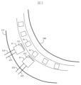
- FIG. 3 is a top view showing the positional relationship between the reaction vessels and the piezoelectric elements in the thermostatic chamber of the automatic analyzer according to the first embodiment.
- a plurality of reaction vessels including a first reaction vessel 31 and a second reaction vessel 32 are arranged in a circumferential direction in the thermostatic chamber 117, and a reaction disk turntable 108 is provided on the inner diameter side. As the turntable 108 rotates, the reaction vessels to be stirred move sequentially in the circumferential direction.
- a first vibration plate 211 is provided on the inner diameter side of the first piezoelectric element 21.
- the first vibration plate 211 is adhered to the GND electrode (negative voltage side electrode) of the first piezoelectric element 21, is in contact with the constant temperature water in the thermostatic bath 117, and faces the first reaction vessel 31.
- the GND electrode is connected to the amplifier 2 via the GND electrode side terminal 213 and the GND side switch 112 described below.
- the split electrode (positive voltage electrode) of the first piezoelectric element 21 is connected to the amplifier 2 via the split electrode side terminal 212 and the split side switch 111 described below.
- the second piezoelectric element 22 is located adjacent to the first piezoelectric element 21 in the circumferential direction.
- a second vibration plate 221 is provided on the inner diameter side of the second piezoelectric element 22.
- the second vibration plate 221 is adhered to the GND electrode (negative voltage side electrode) of the second piezoelectric element 22, contacts the constant temperature water in the constant temperature bath 117, and faces the second reaction vessel 32.
- the GND electrode is connected to the amplifier 2 via the GND electrode side terminal 223 and the GND side switch 122 described below.
- the split electrode (positive voltage electrode) of the second piezoelectric element 22 is connected to the amplifier 2 via the split electrode side terminal 222 and the split side switch 121 described below.
- FIGS. 4A and 4B are diagrams showing the circuit configuration for driving the piezoelectric elements of an automatic analyzer according to a comparative example, with FIG. 4A showing the case where only the first piezoelectric element is driven, and FIG. 4B showing the case where only the second piezoelectric element is driven.
- a first relay switch 18 is provided between the first piezoelectric element 21 and the first amplifier 2a, and a second relay switch 19 is provided between the second piezoelectric element 22 and the second amplifier 2b.
- the first relay switch 18 has only a split side switch 151 that turns on/off the connection between the split electrode of the first piezoelectric element 21 and the first amplifier 2a.
- the second relay switch 19 has only a split side switch 161 that turns on/off the connection between the split electrode of the second piezoelectric element 22 and the second amplifier 2b.
- the control unit turns on the split side switch 151 of the first relay switch 18 and turns off the split side switch 161 of the second relay switch 19. Then, the first amplifier 2a applies a voltage to the split electrode of the first piezoelectric element 21, driving the first piezoelectric element 21. However, since the GND electrode of the first piezoelectric element 21 and the first vibration plate 211 that is bonded to the GND electrode and in contact with the constant temperature water are not insulated from the high driving voltage, the first vibration plate 211 has a potential.
- a leakage current flows from the first vibration plate 211 of the first piezoelectric element 21 to the second vibration plate 221 of the second piezoelectric element 22 through the constant temperature water.
- This leakage current flows through the second relay switch 19 to the frame GND terminal 41 of the second amplifier 2b. Because the frame GND terminal 41 is also connected to the first amplifier 2a, a feedback loop of the leaked current is formed. In other words, because a portion of the output current of the first amplifier 2a leaks and returns, it is not possible to supply all of the output current of the first amplifier 2a to the first piezoelectric element 21, and the strength of the ultrasonic waves decreases.
- the control unit turns on the split side switch 161 of the second relay switch 19 and turns off the split side switch 151 of the first relay switch 18.
- the second amplifier 2b applies a voltage to the split electrode of the second piezoelectric element 22, driving the second piezoelectric element 22.
- the GND electrode of the second piezoelectric element 22 and the second vibration plate 221 which is bonded to the GND electrode and in contact with the constant temperature water, are not insulated from the high driving voltage, the second vibration plate 221 has a potential.
- a leakage current flows from the second vibration plate 221 of the second piezoelectric element 22 to the first vibration plate 211 of the first piezoelectric element 21 through the constant temperature water.
- This leakage current flows through the first relay switch 18 to the frame GND terminal 41 of the first amplifier 2a. Because the frame GND terminal 41 is also connected to the second amplifier 2b, a feedback loop of the leaked current is formed. In other words, because a portion of the output current of the second amplifier 2b leaks and returns, it is not possible to supply all of the output current of the second amplifier 2b to the second piezoelectric element 22, and the strength of the ultrasonic waves decreases.
- a first amplifier 2a for driving the first piezoelectric element 21 and a second amplifier 2b for driving the second piezoelectric element 22 are provided separately. Therefore, component variations in the two amplifiers may cause differences in the characteristics of the ultrasonic waves, which may affect the analysis accuracy.
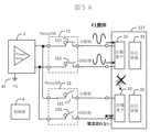
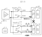
- Figures 5A and 5B are diagrams showing the circuit configuration for driving the piezoelectric elements of the automatic analyzer according to Example 1, where Figure 5A shows the case where only the first piezoelectric element is driven, and Figure 5B shows the case where only the second piezoelectric element is driven.
- Example 1 the first piezoelectric element 21 and the second piezoelectric element 22 are driven by a single common amplifier 2, so unlike the comparative example, the effects of component variations in the amplifier can be eliminated.
- a first relay switch 11 is provided between the first piezoelectric element 21 and the amplifier 2, and a second relay switch 12 is provided between the second piezoelectric element 22 and the amplifier 2.
- the first relay switch 11 has a split side switch 111 (positive voltage side switch) that turns ON/OFF the connection between the split electrode (positive voltage side electrode) of the first piezoelectric element 21 and the positive output electrode of the amplifier 2, and a GND side switch 112 (negative voltage side switch) that turns ON/OFF the connection between the GND electrode (negative voltage side electrode) of the first piezoelectric element and the negative output electrode of the amplifier 2.
- the second relay switch 12 has a split side switch 121 (positive voltage side switch) that turns on/off the connection between the split electrode (positive voltage side electrode) of the second piezoelectric element 22 and the positive output electrode of the amplifier 2, and a GND side switch 122 (negative voltage side switch) that turns on/off the connection between the GND electrode (negative voltage side electrode) of the second piezoelectric element and the negative output electrode of the amplifier 2.
- a split side switch 121 positive voltage side switch
- GND side switch 122 negative voltage side switch
- the control unit 4 turns ON the split side switch 111 and the GND side switch 112 of the first relay switch 11, and turns OFF the split side switch 121 and the GND side switch 122 of the second relay switch 12. Then, a voltage is applied to the split electrode of the first piezoelectric element 21 by the amplifier 2, driving the first piezoelectric element 21, and ultrasonic vibrations are transmitted into the first reaction vessel 31, stirring the sample and reagent.
- the GND electrode of the first piezoelectric element 21 and the first vibration plate 211 which is adhered to the GND electrode and in contact with the constant temperature water, are not insulated from the high driving voltage, so the first vibration plate 211 has a potential.
- the GND side switch 122 of the second relay switch 12 is OFF, there is no electrical continuity between the GND electrode attached to the second vibration plate 221 of the second piezoelectric element 22 and the negative output electrode of the amplifier 2, and no feedback loop through which leakage current flows is formed.
- all of the output current of the amplifier 2 can be supplied to the first piezoelectric element 21, making it possible to suppress a decrease in the strength of the ultrasonic waves.
- the control unit 4 turns ON the split side switch 121 and the GND side switch 122 of the second relay switch 12, and turns OFF the split side switch 111 and the GND side switch 112 of the first relay switch 11. Then, a voltage is applied to the split electrode of the second piezoelectric element 22 by the amplifier 2, driving the second piezoelectric element 22, and ultrasonic vibrations are transmitted into the second reaction vessel 32, stirring the sample and reagent.
- the GND electrode of the second piezoelectric element 22 and the second vibration plate 221, which is adhered to the GND electrode and in contact with the constant temperature water, are not insulated from the high driving voltage, so the second vibration plate 221 has a potential.
- the GND side switch 112 of the first relay switch 11 is OFF, there is no electrical continuity between the GND electrode attached to the first vibration plate 211 of the first piezoelectric element 21 and the negative output electrode of the amplifier 2, and no feedback loop through which leakage current flows is formed.
- all of the output current of the amplifier 2 can be supplied to the second piezoelectric element 22, making it possible to suppress a decrease in the strength of the ultrasonic waves.
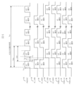
- Figure 6 is a time chart showing the operation when multiple piezoelectric elements are driven in the automatic analyzer of Example 1.
- the control unit 4 also outputs #1_DIVIDE (52), which is a signal to turn ON/OFF the split side switch 111 of the first relay switch 11, #1_GND (53), which is a signal to turn ON/OFF the GND side switch 112 of the first relay switch 11, #2_DIVIDE (54), which is a signal to turn ON/OFF the split side switch 121 of the second relay switch 12, and #2_GND (55), which is a signal to turn ON/OFF the GND side switch 122 of the second relay switch 12. Furthermore, the control unit 4 outputs the gain control POW_G2 (56), the gain control POW_G1 (57), and the gain control POW_G0 (58) as 3-bit gain control signals.
- the control unit 4 repeatedly turns the drive voltage on and off at a predetermined duty ratio until a certain agitation time Tstr (e.g., 2 sec) has elapsed.
- Tstr e.g. 2 sec
- Thd e.g., 2 msec
- the control unit 4 sets #2_Split (54) and #2_GND (55) to H in order to drive only the second piezoelectric element 22. Furthermore, when the setup time Tsu has elapsed, PWCNT (51) is set to H, causing the amplifier 2 to output a drive voltage, thereby driving the second piezoelectric element 22.
- the switch idle time Tid e.g., 4 msec
- #2_GND #2_GND
- Tbst is one period of the burst signal
- Ton is the ON time
- Toff is the OFF time
- the duty ratio is Ton/Tbst.
- Tbst is 50 msec
- Ton is 15 msec
- Toff is 35 msec. Note that Tbst, Ton, and Toff are the same times for the first piezoelectric element 21 and the second piezoelectric element 22.
- both the first piezoelectric element 21 and the second piezoelectric element 22 are driven in a time-division manner, within a fixed mixing time Tstr, mixing in the first reaction vessel 31 by the first piezoelectric element 21 and mixing in the second reaction vessel 32 by the second piezoelectric element 22 can be performed in parallel.
- n piezoelectric elements may also be driven in a time-division manner with a multiple number of m (n ⁇ m). In that case, by driving at least m of the n piezoelectric elements in a time-division manner with a duty ratio of less than 100/m%, it becomes possible to mix m reaction vessels within a fixed mixing time.
- Example 1 drives a total of two piezoelectric elements, the first piezoelectric element 21 and the second piezoelectric element 22, whereas Example 2 drives a total of four piezoelectric elements, the first piezoelectric element 21, the second piezoelectric element 22, the third piezoelectric element 23, and the fourth piezoelectric element.
- Example 2 drives a total of four piezoelectric elements, the first piezoelectric element 21, the second piezoelectric element 22, the third piezoelectric element 23, and the fourth piezoelectric element.
- the configuration for driving the first piezoelectric element 21 and the second piezoelectric element 22 is the same as in Example 1, and therefore the description will be omitted below as appropriate.
- FIG. 7 is a top view showing the positional relationship between the reaction vessels and the piezoelectric elements in the thermostatic chamber of the automatic analyzer of Example 2.
- a plurality of reaction vessels including a first reaction vessel 31, a second reaction vessel 32, a third reaction vessel 33, and a fourth reaction vessel 34 are arranged in a circumferential direction in the thermostatic chamber 117, and a turntable 108 of a reaction disk is provided on the inner diameter side.
- the turntable 108 rotates, the reaction vessels to be stirred move sequentially in the circumferential direction.
- the third piezoelectric element 23 is located adjacent to the second piezoelectric element 22 in the circumferential direction.
- a third vibration plate 231 is provided on the inner diameter side of the third piezoelectric element 23.
- the third vibration plate 231 is adhered to the GND electrode (negative voltage side electrode) of the third piezoelectric element 23, contacts the constant temperature water in the constant temperature bath 117, and faces the third reaction vessel 33.
- the GND electrode is connected to the amplifier 2 via the GND electrode side terminal 233 and a GND side switch 132 described below.
- the split electrode (positive voltage electrode) of the third piezoelectric element 23 is connected to the amplifier 2 via the split electrode side terminal 232 and a split side switch 131 described below.
- the fourth piezoelectric element 24 is located adjacent to the third piezoelectric element 23 in the circumferential direction.
- a fourth vibration plate 241 is provided on the inner diameter side of the fourth piezoelectric element 24.
- the fourth vibration plate 241 is adhered to the GND electrode (negative voltage side electrode) of the fourth piezoelectric element 24, contacts the constant temperature water in the constant temperature bath 117, and faces the fourth reaction vessel 34.
- the GND electrode is connected to the amplifier 2 via the GND electrode side terminal 243 and a GND side switch 142 described below.
- the split electrode (positive voltage electrode) of the fourth piezoelectric element 24 is connected to the amplifier 2 via the split electrode side terminal 242 and a split side switch 141 described below.
- Figures 8A to 8D are diagrams showing the circuit configuration for driving the piezoelectric elements of the automatic analyzer according to Example 2, with Figure 8A showing the case where only the first piezoelectric element is driven, Figure 8B showing the case where only the third piezoelectric element is driven, Figure 8C showing the case where only the second piezoelectric element is driven, and Figure 8D showing the case where only the fourth piezoelectric element is driven.
- a third relay switch 13 is provided between the third piezoelectric element 23 and the amplifier 2, and a fourth relay switch 14 is provided between the fourth piezoelectric element 24 and the amplifier 2.
- the third relay switch 13 has a split side switch 131 (positive voltage side switch) that turns ON/OFF the connection between the split electrode (positive voltage side electrode) of the third piezoelectric element 23 and the positive output electrode of the amplifier 2, and a GND side switch 132 (negative voltage side switch) that turns ON/OFF the connection between the GND electrode (negative voltage side electrode) of the third piezoelectric element and the negative output electrode of the amplifier 2.
- the fourth relay switch 14 has a split side switch 141 (positive voltage side switch) that turns on/off the connection between the split electrode (positive voltage side electrode) of the fourth piezoelectric element 24 and the positive output electrode of the amplifier 2, and a GND side switch 142 (negative voltage side switch) that turns on/off the connection between the GND electrode (negative voltage side electrode) of the fourth piezoelectric element and the negative output electrode of the amplifier 2.
- a split side switch 141 positive voltage side switch
- GND side switch 142 negative voltage side switch
- the control unit 4 turns ON the split side switch 111 and the GND side switch 112 of the first relay switch 11, and turns OFF the split side switch 121 and the GND side switch 122 of the second relay switch 12, the split side switch 131 and the GND side switch 132 of the third relay switch 13, and the split side switch 141 and the GND side switch 142 of the fourth relay switch 14. Then, the amplifier 2 applies a voltage to the split electrode of the first piezoelectric element 21, driving the first piezoelectric element 21, so that ultrasonic vibrations are transmitted into the first reaction vessel 31, and the sample and reagent are agitated.
- the GND side switch 122 of the second relay switch 12, the GND side switch 132 of the third relay switch 13, and the GND side switch 142 of the fourth relay switch 14 are OFF. Therefore, the GND electrodes of the second piezoelectric element 22, the third piezoelectric element 23, and the fourth piezoelectric element 24 are not electrically connected to the negative output electrode of the amplifier 2, and no feedback loop through which leakage current flows is formed. As a result, all of the output current of the amplifier 2 can be supplied to the first piezoelectric element 21, making it possible to suppress a decrease in the strength of the ultrasonic waves.
- the control unit 4 turns ON the split side switch 131 and the GND side switch 132 of the third relay switch 13, and turns OFF the split side switch 111 and the GND side switch 112 of the first relay switch 11, the split side switch 121 and the GND side switch 122 of the second relay switch 12, and the split side switch 141 and the GND side switch 142 of the fourth relay switch 14. Then, a voltage is applied to the split electrode of the third piezoelectric element 23 by the amplifier 2, and the third piezoelectric element 23 is driven, so that ultrasonic vibrations are transmitted into the third reaction vessel 33, and the sample and reagent are agitated.
- the GND side switch 112 of the first relay switch 11, the GND side switch 122 of the second relay switch 12, and the GND side switch 142 of the fourth relay switch 14 are OFF. Therefore, the GND electrodes of the first piezoelectric element 21, the second piezoelectric element 22, and the fourth piezoelectric element 24 are not electrically connected to the negative output electrode of the amplifier 2, and no feedback loop is formed through which leakage current flows. As a result, all of the output current of the amplifier 2 can be supplied to the third piezoelectric element 23, making it possible to suppress a decrease in the strength of the ultrasonic waves.
- the control unit 4 turns ON the split side switch 121 and the GND side switch 122 of the second relay switch 12, and turns OFF the split side switch 111 and the GND side switch 112 of the first relay switch 11, the split side switch 131 and the GND side switch 132 of the third relay switch 13, and the split side switch 141 and the GND side switch 142 of the fourth relay switch 14. Then, the amplifier 2 applies a voltage to the split electrode of the second piezoelectric element 22, driving the second piezoelectric element 22, so that ultrasonic vibrations are transmitted into the second reaction vessel 32, and the sample and reagent are agitated.
- the GND side switch 112 of the first relay switch 11, the GND side switch 132 of the third relay switch 13, and the GND side switch 142 of the fourth relay switch 14 are OFF. Therefore, the GND electrodes of the first piezoelectric element 21, the third piezoelectric element 23, and the fourth piezoelectric element 24 are not electrically connected to the negative output electrode of the amplifier 2, and no feedback loop through which leakage current flows is formed. As a result, all of the output current of the amplifier 2 can be supplied to the second piezoelectric element 22, making it possible to suppress a decrease in the strength of the ultrasonic waves.
- the control unit 4 turns ON the split side switch 141 and the GND side switch 142 of the fourth relay switch 14, and turns OFF the split side switch 111 and the GND side switch 112 of the first relay switch 11, the split side switch 121 and the GND side switch 122 of the second relay switch 12, and the split side switch 131 and the GND side switch 132 of the third relay switch 13. Then, the amplifier 2 applies a voltage to the split electrode of the fourth piezoelectric element 24, driving the fourth piezoelectric element 24, so that ultrasonic vibrations are transmitted into the fourth reaction vessel 34, and the sample and reagent are agitated.
- the GND side switch 112 of the first relay switch 11, the GND side switch 122 of the second relay switch 12, and the GND side switch 132 of the third relay switch 13 are OFF. Therefore, the GND electrodes of the first piezoelectric element 21, the second piezoelectric element 22, and the third piezoelectric element 23 are not electrically connected to the negative output electrode of the amplifier 2, and no feedback loop is formed through which leakage current flows. As a result, all of the output current of the amplifier 2 can be supplied to the fourth piezoelectric element 24, making it possible to suppress a decrease in the strength of the ultrasonic waves.
- FIG. 9 is a time chart showing the overall operation of stirring by each piezoelectric element.
- the first piezoelectric element 21 and the third piezoelectric element 23, which are arranged every other element are driven until the stirring time Tstr has elapsed, and after a certain pause time Tid2, the second piezoelectric element 22 and the fourth piezoelectric element 24, which are arranged every other element, are driven.
- the turntable rotates using a certain pause time Tid3, and the four reaction vessels to be the next targets of stirring are moved to positions facing each piezoelectric element.
- FIG. 10 is a time chart showing the operation of the automatic analyzer according to Example 2 when the first piezoelectric element and the third piezoelectric element are driven within a certain mixing time.
- control unit 4 in the second embodiment also outputs #3_DIVIDE (61), which is a signal that turns ON/OFF the split side switch 131 of the third relay switch 13, #3_GND (62), which is a signal that turns ON/OFF the GND side switch 132 of the third relay switch 13, #4_DIVIDE (63), which is a signal that turns ON/OFF the split side switch 141 of the fourth relay switch 14, and #4_GND (64), which is a signal that turns ON/OFF the GND side switch 142 of the fourth relay switch 14.
- the control unit 4 sets #3_division (61) and #3_GND (62) to H in order to drive only the third piezoelectric element 23. Furthermore, when the setup time Tsu has elapsed, PWCNT (51) is set to H, causing the amplifier 2 to output a drive voltage and drive the third piezoelectric element 23.
- the first piezoelectric element 21 is driven again, and the same operation is repeated until the mixing time Tstr is reached.
- the mixing in the first reaction vessel 31 by the first piezoelectric element 21 and the mixing in the third reaction vessel 33 by the third piezoelectric element 23 can be performed in parallel within a certain mixing time Tstr.
- FIG. 11 is a time chart showing the operation of the automatic analyzer according to the second embodiment when the second piezoelectric element and the fourth piezoelectric element are driven within a certain mixing time.
- the control unit 4 sets #4_division (63) and #4_GND (64) to H in order to drive only the fourth piezoelectric element 24. Furthermore, when the setup time Tsu has elapsed, PWCNT (51) is set to H, causing the amplifier 2 to output a drive voltage and drive the fourth piezoelectric element 24.
- the second piezoelectric element 22 is driven again, and the same operation is repeated until the mixing time Tstr is reached.
- the mixing in the second reaction vessel 32 by the second piezoelectric element 22 and the mixing in the fourth reaction vessel 34 by the fourth piezoelectric element 24 can be performed in parallel within a certain mixing time Tstr.
- FIG. 12 is a diagram showing a circuit configuration for driving the piezoelectric element of the automatic analyzer according to Example 3 (when only the first piezoelectric element is driven).
- Example 3 uses a differential output amplifier 2d as the amplifier, and drives the piezoelectric element by a differential output signal.
- the differential output amplifier 2d is suitable for driving piezoelectric elements.
- the differential output amplifier 2d is equipped with an analog GND terminal 42, but similar to the first embodiment, if the GND side switch 122 of the second relay switch 12 is turned OFF when the first piezoelectric element 21 is driven, no current feedback to the analog GND terminal 42 occurs. In addition, no current feedback to the frame GND terminal 41 occurs. As a result, it is possible to suppress a decrease in the strength of the ultrasonic waves.
- FIG. 13 is a diagram showing a circuit configuration for driving the piezoelectric element of the automatic analyzer according to Example 4 (when only the first piezoelectric element is driven).
- Example 4 uses a single-ended output amplifier 2s as the amplifier, and drives the piezoelectric element with a single-ended output signal.
- the single-ended output amplifier 2s also has an analog GND terminal 42, but similar to the first embodiment, if the GND side switch 122 of the second relay switch 12 is turned OFF when the first piezoelectric element 21 is driven, no current feedback occurs to the analog GND terminal 42. In addition, no current feedback occurs to the frame GND terminal 41. As a result, it is possible to suppress a decrease in the strength of the ultrasonic waves.
- the present invention is not limited to the above-described embodiments, but includes various modified examples.
- the above-described embodiments have been described in detail to clearly explain the present invention, and are not necessarily limited to those having all of the configurations described. It is possible to replace part of the configuration of one embodiment with the configuration of another embodiment, and it is also possible to add the configuration of another embodiment to the configuration of one embodiment. It is possible to add, delete, or replace part of the configuration of each embodiment with other configurations.
Landscapes
- Chemical & Material Sciences (AREA)
- Biochemistry (AREA)
- Physics & Mathematics (AREA)
- Health & Medical Sciences (AREA)
- Life Sciences & Earth Sciences (AREA)
- Analytical Chemistry (AREA)
- General Health & Medical Sciences (AREA)
- General Physics & Mathematics (AREA)
- Immunology (AREA)
- Pathology (AREA)
- Chemical Kinetics & Catalysis (AREA)
- Engineering & Computer Science (AREA)
- Mechanical Engineering (AREA)
- Automatic Analysis And Handling Materials Therefor (AREA)
Abstract
Description
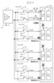
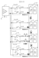
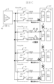
図9は、各圧電素子による攪拌の全体的な動作を示すタイムチャートである。本実施例では、4つ並んだ圧電素子のうち、第1圧電素子21と1つ飛びの第3圧電素子23を攪拌時間Tstrが経過するまで駆動し、一定の休止時間Tid2の後に、第2圧電素子22と1つ飛びの第4圧電素子24を駆動する。第1圧電素子21~第4圧電素子24による第1反応容器31~第4反応容器34の攪拌が終了すると、一定の休止時間Tid3を利用してターンテーブルが回転し、次の攪拌対象となる4つの反応容器が、各圧電素子の対面する位置に移動する。
Claims (11)
- 試料と試薬を攪拌するための超音波を発生させる圧電素子と、
前記圧電素子を駆動する増幅器と、
前記圧電素子と前記増幅器の間に設けられるリレースイッチと、
前記増幅器及び前記リレースイッチを制御する制御部と、を備えた自動分析装置において、
前記圧電素子は、第1圧電素子と、第2圧電素子と、を有し、
前記リレースイッチは、前記第1圧電素子と前記増幅器の間に設けられる第1リレースイッチと、前記第2圧電素子と前記増幅器の間に設けられる第2リレースイッチと、を有し、
前記第1リレースイッチは、前記第1圧電素子の正電圧側電極と前記増幅器との接続をON/OFFする正電圧側スイッチと、前記第1圧電素子のGND電極と前記増幅器との接続をON/OFFするGND側スイッチと、を有し、
前記第2リレースイッチは、前記第2圧電素子の正電圧側電極と前記増幅器との接続をON/OFFする正電圧側スイッチと、前記第2圧電素子のGND電極と前記増幅器との接続をON/OFFするGND側スイッチと、を有し、
前記第1圧電素子が駆動される場合、前記制御部は、前記第1リレースイッチにおける前記正電圧側スイッチ及び前記GND側スイッチをONし、前記第2リレースイッチにおける前記正電圧側スイッチ及び前記GND側スイッチをOFFし、
前記第2圧電素子が駆動される場合、前記制御部は、前記第2リレースイッチにおける前記正電圧側スイッチ及び前記GND側スイッチをONし、前記第1リレースイッチにおける前記正電圧側スイッチ及び前記GND側スイッチをOFFすることを特徴とする自動分析装置。 - 請求項1に記載の自動分析装置において、
前記第1圧電素子及び前記第2圧電素子が、共通の前記増幅器によって駆動されることを特徴とする自動分析装置。 - 請求項2に記載の自動分析装置において、
前記第1圧電素子及び前記第2圧電素子が、50%未満のデューティ比、かつ、時分割で所定時間駆動されることを特徴とする自動分析装置。 - 請求項2に記載の自動分析装置において、
前記圧電素子は、前記第1圧電素子及び前記第2圧電素子を含むn個の圧電素子を有し、前記n個のうち2個の圧電素子が、50%未満のデューティ比、かつ、時分割で所定時間駆動された後、
前記n個のうち他の2個の圧電素子が、50%未満のデューティ比、かつ、時分割で所定時間駆動されることを特徴とする自動分析装置。 - 請求項2に記載の自動分析装置において、
前記圧電素子は、前記第1圧電素子及び前記第2圧電素子を含むn個の圧電素子を有し、前記n個のうち少なくともm個の圧電素子が、100/m%未満のデューティ比、かつ、時分割で所定時間駆動されることを特徴とする自動分析装置。 - 請求項1又は2に記載の自動分析装置において、
前記増幅器は、差動出力信号により前記圧電素子を駆動することを特徴とする自動分析装置。 - 請求項1又は2に記載の自動分析装置において、
前記増幅器は、シングルエンド出力信号により前記圧電素子を駆動することを特徴とする自動分析装置。 - 試料と試薬を攪拌するための超音波を発生させる第1圧電素子及び第2圧電素子と、前記第1圧電素子及び前記第2圧電素子を駆動する増幅器と、前記増幅器を制御する制御部と、を備えた自動分析装置の制御方法であって、
前記増幅器が前記第1圧電素子を駆動する場合、前記制御部は、前記第1圧電素子の正電圧側電極及びGND電極を前記増幅器と導通させ、かつ、前記第2圧電素子の正電圧側電極及びGND電極を前記増幅器と導通させず、
前記増幅器が前記第2圧電素子を駆動する場合、前記制御部は、前記第2圧電素子の正電圧側電極及びGND電極を前記増幅器と導通させ、かつ、前記第1圧電素子の正電圧側電極及びGND電極を前記増幅器と導通させないことを特徴とする、自動分析装置の制御方法。 - 請求項8に記載の自動分析装置の制御方法において、
前記増幅器は、前記第1圧電素子及び前記第2圧電素子を、50%未満のデューティ比、かつ、時分割で所定時間駆動することを特徴とする、自動分析装置の制御方法。 - 請求項8に記載の自動分析装置の制御方法において、
前記自動分析装置は、前記第1圧電素子及び前記第2圧電素子を含むn個の圧電素子を備え、
前記増幅器は、前記n個のうち2個の圧電素子を、50%未満のデューティ比、かつ、時分割で所定時間駆動した後、
前記n個のうち他の2個の圧電素子を、50%未満のデューティ比、かつ、時分割で所定時間駆動することを特徴とする、自動分析装置の制御方法。 - 請求項8に記載の自動分析装置の制御方法において、
前記自動分析装置は、前記第1圧電素子及び前記第2圧電素子を含むn個の圧電素子を備え、
前記増幅器は、前記n個のうち少なくともm個の圧電素子を、100/m%未満のデューティ比、かつ、時分割で所定時間駆動することを特徴とする、自動分析装置の制御方法。
Priority Applications (4)
| Application Number | Priority Date | Filing Date | Title |
|---|---|---|---|
| US19/159,047 US20260219288A1 (en) | 2023-06-05 | 2024-03-26 | Automatic analyzer and control method thereof |
| JP2025525956A JPWO2024252761A1 (ja) | 2023-06-05 | 2024-03-26 | |
| CN202480010728.4A CN120712477A (zh) | 2023-06-05 | 2024-03-26 | 自动分析装置及其控制方法 |
| EP24819000.1A EP4722730A1 (en) | 2023-06-05 | 2024-03-26 | Automated analysis device and control method for same |
Applications Claiming Priority (2)
| Application Number | Priority Date | Filing Date | Title |
|---|---|---|---|
| JP2023-092432 | 2023-06-05 | ||
| JP2023092432 | 2023-06-05 |
Publications (1)
| Publication Number | Publication Date |
|---|---|
| WO2024252761A1 true WO2024252761A1 (ja) | 2024-12-12 |
Family
ID=93795766
Family Applications (1)
| Application Number | Title | Priority Date | Filing Date |
|---|---|---|---|
| PCT/JP2024/012129 Ceased WO2024252761A1 (ja) | 2023-06-05 | 2024-03-26 | 自動分析装置及びその制御方法 |
Country Status (5)
| Country | Link |
|---|---|
| US (1) | US20260219288A1 (ja) |
| EP (1) | EP4722730A1 (ja) |
| JP (1) | JPWO2024252761A1 (ja) |
| CN (1) | CN120712477A (ja) |
| WO (1) | WO2024252761A1 (ja) |
Citations (4)
| Publication number | Priority date | Publication date | Assignee | Title |
|---|---|---|---|---|
| JP2002204939A (ja) * | 2001-01-15 | 2002-07-23 | Hitachi Ltd | 撹拌装置及びその撹拌装置を備えた分析装置 |
| JP2007040847A (ja) * | 2005-08-03 | 2007-02-15 | Olympus Corp | 攪拌装置及び攪拌装置を備えた分析装置 |
| JP2021196329A (ja) | 2020-06-18 | 2021-12-27 | 株式会社日立ハイテク | 自動化学分析装置および電気インピーダンススペクトル測定器 |
| JP2022177414A (ja) * | 2021-05-18 | 2022-12-01 | 株式会社日立ハイテク | 自動化学分析装置、自動化学分析装置用メンテナンスキット、及び自動化学分析装置のメンテナンス方法 |
-
2024
- 2024-03-26 WO PCT/JP2024/012129 patent/WO2024252761A1/ja not_active Ceased
- 2024-03-26 US US19/159,047 patent/US20260219288A1/en active Pending
- 2024-03-26 EP EP24819000.1A patent/EP4722730A1/en active Pending
- 2024-03-26 JP JP2025525956A patent/JPWO2024252761A1/ja active Pending
- 2024-03-26 CN CN202480010728.4A patent/CN120712477A/zh active Pending
Patent Citations (4)
| Publication number | Priority date | Publication date | Assignee | Title |
|---|---|---|---|---|
| JP2002204939A (ja) * | 2001-01-15 | 2002-07-23 | Hitachi Ltd | 撹拌装置及びその撹拌装置を備えた分析装置 |
| JP2007040847A (ja) * | 2005-08-03 | 2007-02-15 | Olympus Corp | 攪拌装置及び攪拌装置を備えた分析装置 |
| JP2021196329A (ja) | 2020-06-18 | 2021-12-27 | 株式会社日立ハイテク | 自動化学分析装置および電気インピーダンススペクトル測定器 |
| JP2022177414A (ja) * | 2021-05-18 | 2022-12-01 | 株式会社日立ハイテク | 自動化学分析装置、自動化学分析装置用メンテナンスキット、及び自動化学分析装置のメンテナンス方法 |
Non-Patent Citations (1)
| Title |
|---|
| See also references of EP4722730A1 |
Also Published As
| Publication number | Publication date |
|---|---|
| US20260219288A1 (en) | 2026-07-30 |
| EP4722730A1 (en) | 2026-04-08 |
| CN120712477A (zh) | 2025-09-26 |
| JPWO2024252761A1 (ja) | 2024-12-12 |
Similar Documents
| Publication | Publication Date | Title |
|---|---|---|
| US20210270707A1 (en) | Chemical Analysis Device | |
| US8252231B2 (en) | Analyzer and its abnormality coping method | |
| WO2021256027A1 (ja) | 自動化学分析装置および電気インピーダンススペクトル測定器 | |
| US20100122586A1 (en) | Automatic analyzer and dispensing method | |
| US20240369588A1 (en) | Ultrasonic cleaner, automatic analyzer using same, and method for cleaning dispensing nozzle | |
| US8668875B2 (en) | Stirring device and an analyzing device | |
| US20090092518A1 (en) | Stirrer and analyzer | |
| JP7296865B2 (ja) | 化学分析装置 | |
| EP4722730A1 (en) | Automated analysis device and control method for same | |
| JP2010096638A (ja) | 自動分析装置 | |
| JP2001215232A (ja) | 化学分析装置 | |
| US20080240992A1 (en) | Stirrer,vessel, and analyzer | |
| JP2007040843A (ja) | 自動分析装置 | |
| JP7649873B2 (ja) | 自動分析装置及びその状態判定方法 | |
| JP7791768B2 (ja) | 自動分析装置 | |
| JP3832282B2 (ja) | 超音波攪拌装置及びそれを用いた自動分析装置 | |
| JP5219461B2 (ja) | 攪拌判定方法及び分析装置 | |
| JP2007108062A (ja) | 攪拌装置、容器及び分析装置 | |
| JP2009068879A (ja) | 分注装置、分注装置の分注ノズル洗浄方法及び自動分析装置 | |
| JP4406629B2 (ja) | 化学分析装置 | |
| JP2007057318A (ja) | 分析装置、供給装置、攪拌装置及び攪拌方法 | |
| EP4450975A1 (en) | Automated analyzing device | |
| JP3121829U (ja) | 自動分析装置 | |
| JP2025186686A (ja) | 自動分析装置及びその位置測定方法 | |
| CN116500286A (zh) | 一种具有超声波功能的全自动生化仪及应用方法 |
Legal Events
| Date | Code | Title | Description |
|---|---|---|---|
| 121 | Ep: the epo has been informed by wipo that ep was designated in this application |
Ref document number: 24819000 Country of ref document: EP Kind code of ref document: A1 |
|
| ENP | Entry into the national phase |
Ref document number: 2025525956 Country of ref document: JP Kind code of ref document: A |
|
| WWE | Wipo information: entry into national phase |
Ref document number: 2025525956 Country of ref document: JP |
|
| ENP | Entry into the national phase |
Ref document number: 2024819000 Country of ref document: EP Effective date: 20260105 |
|
| WWE | Wipo information: entry into national phase |
Ref document number: 2024819000 Country of ref document: EP |
|
| NENP | Non-entry into the national phase |
Ref country code: DE |
|
| ENP | Entry into the national phase |
Ref document number: 2024819000 Country of ref document: EP Effective date: 20260105 |
|
| ENP | Entry into the national phase |
Ref document number: 2024819000 Country of ref document: EP Effective date: 20260105 |
|
| ENP | Entry into the national phase |
Ref document number: 2024819000 Country of ref document: EP Effective date: 20260105 |
|
| ENP | Entry into the national phase |
Ref document number: 2024819000 Country of ref document: EP Effective date: 20260105 |
|
| ENP | Entry into the national phase |
Ref document number: 2024819000 Country of ref document: EP Effective date: 20260105 |