WO2024252758A1 - 異常検知装置、異常検知方法、及び異常検知プログラム - Google Patents
異常検知装置、異常検知方法、及び異常検知プログラム Download PDFInfo
- Publication number
- WO2024252758A1 WO2024252758A1 PCT/JP2024/011083 JP2024011083W WO2024252758A1 WO 2024252758 A1 WO2024252758 A1 WO 2024252758A1 JP 2024011083 W JP2024011083 W JP 2024011083W WO 2024252758 A1 WO2024252758 A1 WO 2024252758A1
- Authority
- WO
- WIPO (PCT)
- Prior art keywords
- period
- anomaly detection
- time
- virtual
- execution period
- Prior art date
- Legal status (The legal status is an assumption and is not a legal conclusion. Google has not performed a legal analysis and makes no representation as to the accuracy of the status listed.)
- Ceased
Links
Images





Classifications
-
- G—PHYSICS
- G06—COMPUTING OR CALCULATING; COUNTING
- G06F—ELECTRIC DIGITAL DATA PROCESSING
- G06F11/00—Error detection; Error correction; Monitoring
- G06F11/07—Responding to the occurrence of a fault, e.g. fault tolerance
Definitions
- This disclosure relates to an anomaly detection device, an anomaly detection method, and an anomaly detection program.
- This application claims priority to Japanese Application No. 2023-094215, filed on June 7, 2023, and incorporates by reference all of the contents of said Japanese application.
- Patent Document 1 discloses a system that detects abnormalities by monitoring the operation of applications in virtual machines (hereinafter also referred to as "VMs”) in a virtualization system virtualized by a hypervisor (hereinafter also referred to as "HV”), and by monitoring requests from VMs to HVs in the virtualization system.
- VMs virtual machines
- HV hypervisor
- An anomaly detection device is an anomaly detection device that detects an anomaly in one or more virtual systems included in a virtualization system configured on hardware, and includes a measurement unit that measures at least one of a first period, which is an execution period of the virtual system, and a second period, which is an execution period of a virtual machine executed in the virtual system, in a repetition of the first period and the second period, and an anomaly detection unit that detects an anomaly in the virtual system based on at least one of the first period and the second period measured by the measurement unit.
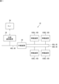
- FIG. 1 is a block diagram showing an example of the configuration of an in-vehicle system according to the first embodiment.
- FIG. 2 is a block diagram showing an example of the configuration of the in-vehicle device according to the first embodiment.
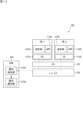
- FIG. 3 is a schematic diagram for explaining a virtual environment in the in-vehicle device according to the first embodiment.
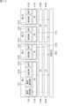
- FIG. 4 is a diagram illustrating an example of time management by a hypervisor.
- FIG. 5 is a diagram illustrating an example of measuring the execution period of a virtual machine.
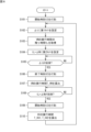
- FIG. 6 is a flowchart showing an example of a measurement process performed by a measurement program in the in-vehicle device according to the first embodiment.
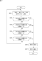
- FIG. 7 is a flowchart showing an example of an abnormality detection process by the abnormality detection program in the in-vehicle device according to the first embodiment.
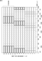
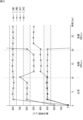
- FIG. 8 is a diagram showing the results of Simulation 1.
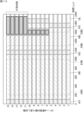
- FIG. 9 is a diagram showing the results of anomaly detection in Simulation 1.
- FIG. 10 is a diagram showing the results of Simulation 2.
- FIG. 11 is a diagram showing the results of anomaly detection in Simulation 2.
- FIG. 12 is a schematic diagram for explaining a virtual environment in an in-vehicle device according to the second embodiment.
- FIG. 13 is a schematic diagram for explaining a virtual environment in an in-vehicle device according to the third embodiment.
- FIG. 14 is a schematic diagram for explaining a virtual environment in an in-vehicle device according to the fourth embodiment.
- FIG. 15 is a schematic diagram for explaining a virtual environment in an in-vehicle device according to the fifth embodiment.
- FIG. 16 is a schematic diagram for explaining a virtual environment in an in-vehi
- Patent Document 1 ⁇ Problems to be Solved by the Present Disclosure>
- the system disclosed in Patent Document 1 can only detect predetermined types of abnormalities.
- the anomaly detection device is an anomaly detection device that detects an anomaly in one or more virtual systems included in a virtualization system configured on hardware, and includes a measurement unit that measures at least one of a first period, which is an execution period of the virtual system, and a second period, which is an execution period of a virtual machine executed in the virtual system, in a repetition of the first period and the second period, and an anomaly detection unit that detects an anomaly in the virtual system based on at least one of the first period and the second period measured by the measurement unit.
- an attack such as tampering
- unauthorized processing occurs in the virtual system
- the first period or the second period becomes abnormally long. Therefore, it is possible to detect an anomaly occurring in the virtual system, not limited to a specific type of anomaly, based on at least one of the first period and the second period.
- the measurement unit may measure the second period by recording the start time of the process by the virtual machine and the end time of the process by the virtual machine, and calculating the difference between the recorded end time and the start time.
- the second period can be measured by recording the start time and end time of the process by the virtual machine using timestamps.
- the measurement unit may measure the first period by calculating the difference between the recorded start time and end time. This makes it possible to measure the first period by recording the start time and end time of the process by the virtual machine using timestamps.
- the measurement unit may estimate a start timing of the second period by the virtual machine and record the start time by acquiring time information at the estimated start timing, and may estimate an end timing of the second period and record the end time by acquiring time information at the estimated end timing.
- a virtual machine cannot recognize the start and end of processing. For this reason, with the above configuration, for example, the virtual machine can record the start and end times of the virtual machine's processing.
- the measurement unit may estimate the end timing to be a timing a certain period of time after the start time is recorded. This allows the end timing of the virtual machine's processing to be estimated, for example, by the virtual machine itself.
- the certain period may be a period shorter than the remaining time of the second period from when the start time is recorded. If the end timing cannot be accurately estimated, for example, it is possible that a timing after the execution period of the virtual machine's processing ends may be mistakenly estimated as the end timing. With the above configuration, a timing before the execution period of the virtual machine's processing ends can be estimated as the end timing.
- the measurement unit may estimate the start timing of the second period of the next cycle based on the remaining time of the second period from when the start time was recorded and a margin period. This makes it possible to record the start time and end time of the second period over multiple cycles.
- the anomaly detection unit may detect the anomaly when the first period measured by the measurement unit deviates from a first normal range or when the second period measured by the measurement unit deviates from a second normal range. This makes it possible to detect anomalies occurring in the virtual system, not limited to specific types of anomalies.
- the anomaly detection unit may be included in the virtual machine. This makes it possible to detect an anomaly in the virtual system while suppressing the impact of the anomaly occurring in the virtual system.
- the anomaly detection unit may be implemented by a processor different from the processor that executes the virtual system. This makes it possible to accurately detect anomalies in the virtual system while suppressing the effects of anomalies that occur in the virtual system.
- the anomaly detection unit may be realized by a hardware security module. This allows anomalies to be detected by a hardware security module (HSM) that has security measures implemented.
- HSM hardware security module
- the anomaly detection unit may be included in a second virtual system that is a different virtual system from the first virtual system. This makes it possible to detect an anomaly in the first virtual system while suppressing the impact of an anomaly occurring in the first virtual system.
- the measurement unit may be included in the virtual machine. This makes it possible to measure the first period and the second period while suppressing the effects of an abnormality occurring in the virtual system.
- the measurement unit may be included in a first virtual machine that is the virtual machine, and the anomaly detection unit may be included in a second virtual machine that is executed in a second virtual system that is a virtual system different from the first virtual system that is the virtual system. This makes it possible to measure the first period and the second period while suppressing the effects of an anomaly occurring in the virtual system.
- the measurement unit may provide information indicating the first and second measured periods to the anomaly detection unit via a shared memory. This allows information on the measurement results by the measurement unit to be passed from the first virtual machine to the second virtual machine.
- the anomaly detection method is an anomaly detection method for detecting an anomaly in one or more virtual systems included in a virtualization system configured on hardware, and includes the steps of: measuring at least one of a first period, which is an execution period of the virtual system, and a second period, which is an execution period of a virtual machine executed in the virtual system, in a repetition of the first period and the second period; and detecting an anomaly in the virtual system based on the measured at least one of the first period and the second period. Therefore, it is possible to detect an anomaly that has occurred in the virtual system, not limited to a specific type of anomaly, based on at least one of the first period and the second period.
- the anomaly detection program is an anomaly detection program for detecting an anomaly in one or more virtual systems included in a virtualization system configured on hardware, and causes a computer to execute the steps of measuring at least one of a first period, which is an execution period of the virtual system, and a second period, which is an execution period of a virtual machine executed in the virtual system, in a repetition of the first period and the second period, and detecting an anomaly in the virtual system based on at least one of the first period and the second period measured. Therefore, it is possible to detect an anomaly that has occurred in the virtual system, not limited to a specific type of anomaly, based on at least one of the first period and the second period.
- the present disclosure can be realized not only as an anomaly detection device having the above-described characteristic configuration, an anomaly detection method having characteristic processing steps, and an anomaly detection program that causes a computer to execute the characteristic processing, but also as an anomaly detection system that includes the anomaly detection device, or as a semiconductor integrated circuit in which part or all of the anomaly detection device is implemented.
- In-vehicle system] 1 is a block diagram showing an example of the configuration of an in-vehicle system according to the first embodiment.
- the in-vehicle system 10 is mounted on a vehicle.
- the in-vehicle system 10 includes in-vehicle devices 100A, 100B, 100C, and 100D, a relay device 20, and an external communication device 30.
- the in-vehicle devices included in the in-vehicle system 10 are not limited to the in-vehicle devices 100A, 100B, 100C, and 100D, and in-vehicle devices not shown may also be included in the in-vehicle system 10.
- the in-vehicle system 10 is an in-vehicle network configured by the in-vehicle devices 100A, 100B, 100C, and 100D, the relay device 20, the external communication device 30, and communication cables (communication buses 40A, 40B, and 40C) connecting them.
- in-vehicle devices 100A, 100B, 100C, and 100D are arranged in various parts of the vehicle.
- the in-vehicle devices 100A, 100B, 100C, and 100D individually control the hardware of each part of the vehicle and monitor the status of the hardware of each part of the vehicle.
- the in-vehicle devices 100A, 100B, 100C, and 100D are ECUs (Electronic Control Units) for the control system, body system, and information system.
- the in-vehicle devices 100A, 100B, 100C, and 100D are collectively referred to as "in-vehicle devices 100.”
- the relay device 20 is connected to each of the in-vehicle devices 100A, 100B, 100C, and 100D via buses 40A, 40B, and 40C, such as a CAN (Controller Area Network) bus.
- buses 40A, 40B, and 40C such as a CAN (Controller Area Network) bus.
- the in-vehicle devices 100A and 100B are connected to the bus 40A.
- the in-vehicle devices 100C and 100D are connected to the bus 40B.
- the external communication device 30 is connected to the bus 40C.
- the relay device 20 relays communication between the buses 40A, 40B, and 40C.
- the relay device 20 and the in-vehicle device 100 use a specific communication protocol.
- the communication protocol is, for example, CAN, CAN FD (CAN with Flexible Data Rate), or Ethernet ("Ethernet” is a registered trademark).
- the relay device 20 functions as a gateway that relays communications between multiple in-vehicle devices 100.
- the in-vehicle devices 100 can transmit messages.
- the relay device 20 relays messages between the in-vehicle devices 100 connected to different buses.
- the relay device 20 can relay messages between the in-vehicle device 100A connected to the bus 40A and the in-vehicle device 100C connected to the bus 40B.
- the relay device 20 is connected to the external communication device 30 via the bus 40C.
- the external communication device 30 is, for example, a wireless communication terminal conforming to 5G or 4G, such as a TCU (Telematics Control Unit).
- the external communication device 30 can communicate with the server 50.
- the external communication device 30 and the relay device 20 relay communication between the server 50 and the in-vehicle device 100.
- the in-vehicle device 100 includes a processor 101, a non-volatile memory 102, a volatile memory 103, a communication interface (I/F) 104, and a hardware security module (HSM) 105.
- a processor 101 a non-volatile memory 102, a volatile memory 103, a communication interface (I/F) 104, and a hardware security module (HSM) 105.
- I/F communication interface
- HSM hardware security module
- the volatile memory 103 is, for example, a semiconductor memory such as SRAM (Static Random Access Memory) or DRAM (Dynamic Random Access Memory).
- the non-volatile memory 102 is, for example, a flash memory or a hard disk.
- the non-volatile memory 102 is capable of reading and writing data.
- Processor 101 is, for example, a CPU (Central Processing Unit). However, processor 101 is not limited to a CPU. Processor 101 may be a GPU (Graphics Processing Unit). Processor 101 is configured to be able to execute computer programs. However, processor 101 may include, for example, an ASIC (Application Specific Integrated Circuit) in part, or a programmable logic device such as an FPGA (Field Programmable Gate Array) in part.
- ASIC Application Specific Integrated Circuit
- FPGA Field Programmable Gate Array
- the processor 101 includes a clock (CLK) 106.
- the clock 106 outputs a clock signal at a constant cycle.
- the processor 101 includes, for example, a time stamp counter (TSC) (not shown) and can stamp the time of the processor 101.
- TSC time stamp counter
- the time stamped by the TSC is the internal time of the in-vehicle device 100.
- the internal time of the in-vehicle device 100 is, for example, an absolute time synchronized by an NTP (Network Time Protocol) server.
- the absolute time is, for example, Japan Standard Time (JST), and in another example, Coordinated Universal Time (UTC).
- JST Japan Standard Time
- UTC Coordinated Universal Time
- the internal time of the in-vehicle device 100 is also referred to as the "system time”.
- the communication I/F 104 is a communication interface that complies with the above-mentioned communication protocol for the in-vehicle network.
- the communication I/F 104 includes one communication port and is connected to one of the buses 40A, 40B, and 40C.
- the buses 40A, 40B, and 40B are collectively referred to as the "bus 40".
- the communication I/F 104 is connected to the in-vehicle device 100 and the relay device 20 via the bus 40.
- the in-vehicle device 100 can communicate with other in-vehicle devices 100, the relay device 20, and the external communication device 30 via the communication I/F 104.
- the in-vehicle device 100 can communicate with the server 50 via the external communication device 30 via the communication I/F 104.
- the non-volatile memory 102 has installed therein a hypervisor (HV) 110, operating systems (OS) 111A, 111B, and applications (APP) 112A, 112B.
- HV 110 is executed by the processor 101, and causes the in-vehicle device 100 to function as a virtual machine. Some or all of the HV 110, the OSs 111A, 111B, and the APPs 112A, 112B may be loaded into the volatile memory 103 and executed.
- FIG. 3 is a schematic diagram for explaining the virtualization system in the in-vehicle device according to the first embodiment.
- HV110 operates on hardware 120 (processor 101, non-volatile memory 102, volatile memory 103, communication I/F 104, etc.).
- HV110 can emulate virtual hardware (HW).
- HV110 is a virtual system that virtualizes hardware. By emulating one virtual HW, a virtual machine VM_1 is realized, and by emulating another virtual HW, a virtual machine VM_2 is realized.
- the "virtualization system” here refers to the entire computer system virtualized by HV110 in the in-vehicle device 100.
- OS111A runs on VM_1. In VM_1, APP112A runs on OS111A. OS111B runs on VM_2. In VM_2, APP112B runs on OS111B.
- APP112A is, for example, engine control software. When the processor 101 executes APP112A, the in-vehicle device 100 can control the engine.
- APP112B is, for example, power window control software. When the processor 101 executes APP112B, the in-vehicle device 100 can control the power window.
- HV110 manages the execution periods of VM_1 and VM_2.
- the execution periods of VM_1 and VM_2 are allocated in a time-sharing manner.
- a portion of the volatile memory 103 is used as shared memory 103a.
- the shared memory 103a is a memory area that can be used by VM_1 and VM_2.
- the non-volatile memory 102 stores the abnormality detection program 113 and the measurement program 114, which are computer programs.
- the non-volatile memory 102 stores, for example, data used in the abnormality detection program 113 and the measurement program 114.
- the abnormality detection program 113 and the measurement program 114 are installed in at least one in-vehicle device 100. That is, the abnormality detection program 113 and the measurement program 114 may be installed in all in-vehicle devices 100, or the abnormality detection program 113 and the measurement program 114 may be installed in only some of the in-vehicle devices 100.
- the abnormality detection program 113 and the measurement program 114 may be installed in the in-vehicle device 100 in which the HV 110 is installed. Either one or both of the abnormality detection program 113 and the measurement program 114 may be loaded into the volatile memory 103 and executed.
- the anomaly detection program 113 is a program for detecting anomalies in the HV 110.
- the HV 110 may be subject to attacks such as hyperjacking, hypercall attacks, hypervisor DoS (Denial of Services), VM escape attacks, and cross-VM cache (side channel attacks).
- the HV 110 may execute abnormal (illegal) processing or become unable to perform normal processing.
- the anomaly detection program 113 is a program for detecting such anomalies.
- the measurement program 114 is a program for acquiring data for detecting anomalies in the HV 110. Specifically, the measurement program 114 is a program for measuring the execution periods of VM_1 and VM_2.
- the in-vehicle device 100 is an example of an "anomaly detection device”.
- the in-vehicle device 100 has the functions of measurement units 121A and 121B, an abnormality detection unit 122, and an abnormality notification unit 123.
- the functions of the abnormality detection unit 122 and the abnormality notification unit 123 are realized by the processor 101 executing the abnormality detection program 113.
- the functions of the measurement units 121A and 121B are realized by the processor 101 executing the measurement program 114.
- FIG. 4 is a diagram for explaining an example of time management by a hypervisor.
- HV110 allocates the execution period of HV110, the execution period of VM_1, and the execution period of VM_2 in a time-division manner. Specifically, the time schedule of HV110 repeats a certain schedule period. Each schedule period includes the execution period of HV110, the execution period of VM_1, and the execution period of VM_2.
- C1 and C2 indicate schedule periods.
- Schedule period C1 starts at time t10, and the execution period of HV110 is first allocated from time t10 to t11.
- t11 to t12 is the execution period T1 of VM_1
- t12 to t13 is the execution period of HV110
- t13 to t14 is the execution period T2 of VM_2
- t14 to t15 is the execution period of HV110.
- t15 to t20 are idle periods.
- Schedule period C1 ends at time t20, and the next schedule period C2 starts.
- the measurement units 121A and 121B measure the execution period of HV110, the execution period T1 of VM_1, and the execution period T2 of VM_2.
- the measurement unit 121A measures the execution period T1 of VM_1.
- the measurement unit 121B measures the execution period T2 of VM_2.
- FIG. 5 is a diagram for explaining an example of measuring the execution period of VM_2.
- the measurement of the execution period T2 of VM_2 will be explained as a representative, but the measurement of the execution period T1 of VM_1 is similar.
- VM_2 can measure time using a timer based on the clock 106.
- This timer function of VM_2 is a function that measures time only within the execution period of VM_2 (hereinafter also referred to as "local time"), and cannot measure time during the execution period of the HV or the execution period of VM_1.
- VM_2 does not recognize each execution period as being a separate period, but rather recognizes them as a continuous period. In other words, VM_2 recognizes that the end of one execution period and the start of the next execution period are continuous. Therefore, the local time of VM_2 is the time between the end of one execution period and the start of the next execution period.
- VM_2 can recognize the start timing of VM_2's first execution period. However, as described above, VM_2 cannot recognize the end timing of VM_2's first execution period, or the start and end timings of the second and subsequent execution periods.
- VM_2 After VM_2 is started, VM_2 starts measurement unit 121B first. That is, measurement unit 121B starts before APP 112B. At the start timing of the first execution period of VM_2 (that is, the execution period immediately after VM_2 is started), more specifically, without delay from the time VM_2 is started, measurement unit 121B records the start time in an internal memory of in-vehicle device 100, for example, volatile memory 103.
- recording time information in internal memory is also referred to as "stamping".
- the measurement unit 121B estimates the timing when ⁇ t has elapsed from the start time of the execution period as the end time of the execution period.
- the measurement unit 121B sets the first timer of VM_2 to ⁇ t at the start time of the execution period.
- ⁇ t is a time corresponding to the length of one execution period, and more specifically, is a period that is a predetermined time shorter than one execution period.
- ⁇ t is a period shorter than the remaining time tL described below.
- the measurement unit 121B obtains the remaining time tL of the execution period.
- the measurement unit 121B estimates the timing ⁇ M after the actual end time of the execution period (i.e., the time after the remaining time tL has elapsed) as the start timing of the execution period of VM_2 in the next schedule cycle.
- the next execution period of VM_2 arrives after the execution period of HV110, the idle period, the execution period of HV110, the execution period of VM_1, and the execution period of HV110.
- VM_2 since VM_2 can only recognize the above-mentioned local time, VM_2 recognizes that the next execution period starts when tL has elapsed since the start time was stamped (although in reality, there is a slight error, so it may be slightly earlier or later). In other words, during the idle period, the execution period of HV110, and the execution period of VM_1, the timers of VM_2 (the first timer described above and the second timer described below) are stopped. Therefore, the time when the remaining time tL and ⁇ M have elapsed for VM_2 is the time when ⁇ M has elapsed since the start of the next execution period.
- the measurement unit 121B determines the timing when the remaining time tL has elapsed since the start time was stamped as the actual end time of the execution period.
- the measurement unit 121B sets the second timer of VM_2 to tL + ⁇ M, which is estimated as the start timing of the execution period of VM_2 in the next schedule cycle.
- the measurement unit 121B stamps the end time. In other words, the measurement unit 121B obtains time information at the end timing and records the obtained time information in the internal memory.
- the measurement unit 121B stamps the start time when the remaining time tL and ⁇ M have elapsed, that is, when the execution period of VM_2 in the next schedule cycle starts. That is, the measurement unit 121B records the start time by acquiring time information at the start time.
- ⁇ M is the margin time.
- the point when the remaining time tL has elapsed is the start timing for the next execution period, and the start time is stamped.
- ⁇ M is a value that avoids such stamping errors and ensures that the start time of the next execution period is stamped reliably.
- the measurement unit 121B estimates the timing ⁇ t after the start time as the end timing of the execution period, and stamps the end time when the end timing arrives. Thereafter, the start time and end time of each execution period are repeatedly stamped in the same manner as described above.
- the measurement unit 121B measures the execution period (second period) T_VM2 of VM_2 based on the timestamps of the start time and end time obtained as described above. Specifically, the measurement unit 121B measures the execution period T_VM2 of VM_2 by calculating the difference between the recorded end time and start time. Similarly, the measurement unit 121A measures the execution period T_VM1 of VM_1 by calculating the difference between the recorded end time and start time. The measurement of T_VM2 is performed during the execution period of VM_2. More specifically, the measurement of T_VM2 is performed repeatedly for each execution period of VM_2. The measurement of T_VM1 is performed during the execution period of VM_1. More specifically, the measurement of T_VM1 is performed repeatedly for each execution period of VM_1.
- the measurement units 121A and 121B can measure the execution period T_HV1 of HV110. For example, the measurement unit 121B writes the recorded start time and end time together with the measured execution period of VM_2 to the shared memory 103a. That is, the measurement unit 121B writes the execution period T_VM2 of VM_2 and the start time and end time of the execution period of VM_2 to the shared memory 103a for each execution period of VM_2. The measurement unit 121A reads the start time and end time of the execution period of VM_2 from the shared memory 103a.
- the measurement unit 121A reads the start time and end time of the execution period T_VM2 of VM_2 and the start time and end time of the execution period of VM_2 from the shared memory 103a for each execution period of VM_1.
- the measurement unit 121A can measure the execution period T_HV1 of the HV110 after the execution period of VM_1 in the schedule period C2 and before the execution period of VM_2 in the schedule period C2 by calculating the difference between the start time of the execution period of VM_2 in the schedule period C2 and the end time of the execution period of VM_1 in the schedule period C2.
- the measurement unit 121A can measure the execution period (and idle period) T_HV2 of the HV110 after the execution period of VM_2 in the schedule period C1 and before the execution period of VM_1 in the schedule period C2 by calculating the difference between the start time of the execution period of VM_1 in the schedule period C2 and the end time of the execution period of VM_2 in the schedule period C1.
- the anomaly detection unit 122 detects an anomaly in the HV 110 based on the execution periods T_HV1 and T_HV2 of the HV 110, the execution period T_VM1 of the VM_1, and the execution period T_VM2 of the VM_2 measured by the measurement units 121A and 121B. Detection of an anomaly in the HV 110 is repeatedly performed in synchronization with the schedule period.
- the abnormality detection unit 122 determines whether the execution period T_HV1 of the HV110 measured by the measurement units 121A and 121B deviates from the normal range R_HV1 (first normal range), and detects an abnormality in the HV110 if the execution period T_HV1 deviates from the normal range R_HV1.
- the abnormality detection unit 122 determines whether the execution period T_HV2 of the HV110 measured by the measurement units 121A and 121B deviates from the normal range R_HV2 (first normal range), and detects an abnormality in the HV110 if the execution period T_HV2 deviates from the normal range R_HV2.
- the abnormality detection unit 122 determines whether the execution period T_VM1 of VM_1 measured by the measurement unit 121A deviates from the normal range R_VM1 (second normal range), and detects an abnormality in the HV110 if the execution period T_VM1 deviates from the normal range R_VM1.
- the abnormality detection unit 122 determines whether the execution period T_VM2 of VM_2 measured by the measurement unit 121B deviates from the normal range R_VM2 (second normal range), and detects an abnormality in the HV110 if the execution period T_VM2 deviates from the normal range R_VM2.
- VM_1 and VM_2 are realized on HV110, but three or more virtual machines may be realized on HV110.
- measurement unit 121A operates on VM_1
- measurement unit 121B operates on VM_2
- measurement unit 121C operates on VM_3.
- Measurement unit 121B writes identification information of VM_2 together with the execution period, start time, and end time of VM_2 to shared memory 103a.
- Measurement unit 121C writes identification information of VM_3 together with the execution period, start time, and end time of VM_3 to shared memory 103a.
- the measurement unit 121A reads out the identification information of VM_2, the execution period, start time, and end time of VM_2, and the identification information of VM_3, the execution period, start time, and end time of VM_3 from the shared memory 103a.
- the measurement unit 121A specifies the execution period, start time, and end time of VM_2 and the execution period, start time, and end time of VM_3 from the identification information.
- the measurement unit 121A measures the execution period T_HV1 of the HV110 after the execution period of VM_1 and before the execution period of VM_2 by calculating the difference between the end time of the execution period of VM_1 and the start time of the execution period of VM_2 in one schedule period.
- the measurement unit 121A measures the execution period T_HV2 of the HV110 after the execution period of VM_2 and before the execution period of VM_3 by calculating the difference between the end time of the execution period of VM_2 and the start time of the execution period of VM_3 in one schedule cycle.
- the measurement unit 121A measures the execution period (and idle period) T_HV3 of the HV110 after the execution period of VM_3 in one schedule cycle and before the execution period of VM_1 in the next schedule cycle by calculating the difference between the end time of the execution period of VM_3 in one schedule cycle and the start time of the execution period of VM_1 in the next schedule cycle. Even if the number of virtual machines is four or more, the execution period of the HV110 can be measured in a similar manner.
- the abnormality notification unit 123 notifies the user of the detected abnormality.
- the abnormality notification unit 123 outputs notification data for notifying the detected abnormality. Specifically, the abnormality notification unit 123 generates a notification frame for notifying the detected abnormality and transmits the generated notification frame to the in-vehicle network.
- a user interface device (hereinafter also referred to as a "UI device") is connected to the in-vehicle system 10 (not shown).
- the UI device is one of the in-vehicle devices mounted on the vehicle.
- the UI device is used by the driver of the vehicle.
- the UI device includes an input device and a display device, and can accept input from the driver and display information to be provided to the driver.
- the UI device receives the notification frame transmitted from the in-vehicle device 100 and displays a screen for notifying the driver of the abnormality. This notifies the driver of the abnormality.
- a data storage device is connected to the in-vehicle system 10 (not shown).
- the data storage device is one of the in-vehicle devices mounted on the vehicle.
- the data storage device stores data related to anomalies detected by the anomaly detection unit 122 (hereinafter also referred to as "anomaly data").
- the data storage device receives a notification frame transmitted from the in-vehicle device 100 and stores the anomaly data. This stores a history of anomaly detection, and for example, a maintenance person performing maintenance on the vehicle can refer to the anomaly detection history.
- the external communication device 30 transmits a notification frame to a security department outside the vehicle.
- the security department is an organization that detects, analyzes, and advises on countermeasures against cyber attacks.
- the server 50 is used in the security department, and the notification frame is transmitted to the server 50. Based on the received notification frame, the server 50 notifies a terminal used by a security department staff member of the detected abnormality. This allows an appropriate response to be taken in response to the detected abnormality.
- FIG. 6 is a flowchart showing an example of measurement processing by a measurement program in the in-vehicle device according to the first embodiment.
- VM_1 and VM_2 are collectively referred to as "VM.”
- the processor 101 estimates that the time ⁇ M has elapsed since the start of the first execution period of the VM is the start timing.
- the processor 101 stamps the start time tS (step S101). This records the start time TS.
- the processor 101 sets the timer to ⁇ t (step S102).
- the processor 101 obtains the remaining time tL of the VM's execution period (step S103).
- the processor 101 sets tL+ ⁇ M in the timer (step S104).
- the processor 101 determines whether or not ⁇ t has arrived, i.e., whether or not the timer set for ⁇ t has expired (step S105). If ⁇ t has not arrived (NO in step S105), the processor 101 executes step S105 again.
- step S105 If ⁇ t has arrived (YES in step S105), the processor 101 stamps the end time TE (step S106). This records the end time TE.
- the processor 101 measures the execution period T_VM of the VM by calculating the difference TE-TS between the recorded start time TS and end time TE (step S107).
- the processor 101 writes the start time TS and end time TE together with the execution period T_VM to the shared memory 103a.
- the processor 101 determines whether tL+ ⁇ M has arrived, i.e., whether the timer set to tL+ ⁇ M has expired (step S108). If tL+ ⁇ M has not arrived (NO in step S108), the processor 101 executes step S108 again.
- step S108 the processor 101 estimates that the start timing has arrived and stamps the start time TS (step S109).
- the processor 101 writes the recorded start time TS to the shared memory 103a.
- the processor 101 calculates the execution periods T_HV1 and T_HV2 of the HV110 (step S110).
- T_HV1 is calculated as the difference between the end time of the execution period of VM_1 in the target schedule period and the start time of the execution period of VM_2 in the target schedule period.
- T_HV2 is calculated as the difference between the end time of the execution period of VM_2 in the schedule period immediately preceding the target schedule period and the start time of the execution period of VM_1 in the target schedule period.
- the execution period T_HV1 of the HV110 is calculated as the difference between the end time of the execution period of VM_1 in schedule period C2 and the start time of the execution period of VM_2 in schedule period C2.
- the execution period T_HV2 of HV110 is calculated as the difference between the end time of the execution period of VM_2 in schedule cycle C1 and the start time of the execution period of VM_1 in schedule cycle C2. Note that in step S110 in the first schedule cycle, since there is no previous schedule cycle, the calculation of the execution period T_HV2 of HV110 is omitted. Step S110 is omitted in the measurement process of VM_2.
- the processor 101 returns to step S102. This causes steps S102 to S110 to be repeated.
- FIG. 7 is a flowchart showing an example of an abnormality detection process performed by an abnormality detection program in an in-vehicle device according to the first embodiment.
- the processor 101 reads T_VM1, T_VM2, T_HV1, and T_HV2 from the shared memory 103a (step S201).
- the processor 101 determines whether T_VM1 deviates from the normal range R_VM1 (step S202).
- the processor 101 determines whether T_VM2 deviates from the normal range R_VM2 (step S203).
- the processor 101 determines whether T_HV1 deviates from the normal range R_HV1 (step S204).
- the processor 101 determines whether T_HV2 deviates from the normal range R_HV2 (step S205).
- step S205 the processor 101 returns to step S201.
- the loop of the abnormality detection process is controlled in synchronization with the schedule period.
- the processor 101 returns to step S201 when a timer with the same period as the schedule period expires.
- the processor 101 may return to step S201 by being called from the measurement program 114.
- the processor 101 detects an abnormality in the HV110 (step S206).
- the processor 101 notifies the driver of the detected abnormality (step S207). That is, for example, the processor 101 notifies the driver of the abnormality, stores the abnormality data in a data storage device, or notifies the security department of the abnormality. This completes the abnormality detection process.
- FIG. 7 shows an anomaly detection process in which two virtual machines, VM_1 and VM_2, are implemented on HV110, but the number of virtual machines is not limited to two and may be one or three or more.
- the execution period of HV110 between the execution periods of each virtual machine is measured as described above.
- the processor 101 compares the execution period of each virtual machine with the normal range, and compares each execution period of HV110 with the normal range. If at least one of the execution periods of all the virtual machines and all the execution periods of HV110 deviates from the normal range, an anomaly is detected.
- VM1 and VM2 may not include OS111A and 111B.
- the abnormality detection unit 122, the abnormality notification unit 123, the measurement unit 121A, and APP112A are executed as application programs on OS111A
- the measurement unit 121B and APP112B are executed as application programs on OS111B.
- the abnormality detection unit 122, the abnormality notification unit 123, and the measurement unit 121A are each realized as a function (interrupt processing routine) in APP112A
- the measurement unit 121B is realized as a function (interrupt processing routine) in APP112B.
- each of the anomaly detection unit 122, the anomaly notification unit 123, and the measurement unit 121A realizes its function through an interrupt (signal) generated by VM1, and the measurement unit 121B realizes its function through an interrupt generated by VM2. Therefore, in such a configuration, after starting up VM_2, VM_2 first needs to send a signal to APP112B to start up the measurement unit 121B. Similarly, after starting up VM_1, VM_1 first needs to send a signal to APP112A to start up the measurement unit 121A.
- VM_1 sends a signal to APP112A to start the measurement unit 121A, then VM1 sends a signal to APP112A to start the abnormality detection unit 122, and then VM1 sends a signal to APP112A to start the abnormality notification unit 123.
- the start time of execution period VM1 of VM_1 is stamped 100 ⁇ s after the actual start of VM1, and the end time of VM1 is stamped 900 ⁇ s after the actual start of VM1 (i.e., 100 ⁇ s before the actual end of VM1).
- the start time of execution period VM2 of VM_2 is stamped 100 ⁇ s after the actual start of VM2, and the end time of VM2 is stamped 400 ⁇ s after the actual start of VM2 (i.e., 100 ⁇ s before the actual end of VM2).
- Figure 8 shows the results of Simulation 1.
- the execution periods HV1, HV2, and HV3 of HV110 extended by the attack are shown in bold lines.
- the timing SVM1 of the start time and the timing EVM1 of the end time of VM1, as well as the timing SVM2 of the start time and the timing EVM2 of the end time of VM2 are shown in dashed lines.
- Simulation 1 the simulation was performed assuming that, in the 15 schedule periods, HV1, HV2, and HV3 from the 6th to 10th periods were each changed from 100 ⁇ s to 200 ⁇ s (i.e., extended by 100 ⁇ s), and HV1, HV2, and HV3 from the 11th to 15th periods were each changed from 100 ⁇ s to 300 ⁇ s (i.e., extended by 200 ⁇ s).
- HV1, HV2, and HV3 are each extended by 100 ⁇ s, so the idle period IDL disappears and the schedule cycle ends midway through HV3.
- HV1, HV2, and HV3 are each extended by 200 ⁇ s, so the idle periods IDL and HV3 disappear and the schedule cycle ends in the middle of VM2. As a result, the end time of VM2 fails to be stamped.
- the period from the punch timing SVM1 of the start time of VM1 to the punch timing EVM1 of the end time is measured as the execution period T_VM1 of VM_1.
- the period from the punch timing SVM2 of the start time of VM2 to the punch timing EVM2 of the end time is measured as the execution period T_VM2 of VM_2.
- the period from the punch timing EVM1 of the end time of VM1 to the punch timing SVM2 of the start time of VM2 is measured as the execution period T_HV1 of HV110.
- the period from the punch timing EVM2 of the end time of VM2 to the punch timing SVM1 of the start time of VM1 in the next schedule cycle is measured as the execution period T_HV2 of HV110.
- Figure 9 shows the results of anomaly detection in Simulation 1.
- the normal range R_HV1 was set to 250 ⁇ s or more and 350 ⁇ s or less.
- the normal range R_HV2 was set to 550 ⁇ s or more and 650 ⁇ s or less.
- the normal range R_VM1 was set to 750 ⁇ s or more and 850 ⁇ s or less.
- the normal range R_VM2 was set to 250 ⁇ s or more and 350 ⁇ s or less.
- the normal ranges R_HV1, R_HV2, R_VM1, and R_VM2 are shown as hatched areas. Note that the normal ranges R_HV1 and R_VM2 overlap and are shown as a single area.
- T_VM1, T_VM2, T_HV1, and T_HV2 are all within the normal range.
- T_VM1 is within the normal range R_VM1 throughout the simulation.
- T_HV2 10 ms after the start of the simulation, i.e., in the 5th cycle, T_HV2 is larger than the upper limit of the normal range R_HV2. Furthermore, from 12 ms to 18 ms (the 6th to 9th cycles), T_HV2 is smaller than the lower limit of the normal range R_HV2. After 20 ms (from the 11th cycle onwards), T_HV2 significantly exceeds the upper limit of the normal range R_HV2. This is caused by a failure to stamp in the end time of VM2.
- T_HV1 is within the normal range R_HV1.
- T_HV1 is greater than the upper limit of the normal range R_HV1.
- T_VM2 is within the normal range R_VM2. After 20 ms, i.e., from the eleventh cycle onwards, T_VM2 falls significantly below the lower limit of the normal range R_VM2. This is due to a failure to stamp in the end time of VM2.
- an abnormality in HV110 is detected after 10 ms, i.e., after the fifth cycle.
- FIG. 10 is a diagram showing the results of Simulation 2.
- Figure 11 shows the results of anomaly detection in Simulation 2.
- the normal ranges R_HV1, R_HV2, R_VM1, and R_VM2 are the same as in Simulation 1.
- T_VM1, T_VM2, T_HV1, and T_HV2 are all within the normal range.
- T_VM1 is within the normal range R_VM1 throughout the simulation.
- T_HV1 falls within the normal range R_HV1 throughout the simulation.
- T_HV2 is smaller than the lower limit of the normal range R_HV2. After 20 ms (cycles 11 and onward), T_HV2 significantly exceeds the upper limit of the normal range R_HV2. This is due to a failure to stamp the end time of VM2.
- T_VM2 is greater than the upper limit of the normal range R_VM2. After 20 ms (cycles 11 and onward), T_VM2 is significantly below the lower limit of the normal range R_VM2. This is due to a failure to stamp in the end time of VM2.
- FIG. 12 is a schematic diagram for explaining a virtual environment in an in-vehicle device according to the second embodiment.
- the HSM 105 has the functions of an anomaly detection unit 122A and an anomaly notification unit 123A.
- the VM_1 has only the function of the measurement unit 121A, and does not have the functions of the anomaly detection unit 122 or the anomaly notification unit 123.
- the measurement unit 121B of VM_2 outputs the measured T_VM2, and the output T_VM2 is input to the anomaly detection unit 122A of the HSM 105.
- the measurement unit 121A of VM_1 outputs the measured T_VM1, T_HV1, and T_HV2, and the output T_VM1, T_HV1, and T_HV2 are input to the anomaly detection unit 122A of the HSM 105.
- the abnormality detection unit 122A detects an abnormality in the HV110 based on the input T_VM1, T_VM2, T_HV1, and T_HV2.
- the functions of the abnormality detection unit 122A and the abnormality notification unit 123A are similar to the functions of the abnormality detection unit 122 and the abnormality notification unit 123 in the first embodiment, so a description thereof will be omitted.
- the anomaly detection unit 122A is provided in the HSM 105, the anomaly detection function is not affected by an anomaly in the HV 110, and anomalies can be detected accurately.
- FIG. 13 is a schematic diagram for explaining a virtual environment in an in-vehicle device according to the third embodiment.
- the VM_1 has only the function of the measurement unit 121A, and does not have the functions of the abnormality detection unit 122 and the abnormality notification unit 123.
- the in-vehicle device 100B has the functions of the abnormality detection unit 122B and the abnormality notification unit 123B.
- T_VM1, T_VM2, T_HV1, and T_HV2 output from the measurement units 121A and 121B of the in-vehicle device 100A are transmitted to the in-vehicle device 100B via the in-vehicle network.
- the in-vehicle device 100B receives T_VM1, T_VM2, T_HV1, and T_HV2, which are input to the abnormality detection unit 122B.
- the abnormality detection unit 122B detects an abnormality in the HV110 based on the input T_VM1, T_VM2, T_HV1, and T_HV2.
- the functions of the abnormality detection unit 122B and the abnormality notification unit 123B are similar to those of the abnormality detection unit 122 and the abnormality notification unit 123 in the first embodiment, and therefore will not be described.
- the abnormality detection unit 122B is realized by a processor (the processor 101 of the in-vehicle device 100B) different from the processor 101 of the in-vehicle device 100A that runs the HV 110. This makes it possible to accurately detect an abnormality in the HV 110 while suppressing the influence of an abnormality that occurs in the HV 110 on the in-vehicle device 100A.
- FIG. 14 is a schematic diagram for explaining a virtual environment in an in-vehicle device according to the fourth embodiment.
- the VM_1 has only the function of the measurement unit 121A, and does not have the functions of the abnormality detection unit 122 and the abnormality notification unit 123.
- the server 50 has the functions of the abnormality detection unit 501 and the abnormality notification unit 502.
- T_VM1, T_VM2, T_HV1, and T_HV2 output from the measurement units 121A and 121B of the in-vehicle device 100 are transmitted to the server 50 via the external communication device 30.
- the server 50 receives T_VM1, T_VM2, T_HV1, and T_HV2, which are input to the anomaly detection unit 501.
- the anomaly detection unit 501 detects an anomaly in the HV110 based on the input T_VM1, T_VM2, T_HV1, and T_HV2.
- the functions of the anomaly detection unit 501 and the anomaly notification unit 502 are similar to the functions of the anomaly detection unit 122 and the anomaly notification unit 123 in the first embodiment, and therefore a description thereof will be omitted.
- the abnormality detection unit 501 is realized by a processor (the processor of the server 50) different from the processor 101 of the in-vehicle device 100 that runs the HV 110. This makes it possible to accurately detect an abnormality in the HV 110 while suppressing the effect of an abnormality occurring in the HV 110 on the in-vehicle device 100.
- FIG. 15 is a schematic diagram for explaining a virtual environment in an in-vehicle device according to the fifth embodiment.
- the processor 101 of the in-vehicle device 100 is a multi-core processor including cores 101A and 101B.
- the processor 101 may have one clock, or each of the cores 101A and 101B may have a clock.
- Core 101A executes HV110A
- core 101B executes HV110B
- HV110A constitutes VM_1 and VM_2.
- HV110B constitutes VM_21 and VM_22.
- OS111A runs on VM_1.
- APP112A runs on OS111A.
- OS111B runs on VM_2.
- APP112B runs on OS111B.
- OS111C runs on VM_21. In VM_21, APP112C runs on OS111C. OS111D runs on VM_22. In VM_22, APP112D runs on OS111D.
- VM_1 has the functions of a measurement unit 121A, an abnormality detection unit 122, and an abnormality notification unit 123.
- VM_2 has the function of a measurement unit 121B.
- VM_21 has the function of a measurement unit 121C.
- VM_22 has the function of a measurement unit 121D.
- the functions of the measurement units 121A and 121B are the same as those of the measurement units 121A and 121B in the first embodiment. Even if each core 101A and 101B has a clock, the execution period of each virtual machine and the execution period of the HV do not depend on the time, so the measurement units 121A and 121B can measure the execution period of each virtual machine and the execution period of the HV.
- the measurement unit 121A measures the execution period T_VM1 of VM_1 and the execution periods T_HV1 and T_HV2 of HV110A.
- the measurement unit 121A writes the measured T_VM1, T_HV1, and T_HV2 to the shared memory 103a.
- the measurement unit 121B measures the execution period T_VM2 of VM_2.
- the measurement unit 121B writes the measured T_VM2 to the shared memory 103a.
- the measurement unit 121C measures the execution period of VM_21 (hereinafter referred to as "T_VM21”).
- the measurement unit 121C measures the execution period of HV110B (hereinafter referred to as "T_HV21” and “T_HV22").
- T_HV21 corresponds to T_HV1 in HV110A
- T_HV22 corresponds to T_HV2 in HV110A.
- the measurement unit 121C writes the measured values T_VM21, T_HV21, and T_HV22 to the shared memory 103a.
- the measurement unit 121D measures the execution period of VM_22 (hereinafter referred to as "T_VM22"). The measurement unit 121D writes the measured T_VM22 to the shared memory 103a.
- the abnormality detection unit 122 reads T_VM1, T_VM2, T_HV1, T_HV2, T_VM21, T_VM22, T_HV21, and T_HV22 from the shared memory 103a.
- the abnormality detection unit 122 determines whether T_HV21 deviates from the normal range (hereinafter referred to as "R_HV21"). If T_HV21 deviates from the normal range R_HV21, the abnormality detection unit 122 detects an abnormality in HV110B. The abnormality detection unit 122 determines whether T_HV22 deviates from the normal range (hereinafter referred to as "R_HV22"). If T_HV22 deviates from the normal range R_HV22, the abnormality detection unit 122 detects an abnormality in HV110B.
- the abnormality detection unit 122 determines whether VM_21 deviates from the normal range (hereinafter referred to as "R_VM21"). If the execution period T_VM21 deviates from the normal range R_VM21, the abnormality detection unit 122 detects an abnormality in HV110B. The abnormality detection unit 122 determines whether VM_22 deviates from the normal range (hereinafter referred to as "R_VM22"). If the execution period T_VM22 deviates from the normal range R_VM22, the abnormality detection unit 122 detects an abnormality in HV110B.
- the abnormality notification unit 123 If an abnormality is detected in HV110A, the abnormality notification unit 123 notifies the abnormality. If an abnormality is detected in HV110B, the abnormality notification unit 123 notifies the abnormality.
- an anomaly detection unit is included in HV110A, which is a virtual system different from HV110B, which is the virtual system targeted for anomaly detection. This makes it possible to accurately detect anomalies in HV110B while suppressing the effects of anomalies occurring in HV110B.
- FIG. 16 is a schematic diagram for explaining a virtual environment in an in-vehicle device according to the sixth embodiment.
- the HV 110 has the functions of the measurement unit 131, the abnormality detection unit 132, and the abnormality notification unit 133.
- the VM_1 does not have the functions of the measurement unit 121A, the abnormality detection unit 122, and the abnormality notification unit 123.
- the VM_2 does not have the function of the measurement unit 121B.
- the measurement unit 131 measures the execution period T_VM1 of VM_1, the execution period T_VM2 of VM_2, and the execution periods T_HV1 and T_HV2 of HV110.
- HV110 manages the execution periods of VM_1 and VM_2 and HV110. That is, HV110 measures the execution periods of VM_1, VM_2 and HV110 using a timer. HV110 calls VM_1 when the start time of VM_1 arrives, and switches to HV110's execution period when the end time of VM_1's execution period arrives. HV110 calls VM_2 when the start time of VM_2 arrives, and switches to HV110's execution period when the end time of VM_2's execution period arrives.
- the measurement unit 131 measures T_VM1, T_VM2, T_HV1, and T_HV2 using the execution period management function of the HV110. That is, the measurement unit 131 measures T_VM1, T_VM2, T_HV1, and T_HV2 without stamping the start time and end time of VM_1 and VM_2.
- the functions of the abnormality detection unit 132 and the abnormality notification unit 133 are similar to those of the abnormality detection unit 122 and the abnormality notification unit 123 in the first embodiment, so a description thereof will be omitted.
- the measurement unit 131 uses the functions of the HV 110, so there is no need to stamp the start times of VM_1 and VM_2, and the processing in the measurement unit 131 can be simplified.
Landscapes
- Engineering & Computer Science (AREA)
- Theoretical Computer Science (AREA)
- Quality & Reliability (AREA)
- Physics & Mathematics (AREA)
- General Engineering & Computer Science (AREA)
- General Physics & Mathematics (AREA)
- Debugging And Monitoring (AREA)
Abstract
異常検知装置は、ハードウェア上に構成された仮想化システムに含まれる1又は複数の仮想システムにおける異常を検知する異常検知装置であって、前記仮想システムの実行期間である第1期間と、前記仮想システムにおいて実行される仮想マシンの実行期間である第2期間との繰り返しにおいて、前記第1期間及び前記第2期間の少なくとも1つを測定する測定部と、前記測定部によって測定された前記第1期間及び前記第2期間の少なくとも1つに基づいて、前記仮想システムにおける異常を検知する異常検知部と、を備える。
Description
本開示は、異常検知装置、異常検知方法、及び異常検知プログラムに関する。本出願は、2023年6月7日出願の日本出願第2023-094215号に基づく優先権を主張し、前記日本出願に記載された全ての内容を援用するものである。
特許文献1には、ハイパーバイザ(以下、「HV」ともいう)によって仮想化された仮想化システムにおいて、仮想マシン(以下、「VM」ともいう)におけるアプリケーションの動作を監視したり、仮想化システムにおけるVMからHVへの要求を監視したりして、異常を検知するシステムが開示されている。
本開示の一態様に係る異常検知装置は、ハードウェア上に構成された仮想化システムに含まれる1又は複数の仮想システムにおける異常を検知する異常検知装置であって、前記仮想システムの実行期間である第1期間と、前記仮想システムにおいて実行される仮想マシンの実行期間である第2期間との繰り返しにおいて、前記第1期間及び前記第2期間の少なくとも1つを測定する測定部と、前記測定部によって測定された前記第1期間及び前記第2期間の少なくとも1つに基づいて、前記仮想システムにおける異常を検知する異常検知部と、を備える。
<本開示が解決しようとする課題>
しかしながら、特許文献1に開示されたシステムでは、予め定められた種類の異常しか検知することができない。
しかしながら、特許文献1に開示されたシステムでは、予め定められた種類の異常しか検知することができない。
<本開示の効果>
本開示によれば、特定の種類の異常に限らず、ハイパーバイザに生じた異常を検知することができる。
本開示によれば、特定の種類の異常に限らず、ハイパーバイザに生じた異常を検知することができる。
<本開示の実施形態の概要>
以下、本開示の実施形態の概要を列記して説明する。
以下、本開示の実施形態の概要を列記して説明する。
(1) 本実施形態に係る異常検知装置は、ハードウェア上に構成された仮想化システムに含まれる1又は複数の仮想システムにおける異常を検知する異常検知装置であって、前記仮想システムの実行期間である第1期間と、前記仮想システムにおいて実行される仮想マシンの実行期間である第2期間との繰り返しにおいて、前記第1期間及び前記第2期間の少なくとも1つを測定する測定部と、前記測定部によって測定された前記第1期間及び前記第2期間の少なくとも1つに基づいて、前記仮想システムにおける異常を検知する異常検知部と、を備える。仮想システムが改ざんされるなどの攻撃を受けた場合、仮想システムにおいて不正な処理が発生し、第1期間又は第2期間が異常に長くなる。したがって、第1期間及び第2期間の少なくとも1つに基づいて、特定の種類の異常に限らず、仮想システムに生じた異常を検知することができる。
(2) 上記(1)において、前記測定部は、前記仮想マシンによる処理の開始時刻と、前記仮想マシンによる処理の終了時刻とのそれぞれを記録し、記録された前記終了時刻と前記開始時刻との差分を算出することにより、前記第2期間を測定してもよい。タイムスタンプにより仮想マシンによる処理の開始時刻と終了時刻とのそれぞれを記録することで、第2期間を測定することができる。
(3) 上記(2)において、前記測定部は、記録された前記開始時刻と前記終了時刻との差分を算出することにより、前記第1期間を測定してもよい。これにより、タイムスタンプにより仮想マシンによる処理の開始時刻と終了時刻とのそれぞれを記録することで、第1期間を測定することができる。
(4) 上記(2)又は(3)において、前記測定部は、前記仮想マシンによる前記第2期間の開始タイミングを推定し、推定される前記開始タイミングにおける時刻情報を取得することによって前記開始時刻を記録し、前記第2期間の終了タイミングを推定し、推定される前記終了タイミングにおける時刻情報を取得することによって前記終了時刻を記録してもよい。仮想マシンは、処理の開始及び終了を認識することができない。このため、上記構成とすることにより、例えば仮想マシンによって、仮想マシンの処理の開始時刻及び終了時刻を記録することができる。
(5) 上記(4)において、前記測定部は、前記開始時刻を記録してから一定期間経過後のタイミングを前記終了タイミングとして推定してもよい。これにより、例えば仮想マシンによっても、仮想マシンの処理の終了タイミングを推定することができる。
(6) 上記(5)において、前記一定期間は、前記開始時刻を記録してからの前記第2期間の残り時間よりも短い期間であってもよい。終了タイミングを正確に推定できなければ、例えば、仮想マシンの処理の実行期間が終了した後のタイミングを終了タイミングと誤って推定してしまうことが考えられる。上記構成により、仮想マシンの処理の実行期間が終了するよりも前のタイミングを、終了タイミングとして推定することができる。
(7) 上記(4)から(6)のいずれか1つにおいて、前記測定部は、前記開始時刻を記録してからの前記第2期間の残り時間と、マージン期間とに基づいて、次の周期の第2期間の開始タイミングを推定してもよい。これにより、複数周期にわたって第2期間の開始時刻及び終了時刻を記録することができる。
(8) 上記(1)から(7)のいずれか1つにおいて、前記異常検知部は、前記測定部によって測定された前記第1期間が第1正常範囲を逸脱する場合、又は、前記第2期間が第2正常範囲を逸脱する場合に、前記異常を検知してもよい。これにより、特定の種類の異常に限らず、仮想システムに生じた異常を検知することができる。
(9) 上記(1)から(8)のいずれか1つにおいて、前記異常検知部は、前記仮想マシンに含まれてもよい。これにより、仮想システムに生じた異常による影響を抑制しつつ、仮想システムの異常を検出することができる。
(10) 上記(1)から(8)のいずれか1つにおいて、前記異常検知部は、前記仮想システムを実行するプロセッサとは異なるプロセッサによって実現されてもよい。これにより、仮想システムに生じた異常による影響を抑制しつつ、仮想システムの異常を正確に検知することができる。
(11) 上記(1)から(8)のいずれか1つにおいて、前記異常検知部は、ハードウェアセキュリティモジュールによって実現されてもよい。これにより、セキュリティ対策が施されたハードウェアセキュリティモジュール(HSM)によって異常を検知することができる。
(12) 上記(1)から(8)のいずれか1つにおいて、前記異常検知部は、前記仮想システムである第1仮想システムとは異なる仮想システムである第2仮想システムに含まれてもよい。これにより、第1仮想システムに生じた異常による影響を抑制しつつ、第1仮想システムの異常を検出することができる。
(13) 上記(1)から(12)のいずれか1つにおいて、前記測定部は、前記仮想マシンに含まれてもよい。これにより、仮想システムに生じた異常による影響を抑制しつつ、第1期間及び第2期間を測定することができる。
(14) 上記(1)から(8)のいずれか1つにおいて、前記測定部は、前記仮想マシンである第1仮想マシンに含まれ、前記異常検知部は、前記仮想システムである第1仮想システムとは異なる仮想システムである第2仮想システムにおいて実行される第2仮想マシンに含まれてもよい。これにより、仮想システムに生じた異常による影響を抑制しつつ、第1期間及び第2期間を測定することができる。
(15) 上記(14)において、前記測定部は、測定された前記第1期間及び前記第2期間を示す情報を、共有メモリを介して前記異常検知部へ与えてもよい。これにより、第1仮想マシンから第2仮想マシンへ、測定部による測定結果の情報を渡すことができる。
(16) 本実施形態に係る異常検知方法は、ハードウェア上に構成された仮想化システムに含まれる1又は複数の仮想システムにおける異常を検知する異常検知方法であって、前記仮想システムの実行期間である第1期間と、前記仮想システムにおいて実行される仮想マシンの実行期間である第2期間との繰り返しにおいて、前記第1期間及び前記第2期間の少なくとも1つを測定するステップと、測定された前記第1期間及び前記第2期間の少なくとも1つに基づいて、前記仮想システムにおける異常を検知するステップと、を含む。したがって、第1期間及び第2期間の少なくとも1つに基づいて、特定の種類の異常に限らず、仮想システムに生じた異常を検知することができる。
(17) 本実施形態に係る異常検知プログラムは、ハードウェア上に構成された仮想化システムに含まれる1又は複数の仮想システムにおける異常を検知するための異常検知プログラムであって、コンピュータに、前記仮想システムの実行期間である第1期間と、前記仮想システムにおいて実行される仮想マシンの実行期間である第2期間との繰り返しにおいて、前記第1期間及び前記第2期間の少なくとも1つを測定するステップと、測定された前記第1期間及び前記第2期間の少なくとも1つに基づいて、前記仮想システムにおける異常を検知するステップと、を実行させる。したがって、第1期間及び第2期間の少なくとも1つに基づいて、特定の種類の異常に限らず、仮想システムに生じた異常を検知することができる。
本開示は、上記のような特徴的な構成を備える異常検知装置、特徴的な処理をステップとする異常検知方法、及びコンピュータに特徴的な処理を実行させる異常検知プログラムとして実現することができるだけでなく、異常検知装置を備える異常検知システムとして実現したり、異常検知装置の一部又は全部を半導体集積回路として実現したりすることができる。
<本開示の実施形態の詳細>
以下、図面を参照しつつ、本発明の実施形態の詳細を説明する。なお、以下に記載する実施形態の少なくとも一部を任意に組み合わせてもよい。
以下、図面を参照しつつ、本発明の実施形態の詳細を説明する。なお、以下に記載する実施形態の少なくとも一部を任意に組み合わせてもよい。
[1.第1実施形態]
[1-1.車載システム]
図1は、第1実施形態に係る車載システムの構成の一例を示すブロック図である。車載システム10は、車両に搭載される。
[1-1.車載システム]
図1は、第1実施形態に係る車載システムの構成の一例を示すブロック図である。車載システム10は、車両に搭載される。
第1実施形態に係る車載システム10は、車載装置100A,100B,100C,100Dと、中継装置20と、外部通信装置30とを含む。なお、車載システム10に含まれる車載装置は、車載装置100A,100B,100C,100Dに限られず、図示しない車載装置が車載システム10に含まれてもよい。車載システム10は、車載装置100A,100B,100C,100D、中継装置20、外部通信装置30及びそれらを繋ぐ通信ケーブル(通信バス40A,40B,40C)によって構成される車載ネットワークである。
複数の車載装置100A,100B,100C,100Dは、車両の各部に配置される。車載装置100A,100B,100C,100Dは、車両の各部のハードウェアを個別に制御したり、車両の各部のハードウェアの状態を監視したりする。例えば、車載装置100A,100B,100C,100Dは、制御系、ボディ系、情報系のECU(Electronic Control Unit)である。なお、以下の説明では、車載装置100A,100B,100C,100Dを総称して「車載装置100」ともいう。
中継装置20は、車載装置100A,100B,100C,100DのそれぞれとCAN(Controller Area Network)バスのようなバス40A,40B,40Cを介して接続されている。具体的には、バス40Aには、車載装置100A,100Bが接続されている。バス40Bには、車載装置100C,100Dが接続されている。バス40Cには、外部通信装置30が接続されている。中継装置20は、バス40A,40B,40C間の通信を中継する。
中継装置20及び車載装置100は、特定の通信プロトコルを使用する。通信プロトコルは、例えば、CAN、CAN FD(CAN with Flexible Data Rate)、又はイーサネット(「Ethernet」は登録商標)である。
中継装置20は、複数の車載装置100間の通信を中継するゲートウェイとしての機能を有する。車載装置100は、メッセージを送信することができる。中継装置20は、異なるバスに接続された車載装置100間のメッセージを中継する。例えば、中継装置20は、バス40Aに接続された車載装置100Aと、バス40Bに接続された車載装置100Cとの間でメッセージを中継することができる。
中継装置20は、バス40Cを介して外部通信装置30に接続されている。外部通信装置30は、例えば5G又は4Gに準拠した無線通信端末であり、例えば、TCU(Telematics Control Unit)である。外部通信装置30は、サーバ50と通信することができる。外部通信装置30及び中継装置20は、サーバ50と車載装置100との間の通信を中継する。
[1-2.車載装置の構成]
図2は、第1実施形態に係る車載装置の構成の一例を示すブロック図である。車載装置100は、プロセッサ101と、不揮発性メモリ102と、揮発性メモリ103と、通信インタフェース(I/F)104と、ハードウェアセキュリティモジュール(HSM)105とを含む。
図2は、第1実施形態に係る車載装置の構成の一例を示すブロック図である。車載装置100は、プロセッサ101と、不揮発性メモリ102と、揮発性メモリ103と、通信インタフェース(I/F)104と、ハードウェアセキュリティモジュール(HSM)105とを含む。
揮発性メモリ103は、例えばSRAM(Static Random Access Memory)、DRAM(Dynamic Random Access Memory)等の半導体メモリである。不揮発性メモリ102は、例えばフラッシュメモリ、ハードディスク等である。不揮発性メモリ102は、データの読み出し及び書き込みが可能である。
プロセッサ101は、例えばCPU(Central Processing Unit)である。ただし、プロセッサ101は、CPUに限られない。プロセッサ101は、GPU(Graphics Processing Unit)であってもよい。プロセッサ101は、コンピュータプログラムを実行可能に構成される。ただしプロセッサ101は、例えば、ASIC(Application Specific Integrated Circuit)を一部に含んでもよいし、FPGA(Field Programmable Gate Array)等のプログラマブルロジックデバイスを一部に含んでもよい。
プロセッサ101は、クロック(CLK)106を含む。クロック106は、一定の周期でクロック信号を出力する。プロセッサ101は、例えば、図示しないタイムスタンプカウンタ(TSC)を含み、プロセッサ101の時間を打刻することができる。TSCによって打刻される時間は、車載装置100の内部時間である。車載装置100の内部時間は、例えば、NTP(Network Time Protocol)サーバによって同期された絶対時間である。絶対時間は、例えば、日本標準時(JST)であり、他の例では、協定世界時(UTC)である。以下、車載装置100の内部時間を「システム時間」ともいう。
通信I/F104は、上述した車載ネットワーク用の通信プロトコルに準拠した通信インタフェースである。通信I/F104は、1つの通信ポートを含み、バス40A,40B,40Cのいずれか1つに接続されている。以下、バス40A,40B,40Bを総称して「バス40」ともいう。通信I/F104は、バス40を介して車載装置100、及び中継装置20のそれぞれに接続されている。車載装置100は、通信I/F104によって、他の車載装置100、中継装置20、及び外部通信装置30と通信することができる。さらに、車載装置100は、通信I/F104によって、外部通信装置30を介してサーバ50と通信することができる。
不揮発性メモリ102には、ハイパーバイザ(HV)110、オペレーティングシステム(OS)111A,111B、アプリケーション(APP)112A,112Bがインストールされている。HV110は、プロセッサ101によって実行され、車載装置100を仮想マシンとして機能させる。HV110、OS111A,111B、及びAPP112A,112Bの一部又は全部は、揮発性メモリ103にロードされ、実行されてもよい。
図3は、第1実施形態に係る車載装置における仮想化システムを説明するための模式図である。HV110は、ハードウェア120(プロセッサ101、不揮発性メモリ102、揮発性メモリ103、及び通信I/F104等)上で動作する。HV110は、仮想ハードウェア(HW)をエミュレートすることができる。HV110は、ハードウェアを仮想化した仮想システムである。1つの仮想HWがエミュレートされることで、仮想マシンVM_1が実現され、別の1つの仮想HWがエミュレートされることで、仮想マシンVM_2が実現される。ここでいう「仮想化システム」は、車載装置100において、HV110によって仮想化されたコンピュータシステム全体を指す。仮想化システム200は、ハードウェア120上に構成され、HV110、VM_1、VM_1において実行されるOS111A及びAPP112A、VM_2、VM_2において実行されるOS111B及びAPP112Bを含む。第1実施形態では、仮想化システム200が1つのHV110を含む。しかし、これに限定されず、仮想化システム200は複数のHVを含んでもよい。なお、ここでは、1つのHVにおける仮想マシンの数を2つとしたが、これに限定されない。例えば、1つのHVにおける仮想マシンの数を1つとしてもよいし、3以上としてもよい。また、少なくとも1つの車載装置100がHVによる仮想化システムを有していればよい。すなわち、全ての車載装置100がHVによる仮想化システムを有していてもよく、一部の車載装置100のみがHVによる仮想化システムを有していてもよい。
OS111AはVM_1において動作する。VM_1において、APP112AはOS111A上で動作する。OS111BはVM_2において動作する。VM_2において、APP112BはOS111B上で動作する。APP112Aは、例えば、エンジンの制御ソフトウェアである。プロセッサ101がAPP112Aを実行することにより、車載装置100は、エンジンを制御することができる。APP112Bは、例えば、パワーウインドウの制御ソフトウェアである。プロセッサ101がAPP112Bを実行することにより、車載装置100は、パワーウインドウを制御することができる。
HV110は、VM_1及びVM_2の実行期間を管理する。VM_1の実行期間及びVM_2の実行期間は時分割で割り当てられる。
揮発性メモリ103の一部の領域は、共有メモリ103aとして用いられる。共有メモリ103aは、VM_1及びVM_2によって利用可能なメモリ領域である。
図2に戻り、不揮発性メモリ102には、コンピュータプログラムである異常検知プログラム113及び測定プログラム114が格納される。不揮発性メモリ102には、例えば、異常検知プログラム113及び測定プログラム114において使用されるデータが格納される。なお、少なくとも1つの車載装置100に異常検知プログラム113及び測定プログラム114がインストールされていればよい。すなわち、全ての車載装置100に異常検知プログラム113及び測定プログラム114がインストールされていてもよく、一部の車載装置100のみに異常検知プログラム113及び測定プログラム114がインストールされていてもよい。例えば、HV110がインストールされている車載装置100に、異常検知プログラム113及び測定プログラム114がインストールされていてもよい。異常検知プログラム113及び測定プログラム114のいずれか1つ又は両方は、揮発性メモリ103にロードされ、実行されてもよい。
異常検知プログラム113は、HV110の異常を検知するためのプログラムである。例えば、HV110は、ハイパージャック、ハイパーコール攻撃、ハイパーバイザDoS(Denial of Services)、VMエスケープ攻撃、クロスVMキャッシュ(サイドチャネル攻撃)等の攻撃を受けることがある。このような攻撃を受けたHV110は、異常(不正)な処理を実行したり、正常な処理が行えなくなったりする。異常検知プログラム113は、このような異常を検知するためのプログラムである。
測定プログラム114は、HV110の異常検知のためのデータを取得するためのプログラムである。具体的には、測定プログラム114は、VM_1,VM_2の実行期間を測定するためのプログラムである。
[1-3.車載装置の機能]
図3を参照し、車載装置100の機能を説明する。車載装置100は、「異常検知装置」の一例である。
図3を参照し、車載装置100の機能を説明する。車載装置100は、「異常検知装置」の一例である。
車載装置100は、測定部121A,121Bと、異常検知部122と、異常通知部123との機能を有する。プロセッサ101が異常検知プログラム113を実行することにより、異常検知部122及び異常通知部123の機能が実現される。プロセッサ101が測定プログラム114を実行することにより、測定部121A及び測定部121Bの機能が実現される。
異常検知プログラム113は、VM_1において実行されるプログラムである。VM_1において、異常検知プログラム113はOS111A上で動作する。すなわち、異常検知部122及び異常通知部123は、VM_1の機能である。
測定プログラム114は、VM_1及びVM_2において実行されるプログラムである。VM_1において、測定プログラム114はOS111A上で動作する。VM_2において、測定プログラム114はOS111B上で動作する。すなわち、測定部121Aは、VM_1の機能であり、測定部121Bは、VM_2の機能である。
図4は、ハイパーバイザによる時間管理の一例を説明するための図である。HV110によって、HV110の実行期間と、VM_1の実行期間と、VM_2の実行期間とが時分割で割り当てられる。具体的には、HV110のタイムスケジュールでは、一定のスケジュール周期が繰り返される。各スケジュール周期には、HV110の実行期間と、VM_1の実行期間と、VM_2の実行期間とが含まれる。
図4において、C1,C2はスケジュール周期を示す。スケジュール周期C1は、時刻t10において開始され、最初にHV110の実行期間が時刻t10~t11において割り当てられる。t11~t12はVM_1の実行期間T1であり、t12~t13はHV110の実行期間であり、t13~t14はVM_2の実行期間T2であり、t14~t15はHV110の実行期間である。t15~t20はアイドル期間である。時刻t20においてスケジュール周期C1が終了し、次のスケジュール周期C2が開始される。
図3に戻り、測定部121A,121Bは、HV110の実行期間と、VM_1の実行期間T1と、VM_2の実行期間T2とのそれぞれを測定する。
具体的な一例では、測定部121Aは、VM_1の実行期間T1を測定する。測定部121Bは、VM_2の実行期間T2を測定する。
図5は、VM_2の実行期間の測定の一例を説明するための図である。ここでは、代表してVM_2の実行期間T2の測定を説明するが、VM_1の実行期間T1の測定も同様である。
VM_2は、クロック106によるタイマを用いて時間を計測することができる。このVM_2のタイマ機能は、VM_2の実行期間内のみの時間(以下、「ローカル時間」ともいう)を計測する機能であり、HVの実行期間及びVM_1の実行期間における時間を計測することはできない。VM_2は、各実行期間は分割された期間であるとは認識せず、連続した期間として認識する。すなわち、VM_2は、1つの実行期間の終了と、次の実行期間の開始とが連続していると認識する。したがって、VM_2のローカル時間は、実行期間の終了と次の実行期間の開始とが連続した時間である。
VM_2は、VM_2の最初の実行期間の開始タイミングを認識することができる。しかし、上述したように、VM_2は、VM_2の最初の実行期間の終了タイミング、及び2回目以降の実行期間の開始タイミング及び終了タイミングを認識することができない。
VM_2の起動後、VM_2は測定部121Bを最初に起動する。すなわち、測定部121Bは、APP112Bよりも先に起動する。測定部121Bは、VM_2の最初の実行期間(つまり、VM_2が起動した直後の実行期間)の開始タイミングにおいて、さらに具体的には、VM_2が起動した時刻から遅滞なく、開始時刻を車載装置100の内部メモリ、例えば揮発性メモリ103に記録する。以下、時刻情報を内部メモリに記録することを「打刻」ともいう。
測定部121Bは、実行期間の開始時刻からΔt経過したタイミングを実行期間の終了タイミングとして推定する。測定部121Bは、実行期間の開始時刻において、VM_2の第1タイマをΔtにセットする。Δtは、1つの実行期間の長さに対応する時間であり、具体的には、1つの実行期間よりも所定時間短い期間である。Δtは、後述する残り時間tLより短い期間である。
測定部121Bは、実行期間の残り時間tLを取得する。測定部121Bは、実行期間の実際の終了時刻(つまり、残り時間tL経過後の時刻)よりΔM後のタイミングを、次のスケジュール周期におけるVM_2の実行期間の開始タイミングと推定する。VM_2の実行期間の後には、HV110の実行期間、アイドル期間、HV110の実行期間、VM_1の実行期間、及びHV110の実行期間を経た後、次のVM_2の実行期間が到来する。しかし、VM_2は上述したローカル時間しか認識できないため、開始時刻を打刻してからtLが経過した時点において(実際には微少な誤差があるため若干前後するが)、次の実行期間が開始されるようにVM_2は認識する。すなわち、アイドル期間、HV110の実行期間、及びVM_1の実行期間においては、VM_2のタイマ(上述した第1タイマ及び後述する第2タイマ)は停止する。したがって、VM_2にとって残り時間tL及びΔMが経過したタイミングは、次の実行期間が開始してからΔM経過したタイミングである。
測定部121Bは、開始時刻を打刻してから残り時間tL経過したタイミングを実行期間の実際の終了時刻として決定する。測定部121Bは、VM_2の第2タイマを、次のスケジュール周期におけるVM_2の実行期間の開始タイミングとして推定したtL+ΔMにセットする。
測定部121Bは、終了タイミングが到来すると、すなわち、第1タイマが満了すると、終了時刻を打刻する。言い換えれば、測定部121Bは、終了タイミングにおける時刻情報を取得し、取得した時刻情報を内部メモリに記録する。
測定部121Bは、残り時間tL及びΔMが経過したタイミング、すなわち、次のスケジュール周期におけるVM_2の実行期間の開始タイミングにおいて、開始時刻を打刻する。すなわち、測定部121Bは、開始タイミングにおける時刻情報を取得することによって開始時刻を記録する。
ΔMは、マージン時間である。ここで、残り時間tLが経過した時点を次の実行期間の開始タイミングとして開始時刻を打刻することを考える。この場合、タイマの精度によって時間の計測に揺らぎが生じた場合、前の実行期間が終了する前に、次の実行期間の開始時刻が打刻されることが考えられる。ΔMは、このような打刻の誤りを回避し、次の実行期間において開始時刻が確実に打刻されるための値である。
上述した最初の実行期間と同様にして、測定部121Bは、開始時刻からΔt経過後のタイミングを実行期間の終了タイミングとして推定し、終了タイミングが到来した場合に終了時刻を打刻する。以後、上述と同様にして、各実行期間の開始時刻及び終了時刻が繰り返し打刻される。
図3に戻り、測定部121Bは、上述のようにして得られた開始時刻及び終了時刻のタイムスタンプに基づいて、VM_2の実行期間(第2期間)T_VM2を測定する。具体的には、測定部121Bは、記録された終了時刻と開始時刻との差分を算出することにより、VM_2の実行期間T_VM2を測定する。同様にして、測定部121Aは、記録された終了時刻と開始時刻との差分を算出することにより、VM_1の実行期間T_VM1を測定する。T_VM2の測定は、VM_2の実行期間において行われる。さらに具体的には、T_VM2の測定は、VM_2の実行期間毎に繰り返し行われる。T_VM1の測定は、VM_1の実行期間において行われる。さらに具体的には、T_VM1の測定は、VM_1の実行期間毎に繰り返し行われる。
さらに測定部121A,121Bは、HV110の実行期間T_HV1を測定することができる。例えば、測定部121Bは、測定したVM_2の実行期間と共に、記録した開始時刻及び終了時刻を共有メモリ103aに書き込む。すなわち、測定部121Bは、VM_2の実行期間T_VM2及びVM_2の実行期間の開始時刻及び終了時刻を、VM_2の実行期間毎に共有メモリ103aに書き込む。測定部121Aは、VM_2の実行期間の開始時刻及び終了時刻を共有メモリ103aから読み出す。すなわち、測定部121Aは、VM_2の実行期間T_VM2及びVM_2の実行期間の開始時刻及び終了時刻を、VM_1の実行期間毎に共有メモリ103aから読み出す。ここで、スケジュール周期C1の次のスケジュール周期をC2とし、スケジュール周期C2が実行中であるとする。測定部121Aは、スケジュール周期C2におけるVM_2の実行期間の開始時刻とスケジュール周期C2におけるVM_1の実行期間の終了時刻との差分を算出することにより、スケジュール周期C2におけるVM_1の実行期間の後、且つ、スケジュール周期C2におけるVM_2の実行期間の前のHV110の実行期間T_HV1を測定することができる。測定部121Aは、スケジュール周期C2におけるVM_1の実行期間の開始時刻とスケジュール周期C1におけるVM_2の実行期間の終了時刻との差分を算出することにより、スケジュール周期C1におけるVM_2の実行期間の後、且つ、スケジュール周期C2におけるVM_1の実行期間の前のHV110の実行期間(及びアイドル期間)T_HV2を測定することができる。
異常検知部122は、測定部121A,121Bによって測定されたHV110の実行期間T_HV1,T_HV2、VM_1の実行期間T_VM1、及びVM_2の実行期間T_VM2に基づいて、HV110における異常を検知する。HV110における異常の検知は、スケジュール周期と同期して繰り返し行われる。
具体的には、異常検知部122は、測定部121A,121Bによって測定されたHV110の実行期間T_HV1が正常範囲R_HV1(第1正常範囲)を逸脱するか否かを判定し、実行期間T_HV1が正常範囲R_HV1を逸脱する場合に、HV110における異常を検知する。異常検知部122は、測定部121A,121Bによって測定されたHV110の実行期間T_HV2が正常範囲R_HV2(第1正常範囲)を逸脱するか否かを判定し、実行期間T_HV2が正常範囲R_HV2を逸脱する場合に、HV110における異常を検知する。
異常検知部122は、測定部121Aによって測定されたVM_1の実行期間T_VM1が正常範囲R_VM1(第2正常範囲)を逸脱するか否かを判定し、実行期間T_VM1が正常範囲R_VM1を逸脱する場合に、HV110における異常を検知する。異常検知部122は、測定部121Bによって測定されたVM_2の実行期間T_VM2が正常範囲R_VM2(第2正常範囲)を逸脱するか否かを判定し、実行期間T_VM2が正常範囲R_VM2を逸脱する場合に、HV110における異常を検知する。
上述した例では、VM_1及びVM_2の2つの仮想マシンがHV110上で実現されたが、HV110上で3以上の仮想マシンが実現されてもよい。VM_1,VM_2,VM_3の3つの仮想マシンがHV110上で実現される例を考える。この場合、例えば、VM_1上で測定部121Aが動作し、VM_2上で測定部121Bが動作し、VM_3上で測定部121Cが動作する。測定部121Bは、VM_2の実行期間と開始時刻及び終了時刻と共に、VM_2の識別情報を共有メモリ103aに書き込む。測定部121Cは、VM_3の実行期間と開始時刻及び終了時刻と共に、VM_3の識別情報を共有メモリ103aに書き込む。測定部121Aは、VM_2の識別情報、VM_2の実行期間、開始時刻及び終了時刻と、VM_3の識別情報、VM_3の実行期間、開始時刻及び終了時刻とを共有メモリ103aから読み出す。測定部121Aは、識別情報から、VM_2の実行期間、開始時刻及び終了時刻と、VM_3の実行期間、開始時刻及び終了時刻とを特定する。測定部121Aは、例えば、1つのスケジュール周期において、VM_1、VM_2、VM_3の順番でVM_1、VM_2、VM_3が実行される場合に、1つのスケジュール周期におけるVM_1の実行期間の終了時刻とVM_2の実行期間の開始時刻との差分を算出することにより、VM_1の実行期間の後、且つ、VM_2の実行期間の前のHV110の実行期間T_HV1を測定する。測定部121Aは、1つのスケジュール周期におけるVM_2の実行期間の終了時刻とVM_3の実行期間の開始時刻との差分を算出することにより、VM_2の実行期間の後、且つ、VM_3の実行期間の前のHV110の実行期間T_HV2を測定する。測定部121Aは、1つのスケジュール周期におけるVM_3の実行期間の終了時刻と、次のスケジュール周期におけるVM_1の実行期間の開始時刻との差分を算出することにより、1つのスケジュール周期におけるVM_3の実行期間の後、且つ、次のスケジュール周期におけるVM_1の実行期間の前のHV110の実行期間(及びアイドル期間)T_HV3を測定する。仮想マシンの数が4以上でも、同様にしてHV110の実行期間を測定することができる。
異常通知部123は、異常検知部122が異常を検知した場合に、検知された異常を通知する。
例えば、異常通知部123は、検知された異常を通知するための通知データを出力する。具体的には、異常通知部123は、検知された異常を通知するための通知フレームを生成し、生成した通知フレームを車載ネットワークに送信する。例えば、車載システム10には、ユーザインタフェース装置(以下、「UI装置」ともいう)が接続されている(図示せず)。UI装置は、車両に搭載された車載装置の1つである。UI装置は、車両のドライバによって使用される。UI装置は、入力装置及び表示装置を含み、ドライバからの入力を受け付け、ドライバへ提供する情報を表示することができる。UI装置は、車載装置100から送信された通知フレームを受信し、異常を通知するための画面を表示する。これにより、異常がドライバに通知される。
他の例では、車載システム10には、データ保存装置が接続されている(図示せず)。データ保存装置は、車両に搭載された車載装置の1つである。データ保存装置は、異常検知部122によって検知された異常に関するデータ(以下、「異常データ」ともいう)を保存する。データ保存装置は、車載装置100から送信された通知フレームを受信し、異常データを保存する。これにより、異常検知の履歴が保存され、例えば、車両の保守整備を行う保守者が、異常検知の履歴を参照することができる。
さらに他の例では、外部通信装置30が車外のセキュリティ部門へ通知フレームを送信する。セキュリティ部門は、サイバー攻撃の検出、分析、及び対応策のアドバイスを行う組織である。例えば、サーバ50はセキュリティ部門において用いられ、通知フレームはサーバ50へ送信される。サーバ50は、受信した通知フレームに基づいて、セキュリティ部門の担当者が使用する端末に、検知された異常を通知する。これにより、検知された異常に対して適切な対応がとられる。
[1-4.車載装置の動作]
以下、第1実施形態に係る車載装置の動作について説明する。
以下、第1実施形態に係る車載装置の動作について説明する。
図6は、第1実施形態に係る車載装置における測定プログラムによる測定処理の一例を示すフローチャートである。以下の説明では、VM_1,VM_2を総称して「VM」という。
VMが起動されると、最初の実行期間が開始される。プロセッサ101は、VMの最初の実行期間の開始からΔM経過を開始タイミングと推定する。プロセッサ101は、開始タイミングが到来すると、開始時刻tSを打刻する(ステップS101)。これにより、開始時刻TSが記録される。
プロセッサ101は、Δtにタイマを設定する(ステップS102)。
プロセッサ101は、VMの実行期間の残り時間tLを取得する(ステップS103)。プロセッサ101は、tL+ΔMをタイマに設定する(ステップS104)。
プロセッサ101は、Δtが到来したか否か、すなわち、Δtに設定されたタイマが満了したか否かを判定する(ステップS105)。Δtが到来していない場合(ステップS105においてNO)、プロセッサ101は、ステップS105を再度実行する。
Δtが到来した場合(ステップS105においてYES)、プロセッサ101は、終了時刻TEを打刻する(ステップS106)。これにより、終了時刻TEが記録される。
プロセッサ101は、記録された開始時刻TSと終了時刻TEとの差分TE-TSを算出することにより、VMの実行期間T_VMを測定する(ステップS107)。プロセッサ101は、実行期間T_VMと共に、開始時刻TS及び終了時刻TEを共有メモリ103aに書き込む。
プロセッサ101は、tL+ΔMが到来したか否か、すなわち、tL+ΔMに設定されたタイマが満了したか否かを判定する(ステップS108)。tL+ΔMが到来していない場合(ステップS108においてNO)、プロセッサ101は、ステップS108を再度実行する。
tL+ΔMが到来した場合(ステップS108においてYES)、プロセッサ101は、開始タイミングが到来したと推定し、開始時刻TSを打刻する(ステップS109)。プロセッサ101は、記録した開始時刻TSを共有メモリ103aに書き込む。
例えば、VM_1では、プロセッサ101がHV110の実行期間T_HV1,T_HV2を算出する(ステップS110)。T_HV1は、対象のスケジュール周期におけるVM_1の実行期間の終了時刻と、対象のスケジュール周期におけるVM_2の実行期間の開始時刻との差分として算出される。T_HV2は、対象のスケジュール周期の1つ前のスケジュール周期におけるVM_2の実行期間の終了時刻と、対象のスケジュール周期におけるVM_1の実行期間の開始時刻との差分として算出される。例えば、対象のスケジュール周期をC2とし、スケジュール周期C2の1つ前のスケジュール周期をC1とすると、スケジュール周期C2におけるVM_1の実行期間の終了時刻と、スケジュール周期C2におけるVM_2の実行期間の開始時刻との差分として、HV110の実行期間T_HV1が算出される。スケジュール周期C1におけるVM_2の実行期間の終了時刻と、スケジュール周期C2におけるVM_1の実行期間の開始時刻との差分として、HV110の実行期間T_HV2が算出される。なお、最初のスケジュール周期におけるステップS110においては、それ以前のスケジュール周期がないため、HV110の実行期間T_HV2の算出は省略される。ステップS110は、VM_2の測定処理では省略される。
プロセッサ101は、ステップS102に戻る。これにより、ステップS102~S110が繰り返される。
図7は、第1実施形態に係る車載装置における異常検知プログラムによる異常検知処理の一例を示すフローチャートである。
プロセッサ101は、T_VM1,T_VM2,T_HV1,T_HV2を共有メモリ103aから読み出す(ステップS201)。
プロセッサ101は、T_VM1が正常範囲R_VM1を逸脱するか否かを判定する(ステップS202)。
T_VM1が正常範囲R_VM1内である場合(ステップS202においてNO)、プロセッサ101は、T_VM2が正常範囲R_VM2を逸脱するか否かを判定する(ステップS203)。
T_VM2が正常範囲R_VM2内である場合(ステップS203においてNO)、プロセッサ101は、T_HV1が正常範囲R_HV1を逸脱するか否かを判定する(ステップS204)。
T_HV1が正常範囲R_HV1内である場合(ステップS204においてNO)、プロセッサ101は、T_HV2が正常範囲R_HV2を逸脱するか否かを判定する(ステップS205)。
T_HV2が正常範囲R_HV2内である場合(ステップS205においてNO)、プロセッサ101は、ステップS201に戻る。例えば、異常検知処理のループは、スケジュール周期と同期して制御される。具体的には、スケジュール周期と同じ周期のタイマが満了したときにプロセッサ101はステップS201に戻る。他の例として、測定プログラム114からの呼び出しによって、プロセッサ101はステップS201に戻ってもよい。
T_VM1,T_VM2,T_HV1,T_HV2のいずれか1つが正常範囲R_VM1,R_VM2,R_HV1,R_HV2を逸脱する場合(ステップS202,S203,S204,S205においてYES)、プロセッサ101は、HV110の異常を検知する(ステップS206)。
プロセッサ101は、検知された異常を通知する(ステップS207)。すなわち、例えば、プロセッサ101は、ドライバに異常を通知したり、データ保存装置に異常データを保存したり、セキュリティ部門に異常を通知したりする。以上で、異常検知処理が終了する。
なお、図7の例では、VM_1及びVM_2の2つの仮想マシンがHV110上で実現される場合の異常検知処理を示しているが、仮想マシンの数は2に限定されず、1つであってもよいし、3以上であってもよい。仮想マシンの数が3以上の場合は、上述したように各仮想マシンの実行期間の間におけるHV110の実行期間が測定される。異常検知処理では、プロセッサ101が各仮想マシンの実行期間を正常範囲と比較し、HV110の各実行期間を正常範囲と比較する。全ての仮想マシンの実行期間及びHV110の全ての実行期間のうちの少なくとも1つが正常範囲を逸脱する場合、異常が検知される。
変形例として、VM1,VM2がOS111A,111Bを含まなくてもよい。VM1,VM2がOS111A,111Bを含む場合、上述したように、異常検知部122、異常通知部123、測定部121A及びAPP112Aは、OS111A上のアプリケーションプログラムとして実行され、測定部121B及びAPP112Bは、OS111B上のアプリケーションプログラムとして実行される。一方、VM1,VM2がOS111A,111Bを含まない場合、異常検知部122、異常通知部123、及び測定部121Aのそれぞれは、APP112A内の関数(割り込み処理ルーチン)として実現され、測定部121Bは、APP112B内の関数(割り込み処理ルーチン)として実現される。
VM1,VM2がOS111A,111Bを含まない場合、異常検知部122、異常通知部123、及び測定部121Aのそれぞれは、VM1が発生した割り込み(シグナル)によって機能を実現し、測定部121Bは、VM2が発生した割り込みによって機能を実現する。したがって、このような構成においては、VM_2の起動後、VM_2は測定部121Bを起動するためのシグナルを最初にAPP112Bへ送ればよい。VM_1も同様に、VM_1の起動後、VM_1は測定部121Aを起動するためのシグナルを最初にAPP112Aへ送ればよい。さらに具体的には、VM_1の起動後、VM_1は測定部121Aを起動するためのシグナルをAPP112Aへ送り、次にVM1は異常検知部122を起動するためのシグナルをAPP112Aへ送り、次にVM1は異常通知部123を起動するためのシグナルをAPP112Aへ送る。
[1-5.異常検知のシミュレーション]
発明者は、第1実施形態に係る異常検知方法のシミュレーションを実施した。シミュレーションには、MATLAB(登録商標)が用いられた。
発明者は、第1実施形態に係る異常検知方法のシミュレーションを実施した。シミュレーションには、MATLAB(登録商標)が用いられた。
[1-4-1.シミュレーション1]
シミュレーションでは、1回のスケジュール周期において、1回目のHV110の実行期間HV1、VM_1の実行期間VM1、2回目のHV110の実行期間HV2、VM_2の実行期間VM2、3回目のHV110の実行期間HV3、及びアイドル期間IDLがこの順番で推移することとした。HV110の実行期間HV1,HV2,HV3のそれぞれを100μs、VM_1の実行期間VM1を1000μs、VM_2の実行期間VM2を500μs、アイドル期間IDLを200μsとし、スケジュール周期を2000μsとした。
シミュレーションでは、1回のスケジュール周期において、1回目のHV110の実行期間HV1、VM_1の実行期間VM1、2回目のHV110の実行期間HV2、VM_2の実行期間VM2、3回目のHV110の実行期間HV3、及びアイドル期間IDLがこの順番で推移することとした。HV110の実行期間HV1,HV2,HV3のそれぞれを100μs、VM_1の実行期間VM1を1000μs、VM_2の実行期間VM2を500μs、アイドル期間IDLを200μsとし、スケジュール周期を2000μsとした。
さらに、VM_1の実行期間VM1の開始時刻の打刻タイミングを、VM1の実際の開始から100μs後とし、VM1の終了時刻の打刻タイミングを、VM1の実際の開始から900μs後(すなわち、VM1の実際の終了から100μs前)とした。VM_2の実行期間VM2の開始時刻の打刻タイミングを、VM2の実際の開始から100μs後とし、VM2の終了時刻の打刻タイミングを、VM2の実際の開始から400μs後(すなわち、VM2の実際の終了から100μs前)とした。
図8は、シミュレーション1の結果を示す図である。図において、攻撃によって延長されたHV110の実行期間HV1,HV2,HV3を太線のグラフで示している。VM1の開始時刻の打刻タイミングSVM1及び終了時刻の打刻タイミングEVM1、並びに、VM2の開始時刻の打刻タイミングSVM2及び終了時刻の打刻タイミングEVM2のそれぞれを破線で示している。
シミュレーション1では、15回のスケジュール周期において、6周期目から10周期目のHV1,HV2,HV3のそれぞれが100μsから200μsへ変更され(すなわち、100μs延長され)、11周期目から15周期目のHV1,HV2,HV3のそれぞれが100μsから300μsへ変更された(すなわち、200μs延長された)ことを想定し、シミュレーションを実施した。
6周期目から10周期目では、HV1,HV2,HV3のそれぞれが100μs延長されたため、アイドル期間IDLがなくなっており、HV3の途中でスケジュール周期が終了している。
11周期目から15周期目では、HV1,HV2,HV3のそれぞれが200μs延長されたため、アイドル期間IDL及びHV3がなくなっており、VM2の途中でスケジュール周期が終了している。その結果、VM2の終了時刻の打刻に失敗している。
図8において、VM1の開始時刻の打刻タイミングSVM1から終了時刻の打刻タイミングEVM1までの期間がVM_1の実行期間T_VM1として測定される。VM2の開始時刻の打刻タイミングSVM2から終了時刻の打刻タイミングEVM2までの期間がVM_2の実行期間T_VM2として測定される。VM1の終了時刻の打刻タイミングEVM1からVM2の開始時刻の打刻タイミングSVM2までの期間がHV110の実行期間T_HV1として測定される。VM2の終了時刻の打刻タイミングEVM2から、次のスケジュール周期におけるVM1の開始時刻の打刻タイミングSVM1までの期間がHV110の実行期間T_HV2として測定される。
図9は、シミュレーション1における異常検知の結果を示す図である。シミュレーションでは、正常範囲R_HV1を250μs以上350μs以下の範囲とした。正常範囲R_HV2を550μs以上650μs以下の範囲とした。正常範囲R_VM1を750μs以上850μs以下の範囲とした。正常範囲R_VM2を250μs以上350μs以下の範囲とした。図9では、正常範囲R_HV1,R_HV2,R_VM1,R_VM2をハッチングを付した領域として表している。なお、正常範囲R_HV1とR_VM2は重なっており、1つの領域として表されている。
シミュレーション1では、シミュレーションの開始後2msから8msまで、すなわち、1周期目から4周期目までは、T_VM1,T_VM2,T_HV1,T_HV2のそれぞれが正常範囲内である。
T_VM1は、シミュレーション全体において正常範囲R_VM1に収まっている。
シミュレーション開始から10ms、すなわち、5周期目において、T_HV2が正常範囲R_HV2の上限より大きくなっている。さらに、12msから18ms(6周期目から9周期目)において、T_HV2は、正常範囲R_HV2の下限より小さくなっている。20msより後(11周期目以降)では、T_HV2は正常範囲R_HV2の上限を大幅に超えている。これは、VM2の終了時刻の打刻失敗が原因である。
2msから10msまで、すなわち、1周期目から5周期目までは、T_HV1は正常範囲R_HV1に収まっている。12ms以降、すなわち、6周期目以降において、T_HV1が正常範囲R_HV1の上限より大きくなっている。
2msから20msまで、すなわち、1周期目から10周期目までは、T_VM2は正常範囲R_VM2に収まっている。20msより後、すなわち、11周期目以降において、T_VM2が正常範囲R_VM2の下限を大幅に下回っている。これは、VM2の終了時刻の打刻失敗が原因である。
以上より、10ms以降、すなわち、5周期目以降において、HV110の異常が検知されている。
[1-4-2.シミュレーション2]
図10は、シミュレーション2の結果を示す図である。
図10は、シミュレーション2の結果を示す図である。
シミュレーション2では、15回のスケジュール周期において、6周期目から15周期目のVM2の途中でHV110の不正な実行期間HVAの割り込みが発生している。6周期目から10周期目におけるHVAの長さは100μsであり、11周期目から15周期目におけるHVAの長さは300μsである。シミュレーション2におけるその他の条件は、シミュレーション1と同じである。
6周期目から10周期目では、100μsのHVAの割り込みが発生しているため、HV3の終了時刻が100μs遅くなっており、アイドル期間IDLが100μs減少している。
11周期目から15周期目では、300μsのHVAの割り込みが発生しているため、アイドル期間IDL及びHV3がなくなっており、VM2の途中でスケジュール周期が終了している。その結果、VM2の終了時刻の打刻に失敗している。
図11は、シミュレーション2における異常検知の結果を示す図である。正常範囲R_HV1,R_HV2,R_VM1,R_VM2はシミュレーション1と同じである。
シミュレーション2では、シミュレーションの開始後2msから10msまで、すなわち、1周期目から5周期目までは、T_VM1,T_VM2,T_HV1,T_HV2のそれぞれが正常範囲内である。
T_VM1は、シミュレーション全体において正常範囲R_VM1に収まっている。
T_HV1は、シミュレーション全体において正常範囲R_HV1に収まっている。
12msから20ms(6周期目から10周期目)において、T_HV2は、正常範囲R_HV2の下限より小さくなっている。20msより後(11周期目以降)では、T_HV2は正常範囲R_HV2の上限を大幅に超えている。これは、VM2の終了時刻の打刻失敗が原因である。
12msから20ms(6周期目から10周期目)において、T_VM2は、正常範囲R_VM2の上限より大きくなっている。20msより後(11周期目以降)では、T_VM2は正常範囲R_VM2の下限を大幅に下回っている。これは、VM2の終了時刻の打刻失敗が原因である。
以上より、12ms以降、すなわち、6周期目以降において、HV110の異常が検知されている。
[2.第2実施形態]
図12は、第2実施形態に係る車載装置における仮想環境を説明するための模式図である。
図12は、第2実施形態に係る車載装置における仮想環境を説明するための模式図である。
第2実施形態では、HSM105が、異常検知部122A及び異常通知部123Aの各機能を有する。VM_1は、測定部121Aの機能のみを有し、異常検知部122及び異常通知部123の機能を有していない。
第2実施形態では、VM_2の測定部121Bは、測定したT_VM2を出力し、出力されたT_VM2がHSM105の異常検知部122Aに入力される。VM_1の測定部121Aは、測定したT_VM1,T_HV1,T_HV2を出力し、出力されたT_VM1,T_HV1,T_HV2がHSM105の異常検知部122Aに入力される。
異常検知部122Aは入力されたT_VM1,T_VM2,T_HV1,T_HV2に基づいて、HV110の異常を検知する。異常検知部122A及び異常通知部123Aの機能は、第1実施形態における異常検知部122及び異常通知部123の機能と同様であるので、説明を省略する。
異常検知部122AがHSM105に設けられるため、異常検知の機能がHV110の異常の影響を受けず、正確に異常を検知することができる。
[3.第3実施形態]
図13は、第3実施形態に係る車載装置における仮想環境を説明するための模式図である。
図13は、第3実施形態に係る車載装置における仮想環境を説明するための模式図である。
第3実施形態では、車載装置100Aにおいて、VM_1は、測定部121Aの機能のみを有し、異常検知部122及び異常通知部123の機能を有していない。車載装置100Bは、異常検知部122B及び異常通知部123Bの各機能を有する。
第3実施形態では、車載装置100Aの測定部121A及び121Bから出力されたT_VM1,T_VM2,T_HV1,T_HV2は、車載ネットワークによって車載装置100Bへ伝送される。
車載装置100Bは、T_VM1,T_VM2,T_HV1,T_HV2を受信し、T_VM1,T_VM2,T_HV1,T_HV2は異常検知部122Bに入力される。異常検知部122Bは入力されたT_VM1,T_VM2,T_HV1,T_HV2に基づいて、HV110の異常を検知する。異常検知部122B及び異常通知部123Bの機能は、第1実施形態における異常検知部122及び異常通知部123の機能と同様であるので、説明を省略する。
第3実施形態では、異常検知部122Bは、HV110を実行する車載装置100Aのプロセッサ101とは異なるプロセッサ(車載装置100Bのプロセッサ101)によって実現される。これにより、車載装置100AにおけるHV110に生じた異常による影響を抑制しつつ、HV110の異常を正確に検知することができる。
[4.第4実施形態]
図14は、第4実施形態に係る車載装置における仮想環境を説明するための模式図である。
図14は、第4実施形態に係る車載装置における仮想環境を説明するための模式図である。
第4実施形態では、車載装置100において、VM_1は、測定部121Aの機能のみを有し、異常検知部122及び異常通知部123の機能を有していない。サーバ50は、異常検知部501及び異常通知部502の各機能を有する。
第4実施形態では、車載装置100の測定部121A及び121Bから出力されたT_VM1,T_VM2,T_HV1,T_HV2は、外部通信装置30を介してサーバ50へ伝送される。
サーバ50は、T_VM1,T_VM2,T_HV1,T_HV2を受信し、T_VM1,T_VM2,T_HV1,T_HV2は異常検知部501に入力される。異常検知部501は入力されたT_VM1,T_VM2,T_HV1,T_HV2に基づいて、HV110の異常を検知する。異常検知部501及び異常通知部502の機能は、第1実施形態における異常検知部122及び異常通知部123の機能と同様であるので、説明を省略する。
第4実施形態では、異常検知部501は、HV110を実行する車載装置100のプロセッサ101とは異なるプロセッサ(サーバ50のプロセッサ)によって実現される。これにより、車載装置100におけるHV110に生じた異常による影響を抑制しつつ、HV110の異常を正確に検知することができる。
[5.第5実施形態]
図15は、第5実施形態に係る車載装置における仮想環境を説明するための模式図である。
図15は、第5実施形態に係る車載装置における仮想環境を説明するための模式図である。
第5実施形態に係る車載装置100のプロセッサ101は、コア101A及び101Bを含むマルチコアプロセッサである。プロセッサ101が1つのクロックを有していても、コア101A,101Bのそれぞれがクロックを有していてもよい。
コア101AはHV110Aを実行し、コア101BはHV110Bを実行する。HV110Aは、VM_1,VM_2を構成する。HV110Bは、VM_21,VM_22を構成する。
OS111AはVM_1において動作する。VM_1において、APP112AはOS111A上で動作する。OS111BはVM_2において動作する。VM_2において、APP112BはOS111B上で動作する。
OS111CはVM_21において動作する。VM_21において、APP112CはOS111C上で動作する。OS111DはVM_22において動作する。VM_22において、APP112DはOS111D上で動作する。
VM_1は、測定部121A、異常検知部122及び異常通知部123の機能を有する。VM_2は、測定部121Bの機能を有する。VM_21は、測定部121Cの機能を有する。VM_22は、測定部121Dの機能を有する。
測定部121A,121Bの機能は、第1実施形態における測定部121A,121Bの機能と同じである。なお、各コア101A,101Bがクロックを有する場合でも、各仮想マシンの実行期間及びHVの実行期間は時刻に依存しないため、測定部121A,121Bは各仮想マシンの実行期間及びHVの実行期間を測定することができる。
測定部121Aは、VM_1の実行期間T_VM1及びHV110Aの実行期間T_HV1,T_HV2を測定する。測定部121Aは、測定したT_VM1,T_HV1,T_HV2を共有メモリ103aに書き込む。
測定部121Bは、VM_2の実行期間T_VM2を測定する。測定部121Bは、測定したT_VM2を共有メモリ103aに書き込む。
測定部121Cは、VM_21の実行期間(以下、「T_VM21」という)を測定する。測定部121Cは、HV110Bの実行期間(以下、「T_HV21」、「T_HV22」という)を測定する。T_HV21は、HV110AにおけるT_HV1に対応し、T_HV22は、HV110AにおけるT_HV2に対応する。
測定部121Cは、測定したT_VM21,T_HV21,T_HV22を共有メモリ103aに書き込む。
測定部121Dは、VM_22の実行期間(以下、「T_VM22」という)を測定する。測定部121Dは、測定したT_VM22を共有メモリ103aに書き込む。
異常検知部122は、共有メモリ103aから、T_VM1,T_VM2,T_HV1,T_HV2,T_VM21,T_VM22,T_HV21,T_HV22を読み出す。
異常検知部122は、T_HV21が正常範囲(以下、「R_HV21」という)を逸脱するか否かを判定する。異常検知部122は、T_HV21が正常範囲R_HV21を逸脱する場合に、HV110Bにおける異常を検知する。異常検知部122は、T_HV22が正常範囲(以下、「R_HV22」という)を逸脱するか否かを判定する。異常検知部122は、T_HV22が正常範囲R_HV22を逸脱する場合に、HV110Bにおける異常を検知する。
異常検知部122は、VM_21が正常範囲(以下、「R_VM21」という)を逸脱するか否かを判定する。異常検知部122は、実行期間T_VM21が正常範囲R_VM21を逸脱する場合に、HV110Bにおける異常を検知する。異常検知部122は、VM_22が正常範囲(以下、「R_VM22」という)を逸脱するか否かを判定する。異常検知部122は、実行期間T_VM22が正常範囲R_VM22を逸脱する場合に、HV110Bにおける異常を検知する。
異常通知部123は、HV110Aにおける異常が検知された場合に、異常を通知する。異常通知部123は、HV110Bにおける異常が検知された場合に、異常を通知する。
第5実施形態では、異常検知の対象の仮想システムであるHV110Bとは異なる仮想システムであるHV110Aに異常検知部が含まれている。これにより、HV110Bに生じた異常による影響を抑制しつつ、HV110Bの異常を正確に検知することができる。
[6.第6実施形態]
図16は、第6実施形態に係る車載装置における仮想環境を説明するための模式図である。
図16は、第6実施形態に係る車載装置における仮想環境を説明するための模式図である。
第6実施形態では、車載装置100において、HV110が、測定部131、異常検知部132及び異常通知部133の機能を有する。VM_1は、測定部121A、異常検知部122、及び異常通知部123の機能を有しない。VM_2は、測定部121Bの機能を有しない。
測定部131は、VM_1の実行期間T_VM1、VM_2の実行期間T_VM2、及びHV110の実行期間T_HV1,T_HV2を測定する。
HV110は、VM_1,VM_2の実行期間及びHV110の実行期間を管理する。すなわち、HV110は、タイマによってVM_1,VM_2及びHV110の実行期間を測定する。HV110は、VM_1の開始時刻が到来すればVM_1を呼び出し、VM_1の実行期間の終了時刻が到来すればHV110の実行期間に切り替える。HV110は、VM_2の開始時刻が到来すればVM_2を呼び出し、VM_2の実行期間の終了時刻が到来すればHV110の実行期間に切り替える。
具体的な一例では、測定部131は、上記のHV110の実行期間管理機能を用いてT_VM1,T_VM2,T_HV1,T_HV2を測定する。すなわち、測定部131は、VM_1,VM_2の開始時刻及び終了時刻を打刻することなく、T_VM1,T_VM2,T_HV1,T_HV2を測定する。
異常検知部132及び異常通知部133の機能は、第1実施形態における異常検知部122及び異常通知部123の機能と同様であるので、説明を省略する。
以上のように、第6実施形態では、測定部131がHV110の機能を利用するため、VM_1,VM_2の開始時刻を打刻する必要がなく、測定部131における処理を簡易にすることができる。
[7.補記]
今回開示された実施の形態はすべての点で例示であって、制限的ではない。本発明の権利範囲は、上述の実施形態ではなく請求の範囲によって示され、請求の範囲と均等の意味及びその範囲内でのすべての変更が含まれる。
今回開示された実施の形態はすべての点で例示であって、制限的ではない。本発明の権利範囲は、上述の実施形態ではなく請求の範囲によって示され、請求の範囲と均等の意味及びその範囲内でのすべての変更が含まれる。
10 車載システム
20 中継装置
30 外部通信装置
40A,40B,40C 通信バス
50 サーバ
100,100A,100B,100C,100D 車載装置
101 プロセッサ
101A,101B コア
102 不揮発性メモリ
103 揮発性メモリ
103a 共有メモリ
104 通信インタフェース(通信I/F)
105 ハードウェアセキュリティモジュール(HSM)
106 クロック(CLK)
110,110A,110B ハイパーバイザ(HV,仮想システム)
111A,111B,111C,111D オペレーティングシステム(OS)
112A,112B,112C,112D アプリケーション(APP)
113 異常検知プログラム
114 測定プログラム
120 ハードウェア
121A,121B,121C,121D,131 測定部
122,122A,122B,501,132 異常検知部
123,123A,123B,502,133 異常通知部
200 仮想化システム
VM_1,VM_2,VM_21,VM_22 仮想マシン
C1,C2 スケジュール周期
t10~t15,t20~t22 時刻
T1,T2,T_VM1,T_VM2,T_HV1,T_HV2,HV1,HV2,HV3,VM1,VM2,T_VM21,T_VM22,T_HV21,T_HV22 実行期間
R_HV1,R_HV2,R_VM1,R_VM2,R_HV21,R_HV22,R_VM21,R_VM22 正常範囲
SVM1,EVM1,SVM2,EVM2 打刻タイミング
20 中継装置
30 外部通信装置
40A,40B,40C 通信バス
50 サーバ
100,100A,100B,100C,100D 車載装置
101 プロセッサ
101A,101B コア
102 不揮発性メモリ
103 揮発性メモリ
103a 共有メモリ
104 通信インタフェース(通信I/F)
105 ハードウェアセキュリティモジュール(HSM)
106 クロック(CLK)
110,110A,110B ハイパーバイザ(HV,仮想システム)
111A,111B,111C,111D オペレーティングシステム(OS)
112A,112B,112C,112D アプリケーション(APP)
113 異常検知プログラム
114 測定プログラム
120 ハードウェア
121A,121B,121C,121D,131 測定部
122,122A,122B,501,132 異常検知部
123,123A,123B,502,133 異常通知部
200 仮想化システム
VM_1,VM_2,VM_21,VM_22 仮想マシン
C1,C2 スケジュール周期
t10~t15,t20~t22 時刻
T1,T2,T_VM1,T_VM2,T_HV1,T_HV2,HV1,HV2,HV3,VM1,VM2,T_VM21,T_VM22,T_HV21,T_HV22 実行期間
R_HV1,R_HV2,R_VM1,R_VM2,R_HV21,R_HV22,R_VM21,R_VM22 正常範囲
SVM1,EVM1,SVM2,EVM2 打刻タイミング
Claims (17)
- ハードウェア上に構成された仮想化システムに含まれる1又は複数の仮想システムにおける異常を検知する異常検知装置であって、
前記仮想システムの実行期間である第1期間と、前記仮想システムにおいて実行される仮想マシンの実行期間である第2期間との繰り返しにおいて、前記第1期間及び前記第2期間の少なくとも1つを測定する測定部と、
前記測定部によって測定された前記第1期間及び前記第2期間の少なくとも1つに基づいて、前記仮想システムにおける異常を検知する異常検知部と、
を備える、
異常検知装置。 - 前記測定部は、前記仮想マシンによる処理の開始時刻と、前記仮想マシンによる処理の終了時刻とのそれぞれを記録し、記録された前記終了時刻と前記開始時刻との差分を算出することにより、前記第2期間を測定する、
請求項1に記載の異常検知装置。 - 前記測定部は、記録された前記開始時刻と前記終了時刻との差分を算出することにより、前記第1期間を測定する、
請求項2に記載の異常検知装置。 - 前記測定部は、前記仮想マシンによる前記第2期間の開始タイミングを推定し、推定される前記開始タイミングにおける時刻情報を取得することによって前記開始時刻を記録し、前記第2期間の終了タイミングを推定し、推定される前記終了タイミングにおける時刻情報を取得することによって前記終了時刻を記録する、
請求項2又は請求項3に記載の異常検知装置。 - 前記測定部は、前記開始時刻を記録してから一定期間経過後のタイミングを前記終了タイミングとして推定する、
請求項4に記載の異常検知装置。 - 前記一定期間は、前記開始時刻を記録してからの前記第2期間の推定残り時間よりも短い期間である、
請求項5に記載の異常検知装置。 - 前記測定部は、前記開始時刻を記録してからの前記第2期間の推定残り時間と、マージン期間とに基づいて、次の周期の第2期間の開始タイミングを推定する、
請求項4から請求項6のいずれか1項に記載の異常検知装置。 - 前記異常検知部は、前記測定部によって測定された前記第1期間が第1正常範囲を逸脱する場合、又は、前記第2期間が第2正常範囲を逸脱する場合に、前記異常を検知する、
請求項1から請求項7のいずれか1項に記載の異常検知装置。 - 前記異常検知部は、前記仮想マシンに含まれる、
請求項1から請求項8のいずれか1項に記載の異常検知装置。 - 前記異常検知部は、前記仮想システムを実行するプロセッサとは異なるプロセッサによって実現される、
請求項1から請求項8のいずれか1項に記載の異常検知装置。 - 前記異常検知部は、ハードウェアセキュリティモジュールによって実現される、
請求項1から請求項8のいずれか1項に記載の異常検知装置。 - 前記異常検知部は、前記仮想システムである第1仮想システムとは異なる仮想システムである第2仮想システムに含まれる、
請求項1から請求項8のいずれか1項に記載の異常検知装置。 - 前記測定部は、前記仮想マシンに含まれる、
請求項1から請求項12のいずれか1項に記載の異常検知装置。 - 前記測定部は、前記仮想マシンである第1仮想マシンに含まれ、
前記異常検知部は、前記仮想システムである第1仮想システムとは異なる仮想システムである第2仮想システムにおいて実行される第2仮想マシンに含まれる、
請求項1から請求項8のいずれか1項に記載の異常検知装置。 - 前記測定部は、測定された前記第1期間及び前記第2期間を示す情報を、共有メモリを介して前記異常検知部へ与える、
請求項14に記載の異常検知装置。 - ハードウェア上に構成された仮想化システムに含まれる1又は複数の仮想システムにおける異常を検知する異常検知方法であって、
前記仮想システムの実行期間である第1期間と、前記仮想システムにおいて実行される仮想マシンの実行期間である第2期間との繰り返しにおいて、前記第1期間及び前記第2期間の少なくとも1つを測定するステップと、
測定された前記第1期間及び前記第2期間の少なくとも1つに基づいて、前記仮想システムにおける異常を検知するステップと、
を含む、
異常検知方法。 - ハードウェア上に構成された仮想化システムに含まれる1又は複数の仮想システムにおける異常を検知するための異常検知プログラムであって、
コンピュータに、
前記仮想システムの実行期間である第1期間と、前記仮想システムにおいて実行される仮想マシンの実行期間である第2期間との繰り返しにおいて、前記第1期間及び前記第2期間の少なくとも1つを測定するステップと、
測定された前記第1期間及び前記第2期間の少なくとも1つに基づいて、前記仮想システムにおける異常を検知するステップと、
を実行させるための、
異常検知プログラム。
Priority Applications (2)
| Application Number | Priority Date | Filing Date | Title |
|---|---|---|---|
| JP2025525955A JPWO2024252758A1 (ja) | 2023-06-07 | 2024-03-21 | |
| CN202480034439.8A CN121175666A (zh) | 2023-06-07 | 2024-03-21 | 异常探测装置、异常探测方法及异常探测程序 |
Applications Claiming Priority (2)
| Application Number | Priority Date | Filing Date | Title |
|---|---|---|---|
| JP2023-094215 | 2023-06-07 | ||
| JP2023094215 | 2023-06-07 |
Publications (1)
| Publication Number | Publication Date |
|---|---|
| WO2024252758A1 true WO2024252758A1 (ja) | 2024-12-12 |
Family
ID=93795753
Family Applications (1)
| Application Number | Title | Priority Date | Filing Date |
|---|---|---|---|
| PCT/JP2024/011083 Ceased WO2024252758A1 (ja) | 2023-06-07 | 2024-03-21 | 異常検知装置、異常検知方法、及び異常検知プログラム |
Country Status (3)
| Country | Link |
|---|---|
| JP (1) | JPWO2024252758A1 (ja) |
| CN (1) | CN121175666A (ja) |
| WO (1) | WO2024252758A1 (ja) |
Citations (3)
| Publication number | Priority date | Publication date | Assignee | Title |
|---|---|---|---|---|
| JP2015215857A (ja) * | 2014-05-13 | 2015-12-03 | 日本電信電話株式会社 | 仮想システムの稼働率管理方法、稼働率管理プログラム、および稼働率管理装置 |
| JP2019144785A (ja) * | 2018-02-20 | 2019-08-29 | 富士通株式会社 | 監視プログラム、監視装置及び監視方法 |
| JP2019212046A (ja) * | 2018-06-05 | 2019-12-12 | 富士通株式会社 | 制御プログラム、制御方法及び情報処理装置 |
-
2024
- 2024-03-21 CN CN202480034439.8A patent/CN121175666A/zh active Pending
- 2024-03-21 JP JP2025525955A patent/JPWO2024252758A1/ja active Pending
- 2024-03-21 WO PCT/JP2024/011083 patent/WO2024252758A1/ja not_active Ceased
Patent Citations (3)
| Publication number | Priority date | Publication date | Assignee | Title |
|---|---|---|---|---|
| JP2015215857A (ja) * | 2014-05-13 | 2015-12-03 | 日本電信電話株式会社 | 仮想システムの稼働率管理方法、稼働率管理プログラム、および稼働率管理装置 |
| JP2019144785A (ja) * | 2018-02-20 | 2019-08-29 | 富士通株式会社 | 監視プログラム、監視装置及び監視方法 |
| JP2019212046A (ja) * | 2018-06-05 | 2019-12-12 | 富士通株式会社 | 制御プログラム、制御方法及び情報処理装置 |
Non-Patent Citations (1)
| Title |
|---|
| "Cloudn Usage Guide: The definitive guide to cost-effective carrier cloud!", 5 September 2014, SHOEISHA CO., LTD., JP, ISBN: 978-4-7981-3802-2, article NTT COMMUNICATIONS CORPORATION: "4.5.4 CLoudn Monitoring service specifications and features provided", pages: 96 - 98, XP009560687 * |
Also Published As
| Publication number | Publication date |
|---|---|
| CN121175666A (zh) | 2025-12-19 |
| JPWO2024252758A1 (ja) | 2024-12-12 |
Similar Documents
| Publication | Publication Date | Title |
|---|---|---|
| CN101853346B (zh) | 虚拟机快照和损坏抑制 | |
| CN113050607B (zh) | 通过虚拟机自省进行安全事件检测 | |
| EP2955632B1 (en) | Determining and correcting software server error conditions | |
| Delgado et al. | Performance implications of system management mode | |
| TW201508535A (zh) | 虛擬時間控制裝置、方法及電腦程式產品 | |
| EP2642399A1 (en) | Access method, and multi-core processor system | |
| CN104199753A (zh) | 一种虚拟机应用服务故障恢复系统及其故障恢复方法 | |
| Casimiro et al. | How to build a timely computing base using real-time linux | |
| EP3576359B1 (en) | Method and device for volume expansion of virtual network function | |
| US12437072B2 (en) | Monitoring system | |
| WO2024252758A1 (ja) | 異常検知装置、異常検知方法、及び異常検知プログラム | |
| CN114257469A (zh) | 一种EtherCAT主站的通讯方法、装置以及介质 | |
| US10474518B1 (en) | Obtaining historical information in a device core dump | |
| CN106775620B (zh) | 一种定时方法及装置 | |
| US20230176882A1 (en) | Method for simulating a control unit on a computer based on the autosar standard, and computer therefor | |
| CN116996151B (zh) | 电子装置、介质、以及用于虚拟节点的方法 | |
| CN114625108B (zh) | 一种仿真测试方法及装置 | |
| WO2011080667A1 (en) | Method for providing a real time to an application running on a virtual platform | |
| CN1581079B (zh) | 网络服务器宕机自动重启方法及系统 | |
| CN114785714B (zh) | 一种报文传输时延检测方法、存储介质及设备 | |
| CN108415788B (zh) | 用于对无响应处理电路作出响应的数据处理设备和方法 | |
| Peeck et al. | Online latency monitoring of time-sensitive event chains in ROS2 | |
| CN116302836A (zh) | 一种基板管理控制器日志记录方法、系统、终端及介质 | |
| JP4313858B2 (ja) | 計算機 | |
| WO2025013455A1 (ja) | 異常検知装置、異常検知方法、及び異常検知プログラム |
Legal Events
| Date | Code | Title | Description |
|---|---|---|---|
| 121 | Ep: the epo has been informed by wipo that ep was designated in this application |
Ref document number: 24818997 Country of ref document: EP Kind code of ref document: A1 |
|
| ENP | Entry into the national phase |
Ref document number: 2025525955 Country of ref document: JP Kind code of ref document: A |
|
| WWE | Wipo information: entry into national phase |
Ref document number: CN2024800344398 Country of ref document: CN |
|
| NENP | Non-entry into the national phase |
Ref country code: DE |