WO2024252755A1 - 垂直離着陸機 - Google Patents
垂直離着陸機 Download PDFInfo
- Publication number
- WO2024252755A1 WO2024252755A1 PCT/JP2024/010644 JP2024010644W WO2024252755A1 WO 2024252755 A1 WO2024252755 A1 WO 2024252755A1 JP 2024010644 W JP2024010644 W JP 2024010644W WO 2024252755 A1 WO2024252755 A1 WO 2024252755A1
- Authority
- WO
- WIPO (PCT)
- Prior art keywords
- rotor
- landing aircraft
- vertical take
- rotors
- shaped support
- Prior art date
- Legal status (The legal status is an assumption and is not a legal conclusion. Google has not performed a legal analysis and makes no representation as to the accuracy of the status listed.)
- Ceased
Links
Images









Classifications
-
- B—PERFORMING OPERATIONS; TRANSPORTING
- B64—AIRCRAFT; AVIATION; COSMONAUTICS
- B64C—AEROPLANES; HELICOPTERS
- B64C27/00—Rotorcraft; Rotors peculiar thereto
- B64C27/04—Helicopters
- B64C27/08—Helicopters with two or more rotors
-
- B—PERFORMING OPERATIONS; TRANSPORTING
- B64—AIRCRAFT; AVIATION; COSMONAUTICS
- B64C—AEROPLANES; HELICOPTERS
- B64C11/00—Propellers, e.g. of ducted type; Features common to propellers and rotors for rotorcraft
- B64C11/30—Blade pitch-changing mechanisms
- B64C11/32—Blade pitch-changing mechanisms mechanical
-
- B—PERFORMING OPERATIONS; TRANSPORTING
- B64—AIRCRAFT; AVIATION; COSMONAUTICS
- B64C—AEROPLANES; HELICOPTERS
- B64C11/00—Propellers, e.g. of ducted type; Features common to propellers and rotors for rotorcraft
- B64C11/46—Arrangements of, or constructional features peculiar to, multiple propellers
-
- B—PERFORMING OPERATIONS; TRANSPORTING
- B64—AIRCRAFT; AVIATION; COSMONAUTICS
- B64C—AEROPLANES; HELICOPTERS
- B64C11/00—Propellers, e.g. of ducted type; Features common to propellers and rotors for rotorcraft
- B64C11/46—Arrangements of, or constructional features peculiar to, multiple propellers
- B64C11/48—Units of two or more coaxial propellers
-
- B—PERFORMING OPERATIONS; TRANSPORTING
- B64—AIRCRAFT; AVIATION; COSMONAUTICS
- B64C—AEROPLANES; HELICOPTERS
- B64C27/00—Rotorcraft; Rotors peculiar thereto
- B64C27/04—Helicopters
- B64C27/08—Helicopters with two or more rotors
- B64C27/10—Helicopters with two or more rotors arranged coaxially
-
- B—PERFORMING OPERATIONS; TRANSPORTING
- B64—AIRCRAFT; AVIATION; COSMONAUTICS
- B64C—AEROPLANES; HELICOPTERS
- B64C27/00—Rotorcraft; Rotors peculiar thereto
- B64C27/20—Rotorcraft characterised by having shrouded rotors, e.g. flying platforms
-
- B—PERFORMING OPERATIONS; TRANSPORTING
- B64—AIRCRAFT; AVIATION; COSMONAUTICS
- B64C—AEROPLANES; HELICOPTERS
- B64C27/00—Rotorcraft; Rotors peculiar thereto
- B64C27/22—Compound rotorcraft, i.e. aircraft using in flight the features of both aeroplane and rotorcraft
- B64C27/26—Compound rotorcraft, i.e. aircraft using in flight the features of both aeroplane and rotorcraft characterised by provision of fixed wings
-
- B—PERFORMING OPERATIONS; TRANSPORTING
- B64—AIRCRAFT; AVIATION; COSMONAUTICS
- B64C—AEROPLANES; HELICOPTERS
- B64C27/00—Rotorcraft; Rotors peculiar thereto
- B64C27/22—Compound rotorcraft, i.e. aircraft using in flight the features of both aeroplane and rotorcraft
- B64C27/30—Compound rotorcraft, i.e. aircraft using in flight the features of both aeroplane and rotorcraft with provision for reducing drag of inoperative rotor
-
- B—PERFORMING OPERATIONS; TRANSPORTING
- B64—AIRCRAFT; AVIATION; COSMONAUTICS
- B64C—AEROPLANES; HELICOPTERS
- B64C29/00—Aircraft capable of landing or taking-off vertically, e.g. vertical take-off and landing [VTOL] aircraft
- B64C29/0008—Aircraft capable of landing or taking-off vertically, e.g. vertical take-off and landing [VTOL] aircraft having its flight directional axis horizontal when grounded
- B64C29/0016—Aircraft capable of landing or taking-off vertically, e.g. vertical take-off and landing [VTOL] aircraft having its flight directional axis horizontal when grounded the lift during taking-off being created by free or ducted propellers or by blowers
- B64C29/0025—Aircraft capable of landing or taking-off vertically, e.g. vertical take-off and landing [VTOL] aircraft having its flight directional axis horizontal when grounded the lift during taking-off being created by free or ducted propellers or by blowers the propellers being fixed relative to the fuselage
-
- B—PERFORMING OPERATIONS; TRANSPORTING
- B64—AIRCRAFT; AVIATION; COSMONAUTICS
- B64C—AEROPLANES; HELICOPTERS
- B64C29/00—Aircraft capable of landing or taking-off vertically, e.g. vertical take-off and landing [VTOL] aircraft
- B64C29/0008—Aircraft capable of landing or taking-off vertically, e.g. vertical take-off and landing [VTOL] aircraft having its flight directional axis horizontal when grounded
- B64C29/0016—Aircraft capable of landing or taking-off vertically, e.g. vertical take-off and landing [VTOL] aircraft having its flight directional axis horizontal when grounded the lift during taking-off being created by free or ducted propellers or by blowers
- B64C29/0033—Aircraft capable of landing or taking-off vertically, e.g. vertical take-off and landing [VTOL] aircraft having its flight directional axis horizontal when grounded the lift during taking-off being created by free or ducted propellers or by blowers the propellers being tiltable relative to the fuselage
-
- B—PERFORMING OPERATIONS; TRANSPORTING
- B64—AIRCRAFT; AVIATION; COSMONAUTICS
- B64C—AEROPLANES; HELICOPTERS
- B64C29/00—Aircraft capable of landing or taking-off vertically, e.g. vertical take-off and landing [VTOL] aircraft
- B64C29/02—Aircraft capable of landing or taking-off vertically, e.g. vertical take-off and landing [VTOL] aircraft having its flight directional axis vertical when grounded
-
- B—PERFORMING OPERATIONS; TRANSPORTING
- B64—AIRCRAFT; AVIATION; COSMONAUTICS
- B64C—AEROPLANES; HELICOPTERS
- B64C39/00—Aircraft not otherwise provided for
- B64C39/02—Aircraft not otherwise provided for characterised by special use
-
- B—PERFORMING OPERATIONS; TRANSPORTING
- B64—AIRCRAFT; AVIATION; COSMONAUTICS
- B64D—EQUIPMENT FOR FITTING IN OR TO AIRCRAFT; FLIGHT SUITS; PARACHUTES; ARRANGEMENT OR MOUNTING OF POWER PLANTS OR PROPULSION TRANSMISSIONS IN AIRCRAFT
- B64D27/00—Arrangement or mounting of power plants in aircraft; Aircraft characterised by the type or position of power plants
- B64D27/02—Aircraft characterised by the type or position of power plants
- B64D27/30—Aircraft characterised by electric power plants
- B64D27/34—All-electric aircraft
-
- B—PERFORMING OPERATIONS; TRANSPORTING
- B64—AIRCRAFT; AVIATION; COSMONAUTICS
- B64D—EQUIPMENT FOR FITTING IN OR TO AIRCRAFT; FLIGHT SUITS; PARACHUTES; ARRANGEMENT OR MOUNTING OF POWER PLANTS OR PROPULSION TRANSMISSIONS IN AIRCRAFT
- B64D31/00—Power plant control systems; Arrangement of power plant control systems in aircraft
- B64D31/16—Power plant control systems; Arrangement of power plant control systems in aircraft for electric power plants
-
- B—PERFORMING OPERATIONS; TRANSPORTING
- B64—AIRCRAFT; AVIATION; COSMONAUTICS
- B64U—UNMANNED AERIAL VEHICLES [UAV]; EQUIPMENT THEREFOR
- B64U10/00—Type of UAV
- B64U10/10—Rotorcrafts
- B64U10/13—Flying platforms
-
- B—PERFORMING OPERATIONS; TRANSPORTING
- B64—AIRCRAFT; AVIATION; COSMONAUTICS
- B64U—UNMANNED AERIAL VEHICLES [UAV]; EQUIPMENT THEREFOR
- B64U10/00—Type of UAV
- B64U10/10—Rotorcrafts
- B64U10/13—Flying platforms
- B64U10/14—Flying platforms with four distinct rotor axes, e.g. quadcopters
-
- B—PERFORMING OPERATIONS; TRANSPORTING
- B64—AIRCRAFT; AVIATION; COSMONAUTICS
- B64U—UNMANNED AERIAL VEHICLES [UAV]; EQUIPMENT THEREFOR
- B64U10/00—Type of UAV
- B64U10/20—Vertical take-off and landing [VTOL] aircraft
-
- B—PERFORMING OPERATIONS; TRANSPORTING
- B64—AIRCRAFT; AVIATION; COSMONAUTICS
- B64U—UNMANNED AERIAL VEHICLES [UAV]; EQUIPMENT THEREFOR
- B64U30/00—Means for producing lift; Empennages; Arrangements thereof
- B64U30/10—Wings
-
- B—PERFORMING OPERATIONS; TRANSPORTING
- B64—AIRCRAFT; AVIATION; COSMONAUTICS
- B64U—UNMANNED AERIAL VEHICLES [UAV]; EQUIPMENT THEREFOR
- B64U30/00—Means for producing lift; Empennages; Arrangements thereof
- B64U30/20—Rotors; Rotor supports
-
- B—PERFORMING OPERATIONS; TRANSPORTING
- B64—AIRCRAFT; AVIATION; COSMONAUTICS
- B64U—UNMANNED AERIAL VEHICLES [UAV]; EQUIPMENT THEREFOR
- B64U50/00—Propulsion; Power supply
- B64U50/10—Propulsion
- B64U50/19—Propulsion using electrically powered motors
Definitions
- the present invention relates to a vertical take-off and landing aircraft.
- a typical multirotor vertical take-off and landing aircraft is equipped with multiple rotors, which tilt forward during forward flight to generate lift and thrust simultaneously.
- a combined (lift and cruise) multirotor vertical take-off and landing aircraft (see Patent Documents 1 to 5) is equipped with rotors for vertical take-off and landing and thrust propellers, and has fixed wings, and stops the rotation of the rotors during forward flight, generates thrust using the thrust propellers, and generates lift using the fixed wings.
- Non-Patent Documents 1 and 2 also describe a multi-rotor vertical take-off and landing aircraft with four rotors and propellers, which generates lift through the rotation of the rotors during forward flight and propels the aircraft forward with propellers.
- flow field interference occurs in which the wake (downwash) generated by the front rotor interferes with the rotor behind it, which can cause a decrease in rotor performance due to flow field interference.
- Non-Patent Documents 1 and 2 describe improving rotor performance by utilizing the lift offset characteristics of the rotors due to variable pitch and variable rotation speed using four rotors.
- Multirotor vertical take-off and landing aircraft have issues with high-speed performance because they need to generate lift and thrust simultaneously.
- combined multirotor vertical take-off and landing aircraft have issues with the size of the aircraft increasing because the fixed wings need to generate lift during forward flight.
- the object of the present invention is to provide a vertical take-off and landing aircraft that can be made compact and fast.
- a vertical take-off and landing aircraft comprises a pair of left and right rod-shaped support members, a propulsion propeller, a rotor for vertical ascent and descent, and a control unit.
- the pair of left and right rod-shaped support members extend in the fore-aft direction and are provided on both the left and right sides.
- Two or more of the rotors are arranged in the fore-aft direction on each of the rod-shaped support members, each of which has a plurality of blades and rotates in a predetermined rotational direction to generate lift.
- the control unit rotates the rotor during forward flight, and controls the rotation speed of the rotor and the pitch angle of the blades so as to achieve a forward ratio representing the ratio between the flight speed and the wingtip speed of the rotor at which the effective lift-to-drag ratio of the rotor is equal to or greater than a threshold value.
- lift is generated by the rotor during forward flight, and thrust is generated by the propeller.
- thrust is generated by the propeller.
- the lift distribution can be adjusted so that the forward side of the rotor's rotation plane generates a large amount of lift, and the retreating side generates no lift or is close to no lift.
- This makes it possible to adjust the wake distribution (downwash distribution) generated by the rotor, reducing flow field interference, which is interference with the rear rotor caused by the downwash of the forward rotor, and suppressing the deterioration of rotor performance due to flow field interference.
- the rotor can more reliably secure part or all of the lift during forward flight, making it possible to reduce the size of the aircraft.
- the control unit may acquire flight speed information of the vertical take-off and landing aircraft, and use the flight speed information to calculate a range of the rotor's rotation speed based on first data prepared in advance that indicates the relationship between the effective lift-to-drag ratio of the rotor and the forward forward rate, so that the forward forward rate is such that the effective lift-to-drag ratio of the rotor is equal to or greater than a threshold value, and use the flight speed information to calculate a range of the blade pitch angle that generates the necessary lift for the rotor within the calculated range of the rotor's rotation speed, and determine the rotor's rotation speed and the blade pitch angle within the calculated range of the rotor's rotation speed and the calculated range of the blade pitch angle.
- the control unit may acquire attitude information of the vertical take-off and landing aircraft, and determine the rotation speed of the rotor and the pitch angle of the blades taking into account the attitude information.
- the control unit may further include a storage device that stores the first data and second data that indicates the relationship between the rotor rotation speed, the blade pitch angle, and the effective lift-to-drag ratio of the rotor for each flight speed, and the control unit may use the flight speed information to calculate the rotor rotation speed and calculate the range of the rotor rotation speed at which the effective lift-to-drag ratio of the rotor is equal to or greater than a threshold value based on the first data, and may use the flight speed information to calculate the range of the blade pitch angle and calculate the range of the blade pitch angle that generates the necessary lift for the rotor within the calculated range of rotor rotation speed based on the second data.
- the forward advance rate at which the effective lift-to-drag ratio of the rotor is equal to or greater than a threshold value may be 0.5 or greater.
- the rotors are arranged in equal numbers on each of the rod-shaped support members to form multiple rotor groups each consisting of a pair of left and right rotors, and the control unit may control the rotation speed of a rotor belonging to one of the multiple rotor groups to be different from the rotation speed of a rotor belonging to another rotor group under the condition that the rotation speed of each of the rotors is within the range of the calculated rotor rotation speed.
- the control unit may control the rotation speed of the rotor and the pitch angle of the blades so that the forward rate is such that the effective lift-to-drag ratio of the rotor is equal to or greater than a threshold value during forward flight at a flight speed equal to or greater than a predetermined speed.
- the above-mentioned predetermined speed may be 100 km/h (approximately 28 m/s).
- the control unit may rotate the two rotors, whose centers are adjacent to each other on the same straight line parallel to the fore-aft direction, in forward flight so that their rotation directions are opposite to each other.
- the rotors are arranged in three on each of the rod-shaped support members so that their centers are located on the same straight line parallel to the front-to-rear direction, and the three rotors arranged on the right rod-shaped support member are the right first rotor, the right second rotor, and the right third rotor arranged in order from front to rear, and the three rotors arranged on the left rod-shaped support member are the left first rotor, the left second rotor, and the left third rotor arranged in order from front to rear, and the control unit may rotate the right first rotor, the right third rotor, and the left second rotor so that the rotation direction is counterclockwise when viewed from above, and rotate the right second rotor, the left first rotor, and the left third rotor so that the rotation direction is clockwise.
- two rotors that are adjacent to each other in the front-to-rear direction may be positioned such that the center of one rotor is shifted left-right from the center of the other rotor.
- the rotors are arranged in three on each of the rod-shaped support members so that their positions in the vertical direction are the same, and the three rotors arranged on the right rod-shaped support member are the right first rotor, the right second rotor, and the right third rotor arranged in order from front to rear, and the three rotors arranged on the left rod-shaped support member are the left first rotor, the left second rotor, and the left third rotor arranged in order from front to rear, and the right second rotor is positioned outward in the left-right direction from the right first rotor and the right third rotor by a radius of the rotational plane of the rotor, and the left second rotor is positioned outward in the left-right direction from the left first rotor and the left third rotor by a radius of the rotational plane of the rotor, and the control unit may rotate the right first rotor, the right second rotor, and the left third rotor so that the rotational direction
- Three or more rotors may be arranged on each of the rod-shaped support members.
- the rotors are arranged in equal numbers on each of the rod-shaped support members to form multiple rotor groups each consisting of a pair of left and right rotors, and a rotor belonging to one of the multiple rotor groups may be positioned in a different vertical direction from rotors belonging to the other rotor groups.
- the rotors are arranged in threes on each of the rod-shaped support members so as to be positioned on the same straight line parallel to the front-rear direction in a plan view, and the three rotors arranged on the right rod-shaped support member are the right first rotor, the right second rotor, and the right third rotor arranged in order from front to rear, and the three rotors arranged on the left rod-shaped support member are the left first rotor, the left second rotor, and the left third rotor arranged in order from front to rear, and the right first rotor, the right second rotor, the left first rotor,
- the right rotor and the left second rotor are positioned at the same vertical position, the right rotor and the left third rotor are positioned above the right rotor, the right rotor, the left rotor, and the left second rotor, and the control unit may rotate the right rotor, the right rotor, and the left second rotor so
- the rotors are arranged in threes on each of the rod-shaped support members so as to be positioned on the same straight line parallel to the front-rear direction in a plan view, and the three rotors arranged on the right rod-shaped support member are the right first rotor, the right second rotor, and the right third rotor arranged in order from front to rear, and the three rotors arranged on the left rod-shaped support member are the left first rotor, the left second rotor, and the left third rotor arranged in order from front to rear, and the right first rotor, the right third rotor, the left first rotor,
- the right rotor and the left third rotor are positioned at the same vertical position, the right second rotor and the left second rotor are positioned above the right first rotor, the right third rotor, the left first rotor and the left third rotor, and the control unit may rotate the right first rotor, the right second rotor and the left third
- the aircraft may further include a fuselage and fixed wings that are connected to the fuselage and extend in the left-right direction to connect the pair of left and right rod-shaped support members.
- the rotor may further include a rotor blade arranged on the fixed blade that generates harmonic vibrations in the opposite phase to the vibrations originating from the rotor.
- the rotor may be disposed below the rod-shaped support member.
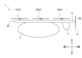
- the aircraft may further include a vertical tail that extends downward and is located at the rear of the lower part of the rod-shaped support member, and the tip of the vertical tail may be located below the plane of rotation of the propulsion propeller.
- the control unit may control the forward-most rotor during forward flight so that its rotation plane is tilted forward relative to the direction of travel, allowing it to function for propulsion in addition to or instead of the propulsion propeller.
- the control unit may control the rotation speed and/or the pitch angle of the blades of the forward-most rotor so that the lift and air resistance of the forward-most rotor are minimized during forward flight.
- the rotors are arranged in equal numbers on each of the rod-shaped support members to form multiple rotor groups each consisting of a pair of left and right rotors, and the number of blades of a rotor belonging to one of the multiple rotor groups may be different from the number of blades of a rotor belonging to the other rotor groups.
- the present invention allows for a vertical take-off and landing aircraft that can be made compact and fast.
- FIG. 1 is a schematic perspective view of a vertical take-off and landing aircraft according to a first embodiment of the present invention.
- FIG. FIG. 1 is a schematic plan view of a vertical take-off and landing aircraft of a first embodiment.
- FIG. 1 is a schematic side view of a vertical take-off and landing aircraft of a first embodiment.
- FIG. 2 is a block diagram showing the configuration of a control system for a rotor of a vertical take-off and landing aircraft according to each embodiment of the present invention.
- FIG. 4 is a diagram for explaining rotor control in a vertical take-off and landing aircraft according to each embodiment of the present invention.
- FIG. 4 is a diagram for explaining rotor control in a vertical take-off and landing aircraft according to each embodiment of the present invention.
- FIG. 4 is a diagram for explaining rotor control in a vertical take-off and landing aircraft according to each embodiment of the present invention.
- FIG. 4 is a control flow diagram of a control unit in the vertical take-off and landing aircraft of each embodiment of the present invention.
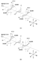
- FIG. 1A is a conceptual diagram of the flow field interference of the front and rear rotors in a vertical take-off and landing aircraft that does not perform the rotation speed control of the present invention
- FIG. 1B is a conceptual diagram of the flow field interference of the front and rear rotors in a vertical take-off and landing aircraft of each embodiment that performs the rotation speed control of the present invention.
- FIG. 4 is a schematic plan view of a vertical take-off and landing aircraft according to a second embodiment of the present invention.
- 1A is a conceptual diagram of rotor flow field interference in a vertical take-off and landing aircraft of the first embodiment
- FIG. 1B is a conceptual diagram of rotor flow field interference in a vertical take-off and landing aircraft of the second embodiment.
- 13A and 13B are schematic side views of a vertical take-off and landing aircraft according to a third embodiment of the present invention.
- FIG. 11 is a cross-sectional view of a fixed wing for illustrating the movement of a moving wing of a vertical take-off and landing aircraft according to a fourth embodiment of the present invention.
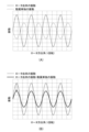
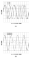
- 13A and 13B are graphs illustrating changes in vibration of the entire vertical take-off and landing aircraft caused by harmonic vibration of the rotor blades of the vertical take-off and landing aircraft according to the fourth embodiment.
- FIG. 1A is a schematic side view showing the state of downdraft below the rotor that occurs during takeoff and landing in a vertical take-off and landing aircraft of the first embodiment
- FIG. 1B is a schematic side view showing the state of downdraft below the rotor that occurs during takeoff and landing in a vertical take-off and landing aircraft of a fifth embodiment of the present invention
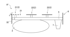
- FIG. 13 is a schematic side view of a vertical take-off and landing aircraft according to a sixth embodiment of the present invention.
- FIG. 23 is a schematic side view of a vertical take-off and landing aircraft according to a seventh embodiment of the present invention.
- FIG. 13 is a schematic plan view of a vertical take-off and landing aircraft according to a ninth embodiment of the present invention.
- FIG. 13A is a graph showing sound pressure fluctuations during rotor rotation due to differences in the number of rotor blades
- FIG. 13B is a graph showing sound pressure fluctuations during rotor rotation in each of the first and eighth embodiments.
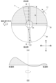
- 5A and 5B are conceptual diagrams for explaining a lift offset state of a rotor.
- FIG. 1 is a schematic perspective view of a vertical take-off and landing aircraft according to a first embodiment of the present invention.
- FIG. 2 is a schematic plan view of the vertical take-off and landing aircraft of the first embodiment.
- FIG. 3 is a schematic side view of the vertical take-off and landing aircraft of the first embodiment.
- FIG. 4 is a block diagram showing the configuration of the rotor control system of the vertical take-off and landing aircraft.
- the vertical take-off and landing aircraft 1 is a lift-and-cruise type multi-rotor vertical take-off and landing aircraft equipped with multiple rotors for vertical lift (hereinafter simply referred to as "rotors") and propulsion propellers.
- the direction of movement of the vertical take-off and landing aircraft 1 when it moves horizontally is defined as the forward direction, and the opposite direction is defined as the backward direction.
- the direction to the right of the width of the vertical take-off and landing aircraft 1 when viewed from the vertical take-off and landing aircraft 1 facing forward is defined as the right direction
- the direction to the left is defined as the left direction.
- the vertically upward direction is defined as the upward direction
- the vertically downward direction is defined as the downward direction.
- the front-rear direction, the left-right direction, and the up-down direction are mutually perpendicular.
- the plan view of the vertical take-off and landing aircraft 1 refers to the vertical take-off and landing aircraft 1 as viewed from above.
- the "outer side in the left-right direction” refers to the side away from the vertical center line A (see FIG. 2) that divides the vertical take-off and landing aircraft 1 in half in the left-right direction (width direction) when viewed in a plan view
- the “inner side in the left-right direction” refers to the side approaching the vertical center line A when viewed in a plan view
- the “rotation direction” of the rotor 2 refers to the rotation direction when viewed in a plan view.
- the vertical take-off and landing aircraft 1 has a fuselage 3, two fixed wings 4, a pair of left and right rod-shaped support members 5, multiple rotors 2 (six in this embodiment), two propulsion propellers 6, and two vertical tails 7.
- the fuselage 3 has a long shape in the front-to-rear direction and a streamlined shape that reduces air resistance during forward flight.
- a cockpit may be provided in the fuselage 3.
- the vertical take-off and landing aircraft 1 may be a manned aircraft or an unmanned aircraft controlled by a ground operator via wireless communication.
- the fixed wings 4 extend in the left-right direction and connect a pair of left and right rod-shaped support members 5R and 5L, which will be described later.
- the two fixed wings 4 are located at the front and rear of the fuselage 3, respectively, and are connected to the fuselage 3.
- the fixed wing 4 located at the front is called the front fixed wing 41
- the fixed wing 4 located at the rear is called the rear fixed wing 42, and when there is no need to distinguish between the two, they are referred to as fixed wings 4.
- the fixed wings 4 generate part of the lift.
- a pair of left and right moving wings 8 may be provided at the rear end of each fixed wing 4. The moving wings 8 will be described later.
- the mounting angle of the rear fixed wing 42 may be set to be about 1 degree larger than the mounting angle of the forward fixed wing 41. This allows the lift generated by the fixed wing 4 to be larger at the rear of the aircraft than at the front, generating a nose-down moment for the aircraft, which contributes to improving the static stability of the aircraft.
- the lift generated by the rear fixed wing 42 is reduced due to the downwash generated by the forward fixed wing 41, but by making the mounting angle of the rear fixed wing 42 larger than that of the forward fixed wing 41, the lift generated by the rear fixed wing 42 can be corrected and secured.
- the pair of left and right rod-shaped support members 5 have a shape that extends in the front-rear direction, and are provided on both the left and right sides of the fuselage 3 in a plan view.
- the rod-shaped support member located on the right side is given the symbol 5R
- the rod-shaped support member located on the left side is given the symbol 5L, but when there is no need to distinguish between them, they are referred to as rod-shaped support members 5.
- the rod-shaped support members 5 when the rod-shaped support members 5 "extend in the front-rear direction,” it is not limited to the rod-shaped support members 5 extending parallel to the front-rear direction, but only needs to extend in the front-rear direction as a whole, and may be curved like the rod-shaped support member 5A of the second embodiment described below. In this embodiment, the rod-shaped support members 5 have a shape that extends in a straight line parallel to the front-rear direction.
- the right side rod-shaped support member 5R is fixed to the right end side of the front fixed wing 41 and the right end side of the rear fixed wing 42.
- the left side rod-shaped support member 5L is fixed to the left end side of the front fixed wing 41 and the left end side of the rear fixed wing 42.
- the rod-shaped support member 5 supports the rotor 2 at its upper part, the vertical stabilizer 7 at its lower rear part, and the propulsion propeller 6 at its rear part.
- Two or more rotors 2 are arranged in the front-rear direction on each of the pair of left and right rod-shaped support members 5R and 5L.
- "Two or more rotors are arranged in the front-rear direction” includes a form in which two or more rotors are arranged on the same straight line parallel to the front-rear direction, as well as a form in which two or more rotors are arranged on a curved line extending in the front-rear direction, as long as two or more rotors are arranged in the front-rear direction overall.
- three rotors 2 are arranged on each rod-shaped support member 5, for a total of six rotors 2.
- the centers of the three rotors 2 arranged on each rod-shaped support member 5 are located on the same straight line parallel to the fore-aft direction.
- the centers of each rotor 2 are located at the same distance from the vertical center line A in the left-right direction, and are also in the same position in the up-down direction.
- the rotors 2 are arranged in equal numbers on the top of each rod-shaped support member 5.
- the three rotors 2 arranged on the right rod-shaped support member 5R are referred to as the right first rotor 21R, the right second rotor 22R, and the right third rotor 23R, from front to rear.
- the three rotors 2 arranged on the left rod-shaped support member 5L are referred to as the left first rotor 21L, the left second rotor 22L, and the left third rotor 23L, from front to rear. When there is no need to distinguish between them, they are referred to as rotors 2.
- the right first rotor 21R and the left first rotor 21L, the right second rotor 22R and the left second rotor 22L, and the right third rotor 23R and the left third rotor 23L are each located at the same position in the fore-and-aft direction and form a pair.
- the vertical take-off and landing aircraft 1 has three rotor groups consisting of pairs of left and right rotors 2.
- the rotor group consisting of the right first rotor 21R and the left first rotor 21L is called the first rotor group 210
- the rotor group consisting of the right second rotor 22R and the left second rotor 22L is called the second rotor group 220
- the rotor group consisting of the right third rotor 23R and the left third rotor 23L is called the third rotor group 230.
- the rotors 2 are rotors for vertical ascent and descent. Each rotor 2 rotates in a specified direction to generate lift (upward thrust) during vertical ascent, vertical descent, and hovering (stopping in the air). Furthermore, each rotor 2 does not stop rotating during forward flight (horizontal flight), but continues to rotate to generate lift. Thus, in this embodiment and each embodiment described below, the rotors 2, together with the fixed wings 4, are responsible for generating lift during forward flight. Furthermore, the rotation speed of the rotors 2 and the pitch angle of the blades 25 are individually controlled for each rotor 2. The direction of rotation of the rotors 2 is set according to the rotor's position.
- the rotor is used to generate lift during forward flight, so there is no need to rely on the fixed wing for the total aircraft lift, and the span length (width) of the fixed wing can be reduced, and the overall width size of the vertical take-off and landing aircraft can be reduced.
- the relationship between the forward rate (flight speed/wingtip speed) and the effective lift-to-drag ratio of the rotor is used to control the rotor rotation speed and the pitch angle of the blades, thereby suppressing the deterioration of rotor performance due to flow field interference and improving rotor performance.
- the proportion of lift generated by the fixed wing in the total aircraft lift can be reduced, making it possible to reduce the size of the fixed wing and therefore the vertical take-off and landing aircraft.
- a vertical take-off and landing aircraft with fixed wings is given as an example, but the present invention can also be applied to vertical take-off and landing aircraft without fixed wings.
- the fixed wing By generating lift during forward flight only with the rotor, the fixed wing can be omitted, making it possible to reduce the size of the vertical take-off and landing aircraft.
- the rear rotor In two rotors adjacent in the longitudinal direction, during forward flight, the rear rotor is affected by a slightly downward wake (downwash) generated by the front rotor. This is called flow field interference. Generally, due to flow field interference, the rear rotor needs to increase rotor rotational power to generate the lift required for that rotor, which reduces the performance of the rear rotor.
- the rotor is rotated in a predetermined direction during forward flight, and the rotor speed and blade pitch angle are controlled to achieve a forward rate (flight speed/wingtip speed) at which the effective lift-to-drag ratio of the rotor is equal to or greater than a threshold value.
- a forward rate flight speed/wingtip speed
- each rotor 2 has a motor 28, a hub (not shown) connected to the output shaft of the motor 28, and a number of blades 25 attached to the hub.
- the motor 28 is a power source for rotating the rotor 2.
- the motor 28, a battery (not shown) that supplies power to the motor 28, and the control unit 10 are provided in the fuselage 3.
- Each rotor 2 has four blades 25.
- the rotation plane 30 of each rotor 2 is horizontal.
- One longitudinal end of the blade 25 is attached to the hub.
- the other longitudinal end of the blade 25 is the tip of the blade 25, which is called the blade tip 27.
- Each rotor 2 is configured so that the rotation speed is variable and the pitch angle of the blade 25 is variable.
- the pitch angle of the blade 25 is the angle of the blade surface with respect to the rotation axis of the rotor 2.
- the number of blades is not limited to four, and may be two or more.
- Figure 19(A) is a plan view of the rotor 2, showing the case where the rotation direction 11 is counterclockwise.
- Figure 19(B) shows a conceptual lift distribution in the plane of rotation 30 of the rotor 2 when the vertical take-off and landing aircraft 1 is viewed from the front of the vertical take-off and landing aircraft 1 in forward flight, along line B-B in Figure 19(A).
- Reference numeral 33 denotes the center of the plane of rotation 20.
- the area filled with fine dots on the right half of the rotation surface 30 is the area where the blades 25 rotate in a forward direction (towards the front of the aircraft), and is called the "forward side.”
- the plain area on the left half of the rotation surface 30 is the area where the blades 25 rotate in a backward direction (towards the rear of the aircraft), and is called the "reverse side.” Note that in a rotor that rotates clockwise, the right half of the rotation surface is the reverse side, and the left half is the forward side.
- the rotors 2 mounted on a vertical take-off and landing aircraft 1 during forward flight have different relative speeds on the blades 25 on the left and right sides of each rotor 2.
- the horizontal flight speed (V) and the rotational speed (r ⁇ ) in the rotor radial direction r are combined, so the relative speed on the blades is faster.
- the horizontal flight speed (V) and the rotational speed (r ⁇ ) cancel each other out, so the relative speed is slower.
- the rotor 2 generally generates greater lift on the forward side and less on the retreating side, creating a gap in the lift distribution when viewed over the entire rotation plane 30, and the point of action of the lift is shifted from the center (lift offset state).
- horizontal flight speed may simply be referred to as "flight speed”.
- the propulsion propellers 6 are disposed at the rear of each of the pair of left and right rod-shaped support members 5R and 5L.
- the propulsion propeller 6 disposed on the right rod-shaped support member 5R is referred to as the right propulsion propeller 6R
- the propulsion propeller 6 disposed on the left rod-shaped support member 5L is referred to as the left propulsion propeller 6L
- propulsion propellers 6 when there is no need to particularly distinguish between the two, they are referred to as propulsion propellers 6.
- the right first rotor 21R, the right second rotor 22R, the right third rotor 23R, and the right propulsion propeller 6R are positioned on a straight line parallel to the fore-and-aft direction.
- the left first rotor 21L, the left second rotor 22L, the left third rotor 23L, and the left propulsion propeller 6L are positioned on the same straight line parallel to the fore-and-aft direction.
- each propulsion propeller 6 has a motor 68, a hub (not shown) connected to the output shaft of the motor 68, and a number of blades 65 attached to the hub.
- the motor 68 is a power source for rotating the propulsion propeller 6.
- the motor 68 and a battery (not shown) that supplies power to the motor 68 are provided in the fuselage 3.
- the mounting position of the battery is not necessarily limited to inside the fuselage.
- the battery may be arranged as close to the individual motors as possible.
- the battery may also be distributed within or under the support member.
- each propulsion propeller 6 has four blades 65.
- the rotation plane of each propulsion propeller 6 is vertical.
- the propulsion propeller 6 generates a forward thrust by the rotation of the blades 65, and the vertical take-off and landing aircraft 1 is capable of moving forward (forward flight).
- thrust is generated by the propellers 6, and lift is generated by the multiple rotors 2 and fixed wings 4, making it possible to achieve high speeds.
- the vertical tail 7 is connected to the lower rear of each of the pair of left and right rod-shaped support members 5R and 5L.
- the vertical tail 7 connected to the right rod-shaped support member 5R and extending downward is called the right vertical tail 7R
- the vertical tail 7 connected to the left rod-shaped support member 5L and extending downward is called the left vertical tail 7L.
- the vertical tail 7 is responsible for maintaining the lateral stability of the vertical take-off and landing aircraft 1.
- the vertical tail may be provided extending upward from the top of the rod-shaped support members 5.
- the vertical take-off and landing aircraft 1 includes a control unit 10 that controls the rotor 2 and the propulsion propeller 6, a memory device 16, and sensors 17.
- Sensors 17 are composed of various sensors that detect the flight state of vertical take-off and landing aircraft 1. Sensors 17 include, for example, a gyro sensor that detects the angle of the aircraft, an acceleration sensor that detects the acceleration of the aircraft, an airspeed indicator, a GPS, etc. From the sensing results of sensors 17, the attitude angle (pitch, roll, yaw), flight speed, position, etc. of the aircraft are detected. Sensing result information from sensors 17 is output to control unit 10.
- the vertical take-off and landing aircraft 1 is basically controlled in one of the ascending mode, forward flight mode, and hovering mode.
- the ascending mode is a control mode when the vertical take-off and landing aircraft 1 ascends or descends vertically.
- the vertical take-off and landing aircraft 1 ascends vertically at take-off and descends vertically at landing.
- the forward flight mode is a control mode when the aircraft flies forward while maintaining a horizontal attitude.
- the forward flight mode further includes a constant rotation speed mode in which the rotor rotation speed is controlled to be constant, and a variable rotation speed mode in which the rotor rotation speed can be changed.
- the hovering mode is a control mode when hovering. Note that in this embodiment, an example of ascending or descending vertically is given, but it may also ascend or descend diagonally like a fixed-wing aircraft.
- the aircraft ascends vertically (or ascends diagonally) in ascent mode, and when it reaches a certain altitude, the propulsion propeller 6 is activated and it transitions to forward flight mode.
- forward flight mode it flies in a constant speed mode with a constant rotor rotation speed until it reaches a predetermined flight speed (100 km/h (approximately 28 m/s) in this embodiment), and when it reaches or exceeds the predetermined flight speed (100 km/h in this embodiment), it transitions to a variable speed mode, and the rotor rotation speed and blade pitch angle according to the present invention are controlled.
- the aircraft reduces its flight speed in forward flight mode, and when the flight speed falls below the predetermined flight speed, it changes from the variable speed mode to the constant speed mode, and further gradually reduces its flight speed. It then transitions to ascent mode, descends vertically, and lands.
- the rotor rotation speed in the variable speed mode of the forward flight mode is controlled to be smaller than the rotor rotation speed in the ascent mode and the constant speed mode of the forward flight mode.
- the control unit 10 individually controls each rotor 2 and each propulsion propeller 6 according to each mode.
- the control unit 10 controls the rotation speed of the propulsion propellers 6, and controls the flight speed of the vertical take-off and landing aircraft 1.
- the control unit 10 controls the rotation speed of the rotor 2 and the pitch angle of the blades 25.
- the control unit 10 In forward flight mode, when flying forward at a flight speed of 100 km/h or more, the control unit 10 rotates the rotor 2 in a direction corresponding to its position, and uses flight speed information to control the rotation speed of the rotor 2 and the pitch angle of the blades 25 so that the forward rate (flight speed/tip speed) is such that the effective lift-to-drag ratio of the rotor is equal to or greater than a threshold value.
- control unit 10 uses the flight speed information to calculate the range of rotor rotation speeds based on first data prepared in advance that indicates the relationship between the effective lift-to-drag ratio of the rotor and the forward advance rate (flight speed/wing tip speed) so that the forward advance rate is equal to or greater than a threshold value.
- the control unit 10 uses the flight speed information to calculate the range of blade pitch angles that will generate the necessary lift for the rotor within the calculated range of rotor rotation speeds.
- the control unit 10 determines the rotation speeds of each rotor and the pitch angles of the blades within the calculated range of rotor rotation speeds and the range of blade pitch angles, and controls the rotor 2 based on the determined rotation speeds of the rotor 2 and pitch angles of the blades 25.
- the calculation of the rotor rotation speed range and the blade pitch angle range, as well as the determination of the rotor rotation speed and blade pitch angle, uses data stored in the storage device 16, which will be described later.
- the control unit 10 may determine the rotation speed of the rotor 2 and the pitch angle of the blades 25 so as to maintain a horizontal attitude, taking into account the attitude information of the vertical take-off and landing aircraft 1 in addition to the data stored in the storage device 16.
- Flight speed information and attitude information of the vertical take-off and landing aircraft 1 can be obtained using the sensing results of the sensors 17.
- the flight speed information and attitude information are obtained in real time.
- control unit 10 controls the rotation direction of each rotor in accordance with the arrangement position of the rotor 2.
- the rotation direction of a rotor is determined so as to reduce flow field interference according to the downwash distribution of the rotor in front of it.
- FIGS. 5 and 6 are examples of data stored in the storage device 16 used to control the rotor 2.
- the storage device 16 stores rotation speed calculation data 161 as first data and pitch angle calculation data 162 as second data.
- FIG. 5 shows the rotation speed calculation data 161.
- FIGS. 6(A) and (B) show conceptual pitch angle calculation data 162.
- the rotation speed calculation data 161 and pitch angle calculation data 162 are prepared in advance and stored in the storage device 16.
- the first data, 161 for calculating the rotation speed is used to calculate the range of the rotor rotation speed to minimize the degradation of aerodynamic performance due to flow field interference.
- the data 161 for calculating the rotation speed indicates the relationship between the forward advance rate and the effective lift-to-drag ratio of the rotor.
- the inventors have discovered a correlation between the rotor's effective lift-drag ratio and forward forward rate, where when a vertical take-off and landing aircraft 1 equipped with multiple rotors 2 for vertical lift and propulsion propellers 6 is flying forward at a flight speed of 100 km/h or more, as shown in the rotation speed calculation data 161 in FIG. 5, and the forward forward rate (flight speed/rotor tip speed) is a predetermined value (0.5) or more, the rotor's effective lift-drag ratio becomes stable at or above a threshold value.
- the rotation speed calculation data 161 is data on the effective lift-to-drag ratio (L/D E ) of the rotor 2 relative to the forward advance rate ( ⁇ ).
- the forward advance rate ( ⁇ ) is expressed as the ratio of the horizontal flight speed (V) divided by the wing tip speed R ⁇ (R is the rotor radius, and ⁇ is the rotation speed).
- the wing tip speed is the speed of the wing tip 27 corresponding to the tip of the blade 25.
- the effective lift-to-drag ratio (L/D E ) of the rotor 2 is the ratio of the lift force L to the effective drag force D E.
- the effective lift-to-drag ratio of the rotor 2 is an index showing the performance of the rotor, and the larger the effective lift-to-drag ratio, the smaller the air resistance, and the higher the energy efficiency and the better the rotor performance.
- the effective drag force D E is defined as follows:
- the effective lift-drag ratio tends to increase as the forward advance ratio value increases. Furthermore, when the forward advance ratio is 0.5 or more, the effective lift-drag ratio of the rotor stabilizes to be in the range of approximately 6.0 to 6.5. In other words, by controlling the rotor 2 at a rotor rotation speed that results in a forward advance ratio (0.5 or more) that results in the effective lift-drag ratio of the rotor being equal to or greater than a threshold value (the threshold value is 6.0 in the example shown in FIG.
- a higher forward advance ratio for a certain flight speed means a lower rotor rotation speed, and by reducing the rotation speed, the effective lift-drag ratio of the rotor can be increased.
- the “threshold” of "the rotor's effective lift-drag ratio is equal to or greater than the threshold” refers to the value when the rotor's effective lift-drag ratio begins to stabilize, and in the example shown in FIG. 5, the threshold is 6.0.
- the threshold can be changed depending on the position of the rotor 2. For example, when the rotors are arranged on the same line as in this embodiment, the threshold of the rotor's effective lift-drag ratio is lower for the third rotor 23 than for the first rotor 21 and the second rotor 22, but the shape of the graph (see FIG. 5) showing the correlation between the forward advance rate and the rotor's effective lift-drag ratio is similar, and the manner of change is the same.
- the rotor's effective lift-drag ratio is equal to or greater than the threshold, that is, the rotor performance is stable, when the forward advance rate is 0.5 or greater.
- the reason why the threshold of the effective lift-drag ratio is lower for the third rotor 23 is that the third rotor 23 is affected by the downdraft of the first rotor 21 and the second rotor 22, as shown in FIG. 10(A).
- the range of rotation speeds for each rotor 2 can be calculated using the same rotation speed calculation data 161, but the storage device 16 may store, for example, separate rotation speed calculation data 161 for the first rotor 21 and second rotor 22, and the third rotor 23.
- the pitch angle calculation data 162 as the second data is used to calculate the range of the pitch angle of the blades 25, and to determine the rotation speed of the rotor 2 and the pitch angle of the blades 25.
- the pitch angle calculation data 162 is data that indicates the relationship between the rotation speed of the rotor 2, the pitch angle of the blades 25, and the effective lift-to-drag ratio of the rotor 2.
- the control unit 10 uses the flight speed information and, based on the pitch angle calculation data 162, calculates the pitch angle range of the blades 25 that will generate the lift required for the rotor 2, within the range of the rotor rotation speed calculated using the rotation speed calculation data 161. Then, within the calculated range of the rotor rotation speed and pitch angle, it determines the rotation speed of the rotor 2 and the pitch angle of the blades 25 so that the effective lift-to-drag ratio of the rotor is optimized.
- the pitch angle calculation data 162 includes data showing the relationship between the blade pitch angle (blade pitch angle) and the rotor rotation speed shown in FIG. 6(A), and data showing the relationship between the blade pitch angle and the rotor effective lift-drag ratio shown in FIG. 6(B).
- the horizontal axis showing the blade pitch angle in the data shown in FIG. 6(A) corresponds to the horizontal axis showing the blade pitch in the data shown in FIG. 6(B).
- FIG. 6(A) shows the relationship between the pitch angle and the rotation speed that can generate the same lift. For example, even if the rotor rotation speed is changed, the blade pitch angle can be adjusted based on FIG. 6(A) according to the rotation speed to obtain the same lift.
- the data (pitch angle calculation data 162) showing the relationship between the rotor rotation speed, the blade pitch angle, and the rotor effective lift-drag ratio shown in FIG. 6(A) and (B) differs for each flight speed.
- the storage device 16 pre-stores the pitch angle calculation data 162 for each flight speed.
- Fig. 10(A) is a partial plan view of the right side of the vertical take-off and landing aircraft 1 of this embodiment for explaining the relationship between the direction of rotation and flow field interference.
- Fig. 7 is a control flow diagram by the control unit 10.
- Figs. 8(A) and (B) are conceptual diagrams for explaining the flow field interference of two rotors positioned adjacent to each other in the front-to-rear direction on the same straight line parallel to the front-to-rear direction, showing the lift distribution and downwash distribution generated on the rotor rotation surface. In the explanation using Figs.
- the rotor located at the front of the two rotors 2 (hereinafter referred to as the front rotor) is given the symbol 2F
- the rotor located at the rear is given the symbol 2R.
- Figure 8(A) is a conceptual diagram of flow field interference in a multi-rotor aircraft without propellers as a comparative example, showing the case where rotor speed control according to the present invention is not performed.
- the rotors tilt forward during forward flight, and the rotors must generate lift and thrust simultaneously, resulting in a forward forward ratio of, for example, about 0.2 to 0.4.
- Figure 8(A) shows a conceptual diagram of flow field interference when, for example, the forward forward ratio is about 0.3 and the rotor effective lift-to-drag ratio is about 4.
- FIG. 8(B) is a conceptual diagram of flow field interference when controlling the rotor speed according to the present invention, where the forward advance rate is 0.5 and the rotor effective lift-to-drag ratio is approximately 6.
- the vertical take-off and landing aircraft according to this embodiment and each of the embodiments described below are equipped with a propeller 6, which provides thrust during forward flight, and the multiple rotors 2 are configured to contribute only to generating lift. Therefore, during forward flight at a flight speed equal to or greater than a predetermined speed, the rotor 2 speed can be changed to decrease, and the forward advance rate can be increased.
- the control unit 10 controls the two rotors 2 so that their rotation directions are opposite to each other.
- the two rotors 2 adjacent in the fore-aft direction are the right first rotor 21R and the right second rotor 22R, the right second rotor 22R and the right third rotor 23R, the left first rotor 21L and the left second rotor 22L, and the left second rotor 22L and the left third rotor 23L.
- the right-side first rotor 21R and the right-side third rotor 23R are controlled to rotate counterclockwise, and the right-side second rotor 22R is controlled to rotate clockwise.
- the left-side first rotor 21L and the left-side third rotor 23L are controlled to rotate clockwise, and the left-side second rotor 22L is controlled to rotate counterclockwise.
- the direction of rotation of the rotors is determined according to the position of each rotor, so that the forward side (left half) of the right second rotor 22R is located immediately behind the retreating side (left half) of the right first rotor 21R, and the forward side (right half) of the right third rotor 23R is located immediately behind the retreating side (right half) of the right second rotor 22R.
- the direction of rotation of the rotors is determined according to the position of each rotor, so that the forward side (right half) of the left second rotor 22L is located immediately behind the retreating side (right half) of the left first rotor 21L, and the forward side (left half) of the left third rotor 23L is located immediately behind the retreating side (left half) of the left second rotor 22L.
- control unit 10 When the control unit 10 enters forward flight mode and begins forward flight at a flight speed equal to or greater than a predetermined speed (100 km/h), it uses flight speed information based on the sensing results acquired by the sensors 17 to calculate the range of rotor rotation speeds at which the rotor's effective lift-to-drag ratio is equal to or greater than a threshold, based on the rotation speed calculation data 161 in FIG. 5 (ST1). Specifically, in the example shown in FIG. 5, the control unit 10 uses flight speed information to calculate the range of rotor 2 rotation speeds, based on the rotation speed calculation data 161, so that the forward ratio is 0.5 or greater, at which the rotor's effective lift-to-drag ratio is 6 or greater.
- a predetermined speed 100 km/h
- the downwash distribution 12 can also be adjusted so that there is large downwash behind the forward moving side of the front rotor 2F and no downwash is generated or nearly so behind the retreating side of the front rotor 2F.
- the forward side of the rotation surface 30 of the rear rotor (e.g., right-side second rotor 22R) is positioned behind the backward side of the rotation surface 30 of the front rotor (e.g., right-side first rotor 21R) in two rotors adjacent in the fore-aft direction.
- the forward side of the rotation surface of the rear rotor where lift is mainly generated, is less susceptible to the downwash caused by the front rotor, reducing flow field interference.
- the third rotor 23 is affected by the downdraft from the first rotor 21 and the second rotor 22 in front of it. However, by reversing the rotational direction of the second rotor 22 and the third rotor 23, the third rotor 23 is less affected by the downdraft from the second rotor 22, although it is affected by the downdraft from the first rotor 21, which rotates in the same direction, and flow field interference can be reduced.
- the rotor speed range is set so that the effective lift-to-drag ratio of the rotor is equal to or greater than a threshold value, and the rotation direction of each rotor is controlled according to the rotor's position.
- control unit 10 acquires aircraft attitude information based on the sensing results from the sensors 17 (ST2).
- control unit 10 determines the lift required for each rotor 2 to keep the aircraft in a horizontal attitude based on the attitude information, and calculates the range of pitch angles of the blades 25 to obtain the required lift (ST3).
- control unit 10 uses the flight speed information to calculate the range of blade pitch angles corresponding to the range of rotor rotation speeds calculated in ST1, within the range in which the rotor 2 can obtain the required lift, based on the data showing the relationship between rotation speeds and blade pitch angles shown in Figure 6 (A).
- the control unit 10 determines the blade pitch angle that will maximize the effective lift-to-drag ratio within the calculated blade pitch angle range based on the data shown in FIG. 6(B), and determines the rotor speed according to the determined blade pitch angle (ST4).
- Each rotor 2 is controlled by the determined rotor speed and blade pitch angle. The rotor 2 generates the required lift by adjusting the blade pitch angle, and is adjusted so that the air resistance of the rotor 2 is reduced at a low rotation speed.
- control of the rotor rotation speed and blade pitch angle using the rotation speed calculation data 161 and pitch angle calculation data 162 is preferably used when the flight speed is 100 km/h or higher. If the above control is performed when the flight speed is less than 100 km/h, it is difficult for the rotor to generate sufficient lift.
- vertical take-off and landing aircraft are equipped with a rotor that generates lift during forward flight and a propeller, and rotor performance degradation due to flow field interference is suppressed and rotor performance is improved, making it possible to reduce the size and increase the speed.
- the aircraft may be a vertical take-off and landing aircraft without fixed wings 4.
- the rotor speed and blade pitch angle as described above, the rotor performance degradation caused by flow field interference can be suppressed, as in this embodiment, and miniaturization is possible.
- the vertical take-off and landing aircraft of this embodiment and each embodiment described below has six rotors 2. This improves redundancy and improves safety. Even if one rotor 2 fails, the remaining rotors 2 can continue to provide lift. If one rotor 2 fails, the rotor 2 paired with the failed rotor 2 may be stopped and four rotors 2 may be used, or the remaining five rotors 2 may continue to rotate.
- the vertical take-off and landing aircraft of this embodiment and each of the embodiments described below have six rotors 2, but it is sufficient if there are four or more rotors, and it is sufficient if multiple rotor groups consisting of a pair of two rotors on the left and right are arranged in the fore-and-aft direction to which the present invention can be applied.
- the rotor speed and blade pitch angle are controlled using the relationship between the forward movement rate and the rotor's effective lift-to-drag ratio.
- FIG. 9 is a plan view of the vertical take-off and landing aircraft 1A.
- the rod-shaped support members 5 have a shape that extends in a straight line parallel to the front-to-rear direction, but as in the vertical take-off and landing aircraft 1A shown in FIG. 9, the pair of left and right rod-shaped support members 5A and 5B may have a curved shape that curves in a plan view and extends in the front-to-rear direction.
- the right rod-shaped support member 5AR and the left rod-shaped support member 5AL each have a curved shape with the center in the front-to-rear direction convex outward in the left-to-right direction.
- the centers of the three rotors supported by the pair of left and right rod-shaped support members 5AR and 5AL are aligned in the front-rear direction, not on a straight line parallel to the front-rear direction, but offset left-right along a curve.
- the right-side second rotor 22R is offset left-right from the right-side first rotor 21R and the right-side third rotor 23R by the radius of the rotation surface 30.
- the right-side first rotor 21R and the right-side third rotor 23R are positioned at the same distance from the vertical center line A in the left-right direction.
- the left-side second rotor 22L is offset left-right from the left-side first rotor 21L and the left-side third rotor 23L by the radius of the rotation surface 30.
- the left-side first rotor 21L and the left-side third rotor 23L are positioned at the same distance from the vertical center line A in the left-right direction.
- the right-side first rotor 21R and the left-side first rotor 21L, the right-side second rotor 22R and the left-side second rotor 22L, and the right-side third rotor 23R and the left-side third rotor 23L are paired to form the first rotor group 210, the second rotor group 220, and the third rotor group 230.
- the six rotors 2 are positioned at the same position in the vertical direction.
- each of the six rotors 2 will be described.
- the rotation direction of the rotors 2 is controlled to be in the following forms (1) and (2).
- the two rotors 2 adjacent in the front-rear direction are the right first rotor 21R and the right second rotor 22R, the right second rotor 22R and the right third rotor 23R, the left first rotor 21L and the left second rotor 22L, and the left second rotor 22L and the left third rotor 23L.
- the rotor located at the front is called the front rotor
- the rotor located at the rear is called the rear rotor.
- the rotational directions of the front and rear rotors are controlled to be the same, so that the front rotor is not positioned in front of the forward side of the rotational plane 30 of the rear rotor, and the backward side of the rotational plane 30 of the rear rotor is positioned behind the forward side of the rotational plane 30 of the front rotor.
- the rear rotor is less susceptible to the downdraft from the front rotor on the forward side of its rotational plane 30, where lift is mainly generated.
- each rotor is positioned so that no other rotor is located in front of the forward side of its own rotational plane, or, even if another rotor is located in front of it, the retreating side of the other rotor is located in front of the forward side of its own rotational plane.
- the positional relationship and rotational direction relationship between the right-side first rotor 21R and the right-side second rotor 22R, and the positional relationship and rotational direction relationship between the left-side first rotor 21L and the left-side second rotor 22L satisfy (1) above.
- the second rotor 22 rear rotor
- the second rotor 22 is less susceptible to the downdraft caused by the first rotor 21 (front rotor) on the forward direction side of its rotation plane 30 where lift is mainly generated.
- the positional relationship and rotational direction relationship between the right-side second rotor 22R and the right-side third rotor 23R, and the positional relationship and rotational direction relationship between the left-side second rotor 22L and the left-side third rotor 23L satisfy (2) above.
- the third rotor 23 (rear rotor) is less susceptible to the downdraft caused by the second rotor 22 (front rotor) on the forward direction side of its rotation plane 30 where lift is mainly generated.
- the rotation direction is controlled as described above, so that the right first rotor 21R and the right third rotor 23R rotate in opposite directions.
- the right first rotor 21R and the right third rotor 23R are arranged so that their centers are adjacent to each other on the same straight line parallel to the front-rear direction.
- the right third rotor 23R is affected by the downdraft of the right first rotor 21R, but in this embodiment, the rotation direction is controlled so that the retreating side, where the right first rotor 21R generates no lift or is in a state close to that, is located in front of the forward moving side of the right third rotor 23R, so that the right third rotor 23R is less affected by the downdraft of the right first rotor 21R. Therefore, the right third rotor 23R is less affected by the downdraft of both the right first rotor 21R and the right second rotor 22R, which are located in front of it. The same is true for the left side.
- some of the rotors are positioned further outboard in the left-right direction than the other rotors, so the width of the aircraft is larger than in the first embodiment, but as described above, all six rotors 2 can be positioned to avoid flow field interference, improving rotor performance.
- FIG 11(A) is a schematic side view of vertical take-off and landing aircraft 1B
- Figure 10(B) is a schematic side view of vertical take-off and landing aircraft 1B.
- both vertical take-off and landing aircraft 1B and 1C have a pair of left and right rod-shaped support members 5 that are linear and parallel to the fore-aft direction, and the three rotors provided on each rod-shaped support member 5 are positioned on the same straight line that is parallel to the fore-aft direction in a plan view.
- the first rotor 21 and the second rotor 22 are at the same vertical position.
- the third rotor 23 is located higher than the first rotor 21 and the second rotor 22.
- the height of the third rotor 23 may be adjusted by adding a structure 29 that changes the rotor height to the rod-shaped support member 5.
- the rotation direction of each rotor 2 is preferably determined taking into account the downwash distribution based on the conceptual diagram of flow field interference between the front and rear rotors as shown in FIG. 8(B).
- the three rotors 2 arranged on each rod-shaped support member 5 are positioned on the same straight line parallel to the front-rear direction in a plan view, and as shown in FIG. 11(A), the third rotor 23 is positioned higher than the first rotor 21 and the second rotor 22, so that the third rotor 23, which is the third rotor from the front, is less susceptible to the downdraft caused by the first rotor 21 and the second rotor 22 in front of it.
- the second rotor 22 is less susceptible to the downdraft caused by the first rotor 21.
- all rotors of the vertical take-off and landing aircraft 1B are configured to avoid flow field interference.
- flow field interference can be reduced.
- the first rotor 21 and the third rotor 23 are at the same vertical position.
- the second rotor 22 is located higher than the first rotor 21 and the third rotor 23 in the vertical direction.
- the rotor height of the second rotor 22 may be adjusted by adding a structure 29 that changes the rotor height to the rod-shaped support member 5.
- each rod-shaped support member 5 When the three rotors 2 arranged on each rod-shaped support member 5 are positioned on the same straight line parallel to the front-to-rear direction in a plan view, and the second rotor 22 is positioned above the first rotor 21 and the third rotor 23 as shown in Figure 11 (B), the rotation direction of the second rotor 22 on each rod-shaped support member 5 is the same as that of the first rotor 21, and the rotation direction of the third rotor 23 is the opposite rotation direction to that of the second rotor 22.
- the rotation direction of the right-side first rotor 21R and the right-side second rotor 22R is counterclockwise
- the rotation direction of the right-side third rotor 23R is clockwise
- the rotation direction of the left-side first rotor 21L and the left-side second rotor 22L is clockwise
- the rotation direction of the left-side third rotor 23L is counterclockwise.
- the second rotor 22 is positioned higher than the first rotor 21, the second rotor 22 is less susceptible to the effects of downdrafts caused by the first rotor 21.
- each rotor 2 As described above, the second rotor 22 and the third rotor 23 rotate in opposite directions.
- the forward movement side (left half of the rotation surface) of the rotation surface 30 of the right-side third rotor 23R is located behind the retreating side (left half of the rotation surface) of the rotation surface of the right-side second rotor 22R.
- the downdraft caused by the right-side second rotor 22R has a downdraft distribution in which no downdraft is generated or a state close to it behind the retreating side of the rotation surface 30 of the right-side second rotor 22R, and the right-side third rotor 23R is less susceptible to the downdraft of the right-side second rotor 22R. The same is true on the left side.
- the first rotor 21 and the third rotor 23, whose centers are adjacent to each other on the same straight line parallel to the front-rear direction, are at the same vertical position and rotate in opposite directions.
- the forward side (left half of the rotation surface) of the rotation surface 30 of the right third rotor 23R is located behind the retreating side (left half of the rotation surface) of the rotation surface of the right first rotor 21R.
- the downdraft caused by the right first rotor 21R has a downdraft distribution in which no downdraft is generated or a state close to it behind the retreating side of the rotation surface 30 of the right first rotor 21R, and the right third rotor 23R is less susceptible to the downdraft of the right first rotor 21R. Therefore, the right third rotor 23R is less susceptible to the downdraft of the right first rotor 21R and the right second rotor 22R located in front of it. The same is true on the left side.
- all rotors of the vertical take-off and landing aircraft 1C are configured to avoid flow field interference.
- flow field interference can be reduced.
- Figure 12 is a schematic cross-sectional view of the fixed blade 4 provided with the moving blade 8 taken along line XII-XII in Figure 1.
- Figure 13(A) is a conceptual diagram showing the vibration caused by the rotor (shown by thin solid lines) and the vibration of the moving blade alone (shown by dashed lines)
- Figure 13(B) is a conceptual diagram showing the vibration caused by the rotor (shown by thin solid lines) and the vibration caused by the combination of the vibration caused by the rotor and the harmonic vibration caused by the moving blade (shown by thick solid lines).
- each vibration corresponds to the fluctuation in lift generated in the fixed blade 4.
- the vibrations originating from the rotor 2 are generated by a lift distribution in which the lift is greater on the forward moving side on the rotation plane 30 of the rotor 2, and cause vibrations of the aircraft.
- the moving blades 8 may be configured to move up and down so as to generate harmonic vibrations in the opposite phase to the vibrations originating from the rotor 2.
- the vibrations of the aircraft can be reduced by generating vibrations in the opposite phase to the vibrations originating from the rotor 2 using the moving blades 8, as shown by the thick line in FIG. 13(B).
- the moving blades 8 are moved faster than the rotation speed of the rotor 2.
- the harmonic vibrations of the moving blades 8 are controlled at an integer multiple of the frequency of the rotation speed of the rotor 2, and harmonic control is performed to shift the phase of the frequency of the vibrations originating from the rotor.
- the vibrations of the aircraft can be reduced. This reduces the load on the aircraft, improving its durability and safety, and also reducing the risk of failure or malfunction of various devices such as sensors installed on vertical take-off and landing aircraft. It also reduces noise and improves passenger comfort.
- FIG. 14(A) is a schematic side view of a vertical take-off and landing aircraft 1 of the first embodiment
- FIG. 14(B) is a schematic side view of a vertical take-off and landing aircraft 1D of the fifth embodiment.
- each rotor 2 is disposed above the rod-shaped support member 5 as in FIG. 14(A), but each rotor 2 may be disposed below the rod-shaped support member 5 as in the vertical take-off and landing aircraft 1D shown in FIG. 14(B).
- the rotor 2 is disposed above the rod-shaped support member 5 as in the vertical take-off and landing aircraft 1 shown in FIG. 14(A)
- lift is generated in the rotor 2 during take-off and landing (vertical ascent and descent) or during hovering, downdraft occurs downwards of the rotor 2.
- This downdraft causes flow field interference with the rod-shaped support member 5, and the rod-shaped support member 5 generates a downward force on the aircraft that is opposite to the rotor lift. This is called downloading.
- This downloading requires the rotor 2 to generate even greater lift, and downloading causes deterioration of vertical take-off and landing performance and rotor performance during hovering.
- the rotor 2 may be placed below the rod-shaped support member 5, as shown in Figure 14 (B). With this configuration, the downdraft generated by the rotor 2 does not interfere with the flow field of the rod-shaped support member 5, and download can be avoided. This improves rotor performance. Furthermore, during forward flight, rotor performance is not affected whether the rotor 2 is above or below the rod-shaped support member 5.
- the rotor 2 When the aircraft is manned, it is preferable to mount the rotor 2 on the upper part of the rod-shaped support member 5, as shown in FIG. 14(A). This makes it difficult for passengers aboard the vertical take-off and landing aircraft 1 to see the rotor 2 through the windows provided in the fuselage 3, eliminating the psychological anxiety that may come from seeing the rotor 2 and the fear that it may fly off and strike, and providing the passengers with a visual sense of security. Furthermore, by mounting the rotor 2 on the upper part of the rod-shaped support member 5, it is easier to avoid contact between the rotor 2 and people or objects outside the vertical take-off and landing aircraft 1 that has landed on the ground, ensuring safety.
- FIG. 15 is a schematic side view of a vertical take-off and landing aircraft 1E according to the sixth embodiment.
- landing skids 19 may be attached to the lower part of the fuselage 3 so that the fuselage 3 does not come into direct contact with the ground E.
- the skids 19 are arranged, for example, in a pair in the left-right direction and extend parallel in the fore-aft direction.
- the skids 19 may be of a type that can be retracted into the fuselage 3.
- a vertical tail 7 extending downward is provided at the rear of the lower part of the rod-shaped support member 5.
- the tip 7a of the vertical tail 7 is preferably located below the rotation plane of the propulsion propeller 6 in the vertical direction. More preferably, as shown in FIG. 15, the inclination of an imaginary straight line L1 passing through the rearmost part 19a of the skid 19 and the lowest end of the rotation plane of the propulsion propeller 6 with respect to the horizontal ground surface E is made larger than the inclination of an imaginary straight line L2 passing through the rearmost part 19a of the skid 19 and the rearmost part of the tip 7a of the vertical tail 7 with respect to the horizontal ground surface E.
- This configuration prevents the propulsion propellers 6 from contacting the ground E when the aircraft lands, and at the same time prevents the propulsion propellers 6 from being damaged and scattered due to contact, thereby improving aircraft safety. Furthermore, in the event of a hard landing on the ground E due to attitude instability during landing, the vertical tail 7 touches the ground E before the propulsion propellers 6, preventing damage to the propulsion propellers 6. Furthermore, by attaching the vertical tail 7 to the bottom of the rod-shaped support member 5 and arranging each rotor 2 on the top of the rod-shaped support member 5, it is possible to suppress a decrease in attitude stability due to flow field interference from the downwash caused by the rotors 2, and to prevent a significant loss of directional stability during forward flight.
- the control unit 10 may control the plane of rotation of the forwardmost first rotor 21 (right first rotor 21R and left first rotor 21L) to be inclined forward with respect to the direction of travel, so that the first rotor 21 functions as a propulsion rotor in addition to or in place of the propulsion propeller 6. That is, during vertical take-off and landing (ascent mode), the control unit 10 controls the first rotor 21 so that the plane of rotation is in a horizontal position 31 (a position that is approximately vertical in the up-down direction). On the other hand, during forward flight (forward flight mode), the control unit 10 controls the plane of rotation to be inclined forward with respect to the direction of travel, for example, to be in a vertical position 32 that is approximately vertical with respect to the direction of travel.
- the rotor 2 mounted on the rod-shaped support member 5 generates a head-up moment during forward flight, which may cause the aircraft to change its attitude in the head-up direction, compromising aircraft stability.
- the first rotor 21 which is located at the very front of the aircraft, ahead of the aircraft's center of gravity, can be tilted forward during forward flight and made to function as a propulsion propeller, which can generate a head-down moment around the center of gravity at the same time as the thrust. This reduces the head-up moment and improves the aircraft's stability.
- the control unit 10 may control the rotor rotation speed and/or blade pitch angle of the first rotor 21, which is located at the very front of the aircraft, forward of the center of gravity, during forward flight, without stopping the rotation, so as to minimize lift and air resistance. This reduces the head-up moment and improves the stability of the aircraft.
- the first rotor 21 since the first rotor 21 has four blades 25, if the rotation of the first rotor 21 is completely stopped, the blades 25 will protrude in the left and right directions relative to the rod-shaped support member 5, causing large air resistance, but by constantly rotating the first rotor 21, it is possible to adjust the air resistance to be small.
- the number of blades on each rotor 2 is the same, but the number of blades on each rotor 2G may be different, as in the vertical take-off and landing aircraft 1G of this embodiment shown in FIG. 17. In this case, it is preferable to make the value obtained by multiplying the number of blades by the area of each blade equal for each rotor 2G, and it is easy to adjust each rotor 2G to obtain the same lift.
- Figure 17 is a schematic plan view of a vertical take-off and landing aircraft 1G of the ninth embodiment.
- Figure 18 (A) is a conceptual diagram showing sound pressure fluctuations, with the solid line showing the sound pressure fluctuations of a rotor with three blades, the dashed line showing the sound pressure fluctuations of a rotor with four blades, and the dashed line showing the sound pressure fluctuations of a rotor with five blades.
- Figure 18 (B) is a conceptual diagram showing sound pressure fluctuations, with the solid line showing the sound pressure fluctuations when the rotors have the same number of blades corresponding to the first embodiment, and the dashed line showing the sound pressure fluctuations when the rotors have different numbers of blades according to this embodiment.
- the vertical take-off and landing aircraft 1G has a first rotor group 210G consisting of two first rotors 21G (right first rotor 21GR and left first rotor 21GL) located at the very front, a second rotor group 220G consisting of two second rotors 22G (right second rotor 22GR and left second rotor 22GL) located approximately in the center in the fore-and-aft direction, and a third rotor group 230G consisting of two third rotors 23G (right third rotor 23GR and left third rotor 23GL) located at the very rear, for a total of six rotors.
- rotor 2G When no distinction is made between the rotors, they are referred to as rotor 2G.
- the position and direction of rotation of each rotor 2G are the same as those of the rotor 2 in the first embodiment.
- the first rotor 21G has three blades 25.
- the second rotor 22G has four blades 25.
- the third rotor 23G has five blades 25.
Landscapes
- Engineering & Computer Science (AREA)
- Aviation & Aerospace Engineering (AREA)
- Mechanical Engineering (AREA)
- Remote Sensing (AREA)
- Chemical & Material Sciences (AREA)
- Combustion & Propulsion (AREA)
- Toys (AREA)
Abstract
Description
2、2G…垂直昇降用のロータ、ロータ
3…胴体
4…固定翼
5、5A…棒状支持部材
6…推進プロペラ
7…垂直尾翼
7a…垂直尾翼の先端
8…動翼
10…制御部
11…ロータ回転方向
16…記憶装置
21…第1ロータ、ロータ、最も前方に位置するロータ
21R、21GR…右側第1ロータ、ロータ、最も前方に位置するロータ
21L、21GL…左側第1ロータ、ロータ、最も前方に位置するロータ
22…第2ロータ、ロータ
22R、22GR…右側第2ロータ、ロータ
22L、22GL…左側第2ロータ、ロータ
23…第3ロータ
23R、23GR…右側第3ロータ、ロータ
23L、23GL…左側第3ロータ、ロータ
25…ブレード
30…回転面
161…回転数算出用データ(第1のデータ)
162…ピッチ角算出用データ(第2のデータ)
210、210G…第1ロータ群
220、220G…第2ロータ群
230、230G…第3ロータ群
Claims (23)
- 前後方向に延び、左右両側に設けられた左右一対の棒状支持部材と、
推進プロペラと、
前記棒状支持部材それぞれに前後方向に2以上配置され、それぞれが複数のブレードを有し、所定の回転方向で回転して揚力を発生させる垂直昇降用のロータと、
前進飛行時に前記ロータを回転させ、前記ロータの実効揚抗比が閾値以上になる、飛行速度と前記ロータの翼端速度との比を表す前進率となるように、前記ロータの回転数及び前記ブレードのピッチ角を制御する制御部と
を具備する垂直離着陸機。 - 請求項1に記載の垂直離着陸機であって、
前記制御部は、
前記垂直離着陸機の飛行速度情報を取得し、
前記飛行速度情報を用い、予め準備した前記ロータの実効揚抗比と前記前進率との関係を示す第1のデータに基づいて、前記ロータの実効揚抗比が閾値以上になる前進率となるように、前記ロータの回転数の範囲を算出し、
前記飛行速度情報を用いて、前記算出したロータの回転数の範囲内で、前記ロータに必要な揚力を生じさせる前記ブレードのピッチ角の範囲を算出し、
算出した前記ロータの回転数の範囲内かつ前記ブレードのピッチ角の範囲内で、前記ロータの回転数及び前記ブレードのピッチ角を決定する
垂直離着陸機。 - 請求項2に記載の垂直離着陸機であって、
前記制御部は、
前記垂直離着陸機の姿勢情報を取得し、
前記姿勢情報を加味して、前記ロータの回転数と前記ブレードのピッチ角を決定する
垂直離着陸機。 - 請求項2に記載の垂直離着陸機であって、
予め準備した、前記第1のデータと、飛行速度毎の、前記ロータの回転数、前記ブレードのピッチ角及び前記ロータの実効揚抗比との関係を示す第2のデータとを記憶する記憶装置を更に具備し、
前記制御部は、
前記ロータの回転数の算出において、前記飛行速度情報を用い、前記第1のデータに基づいて、前記ロータの実効揚抗比が閾値以上になる前進率となる前記ロータの回転数の範囲を算出し、
前記ブレードのピッチ角の範囲の算出において、前記飛行速度情報を用い、前記第2のデータに基づいて、前記算出したロータの回転数の範囲内で、前記ロータに必要な揚力を生じさせる前記ブレードのピッチ角の範囲を算出する
垂直離着陸機。 - 請求項1に記載の垂直離着陸機であって、
前記ロータの実効揚抗比が閾値以上となる前進率は0.5以上である
垂直離着離着陸機。 - 請求項2に記載の垂直離着陸機であって、
前記ロータは、左右一対のロータからなるロータ群を複数形成するように、前記棒状支持部材それぞれに同数配置され、
前記制御部は、前記ロータそれぞれの回転数が前記算出したロータの回転数の範囲内となる条件下で、前記複数のロータ群のうち1つのロータ群に属するロータの回転数を、他のロータ群に属するロータの回転数と異なるように制御する
垂直離着陸機。 - 請求項1に記載の垂直離着陸機であって、
前記制御部は、所定速度以上の飛行速度での前進飛行時に、前記ロータの実効揚抗比が閾値以上になる前進率となるように、前記ロータの回転数及び前記ブレードのピッチ角を制御する
垂直離着陸機。 - 請求項7に記載の垂直離着陸機であって、
前記所定速度は100km/hである
垂直離着陸機。 - 請求項1に記載の垂直離着陸機であって、
前記制御部は、前進飛行時に、中心が前後方向に平行な同一直線上に前後に隣接して位置する2つの前記ロータを、互いの回転方向が逆となるように回転させる
垂直離着陸機。 - 請求項9に記載の垂直離着陸機であって、
前記ロータは、前記棒状支持部材それぞれに、その中心が前後方向に平行な同一直線上に位置するように3つ配置され、
右側の前記棒状支持部材に配置される3つのロータは、前方から後方にむかって順に並ぶ右側第1ロータ、右側第2ロータ及び右側第3ロータであり、
左側の前記棒状支持部材に配置される3つのロータは、前方から後方にむかって順に並ぶ左側第1ロータ、左側第2ロータ及び左側第3ロータであり、
前記制御部は、前記右側第1ロータ、前記右側第3ロータ、前記左側第2ロータを、上から見て回転方向が反時計回りとなるように回転させ、前記右側第2ロータ、前記左側第1ロータ及び前記左側第3ロータを、回転方向が時計周りとなるように回転させる
垂直離着陸機。 - 請求項1に記載の垂直離着陸機であって、
前記棒状支持部材それぞれに配置される2以上のロータのうち前後方向に隣り合って位置する2つのロータは、一方のロータの中心が他方のロータの中心よりも左右方向にずれて位置する
垂直離着陸機。 - 請求項11に記載の垂直離着陸機であって、
前記ロータは、前記棒状支持部材それぞれに、上下方向の位置が同じとなるように3つ配置され、
右側の前記棒状支持部材に配置される3つのロータは、前方から後方にむかって順に並ぶ右側第1ロータ、右側第2ロータ及び右側第3ロータであり、
左側の前記棒状支持部材に配置される3つのロータは、前方から後方にむかって順に並ぶ左側第1ロータ、左側第2ロータ及び左側第3ロータであり、
前記右側第2ロータは、前記右側第1ロータ及び前記右側第3ロータよりも左右方向外側に、前記ロータの回転面の半径分ずれて位置し、
前記左側第2ロータは、前記左側第1ロータ及び前記左側第3ロータよりも左右方向外側に、前記ロータの回転面の半径分ずれて位置し、
前記制御部は、前記右側第1ロータ、前記右側第2ロータ及び前記左側第3ロータを、上から見て回転方向が反時計回りとなるように回転させ、前記右側第3ロータ、前記左側第1ロータ及び前記左側第2ロータを、回転方向が時計周りとなるように回転させる
垂直離着陸機。 - 請求項1に記載の垂直離着陸機であって、
前記ロータは、前記棒状支持部材それぞれに3以上配置される
垂直離着陸機。 - 請求項13に記載の垂直離着陸機であって、
前記ロータは、左右一対のロータからなるロータ群を複数形成するように、前記棒状支持部材それぞれに同数配置され、
複数の前記ロータ群のうち1つのロータ群に属するロータは、他のロータ群に属するロータと上下方向の位置が異なる
垂直離着陸機。 - 請求項14に記載の垂直離着陸機であって、
前記ロータは、前記棒状支持部材それぞれに、平面視で、前後方向に平行な同一直線上に位置するように3つ配置され、
右側の前記棒状支持部材に配置される3つのロータは、前方から後方にむかって順に並ぶ右側第1ロータ、右側第2ロータ及び右側第3ロータであり、
左側の前記棒状支持部材に配置される3つのロータは、前方から後方にむかって順に並ぶ左側第1ロータ、左側第2ロータ及び左側第3ロータであり、
前記右側第1ロータ、前記右側第2ロータ、前記左側第1ロータ及び前記左側第2ロータは上下方向の位置が同じであり、前記右側第3ロータ及び前記左側第3ロータは、前記右側第1ロータ、前記右側第2ロータ、前記左側第1ロータ及び前記左側第2ロータよりも上方に位置し、
前記制御部は、前記右側第1ロータ、前記右側第3ロータ、前記左側第2ロータを、上から見て回転方向が反時計回りとなるように回転させ、前記右側第2ロータ、前記左側第1ロータ及び前記左側第3ロータを、回転方向が時計周りとなるように回転させる
垂直離着陸機。 - 請求項14に記載の垂直離着陸機であって、
前記ロータは、前記棒状支持部材それぞれに、平面視で、前後方向に平行な同一直線上に位置するように3つ配置され、
右側の前記棒状支持部材に配置される3つのロータは、前方から後方にむかって順に並ぶ右側第1ロータ、右側第2ロータ及び右側第3ロータであり、
左側の前記棒状支持部材に配置される3つのロータは、前方から後方にむかって順に並ぶ左側第1ロータ、左側第2ロータ及び左側第3ロータであり、
前記右側第1ロータ、前記右側第3ロータ、前記左側第1ロータ及び前記左側第3ロータは上下方向の位置が同じであり、前記右側第2ロータ及び前記左側第2ロータは、前記右側第1ロータ、前記右側第3ロータ、前記左側第1ロータ及び前記左側第3ロータよりも上方に位置し、
前記制御部は、前記右側第1ロータ、前記右側第2ロータ、前記左側第3ロータを、上から見て回転方向が反時計回りとなるように回転させ、前記右側第3ロータ、前記左側第1ロータ及び前記左側第2ロータを、回転方向が時計周りとなるように回転させる
垂直離着陸機。 - 請求項1に記載の垂直離着陸機であって、
胴体と、
前記胴体と結合し、前記左右一対の棒状支持部材を連結する左右方向に延在する固定翼
を更に具備する垂直離着陸機。 - 請求項17に記載の垂直離着陸機であって、
前記固定翼に配置された、前記ロータ由来の振動に対して逆位相の高調波振動を発生する動翼
を更に具備する垂直離着陸機。 - 請求項1に記載の垂直離着陸機であって、
前記ロータは、前記棒状支持部材の下部に配置される
垂直離着陸機。 - 請求項1に記載の垂直離着陸機であって、
前記棒状支持部材の下部後方に配置された下向きに延在する垂直尾翼を更に具備し、
前記垂直尾翼の先端は前記推進プロペラの回転面より下方に位置する
垂直離着陸機。 - 請求項1に記載の垂直離着陸機であって、
前記制御部は、前進飛行時に、最も前方に位置するロータを、その回転面を進行方向に対し前傾するように制御して、前記推進プロペラに加えて、又は、前記推進プロペラに替えて、推進用として機能させる
垂直離着陸機。 - 請求項1に記載の垂直離着陸機であって、
前記制御部は、前進飛行時に、最も前方に位置するロータの揚力と空気抵抗が最小となるように、前記最も前方に位置するロータの回転数及び/又は当該ロータのブレードのピッチ角を制御する
垂直離着陸機。 - 請求項1に記載の垂直離着陸機であって、
前記ロータは、左右一対のロータからなるロータ群を複数形成するように、前記棒状支持部材それぞれに同数配置され、
複数の前記ロータ群のうち1つのロータ群に属するロータの前記ブレードの数は、他のロータ群に属するロータと異なる
垂直離着陸機。
Priority Applications (1)
| Application Number | Priority Date | Filing Date | Title |
|---|---|---|---|
| EP24818994.6A EP4725839A1 (en) | 2023-06-08 | 2024-03-19 | Vertical takeoff and landing aircraft |
Applications Claiming Priority (2)
| Application Number | Priority Date | Filing Date | Title |
|---|---|---|---|
| JP2023-094449 | 2023-06-08 | ||
| JP2023094449A JP2024176151A (ja) | 2023-06-08 | 2023-06-08 | 垂直離着陸機 |
Publications (1)
| Publication Number | Publication Date |
|---|---|
| WO2024252755A1 true WO2024252755A1 (ja) | 2024-12-12 |
Family
ID=93795837
Family Applications (1)
| Application Number | Title | Priority Date | Filing Date |
|---|---|---|---|
| PCT/JP2024/010644 Ceased WO2024252755A1 (ja) | 2023-06-08 | 2024-03-19 | 垂直離着陸機 |
Country Status (3)
| Country | Link |
|---|---|
| EP (1) | EP4725839A1 (ja) |
| JP (1) | JP2024176151A (ja) |
| WO (1) | WO2024252755A1 (ja) |
Citations (8)
| Publication number | Priority date | Publication date | Assignee | Title |
|---|---|---|---|---|
| US10046853B2 (en) | 2014-08-19 | 2018-08-14 | Aergility LLC | Hybrid gyrodyne aircraft employing a managed autorotation flight control system |
| US20180305005A1 (en) * | 2017-04-24 | 2018-10-25 | AFS-DV VTOL Technologies Corporation | Vertical Take-Off and Landing Aircraft |
| US20190127056A1 (en) | 2017-10-27 | 2019-05-02 | Elroy Air, Inc. | Compound multi-copter aircraft |
| WO2019190263A1 (ko) * | 2018-03-29 | 2019-10-03 | 이호형 | 개량형 하이브리드 드론 |
| US20220041272A1 (en) * | 2020-08-07 | 2022-02-10 | Shanghai Autoflight Co., Ltd. | Vertical takeoff and landing aerial vehicle |
| CN115042968A (zh) | 2021-03-08 | 2022-09-13 | 沃科波特有限公司 | 垂直起降飞机 |
| JP2022148991A (ja) | 2021-03-25 | 2022-10-06 | 本田技研工業株式会社 | 航空機 |
| JP2022151924A (ja) | 2021-03-29 | 2022-10-12 | 本田技研工業株式会社 | 航空機 |
-
2023
- 2023-06-08 JP JP2023094449A patent/JP2024176151A/ja active Pending
-
2024
- 2024-03-19 EP EP24818994.6A patent/EP4725839A1/en active Pending
- 2024-03-19 WO PCT/JP2024/010644 patent/WO2024252755A1/ja not_active Ceased
Patent Citations (8)
| Publication number | Priority date | Publication date | Assignee | Title |
|---|---|---|---|---|
| US10046853B2 (en) | 2014-08-19 | 2018-08-14 | Aergility LLC | Hybrid gyrodyne aircraft employing a managed autorotation flight control system |
| US20180305005A1 (en) * | 2017-04-24 | 2018-10-25 | AFS-DV VTOL Technologies Corporation | Vertical Take-Off and Landing Aircraft |
| US20190127056A1 (en) | 2017-10-27 | 2019-05-02 | Elroy Air, Inc. | Compound multi-copter aircraft |
| WO2019190263A1 (ko) * | 2018-03-29 | 2019-10-03 | 이호형 | 개량형 하이브리드 드론 |
| US20220041272A1 (en) * | 2020-08-07 | 2022-02-10 | Shanghai Autoflight Co., Ltd. | Vertical takeoff and landing aerial vehicle |
| CN115042968A (zh) | 2021-03-08 | 2022-09-13 | 沃科波特有限公司 | 垂直起降飞机 |
| JP2022148991A (ja) | 2021-03-25 | 2022-10-06 | 本田技研工業株式会社 | 航空機 |
| JP2022151924A (ja) | 2021-03-29 | 2022-10-12 | 本田技研工業株式会社 | 航空機 |
Non-Patent Citations (2)
| Title |
|---|
| SAYAMA YUTO: "Numerical analysis of forward flight of rotors for multirotor aircraft", 2021 FUTURE ROTORCRAFT RESEARCH MEETING/ROTOR ANALYSIS TECHNOLOGY EXCHANGE MEETING, TOKYO UNIVERSITY OF AGRICULTURE AND TECHNOLOGY, JP, 16 March 2022 (2022-03-16), JP, pages 1 - 18, XP093246660, Retrieved from the Internet <URL:http://helijapan.org/pdf/kaisekigijyutu/FY2021/presen-5.pdf> * |
| SAYAMA, Y.SUGAWARA, HTANABE, YKAMEDA, M.: "Impact of Rear-Rotor Vertical Location on Aerodynamics of Multi-Rotor in Forward Flight", PROCEEDINGS OF 54TH FLUID DYNAMICS CONFERENCE/40TH AEROSPACE NUMERICAL SIMULATION SYMPOSIUM, 1 July 2022 (2022-07-01) |
Also Published As
| Publication number | Publication date |
|---|---|
| JP2024176151A (ja) | 2024-12-19 |
| EP4725839A1 (en) | 2026-04-15 |
Similar Documents
| Publication | Publication Date | Title |
|---|---|---|
| JP7598948B2 (ja) | 垂直離着陸航空機 | |
| EP3201711B1 (en) | Aircraft and method of orienting an airframe of an aircraft | |
| US8540184B2 (en) | Long-range aircraft with high forward speed in cruising flight | |
| US6089501A (en) | Tandem-rotor gyroplane | |
| US11472545B2 (en) | Propulsion system and aircraft with vertical take-off and landing-VTOL | |
| US20060113425A1 (en) | Vertical take-off and landing aircraft with adjustable center-of-gravity position | |
| KR20200058204A (ko) | 복합형 삼중 날개 분산추진 수직이착륙 항공기 | |
| JP2018086916A (ja) | 飛行体 | |
| JP2018020742A (ja) | 飛行体、改造キット、制御方法及び制御プログラム | |
| JP2009234551A (ja) | 主翼取り付け角変更装置を備えた垂直離着陸航空機 | |
| WO2024252755A1 (ja) | 垂直離着陸機 | |
| US20240158075A1 (en) | Flight vehicle | |
| GB2423971A (en) | Autogyro hovercraft | |
| JP7805545B1 (ja) | 表面効果翼形飛行体の飛行方法 | |
| JP7846844B1 (ja) | 表面効果翼形飛行体の飛行方法 | |
| WO2020183594A1 (ja) | テールシッタ式飛行体 | |
| WO2026039025A2 (en) | Vibration suppression utilizing surface actuation | |
| WO2025221340A2 (en) | Airborne vehicle having v-tail mounted propellers |
Legal Events
| Date | Code | Title | Description |
|---|---|---|---|
| 121 | Ep: the epo has been informed by wipo that ep was designated in this application |
Ref document number: 24818994 Country of ref document: EP Kind code of ref document: A1 |
|
| WWE | Wipo information: entry into national phase |
Ref document number: 2024818994 Country of ref document: EP |
|
| NENP | Non-entry into the national phase |
Ref country code: DE |
|
| ENP | Entry into the national phase |
Ref document number: 2024818994 Country of ref document: EP Effective date: 20260108 |
|
| ENP | Entry into the national phase |
Ref document number: 2024818994 Country of ref document: EP Effective date: 20260108 |
|
| ENP | Entry into the national phase |
Ref document number: 2024818994 Country of ref document: EP Effective date: 20260108 |
|
| ENP | Entry into the national phase |
Ref document number: 2024818994 Country of ref document: EP Effective date: 20260108 |
|
| ENP | Entry into the national phase |
Ref document number: 2024818994 Country of ref document: EP Effective date: 20260108 |
|
| WWP | Wipo information: published in national office |
Ref document number: 2024818994 Country of ref document: EP |