WO2024252742A1 - 二次電池の劣化予測システムおよび二次電池の劣化予測方法 - Google Patents
二次電池の劣化予測システムおよび二次電池の劣化予測方法 Download PDFInfo
- Publication number
- WO2024252742A1 WO2024252742A1 PCT/JP2024/008352 JP2024008352W WO2024252742A1 WO 2024252742 A1 WO2024252742 A1 WO 2024252742A1 JP 2024008352 W JP2024008352 W JP 2024008352W WO 2024252742 A1 WO2024252742 A1 WO 2024252742A1
- Authority
- WO
- WIPO (PCT)
- Prior art keywords
- secondary battery
- deterioration
- unit
- state
- life prediction
- Prior art date
- Legal status (The legal status is an assumption and is not a legal conclusion. Google has not performed a legal analysis and makes no representation as to the accuracy of the status listed.)
- Ceased
Links
Images



Classifications
-
- G—PHYSICS
- G01—MEASURING; TESTING
- G01R—MEASURING ELECTRIC VARIABLES; MEASURING MAGNETIC VARIABLES
- G01R31/00—Arrangements for testing electric properties; Arrangements for locating electric faults; Arrangements for electrical testing characterised by what is being tested not provided for elsewhere
- G01R31/36—Arrangements for testing, measuring or monitoring the electrical condition of accumulators or electric batteries, e.g. capacity or state of charge [SoC]
- G01R31/367—Software therefor, e.g. for battery testing using modelling or look-up tables
-
- G—PHYSICS
- G01—MEASURING; TESTING
- G01R—MEASURING ELECTRIC VARIABLES; MEASURING MAGNETIC VARIABLES
- G01R31/00—Arrangements for testing electric properties; Arrangements for locating electric faults; Arrangements for electrical testing characterised by what is being tested not provided for elsewhere
- G01R31/36—Arrangements for testing, measuring or monitoring the electrical condition of accumulators or electric batteries, e.g. capacity or state of charge [SoC]
- G01R31/382—Arrangements for monitoring battery or accumulator variables, e.g. SoC
-
- G—PHYSICS
- G01—MEASURING; TESTING
- G01R—MEASURING ELECTRIC VARIABLES; MEASURING MAGNETIC VARIABLES
- G01R31/00—Arrangements for testing electric properties; Arrangements for locating electric faults; Arrangements for electrical testing characterised by what is being tested not provided for elsewhere
- G01R31/36—Arrangements for testing, measuring or monitoring the electrical condition of accumulators or electric batteries, e.g. capacity or state of charge [SoC]
- G01R31/389—Measuring internal impedance, internal conductance or related variables
-
- G—PHYSICS
- G01—MEASURING; TESTING
- G01R—MEASURING ELECTRIC VARIABLES; MEASURING MAGNETIC VARIABLES
- G01R31/00—Arrangements for testing electric properties; Arrangements for locating electric faults; Arrangements for electrical testing characterised by what is being tested not provided for elsewhere
- G01R31/36—Arrangements for testing, measuring or monitoring the electrical condition of accumulators or electric batteries, e.g. capacity or state of charge [SoC]
- G01R31/392—Determining battery ageing or deterioration, e.g. state of health
-
- H—ELECTRICITY
- H01—ELECTRIC ELEMENTS
- H01M—PROCESSES OR MEANS, e.g. BATTERIES, FOR THE DIRECT CONVERSION OF CHEMICAL ENERGY INTO ELECTRICAL ENERGY
- H01M10/00—Secondary cells; Manufacture thereof
- H01M10/42—Methods or arrangements for servicing or maintenance of secondary cells or secondary half-cells
- H01M10/48—Accumulators combined with arrangements for measuring, testing or indicating the condition of cells, e.g. the level or density of the electrolyte
-
- Y—GENERAL TAGGING OF NEW TECHNOLOGICAL DEVELOPMENTS; GENERAL TAGGING OF CROSS-SECTIONAL TECHNOLOGIES SPANNING OVER SEVERAL SECTIONS OF THE IPC; TECHNICAL SUBJECTS COVERED BY FORMER USPC CROSS-REFERENCE ART COLLECTIONS [XRACs] AND DIGESTS
- Y02—TECHNOLOGIES OR APPLICATIONS FOR MITIGATION OR ADAPTATION AGAINST CLIMATE CHANGE
- Y02E—REDUCTION OF GREENHOUSE GAS [GHG] EMISSIONS, RELATED TO ENERGY GENERATION, TRANSMISSION OR DISTRIBUTION
- Y02E60/00—Enabling technologies; Technologies with a potential or indirect contribution to GHG emissions mitigation
- Y02E60/10—Energy storage using batteries
Definitions
- the present invention relates to a system for predicting deterioration of a secondary battery and a method for predicting deterioration of a secondary battery.
- thermal power plants which is currently the main source of supply for energy demand
- renewable energy sources such as solar and wind power.
- BESS Battery Energy Storage System
- the performance of a power storage system decreases due to deterioration of the secondary battery during operation. Therefore, when introducing a power storage system for the purpose of operating it for a specified period of time, it is necessary to design it in anticipation of the deterioration of the secondary battery. However, if the accuracy of the prediction of the deterioration of the secondary battery is low, it is necessary to design it with a large safety margin, and the installation of excessive batteries will result in high costs for the power storage system. Therefore, there is a demand for a deterioration prediction system that can predict the life of the battery with high accuracy.
- Patent Document 1 describes a method for detecting internal information of a secondary battery.
- the charge/discharge curve of the positive electrode and the charge/discharge curve of the negative electrode are superimposed and calculated to reproduce the charge/discharge curve of the secondary battery, and the deterioration state of the positive electrode and negative electrode is evaluated non-destructively.
- Patent Document 1 reproduces the charge/discharge curve of a secondary battery based on the charge/discharge curves of the positive and negative electrodes.
- the effective active material amounts of the positive and negative electrodes, an index for the positional relationship of the charge/discharge curves of the positive and negative electrodes, and the open circuit potentials of the positive and negative electrodes are obtained.
- the present invention aims to provide a system and method for predicting deterioration of a secondary battery that can diagnose with high accuracy the internal state of a secondary battery composed of an electrode active material that exhibits small voltage changes due to changes in the charging state.
- the present application includes multiple means for solving the above problems, and one example is a deterioration prediction system for a secondary battery, comprising an acquisition unit that acquires the relationship between the charge state and open circuit voltage of the secondary battery, and the relationship between the charge state and internal resistance of the battery under each operating condition of the secondary battery, an internal state diagnosis unit that diagnoses the deterioration state of the positive and negative electrodes of the secondary battery under each operating condition based on the relationship acquired by the acquisition unit, a life prediction formula creation unit that creates a life prediction formula for predicting the life of the secondary battery based on the time-series change in the deterioration state obtained by the internal state diagnosis unit, and a deterioration calculation unit that calculates the deterioration of the secondary battery based on the life prediction formula created by the life prediction formula creation unit.
- the life prediction equation creating section creates a life prediction equation based on time-series changes in the deterioration states of the positive and
- the internal state of the secondary battery can be diagnosed with high accuracy, and the lifespan can be predicted with high accuracy based on the obtained diagnosis results.
- FIG. 1 is a block diagram showing an example of the configuration of a deterioration prediction system for a secondary battery according to an embodiment of the present invention
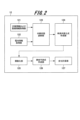
- 2 is a block diagram showing an example of a functional configuration of a calculation unit of a deterioration prediction system for a secondary battery according to an embodiment of the present invention
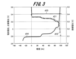
- FIG. 5A to 5C are diagrams showing an example of an internal state diagnosis (battery voltage, positive electrode potential, negative electrode potential) of a secondary battery according to an embodiment of the present invention.
- 5A to 5C are diagrams showing an example of an internal state diagnosis (battery resistance, positive electrode resistance, negative electrode resistance) of a secondary battery according to an embodiment of the present invention.
- FIG. 4 is a diagram showing an example of time series changes in deterioration parameters (active material utilization rate of a positive electrode and active material utilization rate of a negative electrode) of a secondary battery according to an embodiment of the present invention.
- FIG. 1 is a diagram showing an example of time series changes in deterioration parameters of a secondary battery according to an embodiment of the present invention (amount of lithium ion loss associated with film formation on the positive electrode surface, and amount of lithium ion loss associated with film formation on the negative electrode surface).
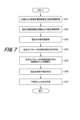
- 5 is a flowchart showing an example of a process for predicting a life span of a secondary battery according to an embodiment of the present invention.
- this embodiment a secondary battery deterioration prediction system and a secondary battery deterioration prediction method according to one embodiment of the present invention (hereinafter referred to as “this embodiment”) will be described with reference to the attached drawings.
- the secondary battery deterioration prediction system 10 includes an input unit 11, a calculation unit 12, and an output unit 13.
- the input unit 11 receives input factors for predicting deterioration of the secondary battery, such as operating conditions of the secondary battery, calculation termination conditions, and output intervals.
- operating conditions of the secondary battery include temperature and load (current).
- calculation termination conditions include a period (e.g., 10 years) and a decrease in battery capacity to 70% or less.
- output intervals include outputting the calculation results every 10 days.
- the calculation unit 12 performs calculation processing relating to the capacity and resistance of the secondary battery until the end condition input to the input unit 11 is satisfied.
- the output unit 13 outputs the calculation results of the capacity and resistance of the secondary battery obtained by the calculation unit 12 as values at output intervals for the period input to the input unit 11 (for example, every 10 days).
- the secondary battery deterioration prediction system 10 shown in FIG. 1 is configured, for example, by a computer. That is, as shown in FIG. 1, the secondary battery deterioration prediction system 10 configured by a computer device includes a CPU (Central Processing Unit) 1, memory 2, storage 3, input device 4, network interface 5, and output unit 6, each of which is connected to a bus.
- a CPU Central Processing Unit
- memory 2 storage
- input device 4 network interface
- output unit 6 output unit
- the CPU 1 is an arithmetic processing unit that reads out from the memory 2 or the storage 3 and executes program code of software that realizes the functions performed by the secondary battery deterioration prediction system 10 .
- the CPU 1 reads out program codes from the memory 2 or the storage 3 and executes arithmetic processing in the work area of the memory 2, whereby various processing function units shown in FIG.
- Storage 3 may be, for example, a large-capacity information storage medium such as a hard disk drive (HDD), solid state drive (SSD), or memory card.
- Storage 3 stores software that realizes the functions of secondary battery deterioration prediction system 10, and data obtained by executing that program.
- the input device 4 includes devices such as a keyboard and a mouse, and performs input processing of various information based on the operations of an operator.
- the network interface 5 may be, for example, a network interface card (NIC), and receives programs from the outside and transmits processing results.
- the output unit 6 uses output devices such as a display and a printer, and performs output processing such as displaying and printing the results of calculations.
- the secondary battery deterioration prediction system 10 configured with the computer shown in FIG. 1 is merely an example, and may be configured with an arithmetic processing device other than a computer.
- some or all of the functions performed by the secondary battery deterioration prediction system 10 may be implemented using an FPGA (Field Programmable Gate Array).
- FPGA Field Programmable Gate Array
- the above-described function may be realized by hardware such as a gate array (Gate Array) or an application specific integrated circuit (ASIC).
- FIG. 2 shows each processing unit constituting the calculation unit 12 of the secondary battery deterioration prediction system 10 of this embodiment.
- the calculation unit 12 includes a positive electrode information and negative electrode information acquisition unit 121, a battery information acquisition unit 122, an internal state diagnosis unit 123, a time-series change equation creation unit 124, a function creation unit 125, a life prediction equation creation unit 126, and a deterioration calculation unit 127.
- Each of these processing units 121 to 127 is configured in the memory 2 shown in FIG. 1 by executing software that realizes the functions performed by the secondary battery deterioration prediction system 10.
- the positive electrode information and negative electrode information acquisition unit 121 and the battery information acquisition unit 122 may acquire information measured using equipment other than the secondary battery deterioration prediction system 10 .
- the calculations performed by the calculation unit 12 include a life prediction calculation for storage deterioration of the secondary battery and a life prediction calculation for operational deterioration of the secondary battery. First, an example of a case where the calculation unit 12 performs a life prediction calculation for storage deterioration of the secondary battery will be described.
- the positive electrode information and negative electrode information acquisition unit 121 performs an acquisition process for acquiring information on the open circuit potential (OCP) and resistance of the positive electrode and negative electrode, which are necessary for diagnosing the internal state of the battery.
- OCP open circuit potential
- An example of a method for acquiring information in the positive electrode information and negative electrode information acquiring unit 121 will be described below.
- a positive electrode single-electrode cell is fabricated using the positive electrode and lithium metal used in the secondary battery to be predicted for life expectancy, and a negative electrode single-electrode cell is fabricated using the negative electrode and lithium metal.
- the Galvanostatic Intermittent Titration Technique GITT is performed on the single-electrode cell to obtain information on the open circuit potential and resistance.
- a single-electrode cell is fully charged, then discharged for 72 seconds at a current equivalent to 1C [A], followed by a 30-minute rest, and this cycle is repeated until the end-of-discharge potential is reached.
- the open-circuit potential at each state of charge (SOC) is the potential 30 minutes after the discharge current is stopped.
- the resistance at each state of charge (SOC) is calculated by dividing the difference between the open-circuit potential before discharge begins and the open-circuit potential after a specified discharge time has elapsed, by the discharge current.
- the battery information acquisition unit 122 performs an acquisition process to acquire information on the secondary battery's open circuit voltage (OCV) and resistance, which are necessary for the internal state diagnosis unit 123 to diagnose the internal state of the battery.
- OCV open circuit voltage
- An example of a method for acquiring information in battery information acquisition section 122 will be described below.
- a storage test is performed on the secondary battery, in which the secondary battery is stored for a certain period of time at a predetermined temperature and state of charge (SOC).
- SOC state of charge
- the battery information acquisition unit 122 periodically stops the test, performs constant current intermittent titration, and acquires information on the open circuit voltage and resistance.
- a single-electrode cell is fully charged, then discharged for 72 seconds at a current equivalent to 1C [A], followed by a 30-minute rest, and this cycle is repeated until the discharge end potential is reached.
- the open circuit potential at each state of charge (SOC) is the voltage 30 minutes after the discharge current is stopped.
- the resistance at each state of charge (SOC) is calculated by dividing the difference between the open circuit voltage before the start of discharge and the open circuit voltage after a specified discharge time has elapsed, by the discharge current.
- the internal state diagnosis unit 123 performs an internal state diagnosis process for diagnosing the internal state of the secondary battery using the information obtained by the positive electrode information and negative electrode information acquisition unit 121 and the battery information acquisition unit 122 . That is, the internal state diagnosis unit 123 diagnoses the internal state of the secondary battery by comparing the open circuit potential and resistance data of the positive and negative electrodes obtained by the positive electrode information and negative electrode information acquisition unit 121 with the open circuit voltage and resistance data of the secondary battery obtained by the battery information acquisition unit 122.
- the internal state can be diagnosed as a number of parameters that are correlated with battery degradation, such as the positive electrode active material utilization rate m p , the negative electrode active material utilization rate m n , the amount of lithium ion loss associated with the formation of a coating on the positive electrode surface ⁇ p , the amount of lithium ion loss associated with the formation of a coating on the negative electrode surface ⁇ n , the battery solution resistance R 0 , the rate of resistance increase of the positive electrode a p , and the rate of resistance increase of the negative electrode a n .
- the positive electrode active material utilization rate m p the negative electrode active material utilization rate m n
- the amount of lithium ion loss associated with the formation of a coating on the positive electrode surface ⁇ p the amount of lithium ion loss associated with the formation of a coating on the negative electrode surface ⁇ n
- the battery solution resistance R 0 the rate of resistance increase of the positive electrode a p
- the utilization rate of the active material of the positive electrode is an index showing the ratio of the active material that can contribute to the battery reaction to the positive electrode active material contained in the electrode.
- the negative electrode active material utilization rate mn is an index showing the ratio of the active material that can contribute to the battery reaction to the negative electrode active material contained in the electrode.
- the amount of lithium ion loss ⁇ p associated with the formation of a film on the positive electrode surface is an index indicating the amount of electricity of lithium ions taken in by the film formed by reaction with the electrolyte on the positive electrode surface.
- the amount of lithium ion loss ⁇ n associated with the formation of a film on the negative electrode surface is an index indicating the amount of electricity of lithium ions taken into the film formed by reaction with the electrolyte on the negative electrode surface.
- the solution resistance R0 of the battery is an index showing the resistance of the battery components when the battery is used.
- the positive electrode resistance increase rate a p is an index showing the resistance increase rate of the positive electrode when the battery is used.
- the negative electrode resistance increase rate a n is an index showing the resistance increase rate of the negative electrode when the battery is used.
- 3 and 4 are diagrams showing examples of fitting results.
- 3 shows the actual open circuit voltage (OCV) value d11 of the secondary battery, its calculated value d12, the positive electrode potential (calculated value) d13, and the negative electrode potential (calculated value) d14.
- OCV open circuit voltage
- the vertical axis on the left side shows the battery voltage and the positive electrode potential [V]
- the vertical axis on the right side shows the negative electrode potential [V].
- the horizontal axis shows the battery capacity [Ah].
- the actual measured value d11 of the open circuit voltage of the secondary battery is plotted as a white circle, and the calculated value d12 is a value calculated based on that.
- FIG. 4 shows the actual resistance value d21 of the secondary battery, its calculated value d22, the positive electrode resistance (calculated value) d23, and the negative electrode resistance (calculated value) d24.
- the vertical axis represents resistance [m ⁇ ]
- the horizontal axis represents battery capacity [Ah].
- the actual measured value d21 of the resistance of the secondary battery is plotted as a white circle, and the calculated value d22 is a value calculated based on this.
- the capacity Qc of the secondary battery can be expressed by the following formula.
- Vc (Q c ) V p (q p ) ⁇ V n (q n )
- the resistance R c at each capacity (each state of charge) of the secondary battery can be expressed by the following equation.
- R c (Q c ) a p /m p ⁇ r p (q p )+a n /m n ⁇ r n (q n )+R 0
- the time-series change equation creation section 124 creates a time-series change equation of the internal parameter obtained by the internal state diagnosis section 123.
- 5 shows an example of a time series change d31 of the negative electrode active material utilization rate mn and a time series change d32 of the positive electrode active material utilization rate mp .
- the horizontal axis of Fig. 5 shows time, and the vertical axis shows the negative electrode active material utilization rate.
- FIG. 6 shows an example of a time series change d41 in the amount of lithium ion loss ⁇ n associated with the formation of a film on the negative electrode surface, and a time series change d42 in the amount of lithium ion loss ⁇ p associated with the formation of a film on the positive electrode surface.
- the horizontal axis indicates time
- the vertical axis indicates the amount of lithium ion loss associated with the formation of a coating on the negative electrode surface.
- the time-series change equation creating section 124 creates a time-series change equation that indicates the time-series change of the internal parameter obtained by the internal state diagnosis section 123 .
- the function generating unit 125 generates a function of the operating conditions using the coefficients of the time series change equation of each deterioration parameter obtained by the time series change equation generating unit 124 .
- the dependency of the coefficients m 1 and m 1 ' on the operating conditions is expressed as a function.
- ⁇ ⁇ + ⁇ Temperature+ ⁇ SOC
- m 1 (m 1' ) ⁇ ⁇ ( ⁇ ⁇ temperature) + ( ⁇ ⁇ SOC) etc.
- ⁇ , ⁇ , and ⁇ are coefficients whose values are determined by fitting.
- the calculation unit 12 calculates the storage deterioration of a secondary battery.
- the positive electrode information and negative electrode information acquisition unit 121 acquires information on the open circuit potential and resistance of the positive electrode and the negative electrode, which are necessary for diagnosing the internal state of the battery.
- the acquisition method here is the same as that for calculating the storage deterioration.
- the battery information acquisition unit 122 acquires information on the secondary battery's open circuit voltage and resistance, which are necessary for diagnosing the internal state of the battery.
- the battery information acquisition unit 122 first performs a cycle test on the secondary battery in which charging and discharging are repeated at a predetermined temperature and within a predetermined range of the state of charge (SOC) at a constant current.
- SOC state of charge
- the battery information acquisition unit 122 periodically stops the test, performs constant current intermittent titration (GITT), and acquires information on the open circuit voltage and resistance.
- GITT constant current intermittent titration
- a single-electrode cell is fully charged, then discharged for 72 seconds at a current equivalent to 1C [A], followed by a 30-minute rest, and this cycle is repeated until the discharge end potential is reached.
- the open circuit potential at each state of charge (SOC) is the voltage 30 minutes after the discharge current is stopped.
- the resistance at each state of charge (SOC) is calculated by dividing the difference between the open circuit voltage before discharge begins and the open circuit voltage after a specified discharge time has elapsed, by the discharge current.
- the internal state diagnosis unit 123 uses the information obtained by the positive electrode information and negative electrode information acquisition unit 121 and the battery information acquisition unit 122 to diagnose the internal state of the secondary battery. That is, the internal state diagnosis unit 123 diagnoses the internal state of the secondary battery by comparing the open circuit potential and resistance data of the positive and negative electrodes obtained by the positive electrode information and negative electrode information acquisition unit 121 with the open circuit voltage and resistance data of the secondary battery obtained by the battery information acquisition unit 122.
- the internal state may be diagnosed based on the following parameters: the active material utilization rate m p of the positive electrode, the active material utilization rate m n of the negative electrode, the amount of lithium ion loss associated with the formation of a coating on the positive electrode surface ⁇ p , the amount of lithium ion loss associated with the formation of a coating on the negative electrode surface ⁇ n , the solution resistance R 0 of the battery, the rate of resistance increase of the positive electrode a p , and the rate of resistance increase of the negative electrode a n , all of which are correlated with battery degradation.
- the internal state diagnosis unit 123 uses these seven as variable parameters, and fits the data on the open circuit potential and resistance of the positive and negative electrodes obtained by the positive electrode information and negative electrode information acquisition unit 121 to the data on the open circuit voltage and resistance of the secondary battery obtained by the battery information acquisition unit 122.
- the fitting method is the same as that used to calculate the storage deterioration of the secondary battery.
- the time-series change equation creation section 124 creates a time-series change equation of the internal parameter obtained by the internal state diagnosis section 123 .
- the time series change equation creation unit 124 calculates the change in the internal parameters of only the operating load by subtracting the change in parameters due to the storage load calculated using a function of each parameter of the storage load obtained when calculating the storage deterioration.
- the time series change equation creation unit 124 plots the time series changes of each parameter and draws an approximation curve.
- the shape of the approximation curve can be arbitrarily set for each parameter, such as a linear curve, a quadratic curve, a root system equation, or a power system equation.
- the function generating unit 125 generates a function of the operating conditions from the coefficients of the time series change equation of each of the obtained deterioration parameters.
- the dependency of the coefficients m 1 and m 1 ' on the operating conditions is expressed as a function.
- m 1 (m 1' ) ⁇ + ⁇ ⁇ temperature + ⁇ ⁇ center SOC + ⁇ ⁇ SOC range + ⁇ ⁇ current
- m 1 (m 1' ) ⁇ ⁇ ( ⁇ ⁇ temperature) ⁇ ( ⁇ ⁇ center SOC) ⁇ ( ⁇ ⁇ SOC range) ⁇ ( ⁇ ⁇ current) etc.
- ⁇ , ⁇ , ⁇ , and ⁇ are coefficients. The values of these coefficients ⁇ , ⁇ , ⁇ , ⁇ , and ⁇ are determined by fitting.
- the life prediction equation creation unit 126 inputs the operating conditions of the secondary battery whose life is to be predicted into the function created by the function creation unit 125 when calculating the storage deterioration of the secondary battery, and into the function created by the function creation unit 125 when calculating the operational deterioration of the secondary battery, to create a life prediction equation for the secondary battery whose life is to be predicted.
- the deterioration calculation unit 127 calculates internal deterioration parameters based on the life prediction equation created by the life prediction equation creation unit 126 .
- the life prediction equation creation unit 126 inputs internal deterioration parameters into the following equation to create a life prediction equation that calculates capacitance Qc and resistance Rc .
- R c a p /m p ⁇ r p +a n /m n ⁇ r n +R 0
- the deterioration calculation unit 127 divides the result of the life prediction formula obtained by the life prediction formula creation unit 126 by the initial capacity Q ini and initial resistance R ini of the secondary battery to calculate the rate of change of the capacity and resistance.
- the deterioration calculation unit 127 can obtain the time series changes in the rate of change of the capacitance and resistance as shown in Figs. 5 and 6.
- FIG. 7 is a flow chart showing the calculation process of the storage deterioration and the operational deterioration of the secondary battery in the calculation unit 12 described above.
- the positive electrode information and negative electrode information acquisition unit 121 acquires information on the open circuit potential and resistance of the positive electrode and negative electrode, which are necessary for diagnosing the internal state of the battery (step S11).
- the battery information acquisition unit 122 acquires information on the secondary battery's open circuit voltage and resistance, which are necessary for diagnosing the internal state of the battery (step S12).
- the internal state diagnosis unit 123 diagnoses the internal state of the secondary battery using the information on the open circuit potential and resistance of the positive and negative electrodes obtained by the positive electrode information and negative electrode information acquisition unit 121 in step S11, and the information on the secondary battery open circuit voltage and resistance obtained by the battery information acquisition unit 122 in step S12 (step S13).
- the time-series change equation creation unit 124 creates a time-series change equation for storage deterioration of the secondary battery and a time-series change equation for operational deterioration of the secondary battery (step S14).
- the function generator 125 generates a function based on the operating conditions of the time series change equation of the storage deterioration of the secondary battery, and generates a function based on the operating conditions of the time series change equation of the operational deterioration of the secondary battery (step S15).
- the life prediction formula generation unit 126 performs a life prediction formula generation process in which the operating conditions of the secondary battery whose life is to be predicted are input into the function generated when calculating the storage deterioration of the secondary battery and the function generated when calculating the operational deterioration of the secondary battery, to generate a life prediction formula for the secondary battery whose life is to be predicted (step S16).
- the deterioration calculation unit 127 calculates the internal deterioration parameters based on the life prediction formula created by the life prediction formula creation unit 126 (step S17).
- the deterioration calculation unit 127 may, for example, obtain the operating conditions of the secondary battery and calculate the deterioration state.
- the calculated internal deterioration parameters are output, for example, as a graph of the deterioration state as shown in FIG. 5 or FIG. 6, or a table of the deterioration state.
- the secondary battery degradation prediction system 10 of this example can diagnose the internal state of the secondary battery with high accuracy, even in a secondary battery system in which the change in voltage relative to the change in the charging state is small, and can predict the lifespan with high accuracy based on the obtained diagnosis results.
- the internal state diagnosis unit 123 diagnoses the deterioration state of the positive and negative electrodes using a group of relationships between the state of charge and open circuit potential specific to the positive electrode active material of the secondary battery, a group of relationships between the state of charge and internal resistance, a group of relationships between the state of charge and open circuit potential specific to the negative electrode active material of the secondary battery, and a group of relationships between the state of charge and internal resistance.
- the internal state diagnosis unit 123 can be said to contribute to the high accuracy of life prediction.
- the secondary battery deterioration prediction system 10 of this example is provided with a time series change equation creation unit 124 that creates a time series change equation for the state diagnosed by the internal state diagnosis unit 123, and the life prediction equation creation unit 126 creates a life prediction equation based on the time series change equation created by the time series change equation creation unit 124. This makes it possible to make an appropriate life prediction that reflects the time series changes.
- the internal state diagnosis unit 123 extracts parameters such as the active material utilization rate of the positive electrode, the active material utilization rate of the negative electrode, the amount of lithium ion loss associated with the formation of a coating on the positive electrode surface, the amount of lithium ion loss associated with the formation of a coating on the negative electrode surface, the solution resistance of the battery, the resistance increase rate of the positive electrode, and the resistance increase rate of the negative electrode to diagnose the internal state.
- the internal state diagnosis unit 123 contributes to improving the accuracy of life prediction. Note that in the above-mentioned embodiment, extracting all of these parameters and using them to diagnose the internal state is just one example, and a part of these parameters (at least one) may be extracted and used to diagnose the internal state.
- time series change equation creation unit 124 creates a battery life prediction equation based on the time series changes of the parameters extracted by the internal state diagnosis unit 123. In this respect, the time series change equation creation unit 124 contributes to improving the accuracy of life prediction.
- the internal state diagnosis unit 123 diagnoses the deterioration of the secondary battery due to storage load and deterioration due to operation load
- the life prediction formula creation unit 126 creates a battery life prediction formula by combining the deterioration due to storage load and the deterioration due to operation load, making it possible to make an appropriate life prediction that reflects the time-series changes due to each type of deterioration.
- the degradation calculation unit 127 acquires the operating conditions of the secondary battery, calculates and outputs the time series changes in the capacity and resistance of the secondary battery, making it possible to make an appropriate life prediction based on the operating conditions of the secondary battery.
- the life prediction formula creation unit 126 calculates the time series changes in the deterioration states of the positive and negative electrodes for storage deterioration, which is when no load is applied to the secondary battery, and the time series changes in the deterioration states of the positive and negative electrodes for operational deterioration, which is when a load is applied to the secondary battery, and creates a life prediction formula.
- the life prediction formula creation unit 126 may create a life prediction formula based on time series changes in the deterioration state of the positive and negative electrodes regarding operational deterioration when a load is applied to the secondary battery.
- the secondary battery deterioration prediction system 10 is configured as one computer, but a similar deterioration prediction system may be configured as multiple computers.
- some of the data such as data measuring the positive and negative electrodes of the secondary battery, may be stored in a server connected to the secondary battery deterioration prediction system 10 via a network, and the secondary battery deterioration prediction system 10 may exchange information with the server to perform similar processing.
- some of the components provided in the calculation unit 12 shown in FIG. 2 may be placed in a separate computer and processed by the separate computer.
- the programs that realize each processing function may be stored in non-volatile storage or memory within the computer device, or may be stored in an external memory, IC card, SD card, optical disk, or other recording medium and transferred.
Landscapes
- Physics & Mathematics (AREA)
- General Physics & Mathematics (AREA)
- Engineering & Computer Science (AREA)
- Manufacturing & Machinery (AREA)
- Chemical & Material Sciences (AREA)
- Chemical Kinetics & Catalysis (AREA)
- Electrochemistry (AREA)
- General Chemical & Material Sciences (AREA)
- Secondary Cells (AREA)
- Tests Of Electric Status Of Batteries (AREA)
- Charge And Discharge Circuits For Batteries Or The Like (AREA)
Abstract
Description
そこで、所定の期間、稼働させることを目的に電力貯蔵システムを導入する場合、二次電池の劣化を見越して設計する必要がある。しかし、二次電池の劣化予測の精度が低いと安全マージンを多く含んだ設計とする必要があるため、過剰な電池の搭載により、電力貯蔵システムが高コスト化してしまう。そこで、高精度に電池の寿命を予測する劣化予測システムが求められている。
しかしながら、充電状態の変化による電圧の変化が小さい電極活物質系であるLiFePO4正極、Li4Ti5O12負極などから構成される電池系の診断をするのは困難であった。
本願は、上記課題を解決する手段を複数含んでいるが、その一例を挙げるならば、二次電池の劣化予測システムとして、二次電池の各稼働条件における、二次電池の充電状態と開回路電圧との関係、および電池の充電状態と内部抵抗の関係を取得する取得部と、取得部が取得した関係に基づいて、各稼働条件における二次電池の正極と負極の劣化状態を診断する内部状態診断部と、内部状態診断部で得られた劣化状態の時系列変化に基づいて二次電池の寿命予測を行うための寿命予測式を作成する寿命予測式作成部と、寿命予測式作成部が作成した寿命予測式に基づいて二次電池の劣化を計算する劣化計算部と、を備える。
ここで、寿命予測式作成部は、二次電池に負荷をかけた場合の正極および負極の劣化状態の時系列変化に基づいて寿命予測式を作成するようにした。
上記した以外の課題、構成および効果は、以下の実施形態の説明により明らかにされる。
入力部11には、二次電池の劣化予測を行うための入力因子として、二次電池の稼働条件と、計算の終了条件と、出力間隔などが入力される。二次電池の稼働条件としては、例えば温度、負荷(電流)などがある。計算の終了条件としては、期間(10年間など)、電池容量が70%以下に低下、などがある。出力間隔としては、10日毎に計算結果を出力するなどがある。
これらの入力因子は、例えば劣化予測を行う操作者によって入力される。
出力部13は、計算部12での計算で得られた二次電池の容量および抵抗の計算結果を、入力部11に入力した期間(10日毎など)の出力間隔の値として出力する。
CPU1がメモリ2またはストレージ3からプログラムコードを読み出して、メモリ2のワークエリアで演算処理を実行することで、後述する図2に示す様々な処理機能部がメモリ2に構成される。
ネットワークインタフェース5には、例えば、NIC(Network Interface Card)などが用いられ、外部からのプログラムなどの受信や、処理結果の送信などが行われる。
出力部6には、ディスプレイやプリンタなどの出力機器が使用され、計算結果の表示やプリントなどの出力処理が行われる。
Gate Array)やASIC(Application Specific Integrated Circuit)などのハードウェアによって実現してもよい。
計算部12は、正極情報及び負極情報取得部121、電池情報取得部122、内部状態診断部123、時系列変化式作成部124、関数化部125、寿命予測式作成部126、および劣化計算部127を備える。これらの各処理部121~127は、二次電池の劣化予測システム10が行う機能を実現するソフトウェアを実行することにより、図1に示すメモリ2に構成される。
計算部12が行う計算には、二次電池の保存劣化の寿命予測計算と、二次電池の稼働劣化の寿命予測計算が含まれる。最初に、計算部12が二次電池の保存劣化の寿命予測計算を行う場合の例について説明する。
正極情報及び負極情報取得部121における情報の取得方法の一例を、以下に説明する。
まず、寿命予測対象の二次電池に使用されている正極とリチウム金属を用いた正極単極セル、および負極とリチウム金属を用いた負極単極セルを作製する。続いて単極セルに対し、定電流間欠滴定法(GITT:Galvanostatic Intermittent Titration Technique)を実施し、開回路電位と抵抗の情報を取得する。
電池情報取得部122における情報の取得方法の一例を、以下に説明する。
まず二次電池に対し、所定の温度および充電率(SOC)で一定期間保存する保存試験を実施する。
電池情報取得部122は、保存試験を実施する際に、定期的に試験を停止し、定電流間欠滴定法を実施し、開回路電圧と抵抗の情報を取得する。
すなわち、内部状態診断部123は、正極情報及び負極情報取得部121で得られた正極および負極の開回路電位および抵抗のデータを、電池情報取得部122で得られた二次電池の開回路電圧および抵抗のデータと比較することで、二次電池の内部状態を診断する。
内部状態の診断対象としては、電池劣化と相関のある、正極の活物質利用率mp、負極の活物質利用率mn、正極表面の被膜形成に伴うリチウムイオン損失量δp、負極表面の被膜形成に伴うリチウムイオン損失量δn、電池の溶液抵抗R0、正極の抵抗上昇率ap、および負極の抵抗上昇率anなどが挙げられる。
負極の活物質利用率mnは、電極中に含まれる負極活物質のうち、電池反応に寄与できる活物質の比率を示す指標である。
正極表面の被膜形成に伴うリチウムイオン損失量δpは、正極表面における電解液との反応により生成する被膜に取り込まれたリチウムイオンの電気量を示す指標である。
電池の溶液抵抗R0は、電池を利用した際の電池部材の抵抗を示す指標である。
正極の抵抗上昇率apは、電池を利用した際の正極の抵抗上昇率を示す指標である。
負極の抵抗上昇率anは、電池を利用した際の負極の抵抗上昇率を示す指標である。
図3は、二次電池の開回路電圧(OCV)の実測値d11、その計算値d12、正極電位(計算値)d13、負極電位(計算値)d14を示す。図3において、左側の縦軸は電池電圧および正極電位[V]を示し、右側の縦軸は負極電位[V]を示す。横軸は電池容量[Ah]である。
図3において、二次電池の開回路電圧の実測値d11は白丸でプロットした箇所であり、計算値d12はそれに基づいて計算した値である。
図4において、二次電池の抵抗の実測値d21は白丸でプロットした箇所であり、計算値d22はそれに基づいて計算した値である。
Qc=mp×qp-δp=mn×qn-δn
Vc(Qc)=Vp(qp)-Vn(qn)
Rc(Qc)=ap/mp×rp(qp)+an/mn×rn(qn)+R0
図5は、負極の活物質利用率mnの時系列変化d31と、正極の活物質利用率mpの時系列変化d32の一例を示す。図5の横軸は時間、縦軸は負極の活物質利用率を示す。
図6の横軸は時間、縦軸は負極表面の被膜形成に伴うリチウムイオン損失量を示す。
このようにして、時系列変化式作成部124は、内部状態診断部123で得られた内部パラメータの時系列変化を示す時系列変化式を作成する。
例えば、時系列変化式作成部124は、図5に示す負極の活物質利用率mnの時系列変化式として、
mn=m0-m1×t
を作成する。
また、時系列変化式作成部124は、図6に示す負極表面の被膜形成に伴うリチウムイオン損失量δnの時系列変化式として、
δn=m0′+m1′×(t)0.5
を作成する。
ここで、関数化の一例を説明すると、関数化部125は、図5示した、負極の活物質利用率mn、負極表面の被膜形成に伴うリチウムイオン損失量δnの時系列変化式
mn=m0-m1×t
δn=m0′+m1′×(t)0.5
に対し係数m1、m1’の稼働条件の依存性を関数化する。
m1(m1′)=α+β×温度+γ×SOC
m1(m1′)=α×(β×温度)+(γ×SOC)
などが挙げられる。
ここで、α、β、γは係数である。これらの係数α、β、γの値は、フィッティングにより決定される。
次に、計算部12が二次電池の稼働劣化を計算する場合について説明する。
まず、正極情報及び負極情報取得部121は、電池の内部状態を診断するために必要な、正極および負極の開回路電位と抵抗の情報を取得する。ここでの取得方法は、保存劣化を計算する場合と同様である。
ここでは、電池情報取得部122は、まず二次電池に対し、所定の温度において、所定の充電率(SOC)の範囲で一定電流での充放電を繰り返すサイクル試験を実施する。
そして、電池情報取得部122は、サイクル試験を実施する際には、定期的に試験を停止して、定電流間欠滴定法(GITT)を実施し、開回路電圧と抵抗の情報を取得する。
すなわち、内部状態診断部123は、正極情報及び負極情報取得部121で得られた正極および負極の開回路電位および抵抗のデータを、電池情報取得部122で得られた二次電池の開回路電圧および抵抗のデータと比較することで、二次電池の内部状態を診断する。
なお、内部状態の診断対象としては、電池劣化と相関のある、正極の活物質利用率mp、負極の活物質利用率mn、正極表面の被膜形成に伴うリチウムイオン損失量δp、負極表面の被膜形成に伴うリチウムイオン損失量δn、電池の溶液抵抗R0、正極の抵抗上昇率ap、負極の抵抗上昇率anなどが挙げられる。
ここで、稼働負荷の内部パラメータは、保存負荷の影響を含んでいるため、時系列変化式作成部124は、保存劣化の計算時に得た保存負荷の各パラメータの関数により計算される保存負荷によるパラメータの変化を差し引いて、稼働負荷のみの内部パラメータの変化を計算する。
関数化の一例を示すと、関数化部125は、負極の活物質利用率mn、負極表面の被膜形成に伴うリチウムイオン損失量δnの時系列変化式
mn=m0-m1×t
δn=m0′+m1′×(t)0.5
に対し係数m1、m1′の稼働条件の依存性を関数化する。
m1(m1′)=α+β×温度+γ×中心SOC+ε×SOC範囲+ζ×電流
m1(m1′)=α×(β×温度)×(γ×中心SOC)×(ε×SOC範囲)×(ζ×電流)
などが挙げられる。
ここで、α、β、γ、ε、ζは係数である。これらの係数α、β、γ、ε、ζの値はフィッティングにより決定される。
劣化計算部127は、寿命予測式作成部126で作成した寿命予測式に基づいて、内部劣化パラメータを計算する。
Qc=mp×qp―δp=mn×qn―δn
Rc=ap/mp×rp+an/mn×rn+R0
これにより、劣化計算部127は、図5および図6に示すような容量および抵抗の変化率の時系列変化を得ることができる。具体的には、
容量の変化率 SOHQ=Qc/Qini×100
抵抗の変化率 SOHR=Rc/Rini×100
として、示すことができる。
まず、正極情報及び負極情報取得部121は、電池の内部状態を診断するために必要な、正極および負極の開回路電位と抵抗の情報を取得する(ステップS11)。
また、電池情報取得部122は、電池の内部状態を診断するために必要な、二次電池開回路電圧と抵抗の情報を取得する(ステップS12)。
この内部状態を診断に基づいて、時系列変化式作成部124は、二次電池の保存劣化の時系列変化式と、二次電池の稼働劣化の時系列変化式を作成する(ステップS14)。
関数化部125で関数化が行われると、寿命予測式作成部126は、二次電池の保存劣化の計算時に作成した関数と、二次電池の稼働劣化の計算時に作成した関数に、寿命予測したい二次電池の稼働条件を入力して、寿命予測したい二次電池の寿命予測式を作成する寿命予測式作成処理を行う(ステップS16)。
これに対して、寿命予測式作成部126は、二次電池に負荷をかけた場合である稼働劣化についての、正極および負極の劣化状態の時系列変化に基づいて寿命予測式を作成するようにしてもよい。但し、寿命予測する精度としては、二次電池に負荷をかけていない場合の時系列変化と、二次電池に負荷をかけた場合の時系列変化から寿命予測式を作成する方がよい。
また、図7に示すフローチャートに示す処理の流れについても一例であり、処理結果が同じであれば、一部の処理順序の変更や、複数の処理の同時実行を行うようにしてもよい。
Claims (9)
- 二次電池の各稼働条件における、当該二次電池の充電状態と開回路電圧との関係、および電池の充電状態と内部抵抗の関係を取得する取得部と、
前記取得部が取得した関係に基づいて、各稼働条件における前記二次電池の正極と負極の劣化状態を診断する内部状態診断部と、
前記内部状態診断部で得られた劣化状態の時系列変化に基づいて前記二次電池の寿命予測を行うための寿命予測式を作成する寿命予測式作成部と、
前記寿命予測式作成部が作成した寿命予測式に基づいて前記二次電池の劣化を計算する劣化計算部と、を備え、
前記寿命予測式作成部は、前記二次電池に負荷をかけた場合の正極および負極の劣化状態の時系列変化に基づいて寿命予測式を作成する
二次電池の劣化予測システム。 - 前記寿命予測式作成部は、さらに、前記二次電池に負荷をかけていない場合の、正極および負極の劣化状態の時系列変化に基づいて寿命予測式を作成する
請求項1に記載の二次電池の劣化予測システム。 - 前記内部状態診断部は、
前記二次電池の正極活物質に固有の充電状態と開回路電位との関係群と、充電状態と内部抵抗の関係群と、
前記二次電池の負極活物質に固有の充電状態と開回路電位との関係群と、充電状態と内部抵抗の関係群と、
を用いて正極と負極の劣化状態を診断する
請求項2に記載の二次電池の劣化予測システム。 - 前記内部状態診断部が診断した状態の時系列変化式を作成する時系列変化式作成部を備え、
前記時系列変化式作成部が作成した時系列変化式に基づいて、前記寿命予測式作成部が寿命予測式を作成する
請求項3に記載の二次電池の劣化予測システム。 - さらに、前記内部状態診断部は、
正極と負極の劣化状態を診断する際に、
正極の活物質利用率、負極の活物質利用率、正極表面の被膜形成に伴うリチウムイオン損失量、負極表面の被膜形成に伴うリチウムイオン損失量、電池の溶液抵抗、正極の抵抗上昇率、負極の抵抗上昇率のうち少なくとも一つのパラメータを抽出する
請求項4に記載の二次電池の劣化予測システム。 - 前記時系列変化式作成部は、前記内部状態診断部が抽出した抽出したパラメータの時系列変化に基づいて時系列変化式を作成する
請求項5に記載の二次電池の劣化予測システム。 - さらに、前記内部状態診断部は、前記二次電池の保存負荷による劣化と、稼働負荷による劣化を診断し、
前記寿命予測式作成部は、保存負荷による劣化と、稼働負荷による劣化とを組合せて電池寿命の予測式を作成する
請求項2に記載の二次電池の劣化予測システム。 - 前記劣化計算部は、前記二次電池の稼働条件に基づいて、前記二次電池の容量および抵抗の時系列変化を計算して出力する
請求項2に記載の二次電池の劣化予測システム。 - 二次電池の各稼働条件における、当該二次電池の充電状態と開回路電圧との関係、および電池の充電状態と内部抵抗の関係を取得する取得処理と、
前記取得処理により取得した関係に基づいて、各稼働条件における前記二次電池の正極と負極の劣化状態を診断する内部状態診断処理と、
前記内部状態診断処理により得られた劣化状態の時系列変化に基づいて前記二次電池の寿命予測を行うための寿命予測式を作成する寿命予測式作成処理と、
前記寿命予測式作成処理により作成した寿命予測式に基づいて前記二次電池の劣化を計算する劣化計算処理と、を含み、
前記寿命予測式作成処理で作成する寿命予測式は、前記二次電池に負荷をかけた場合の正極および負極の劣化状態の時系列変化に基づいて作成したものである
二次電池の劣化予測方法。
Priority Applications (1)
| Application Number | Priority Date | Filing Date | Title |
|---|---|---|---|
| EP24818981.3A EP4726414A1 (en) | 2023-06-08 | 2024-03-05 | Secondary battery deterioration prediction system and secondary battery deterioration prediction method |
Applications Claiming Priority (2)
| Application Number | Priority Date | Filing Date | Title |
|---|---|---|---|
| JP2023094679A JP2024176252A (ja) | 2023-06-08 | 2023-06-08 | 二次電池の劣化予測システムおよび二次電池の劣化予測方法 |
| JP2023-094679 | 2023-06-08 |
Publications (1)
| Publication Number | Publication Date |
|---|---|
| WO2024252742A1 true WO2024252742A1 (ja) | 2024-12-12 |
Family
ID=93795717
Family Applications (1)
| Application Number | Title | Priority Date | Filing Date |
|---|---|---|---|
| PCT/JP2024/008352 Ceased WO2024252742A1 (ja) | 2023-06-08 | 2024-03-05 | 二次電池の劣化予測システムおよび二次電池の劣化予測方法 |
Country Status (3)
| Country | Link |
|---|---|
| EP (1) | EP4726414A1 (ja) |
| JP (1) | JP2024176252A (ja) |
| WO (1) | WO2024252742A1 (ja) |
Citations (5)
| Publication number | Priority date | Publication date | Assignee | Title |
|---|---|---|---|---|
| JP2009080093A (ja) | 2007-09-07 | 2009-04-16 | Hitachi Vehicle Energy Ltd | 二次電池の内部情報検知方法及び装置 |
| JP2016082728A (ja) * | 2014-10-17 | 2016-05-16 | 株式会社日立製作所 | 二次電池の制御方法 |
| WO2018003210A1 (ja) * | 2016-06-28 | 2018-01-04 | 株式会社日立製作所 | 二次電池制御システム、二次電池制御方法 |
| JP2021039939A (ja) * | 2019-08-30 | 2021-03-11 | 株式会社Gsユアサ | 推定装置及び推定方法 |
| JP2023077830A (ja) * | 2021-11-25 | 2023-06-06 | 株式会社日立製作所 | 二次電池の状態診断方法および状態診断装置 |
-
2023
- 2023-06-08 JP JP2023094679A patent/JP2024176252A/ja active Pending
-
2024
- 2024-03-05 EP EP24818981.3A patent/EP4726414A1/en active Pending
- 2024-03-05 WO PCT/JP2024/008352 patent/WO2024252742A1/ja not_active Ceased
Patent Citations (5)
| Publication number | Priority date | Publication date | Assignee | Title |
|---|---|---|---|---|
| JP2009080093A (ja) | 2007-09-07 | 2009-04-16 | Hitachi Vehicle Energy Ltd | 二次電池の内部情報検知方法及び装置 |
| JP2016082728A (ja) * | 2014-10-17 | 2016-05-16 | 株式会社日立製作所 | 二次電池の制御方法 |
| WO2018003210A1 (ja) * | 2016-06-28 | 2018-01-04 | 株式会社日立製作所 | 二次電池制御システム、二次電池制御方法 |
| JP2021039939A (ja) * | 2019-08-30 | 2021-03-11 | 株式会社Gsユアサ | 推定装置及び推定方法 |
| JP2023077830A (ja) * | 2021-11-25 | 2023-06-06 | 株式会社日立製作所 | 二次電池の状態診断方法および状態診断装置 |
Also Published As
| Publication number | Publication date |
|---|---|
| JP2024176252A (ja) | 2024-12-19 |
| EP4726414A1 (en) | 2026-04-15 |
Similar Documents
| Publication | Publication Date | Title |
|---|---|---|
| JP6918433B1 (ja) | 劣化度診断装置 | |
| JP6300945B2 (ja) | バッテリの複数のセルを制御する装置及び方法 | |
| JP5936711B2 (ja) | 蓄電デバイスの寿命予測装置及び蓄電デバイスの寿命予測方法 | |
| WO2019202752A1 (ja) | 蓄電池診断装置および蓄電池診断方法、並びに蓄電池制御システム | |
| EP2871742A1 (en) | Strategic modeling for economic optimization of grid-tied energy assets | |
| Peng et al. | Data-driven battery capacity estimation based on partial discharging capacity curve for lithium-ion batteries | |
| Li et al. | Modeling and SOC estimation of lithium iron phosphate battery considering capacity loss | |
| US12000901B2 (en) | Battery state estimation based on multiple rates of hysteresis transit | |
| CN116559689B (zh) | 使用过电位的等效恒定电流模型的电池状态估计 | |
| WO2023022224A1 (ja) | 二次電池の容量保持率推定方法及び二次電池の容量保持率推定プログラム並びに二次電池の容量保持率推定装置 | |
| Kazhamiaka et al. | Tractable lithium-ion storage models for optimizing energy systems | |
| JP7574471B2 (ja) | 二次電池の診断方法、充放電制御方法、診断装置、管理システム、及び、診断プログラム | |
| JP7547654B2 (ja) | 電池の診断方法、電池の診断装置、電池の管理システム、及び、電池の診断プログラム | |
| US20240230782A1 (en) | Diagnosis method and diagnosis apparatus of power storage system, power storage system, and non-transitory storage medium | |
| Eltamaly | An accurate piecewise aging model for Li-ion batteries in hybrid renewable energy system applications | |
| WO2022049804A1 (en) | Determination device relating to plurality of batteries, electricity storage system, determination method and determination program | |
| CN117421936A (zh) | 一种锂离子电池储能系统运行可靠性评估方法及装置 | |
| CN121142329A (zh) | 一种用于储能系统的soc动态校准方法、系统及存储介质 | |
| WO2024252742A1 (ja) | 二次電池の劣化予測システムおよび二次電池の劣化予測方法 | |
| Na et al. | Machine learning approaches to estimate the health state of next-generation energy storage | |
| CN119861294A (zh) | 一种电池soc估算及校准的方法、终端及多电池储能系统 | |
| WO2025135077A1 (ja) | 二次電池の劣化予測システム、及び、二次電池の劣化予測方法 | |
| Vetter et al. | The Use of Batteries in Storing Electricity | |
| CN117665576A (zh) | 一种电池荷电状态获得方法以及装置 | |
| CN119270115B (zh) | 一种基于多阻抗测量的现场电池健康评估方法 |
Legal Events
| Date | Code | Title | Description |
|---|---|---|---|
| 121 | Ep: the epo has been informed by wipo that ep was designated in this application |
Ref document number: 24818981 Country of ref document: EP Kind code of ref document: A1 |
|
| WWE | Wipo information: entry into national phase |
Ref document number: 2024818981 Country of ref document: EP |
|
| NENP | Non-entry into the national phase |
Ref country code: DE |
|
| ENP | Entry into the national phase |
Ref document number: 2024818981 Country of ref document: EP Effective date: 20260108 |
|
| ENP | Entry into the national phase |
Ref document number: 2024818981 Country of ref document: EP Effective date: 20260108 |
|
| ENP | Entry into the national phase |
Ref document number: 2024818981 Country of ref document: EP Effective date: 20260108 |
|
| ENP | Entry into the national phase |
Ref document number: 2024818981 Country of ref document: EP Effective date: 20260108 |
|
| ENP | Entry into the national phase |
Ref document number: 2024818981 Country of ref document: EP Effective date: 20260108 |
|
| WWP | Wipo information: published in national office |
Ref document number: 2024818981 Country of ref document: EP |