WO2024252721A1 - 生体情報測定装置 - Google Patents
生体情報測定装置 Download PDFInfo
- Publication number
- WO2024252721A1 WO2024252721A1 PCT/JP2024/002938 JP2024002938W WO2024252721A1 WO 2024252721 A1 WO2024252721 A1 WO 2024252721A1 JP 2024002938 W JP2024002938 W JP 2024002938W WO 2024252721 A1 WO2024252721 A1 WO 2024252721A1
- Authority
- WO
- WIPO (PCT)
- Prior art keywords
- arm
- cuff
- biological information
- sensor
- blood pressure
- Prior art date
- Legal status (The legal status is an assumption and is not a legal conclusion. Google has not performed a legal analysis and makes no representation as to the accuracy of the status listed.)
- Ceased
Links
Images




Classifications
-
- A—HUMAN NECESSITIES
- A61—MEDICAL OR VETERINARY SCIENCE; HYGIENE
- A61B—DIAGNOSIS; SURGERY; IDENTIFICATION
- A61B5/00—Measuring for diagnostic purposes; Identification of persons
- A61B5/02—Detecting, measuring or recording for evaluating the cardiovascular system, e.g. pulse, heart rate, blood pressure or blood flow
- A61B5/021—Measuring pressure in heart or blood vessels
- A61B5/02141—Details of apparatus construction, e.g. pump units or housings therefor, cuff pressurising systems, arrangements of fluid conduits or circuits
-
- A—HUMAN NECESSITIES
- A61—MEDICAL OR VETERINARY SCIENCE; HYGIENE
- A61B—DIAGNOSIS; SURGERY; IDENTIFICATION
- A61B5/00—Measuring for diagnostic purposes; Identification of persons
- A61B5/24—Detecting, measuring or recording bioelectric or biomagnetic signals of the body or parts thereof
- A61B5/25—Bioelectric electrodes therefor
- A61B5/251—Means for maintaining electrode contact with the body
- A61B5/256—Wearable electrodes, e.g. having straps or bands
-
- A—HUMAN NECESSITIES
- A61—MEDICAL OR VETERINARY SCIENCE; HYGIENE
- A61B—DIAGNOSIS; SURGERY; IDENTIFICATION
- A61B5/00—Measuring for diagnostic purposes; Identification of persons
- A61B5/02—Detecting, measuring or recording for evaluating the cardiovascular system, e.g. pulse, heart rate, blood pressure or blood flow
- A61B5/0205—Simultaneously evaluating both cardiovascular conditions and different types of body conditions, e.g. heart and respiratory condition
-
- A—HUMAN NECESSITIES
- A61—MEDICAL OR VETERINARY SCIENCE; HYGIENE
- A61B—DIAGNOSIS; SURGERY; IDENTIFICATION
- A61B5/00—Measuring for diagnostic purposes; Identification of persons
- A61B5/02—Detecting, measuring or recording for evaluating the cardiovascular system, e.g. pulse, heart rate, blood pressure or blood flow
- A61B5/021—Measuring pressure in heart or blood vessels
- A61B5/022—Measuring pressure in heart or blood vessels by applying pressure to close blood vessels, e.g. against the skin; Ophthalmodynamometers
- A61B5/02233—Occluders specially adapted therefor
-
- A—HUMAN NECESSITIES
- A61—MEDICAL OR VETERINARY SCIENCE; HYGIENE
- A61B—DIAGNOSIS; SURGERY; IDENTIFICATION
- A61B5/00—Measuring for diagnostic purposes; Identification of persons
- A61B5/02—Detecting, measuring or recording for evaluating the cardiovascular system, e.g. pulse, heart rate, blood pressure or blood flow
- A61B5/024—Measuring pulse rate or heart rate
- A61B5/02438—Measuring pulse rate or heart rate with portable devices, e.g. worn by the patient
-
- A—HUMAN NECESSITIES
- A61—MEDICAL OR VETERINARY SCIENCE; HYGIENE
- A61B—DIAGNOSIS; SURGERY; IDENTIFICATION
- A61B5/00—Measuring for diagnostic purposes; Identification of persons
- A61B5/02—Detecting, measuring or recording for evaluating the cardiovascular system, e.g. pulse, heart rate, blood pressure or blood flow
- A61B5/024—Measuring pulse rate or heart rate
- A61B5/0245—Measuring pulse rate or heart rate by using sensing means generating electric signals, i.e. ECG signals
-
- A—HUMAN NECESSITIES
- A61—MEDICAL OR VETERINARY SCIENCE; HYGIENE
- A61B—DIAGNOSIS; SURGERY; IDENTIFICATION
- A61B5/00—Measuring for diagnostic purposes; Identification of persons
- A61B5/145—Measuring characteristics of blood in vivo, e.g. gas concentration or pH-value ; Measuring characteristics of body fluids or tissues, e.g. interstitial fluid or cerebral tissue
- A61B5/1455—Measuring characteristics of blood in vivo, e.g. gas concentration or pH-value ; Measuring characteristics of body fluids or tissues, e.g. interstitial fluid or cerebral tissue using optical sensors, e.g. spectral photometrical oximeters
- A61B5/14551—Measuring characteristics of blood in vivo, e.g. gas concentration or pH-value ; Measuring characteristics of body fluids or tissues, e.g. interstitial fluid or cerebral tissue using optical sensors, e.g. spectral photometrical oximeters for measuring blood gases
- A61B5/14552—Details of sensors specially adapted therefor
-
- A—HUMAN NECESSITIES
- A61—MEDICAL OR VETERINARY SCIENCE; HYGIENE
- A61B—DIAGNOSIS; SURGERY; IDENTIFICATION
- A61B5/00—Measuring for diagnostic purposes; Identification of persons
- A61B5/24—Detecting, measuring or recording bioelectric or biomagnetic signals of the body or parts thereof
- A61B5/25—Bioelectric electrodes therefor
- A61B5/279—Bioelectric electrodes therefor specially adapted for particular uses
- A61B5/28—Bioelectric electrodes therefor specially adapted for particular uses for electrocardiography [ECG]
- A61B5/282—Holders for multiple electrodes
-
- A—HUMAN NECESSITIES
- A61—MEDICAL OR VETERINARY SCIENCE; HYGIENE
- A61B—DIAGNOSIS; SURGERY; IDENTIFICATION
- A61B5/00—Measuring for diagnostic purposes; Identification of persons
- A61B5/24—Detecting, measuring or recording bioelectric or biomagnetic signals of the body or parts thereof
- A61B5/316—Modalities, i.e. specific diagnostic methods
- A61B5/318—Heart-related electrical modalities, e.g. electrocardiography [ECG]
- A61B5/332—Portable devices specially adapted therefor
-
- A—HUMAN NECESSITIES
- A61—MEDICAL OR VETERINARY SCIENCE; HYGIENE
- A61B—DIAGNOSIS; SURGERY; IDENTIFICATION
- A61B5/00—Measuring for diagnostic purposes; Identification of persons
- A61B5/68—Arrangements of detecting, measuring or recording means, e.g. sensors, in relation to patient
- A61B5/6801—Arrangements of detecting, measuring or recording means, e.g. sensors, in relation to patient specially adapted to be attached to or worn on the body surface
- A61B5/6802—Sensor mounted on worn items
- A61B5/681—Wristwatch-type devices
-
- A—HUMAN NECESSITIES
- A61—MEDICAL OR VETERINARY SCIENCE; HYGIENE
- A61B—DIAGNOSIS; SURGERY; IDENTIFICATION
- A61B5/00—Measuring for diagnostic purposes; Identification of persons
- A61B5/74—Details of notification to user or communication with user or patient; User input means
- A61B5/742—Details of notification to user or communication with user or patient; User input means using visual displays
-
- A—HUMAN NECESSITIES
- A61—MEDICAL OR VETERINARY SCIENCE; HYGIENE
- A61B—DIAGNOSIS; SURGERY; IDENTIFICATION
- A61B2560/00—Constructional details of operational features of apparatus; Accessories for medical measuring apparatus
- A61B2560/04—Constructional details of apparatus
- A61B2560/0462—Apparatus with built-in sensors
- A61B2560/0468—Built-in electrodes
Definitions
- the present invention relates to a biometric information measuring device that is worn on the human body.
- bioinformation such as blood pressure values and electrocardiogram waveforms
- Patent Document 1 discloses a portable electrocardiogram measuring device that is worn on the wrist of a human body and can measure blood pressure.
- two electrodes for electrocardiogram measurement are arranged in the circumferential direction on the back of the main body, which is wrapped around the wrist with a belt and positioned on the back of the hand.
- a portable electrocardiogram measuring device configured in this way, when measuring blood pressure and electrocardiogram signals simultaneously, the cuff wrapped around the wrist is pressurized and expands, causing the main body to tilt, which changes the contact area between the electrodes and the skin and can result in poor accuracy of the electrocardiogram signal.
- the present invention aims to provide a technique that ensures stable contact between the sensor and the skin even when the cuff is inflated, enabling accurate measurement of biometric information.
- the present invention provides a blood pressure measuring means including a cuff for measuring the blood pressure of a human body; A biological information measuring means for measuring biological information other than the blood pressure; a belt portion that is wrapped around and fixed to an outer periphery of the arm of the human body and that places the cuff, which is provided on an inner periphery side, on the outer periphery of the arm; A main body portion including a bottom portion located on a side that contacts the arm portion when the device is worn; a sensor provided at the bottom and contacting the arm to measure the biological information; Equipped with A plurality of the cuffs are provided on both sides of the main body in an extension direction of the belt portion,
- the sensor includes: This is a bioinformation measuring device characterized in that the bottom is positioned on an extension line of a resultant vector obtained by combining force vectors acting through the center of the arm toward the most inflated part of each cuff, which is the part that expands most radially when each cuff is inflated,
- the contact state includes at least one of the angle and the position of the sensor relative to the arm.
- the sensor may include two or more sensor portions, which may be arranged side by side in a direction perpendicular to the extension direction of the belt portion.
- the multiple cuffs may have approximately equal circumferential lengths, and the change suppression position may face the center of an area where the multiple cuffs overlap on the outer circumference of the arm when the multiple cuffs are inflated.
- the multiple cuffs when the multiple cuffs have approximately equal circumferential lengths, when the multiple cuffs are inflated, the combined radial expansion of the multiple cuffs is greatest at the center of the area where the multiple cuffs overlap, and therefore the rotational force about an axis perpendicular to the circumferential direction of the arm is smaller for a sensor placed at this position opposite the outer circumference of the arm, thereby suppressing changes in the contact condition of the sensor with the arm.
- “facing" on the outer circumference of the arm means that the change suppression position and the center of the overlapping portion of the multiple cuffs are located on the same line passing through the center of the arm.
- circumferential lengths of the multiple cuffs are approximately equal
- circumferential lengths of the multiple cuffs are completely equal, but also means that the circumferential lengths of the multiple cuffs are slightly different due to manufacturing errors, etc., and essentially means that the circumferential lengths of the multiple cuffs are equal.
- the cuffs have substantially equal lengths, and in the worn state, gaps are formed in the circumferential direction between the circumferential ends of the cuffs.
- the change suppression position may be configured to face a center of the gap on the outer periphery of the arm when the multiple cuffs are inflated.
- the rotational force about an axis perpendicular to the circumferential direction of the arm is reduced for the sensor located at an opposing position on the outer circumference of the arm in the center of the gap formed between the circumferential ends of the multiple cuffs, thereby suppressing changes in the contact condition of the sensor with the arm.
- “facing" on the outer circumference of the arm means that the change suppression position and the center of the gap between the circumferential ends are located on the same line passing through the center of the arm.
- circumferential lengths of the multiple cuffs are approximately equal
- circumferential lengths of the multiple cuffs are completely equal, but also means that the circumferential lengths of the multiple cuffs are slightly different due to manufacturing errors, etc., and essentially means that the circumferential lengths of the multiple cuffs are equal.
- the present invention also provides a method for producing a method for manufacturing a semiconductor device comprising the steps of: a blood pressure measuring means including a cuff for measuring the blood pressure of a human body; A biological information measuring means for measuring biological information other than the blood pressure; a belt portion that is wrapped around and fixed to an outer periphery of the arm of the human body and that places the cuff, which is provided on an inner periphery side, on the outer periphery of the arm; A main body portion including a bottom portion located on a side that contacts the arm portion when the device is worn; a sensor provided at the bottom and contacting the arm to measure the biological information; Equipped with The cuff is provided on the main body in an extension direction of the belt portion,
- This is a bioinformation measuring device characterized in that the change suppression position of the bottom, where the sensor is positioned and which can suppress changes in the contact condition of the sensor with the arm due to inflation of the cuff, faces the most inflated part, which is the part on the outer circumference of the arm
- the sensor may include two or more sensor portions, which may be arranged side by side in a direction perpendicular to the extension direction of the belt portion.
- the present invention also provides a method for producing a method for manufacturing a semiconductor device comprising the steps of: a blood pressure measuring means including a cuff for measuring the blood pressure of a human body; A biological information measuring means for measuring biological information other than the blood pressure; a belt portion that is wrapped around and fixed to an outer periphery of the arm of the human body and that places the cuff, which is provided on an inner periphery side, on the outer periphery of the arm; A main body portion including a bottom portion located on a side that contacts the arm portion when the device is worn; a sensor provided at the bottom and contacting the arm to measure the biological information; Equipped with The cuff is provided on the main body in an extension direction of the belt portion, The sensor includes: a first change suppression position of the bottom portion, which is a position of the bottom portion, and when the cuff is inflated, a vector of a force acting from the position of the bottom portion toward a most inflatable portion, which is a portion where the cuff is most inflated
- the cuff is provided in the extension direction of the belt portion relative to the main body portion, and the sensor is disposed between a first change suppression position of the bottom portion, which is a position of the bottom of the main body portion where, when the cuff is inflated, the vector of the force acting from the position toward the most inflated portion, which is the portion where the cuff expands most radially, passes through the center of the thinnest expected arm portion, and another position of the bottom portion where, when the cuff is inflated, the vector of the force acting toward the most inflated portion passes through the center of the thickest expected arm portion, and the second change suppression position of the bottom portion, which is a ...
- a blood pressure measuring means including a cuff for measuring the blood pressure of a human body; A biological information measuring means for measuring biological information other than the blood pressure; a belt portion that is wrapped around and fixed to an outer periphery of the arm of the human body and that places the cuff, which is provided on an inner periphery side, on the outer periphery of the arm; A main body portion including a bottom portion located on a side that contacts the arm portion when the device is worn; a sensor provided at the bottom and contacting the arm to measure the biological information; Equipped with The biological information measuring device, wherein the sensor includes two or more sensor units, the sensor units being arranged side by side in a direction perpendicular to the extension direction of the belt unit.
- the sensor portions may be at least partially overlapped when viewed from a direction perpendicular to the extension direction of the belt portion.
- a rotational force acts in a direction perpendicular to the extension direction of the belt portion, but the sensor portion is positioned so that at least a portion of it overlaps when viewed from a direction perpendicular to the extension direction of the belt portion, so changes in the contact state are suppressed.
- the present invention also provides a method for producing a method for manufacturing a semiconductor device comprising the steps of: a blood pressure measuring means including a cuff for measuring the blood pressure of a human body; A biological information measuring means for measuring biological information other than the blood pressure; a belt portion that is wrapped around and fixed to an outer periphery of the arm of the human body and that places the cuff, which is provided on an inner periphery side, on the outer periphery of the arm; A main body portion including a bottom portion located on a side that contacts the arm portion when the device is worn; a sensor provided at the bottom and contacting the arm to measure the biological information; Equipped with A plurality of the cuffs, each having a substantially equal circumferential length, are provided on both sides of the main body in the extension direction of the belt portion,
- the bioinformation measuring device is characterized in that the sensor faces a central portion of a portion on the outer circumference of the arm where a plurality of the cuffs overlap.
- “having approximately equal circumferential lengths” does not necessarily mean that the multiple cuffs have completely equal circumferential lengths, but also means that the multiple cuffs have slightly different circumferential lengths due to manufacturing errors, etc., and essentially means that the multiple cuffs have equal circumferential lengths.
- the present invention also provides a method for producing a method for manufacturing a semiconductor device comprising the steps of: a blood pressure measuring means including a cuff for measuring the blood pressure of a human body; A biological information measuring means for measuring biological information other than the blood pressure; a belt portion that is wrapped around and fixed to an outer periphery of the arm of the human body and that places the cuff, which is provided on an inner periphery side, on the outer periphery of the arm; A main body portion including a bottom portion located on a side that contacts the arm portion when the device is worn; a sensor provided at the bottom and contacting the arm to measure the biological information; Equipped with A plurality of the cuffs, each having a substantially equal circumferential length, are provided on both sides of the main body in the extension direction of the belt portion, In the worn state, gaps are formed in the circumferential direction between the circumferential ends of the plurality of cuffs,
- the bioinformation measuring device is characterized in that the sensor faces the center of the gap on
- circumferential lengths of the multiple cuffs does not necessarily mean that the circumferential lengths of the multiple cuffs are completely equal, but also means that the circumferential lengths of the multiple cuffs are slightly different due to manufacturing errors, etc., and means that the circumferential lengths of the multiple cuffs are equal in a substantial sense.
- the present invention also provides a method for producing a method for manufacturing a semiconductor device comprising the steps of: a blood pressure measuring means including a cuff for measuring the blood pressure of a human body; A biological information measuring means for measuring biological information other than the blood pressure; a belt portion that is wrapped around and fixed to an outer periphery of the arm of the human body and that places the cuff, which is provided on an inner periphery side, on the outer periphery of the arm; A main body portion including a bottom portion located on a side that contacts the arm portion when the device is worn; a sensor provided at the bottom and contacting the arm to measure the biological information; Equipped with The cuff is provided on the main body in an extension direction of the belt portion,
- the bioinformation measuring device is characterized in that the sensor faces a most inflatable portion of the cuff, where the cuff is most inflated radially, on the outer circumference of the arm when the cuff is inflated.
- the biological information measuring means measures an electrocardiogram waveform of the human body
- the sensor may be an electrode that detects the electrocardiogram waveform.
- the electrodes may have a shape that is line-symmetrical with respect to a direction perpendicular to the extension direction of the belt portion.
- the senor and skin are in stable contact even when the cuff is inflated, allowing biometric information to be measured with high accuracy.
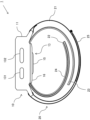
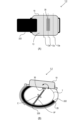
- FIG. 1 is a perspective view showing an outline of a biological information measuring device according to an embodiment of the present invention.
- FIG. 2 is a side view showing an outline of the biological information measuring device according to the embodiment.
- FIG. 3 is an explanatory diagram showing a positional relationship when the biological information measuring device according to the embodiment is worn on the wrist.
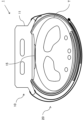
- FIG. 4 is an external view of the main body of the biological information measuring device according to the embodiment, as viewed from the bottom side.
- FIG. 5 is a block diagram illustrating a functional configuration of a biological information measuring device according to an embodiment.
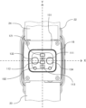
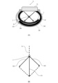
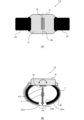
- 6A and 6B are diagrams illustrating the arrangement of the vital sensors according to the first embodiment.
- 7A and 7B are diagrams illustrating details of the arrangement of the vital sensors according to the first embodiment.
- 8A and 8B are diagrams illustrating the arrangement of vital sensors according to the second embodiment.
- 9A and 9B are diagrams illustrating the arrangement of vital sensors according to the third embodiment.
- 10A to 10C are diagrams illustrating the shape of the electrodes and the distance between the electrodes according to the fourth embodiment.
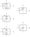
- 11A to 11E are diagrams for explaining the arrangement of electrodes according to the fifth embodiment.
- Example 1 An example of an embodiment of the present invention will be described below. However, unless otherwise specified, the dimensions, materials, shapes, relative positions, and the like of the components described in this example are not intended to limit the scope of the present invention to those alone.
- Fig. 1 is an external perspective view showing an outline of the configuration of a biological information measuring device 1 according to this embodiment.
- Fig. 2 is a side view showing an outline of the configuration of the biological information measuring device 1 according to this embodiment.
- the biological information measuring device 1 is generally a wristwatch-type wearable device having a main body 10 and a belt part 20, and can measure biological information such as a pulse wave (pulse), blood pressure value, and electrocardiogram waveform when worn on a wrist T of a human body.
- Fig. 3 shows the positional relationship between the wrist T and each component of the biological information measuring device 1 when the biological information measuring device 1 according to this embodiment is worn on the wrist T.
- the main body 10 includes a main body housing 11 and a cuff cover 16, which will be described later.
- the main body housing 11 is provided with a display 12 (e.g., an organic EL display), operation buttons 131 and 132, lugs 14, etc., as well as a sensor housing 15 that houses various sensors, which will be described later.
- the side on which the display 12 is formed is the surface of the main body housing 11, and the side on which the sensor housing 15 is formed is the bottom 13 of the main body housing 11.
- the operation buttons 131 and 132 are made of conductors, and also function as electrodes for measuring electrocardiogram waveforms.
- Figure 4 shows an external view of the main body 10 as viewed from the bottom 13 side.
- the bottom 13 of the main body housing 11 has a central area covered with a translucent resin cover and an area corresponding to the outer periphery, which is covered with a cuff cover 16.
- the sensor accommodating section 15 is located in the central area of the main body housing 11 in a plan view, is covered at the bottom 13 with a translucent resin cover, and is formed so as to protrude further towards the wrist T than the cuff cover 16 when worn, as shown in Figures 2 and 3.
- a first electrode 133 and a second electrode 134 are provided on the bottom 13 of the main body housing 11 so that their contact surfaces with the human body are exposed. Either the first electrode 133 or the second electrode 134 functions as a GND electrode when measuring the electrocardiogram waveform.
- the bioinformation measuring device 1 is worn, the contact surfaces of the first electrode 133 and the second electrode 134 are brought into contact with the skin surface of the wearing part, and the operation buttons 131, 132 are touched with the fingers of the hand on which the bioinformation measuring device 1 is not worn, thereby measuring the electrocardiogram waveform in I-lead.
- a charging terminal 192 is provided on the bottom 13 of the main body housing 11. By connecting the connection terminal of the power supply device to the charging terminal 192, the rechargeable battery (not shown in FIG. 4) can be charged.
- the belt section 20 includes a belt 21 and a hook-and-loop fastener 25 for fixing the biometric measuring device 1 to the wrist T, a first pressure cuff 22 and a second pressure cuff 23 for compressing an artery in the wrist T, and a sensing cuff 24 for detecting a pressure pulse wave.
- the connection parts of the cuffs 22, 23, and 24 and the main body housing 11 are covered with a cuff cover 16.
- the cuff cover 16 protects the connection parts of the cuffs 22, 23, and 24 and the main body housing 11, and also has the function of fixing the cuffs 22, 23, and 24 to the main body housing 11.
- the first pressure cuff 22 is provided on one side of the main body 10 in the circumferential direction
- the second pressure cuff 23 is provided on the other side of the main body 10 in the circumferential direction.
- the belt 21 corresponds to the belt section of the present invention
- the first pressure cuff 22 and the second pressure cuff 23 correspond to the multiple cuffs of the present invention.
- the wrist T corresponds to the arm of the present invention.
- the control board 17 also includes a processor such as a CPU (not shown), a memory such as a RAM, and other components, and controls the entire vital information measuring device 1.
- a processor such as a CPU (not shown)
- a memory such as a RAM
- other components and controls the entire vital information measuring device 1.
- the first LED 111 emits green light
- the second LED 113 emits red light and/or infrared light in addition to green light.
- a capacitor, an amplifier circuit, an A/D (Analog-to-Digital) conversion circuit, etc. are mounted on the first sensor board 101.
- Fig. 5 is a block diagram showing the functional configuration of the biological information measuring device 1.
- the biological information measuring device 1 has each of the functional units, namely, a pulse wave measuring unit 110, a blood oxygen saturation (SpO2) measuring unit 120, a blood pressure measuring unit 130, an electrocardiogram waveform measuring unit 140, a display unit 150, an operation unit 160, a communication unit 170, a storage unit 180, and a power supply unit 190.
- These functional units are realized by the processor of the control board 17 reading and executing a program from the memory, thereby controlling each of the components of the biological information measuring device 1.
- the pulse wave measuring unit 110 includes a first LED 111, a second LED 113, and a first PD 112, and measures the pulse wave and calculates the pulse rate by the so-called photoplethysmography method. Specifically, the first LED 111 and the second LED 113 emit green light, and the first PD 112 receives the light reflected inside the body, thereby detecting the blood flow rate (change in blood vessel volume) that changes with the heartbeat and measuring the pulse wave.
- the pulse wave corresponds to the biological information of the present invention, and the pulse wave measuring unit 110 corresponds to the biological information measuring means of the present invention.
- the first LED 111, the second LED 113, and the first PD 112 correspond to the sensor and sensor unit of the present invention.
- the SpO2 measuring unit 120 includes a second LED 113 and a second PD 121, and measures blood oxygen saturation from the intensity of the reflected light by receiving the reflected red light or infrared light emitted from the second LED 113 with the second PD 121.
- the blood oxygen saturation corresponds to the biological information of the present invention
- the SpO2 measuring unit 120 corresponds to the biological information measuring means of the present invention.
- the second LED 113 and the second PD 121 correspond to the sensor and sensor unit of the present invention.
- the blood pressure measurement unit 130 is composed of a piezoelectric pump, a valve, a pressure sensor, and a flow path plate (not shown), as well as a first pressure cuff 22, a second pressure cuff 23, and a sensing cuff 24, and measures blood pressure by the so-called oscillometric method. Blood pressure measurement by the oscillometric method is a well-known technique, so a detailed explanation will be omitted.
- the blood pressure measurement unit 130 corresponds to the blood pressure measurement means of the present invention.
- the electrocardiogram waveform measuring unit 140 is configured to include the operation buttons 131, 132, the first electrode 133 and the second electrode 134 provided on the bottom 13 of the main body housing 11, and an electrocardiogram waveform measuring circuit (not shown), and measures the electrocardiogram waveform using the so-called I-lead method. Specifically, the electrocardiogram waveform is measured based on the potential difference between the first electrode 133 and the second electrode 134 that contact the wrist T of one arm when worn, and the fingers of the other hand that touch the operation button 131 or 132 that functions as an electrode.
- the electrocardiogram waveform measuring unit 140 corresponds to the biological information measuring means of the present invention.
- the operation buttons 131, 132, the first electrode 133, and the second electrode 134 correspond to the sensor and sensor unit of the present invention.
- the display unit 150 includes a display 12 and displays various information such as biometric measurement results and menu screens.
- the operation unit 160 includes operation buttons 131 and 132 and accepts user input operations via these.
- the communication unit 170 includes an antenna (not shown) for wireless communication and communicates information with other electronic devices such as information processing terminals, for example, via BLE communication. It may also be provided with a terminal for wired communication.
- the storage unit 180 includes a main storage device (not shown) such as a RAM (Random Access Memory), and stores various information such as application programs and measured biometric information. In addition to the RAM, it may also include a long-term storage medium such as a flash memory.
- the power supply unit 190 includes a rechargeable battery and a charging terminal 192, and functions as a power supply source for each component of the biometric information measuring device 1.
- the vital sensor 30 refers to a sensor that contacts the wrist T of the human body when the vital information measuring device 1 is worn and measures the vital information.
- the first electrode 133 and the second electrode 134 for measuring the electrocardiogram waveform described in FIG. 4 correspond to the vital sensor 30, but are not limited thereto.
- FIG. 6 only one vital sensor 30 is shown, but this is a schematic representation of the vital sensor 30, and two vital sensors may be included, such as the first electrode 133 and the second electrode 134 described above, or when the vital sensor 30 is composed of a plurality of vital sensors, the number of the vital sensors is not limited.
- the vital sensor 30 corresponds to the sensor of the present invention.
- Fig. 6(A) is a schematic diagram showing the configuration of the vital information measuring device 1 as seen from the bottom 13 side.
- the vital information measuring device 1 has a rectangular vital sensor 30 disposed in approximately the center of the bottom 13 in the extension direction of the belt part 20 of the main body 10 (Y direction shown in Fig. 4, hereinafter also referred to as the longitudinal direction), and extending in a direction perpendicular to the extension direction of the belt part 20 (X direction shown in Fig. 4, hereinafter also referred to as the transverse direction).
- this position 13a position indicated by the dashed line in FIG. 6A
- the first pressure cuff 22 and the second pressure cuff 23 overlap on the inside of the wrist T, facing the main body 10 across the wrist T.
- the most inflatable portion 22e which is the portion where the first pressure cuff 22 expands most in the radial direction when pressurized
- the most inflatable portion 23e which is the portion where the second pressure cuff 23 expands most in the radial direction
- the force acting on the main body portion 10 through the belt portion 20 due to the expansion of the first pressure cuff 22 is shown as a vector V22 that passes through the center C of the wrist T and heads toward the most inflatable portion 22e
- the force acting on the main body portion 10 through the belt portion 20 due to the expansion of the second pressure cuff 23 is shown as a vector V23 that passes through the center C of the wrist T and heads toward the most inflatable portion 23e.
- the force acting on the main body portion 10 due to the expansion of the first pressure cuff 22 and the second pressure cuff 23 when pressurized can be represented as a resultant vector VT1 that is a combination of the vectors V22 and V23, as shown in FIG. 7(B).
- This resultant vector VT1 is also a vector that passes through the center C of the wrist T.
- the vital sensor 30 By providing the vital sensor 30 at the position where the extension line EL of the resultant vector VT1 representing the force acting on the main body 10 due to the expansion of the first and second pressure cuffs 22 and 23 intersects with the bottom 13 of the main body 10, the rotation moment around the axis in the X direction due to the force acting on the vital sensor 30 due to the expansion of the first and second pressure cuffs 22 and 23 during pressurization can be minimized. As a result, even if the first and second pressure cuffs 22 and 23 are expanded, the rotation of the vital sensor 30 around the axis in the X direction is suppressed.
- the center C of the wrist T is, for example, the center when the cross section of the wrist T taken in the arm direction is approximated by a circle or an ellipse, but is not limited thereto.
- the position where the extension line EL of the resultant vector VT intersects with the bottom 13 of the main body 10 corresponds to the change suppression position of the present invention.
- FIG. 6(A) and (B) show an example of the bioinformation measuring device 1 in which the circumferential length of the first pressure cuff 22 and the circumferential length of the second pressure cuff 23 are approximately equal.
- the above-mentioned vectors V22 and V23 are symmetrical with respect to a line connecting the center 200 of the overlapping portion of the first pressure cuff 22 and the second pressure cuff 23 and the center C of the wrist T, so that as shown in FIG. 6(B), the resultant vector VT1 overlaps with a line connecting the center 200 of the overlapping portion of the first pressure cuff 22 and the second pressure cuff 23 and the center C of the wrist T.
- the position where the extension line EL of the resultant vector VT1 shown in FIG. 7(B) intersects with the bottom 13 is position 13a shown in FIG. 6(A).
- the position 13a is on a straight line connecting the central portion 200 of the overlapping portion of the first pressure cuff 22 and the second pressure cuff 23 and the center C of the wrist T.
- the position 13a faces the central portion 200 of the overlapping portion of the first pressure cuff 22 and the second pressure cuff 23 on the outer circumference of the wrist T.
- the position 13a corresponds to the change suppression position of the present invention
- the central portion 200 corresponds to the central portion of the overlapping portion of the multiple cuffs of the present invention.
- circumferential length of the first pressure cuff 22 and the circumferential length of the second pressure cuff 23 are approximately equal, this does not necessarily mean that the circumferential lengths are completely equal, but also means that the circumferential lengths may differ slightly due to manufacturing errors, etc., and essentially means that the circumferential lengths are equal.
- Example 2 A biological information measuring device 1-2 according to Example 2 will be described below.
- the circumferential length of the first pressing cuff 22 and the circumferential length of the second pressing cuff 23 are substantially equal, but the biological information measuring device 1 according to Example 1 has a common configuration, except that the lengths are different as described below.
- the configuration common to Example 1 will be denoted by common reference numerals and detailed description will be omitted.
- the circumferential lengths being substantially equal does not necessarily mean that the circumferential lengths are completely equal, but also means that the circumferential lengths are slightly different due to manufacturing errors or the like, and means that the circumferential lengths are substantially equal.
- the biometric measuring device 1-2 includes a first pressure cuff 221 corresponding to the first pressure cuff 22 and a second pressure cuff 231 corresponding to the second pressure cuff 23.
- FIG. 8(B) when the biometric measuring device 1-2 is attached to the wrist T by the belt unit 20, the first pressure cuff 221 and the second pressure cuff 231 wrapped around the outer circumference of the wrist T do not overlap, and a gap 210 where no cuff is present on the outer circumference of the wrist T exists between the circumferential end 221a of the first pressure cuff 221 and the circumferential end 231a of the second pressure cuff 231.
- the position 13b where the vital sensor 30 is disposed on the bottom 13 is a position facing the center 210a of this gap 210 with the wrist T sandwiched therebetween.
- the gap 210 corresponds to the gap of the present invention.
- the position 13b corresponds to the change suppression position of the present invention.
- the resultant vector VT2 of a vector passing through the center C of the wrist T toward the most inflated part of the first pressure cuff 221 and a vector passing through the center C of the wrist T toward the most inflated part of the second pressure cuff 231 overlaps with a straight line connecting the center 210a of the gap 210 and the center C of the wrist T.
- the position where the extension of this resultant vector VT2 intersects with the bottom 13 is position 13b here.
- This position 13b is on the straight line connecting the center 210a of the gap 210 and the center C of the wrist T, that is, position 13b faces the center 210a of the gap 210 formed circumferentially between the circumferential end 221a of the first pressure cuff 221 and the circumferential end 231a of the second pressure cuff 231 on the outer periphery of the wrist T.
- Example 3 A biological information measuring device 1-3 according to Example 3 will be described below.
- the biological information measuring device 1-3 has a common configuration with the biological information measuring device 1 according to Example 1, except that the main body 10 is provided with only one pressure cuff 222, as described below.
- the common components with Example 1 are designated by common reference numerals and will not be described in detail.
- the biometric measuring device 1-3 has a pressure cuff 222 corresponding to the first pressure cuff 22, but does not have a pressure cuff corresponding to the second pressure cuff 23.
- FIG. 9(B) when the biometric measuring device 1-3 is fixed to the wrist T by the belt unit 20, the pressure cuff 222 wrapped around the circumference of the wrist T is inflated to press only a part of the circumference of the wrist T. At this time, the part where the pressure cuff 222 is most inflated in the outer diameter direction is the most inflatable part 220.
- the position 13c where the vital sensor 30 is arranged on the bottom part 13 is a position opposite the most inflatable part 220 with the wrist T sandwiched between them.
- the pressure cuff 222 When the pressure cuff 222 inflates during blood pressure measurement, the pressure cuff 222 inflates to the outermost side at the most inflatable part 220, so that a force indicated by a vector VF in the direction of the arrow passing through the center C of the wrist T acts on the main body unit 10 by the pressure cuff 222 and the belt unit 20.
- the position where the extension of this vector VF intersects with the bottom 13 of the main body 10 is position 13c.
- the vital sensor 30 is disposed at position 13c on the bottom 13, facing the most inflatable portion 220 across the wrist T, so that even if a rotation moment occurs around the axis in the X direction, it will be the smallest.
- position 13c corresponds to the change suppression position of the present invention.
- position 13d indicates the position facing the most inflatable portion 220 when it is assumed that the bioinformation measuring device 1-3 is worn by a person with the thinnest wrist T
- position 13e indicates the position facing the most inflatable portion 220 when it is worn by a person with the thickest wrist T.
- position 13d corresponds to the first change suppression position of the present invention
- position 13e corresponds to the second change suppression position of the present invention.
- Example 4 A biological information measuring device 1-4 according to Example 4 will be described below.
- the shape of the electrodes as an example of the vital sensor 30 is a specific shape.
- the entire configuration of the biological information measuring device 1-4, except for the shape of the electrodes, can be applied to any of the configurations of the biological information measuring devices 1, 1-2, and 1-3 according to Examples 1, 2, and 3. Therefore, for the configuration other than the electrodes, common reference numerals are used for the configuration common to these examples, and detailed description thereof will be omitted.
- Figure 10 (A) shows an example of the shape of electrodes as an example of vital sensor 30.
- the dotted line shown in Figure 10 (A) is the X-axis shown in Figure 4.
- Electrodes 301 to 303 are electrodes of preferred shapes. Electrode 301 is circular, and electrode 302 is square with four rounded corners, both of which are linearly symmetrical with respect to the X-axis direction. Electrodes 303 and 304 are both trapezoidal in shape, but while electrode 303 is linearly symmetrical with respect to the X-axis direction, electrode 304 is linearly symmetrical in the direction perpendicular to the X-axis (Y-axis direction).
- the electrodes 301-303 have a shape that is linearly symmetrical in the X-axis direction, the change in the contact area between the wrist T and the electrodes and the change in the pressure of the electrodes against the wrist when the main unit 10 is rotated can be further suppressed.
- the change in the position of the electrodes 301-303 relative to the wrist T is further suppressed, and changes in the contact area and pressure between the electrodes 301-303 and the wrist T are suppressed, enabling accurate measurement.
- one electrode is described, but the number of electrodes that make up the vital sensor 30 can be set as appropriate.
- FIG. 10B shows an example of the size of the electrodes.
- the roughly rectangular electrodes 311 and 312 shown in FIG. 10B are schematic representations of the size of the electrodes, and specifically, they have a shape similar to that of the electrodes 301 to 303.
- the size of the electrode 311 in the X-axis direction is larger than the size in the direction perpendicular to the X-axis.
- the change in the contact area between the wrist T and the electrode and the change in the pressure of the electrode against the wrist when the main body 10 is rotated can be suppressed, so that even if blood pressure measurement and measurement of an electrocardiogram waveform using the electrode 311 are performed simultaneously in parallel, the change in the posture of the electrode 311 with respect to the wrist T is suppressed, and the change in the contact area and pressure between the electrode 311 and the wrist T is further suppressed, enabling more accurate measurement.
- the electrode 311 can have a width of 12 to 13 mm in the direction perpendicular to the X-axis around the X-axis.
- FIG. 10C is a diagram explaining the spacing when multiple electrodes are provided.
- the roughly square electrodes 321 and 322 shown in FIG. 10C are an example for explaining the distance between the two electrodes, and the specific shape and size are as explained in FIG. 10A and FIG. 10B.
- the distance D in the X-axis direction between the electrodes 321 and 322 arranged side by side in the X-axis direction is preferably, for example, 40 mm or less. If the distance D between the electrodes 321 and 322 is about this distance, the contact state with the wrist T during blood pressure measurement becomes uniform, making it possible to measure the electrocardiogram waveform with higher accuracy at the same time as blood pressure measurement. On the other hand, if the distance D between the electrodes 321 and 322 is too wide, the contact state with the wrist T during blood pressure measurement becomes non-uniform, which may affect the accuracy of the measurement of the electrocardiogram waveform.
- Example 5 A biological information measuring device 1-5 according to Example 5 will be described below.
- the biological information measuring device 1-5 arranges electrodes at specific positions on the bottom 13. As described in Examples 1 to 3, there is a desirable position for the bottom 13, but since there is a degree of freedom in the position of the electrodes at that position, various configurations are possible for the number and arrangement of the electrodes.
- the entire configuration of the biological information measuring device 1-5, except for the arrangement of the electrodes, can be applied to any of the configurations of the biological information measuring devices 1, 1-2, and 1-3 according to Examples 1, 2, and 3, and therefore, for the configuration other than the electrodes, common reference numerals are used for the configuration common to these examples, and detailed description will be omitted.
- Figures 11(A) to (E) show examples of electrode placement on the bottom 13 of the biometric information measuring device 1-5.
- the X-axis direction is the elbow-wrist direction of the person wearing the biometric information measuring device 1-5
- the Y-axis direction is the longitudinal direction in which the belt part 20 extends.
- electrodes 331 and 332, which are symmetrical with respect to the X-axis are arranged along the X-axis direction so as to be symmetrical with respect to the Y-axis.
- electrodes 334 and 335 shown in FIG. 11(B) are arranged along the X-axis direction, with electrodes 331 and 332, which are symmetrical with respect to the X-axis, but electrodes 334 and 335 are arranged at positions offset in the X-axis direction with respect to the bottom 13.
- electrodes 331 and 332 are arranged evenly in the X-axis direction as with electrodes 334 and 335, and electrodes are arranged offset in the X-axis direction with respect to the bottom 13 as with electrodes 334 and 335, it is possible to suppress changes in the contact area between the wrist T and the electrodes due to rotation of the main body 10 around the X-axis and changes in the pressure of the electrodes against the wrist, and it is possible to measure blood pressure and electrocardiogram waveforms with high accuracy at the same time.
- the electrodes 356 and 357 shown in FIG. 11(C) are evenly spaced in the X direction on the bottom 13, but are arranged asymmetrically with respect to the X axis. However, when viewed in the X direction, the electrodes 356 and 357 are arranged so that they overlap in the center in the Y direction. Even with this arrangement, it is possible to suppress changes in the contact area between the wrist T and the electrodes caused by rotation of the main body 10 about the X axis, and changes in the pressure of the electrodes against the wrist, making it possible to measure blood pressure and electrocardiogram waveforms with high accuracy at the same time.
- electrode 338 is positioned at the center of bottom 13 in the X and Y directions.
- electrode 339 shown in Fig. 11(E) is positioned at the center of bottom 13 in the Y direction, but offset from the center of bottom 13 in the X direction. Even with this positioning, it is possible to suppress changes in the contact area between wrist T and electrode and changes in pressure of electrode against wrist caused by rotation of main body 10 about the X axis, making it possible to measure blood pressure and electrocardiogram waveforms with high accuracy at the same time.
- Reference Signs List 1 Biological information measuring device 10: Main body 13a, 13b, 13c, 13d, 13e: Position 20: Belt 22: First pressure cuff 22e: Maximum expansion part 23: Second pressure cuff 23e: Maximum expansion part 30: Vital sensor 110: Pulse wave measuring part 120: SpO2 measuring part 130: Blood pressure measuring part 140: Electrocardiogram waveform measuring part 133: First electrode 134: Second electrode T: Wrist
Landscapes
- Health & Medical Sciences (AREA)
- Life Sciences & Earth Sciences (AREA)
- Cardiology (AREA)
- Physics & Mathematics (AREA)
- Engineering & Computer Science (AREA)
- Surgery (AREA)
- Veterinary Medicine (AREA)
- Biophysics (AREA)
- Biomedical Technology (AREA)
- Heart & Thoracic Surgery (AREA)
- Medical Informatics (AREA)
- Molecular Biology (AREA)
- Pathology (AREA)
- Animal Behavior & Ethology (AREA)
- General Health & Medical Sciences (AREA)
- Public Health (AREA)
- Physiology (AREA)
- Vascular Medicine (AREA)
- Ophthalmology & Optometry (AREA)
- Optics & Photonics (AREA)
- Spectroscopy & Molecular Physics (AREA)
- Signal Processing (AREA)
- Pulmonology (AREA)
- Dentistry (AREA)
- Measuring Pulse, Heart Rate, Blood Pressure Or Blood Flow (AREA)
- Measurement And Recording Of Electrical Phenomena And Electrical Characteristics Of The Living Body (AREA)
Abstract
Description
人体の血圧を測定するためのカフを含む血圧測定手段と、
前記血圧とは異なる生体情報を測定する生体情報測定手段と、
前記人体の腕部の外周に巻かれて固定され、内周側に設けられた前記カフを前記腕部の前記外周に配置するベルト部と、
装着状態において前記腕部に接触する側に位置する底部を含む本体部と、
前記底部に設けられ、前記腕部に接触して前記生体情報を測定するためのセンサと、
を備え、
前記本体部に対して前記ベルト部の延長方向の両側に複数の前記カフが設けられ、
前記センサは、
それぞれの前記カフが膨張したときに、径方向に最も膨張する部位である、それぞれの前記カフの最膨張部に向け、前記腕部の中心部を通って作用する力のベクトルを合成した合成ベクトルの延長線上の前記底部の位置であって、前記カフの膨張による前記センサの前記腕部に対する接触状態の変化を抑制し得る、前記底部の変化抑制位置に配置されたことを特徴とする生体情報測定装置である。
ここで、接触状態は、センサの、腕部に対する角度及び位置の少なくともいずれかを含む。
前記センサは、2以上のセンサ部を含み、該センサ部は、前記ベルト部の延長方向に直交する方向に並んで配置されていてもよい。
複数の前記カフの周方向の長さが略等しく、前記変化抑制位置が、複数の前記カフの膨張時に前記腕部の前記外周において、複数の前記カフが重なる部位の中央部に対向するようにしてもよい。
ここで、腕部の外周において「対向」するとは、腕部の中心部を挟んで、変化抑制位置と、複数のカフが重なる部位の中央部とが、腕部の中心部を通る同一直線上に位置することである。また、複数のカフの周方向の長さが略等しい場合とは、複数のカフの周方向の長さが完全に等しい場合に限らず、複数のカフの周方向の長さが製造誤差等により若干異なる場合も含み、実質的な意味において、複数のカフの周方向の長さが等しい場合という趣旨である。
複数の前記カフの長さが略等しく、前記装着状態において、複数の前記カフの周方向端部の間に周方向に間隙が形成され、
前記変化抑制位置は、複数の前記カフの膨張時に前記腕部の前記外周において、前記間隙の中央部に対向するようにしてもよい。
ここで、腕部の外周において「対向」するとは、腕部の中心部を挟んで、変化抑制位置と、周方向の端部間の間隙の中央部とが、腕部の中心部を通る同一直線上に位置することである。また、複数のカフの周方向の長さが略等しい場合とは、複数のカフの周方向の長さが完全に等しい場合に限らず、複数のカフの周方向の長さが製造誤差等により若干異なる場合も含み、実質的な意味において、複数のカフの周方向の長さが等しい場合という趣旨である。
人体の血圧を測定するためのカフを含む血圧測定手段と、
前記血圧とは異なる生体情報を測定する生体情報測定手段と、
前記人体の腕部の外周に巻かれて固定され、内周側に設けられた前記カフを前記腕部の前記外周に配置するベルト部と、
装着状態において前記腕部に接触する側に位置する底部を含む本体部と、
前記底部に設けられ、前記腕部に接触して前記生体情報を測定するためのセンサと、
を備え、
前記カフは、前記本体部に対して、前記ベルト部の延長方向に一つ設けられ、
前記センサが配置される、前記カフの膨張による前記センサの前記腕部に対する接触状態の変化を抑制し得る、前記底部の変化抑制位置は、前記カフの膨張時に前記腕部の前記外周において、前記カフが径方向に最も膨張する部位である最膨張部に対向することを特徴とする生体情報測定装置である。
ここで、腕部の外周において「対向」するとは、腕部の中心部を挟んで、変化抑制位置とカフの最膨張部とが、腕部の中心部を通る同一直線上に位置することである。
前記センサは、2以上のセンサ部を含み、該センサ部は、前記ベルト部の延長方向に直交する方向に並んで配置されていてもよい。
人体の血圧を測定するためのカフを含む血圧測定手段と、
前記血圧とは異なる生体情報を測定する生体情報測定手段と、
前記人体の腕部の外周に巻かれて固定され、内周側に設けられた前記カフを前記腕部の前記外周に配置するベルト部と、
装着状態において前記腕部に接触する側に位置する底部を含む本体部と、
前記底部に設けられ、前記腕部に接触して前記生体情報を測定するためのセンサと、
を備え、
前記カフは、前記本体部に対して、前記ベルト部の延長方向に一つ設けられ、
前記センサは、
前記底部の位置であって、前記カフが膨張したときに、該位置から該カフが径方向に最も膨張する部位である最膨張部に向けて作用する力のベクトルが、想定される最も細い前記腕部の中心部を通ることとなる、前記カフの膨張による前記センサの前記腕部に対する接触状態の変化を抑制し得る、前記底部の第1変化抑制位置と、
前記底部の他の位置であって、前記カフが膨張したときに、前記最膨張部に向けて作用する力のベクトルが、想定される最も太い前記腕部の中心部を通ることとなる、前記カフの膨張による前記センサの前記腕部に対する接触状態の変化を抑制し得る、前記底部の第2変化抑制位置と、
の間に配置されたことを特徴とする生体情報測定装置である。
前記血圧とは異なる生体情報を測定する生体情報測定手段と、
前記人体の腕部の外周に巻かれて固定され、内周側に設けられた前記カフを前記腕部の前記外周に配置するベルト部と、
装着状態において前記腕部に接触する側に位置する底部を含む本体部と、
前記底部に設けられ、前記腕部に接触して前記生体情報を測定するためのセンサと、
を備え、
前記センサは、2以上のセンサ部を含み、該センサ部は、前記ベルト部の延長方向に直交する方向に並んで配置されていることを特徴とする生体情報測定装置。
前記センサ部は、前記ベルト部の延長方向に直交する方向から見て、少なくとも一部が重なっているようにしてもよい。
人体の血圧を測定するためのカフを含む血圧測定手段と、
前記血圧とは異なる生体情報を測定する生体情報測定手段と、
前記人体の腕部の外周に巻かれて固定され、内周側に設けられた前記カフを前記腕部の前記外周に配置するベルト部と、
装着状態において前記腕部に接触する側に位置する底部を含む本体部と、
前記底部に設けられ、前記腕部に接触して前記生体情報を測定するためのセンサと、
を備え、
前記本体部に対して、前記ベルト部の延長方向の両側に、周方向の長さが略等しい複数の前記カフが設けられ、
前記センサは、前記腕部の前記外周において、複数の前記カフが重なる部位の中央部に対向することを特徴とする生体情報測定装置である。
ここで、腕部の外周において「対向」するとは、腕部の中心部を挟んで、センサと、複数のカフが重なる部位の中央部とが、腕部の中心部を通る同一直線上に位置することである。また、周方向の長さが略等しいとは、複数のカフの周方向の長さが完全に等しい場合に限らず、複数のカフの周方向の長さが製造誤差等により若干異なる場合も含み、実質的な意味において、複数のカフの周方向の長さが等しいという趣旨である。
人体の血圧を測定するためのカフを含む血圧測定手段と、
前記血圧とは異なる生体情報を測定する生体情報測定手段と、
前記人体の腕部の外周に巻かれて固定され、内周側に設けられた前記カフを前記腕部の前記外周に配置するベルト部と、
装着状態において前記腕部に接触する側に位置する底部を含む本体部と、
前記底部に設けられ、前記腕部に接触して前記生体情報を測定するためのセンサと、
を備え、
前記本体部に対して、前記ベルト部の延長方向の両側に、周方向の長さが略等しい複数の前記カフが設けられ、
前記装着状態において、複数の前記カフの周方向端部の間に周方向に間隙が形成され、
前記センサは、前記腕部の前記外周において、前記間隙の中央部に対向することを特徴とする生体情報測定装置である。
ここで、腕部の外周において「対向」するとは、腕部の中心部を挟んで、センサと、周方向の端部間の間隙の中央部とが、腕部の中心部を通る同一直線上に位置することである。また、周方向の長さが略等しいとは、複数のカフの周方向の長さが完全に等しい場合に限らず、複数のカフの周方向の長さが製造誤差等により若干異なる場合も含み、実質的な意味において、複数のカフの周方向の長さが等しいという趣旨である。
人体の血圧を測定するためのカフを含む血圧測定手段と、
前記血圧とは異なる生体情報を測定する生体情報測定手段と、
前記人体の腕部の外周に巻かれて固定され、内周側に設けられた前記カフを前記腕部の前記外周に配置するベルト部と、
装着状態において前記腕部に接触する側に位置する底部を含む本体部と、
前記底部に設けられ、前記腕部に接触して前記生体情報を測定するためのセンサと、
を備え、
前記カフは、前記本体部に対して、前記ベルト部の延長方向に一つ設けられ、
前記センサは、前記カフの膨張時に前記腕部の前記外周において、前記カフが径方向に最も大きく膨張する最膨張部に対向することを特徴とする生体情報測定装置である。
ここで、腕部の外周において「対向」するとは、腕部の中心部を挟んで、センサとカフの最膨張部とが、腕部の中心部を通る同一直線上に位置することである。
前記生体情報測定手段は、前記人体の心電波形を測定し、
前記センサは、前記心電波形を検出する電極であるようにしてもよい。
前記電極は、前記ベルト部の延長方向に直交する方向に対して線対称となる形状を有するようにしてもよい。
以下に、本発明の実施形態の一例について説明する。但し、この実施例に記載されている構成部品の寸法、材質、形状、その相対配置などは、特に記載がない限りは、この発明の範囲をそれらのみに限定する趣旨のものではない。
図1は、本実施例に係る生体情報測定装置1の構成の概略を示す外観斜視図である。また、図2は、本実施例に係る生体情報測定装置1の構成の概略を示す側面図である。図1、図2に示すように、生体情報測定装置1は概略、本体部10と、ベルト部20を有する腕時計型のウェアラブル装置であり、人体の手首Tに装着した状態で脈波(脈拍)、血圧値、心電波形などの生体情報を測定することができる。図3に、本実施例に係る生体情報測定装置1を手首Tに装着した際の手首Tと生体情報測定装置1の各構成との配置関係を示す。
次に、生体情報測定装置1の機能構成について説明する。図5は、生体情報測定装置1の機能構成を示すブロック図である。図5に示すように、本実施例に係る生体情報測定装置1は、脈波測定部110、血中酸素飽和度(SpO2)測定部120、血圧測定部130、心電波形測定部140、表示部150、操作部160、通信部170、記憶部180、電源部190、の各機能部を有している。これらの機能部は、制御基板17のプロセッサがメモリからプログラムを読み出して実行することによって、生体情報測定装置1の各構成を制御することによって実現される。
以下に、本実施例に係る生体情報測定装置1の本体部10の底部13におけるバイタルセンサ30の配置について説明する。
バイタルセンサ30は、生体情報測定装置1の装着時に、人体の手首Tに接触し、生体情報を測定するためのセンサを示す。例えば、図4で説明した、心電波形を測定するための第1電極133及び第2電極134が該当するが、これに限られない。図6では、バイタルセンサ30として1つのみ表示しているが、これはバイタルセンサ30を模式的に示すものであり、上述の第1電極133及び第2電極134ように2つのバイタルセンサを含んでもよいし、バイタルセンサ30が複数のバイタルセンサから構成される場合に、その数は限定されない。ここでは、バイタルセンサ30が、本発明のセンサに相当する。
以下に、実施例2に係る生体情報測定装置1-2について説明する。生体情報測定装置1-2は、第1押圧カフ22の周方向の長さと第2押圧カフ23の周方向の長さは略等しいが、以下に説明するようにそれらの長さが、実施例1に係る生体情報測定装置1と異なる点を除いて、共通の構成を有する。実施例1と共通の構成については、共通の符号を用いて詳細な説明は省略する。なお、ここでも、周方向の長さが略等しいとは、周方向の長さが完全に等しい場合に限らず、周方向の長さが製造誤差等により若干異なる場合も含み、実質的な意味において、周方向の長さが等しい場合という趣旨である。
以下に、実施例3に係る生体情報測定装置1-3について説明する。生体情報測定装置1-3は、以下に説明するように本体部10に対して一つの押圧カフ222のみを備える点を除き実施例1に係る生体情報測定装置1と共通の構成を有する。実施例1と共通の構成については、共通の符号を用いて詳細な説明は省略する。
以下に実施例4に係る生体情報測定装置1-4について説明する。生体情報測定装置1-4は、バイタルセンサ30の例としての電極の形状を特定の形状としたものである。生体情報測定装置1-4は、電極の形状を除く全体構成は、実施例1、2及び3に係る生体情報測定装置1、1-2、1-3のいずれの構成も適用することができるので、電極以外の構成については、これらの実施例と共通する構成については共通する符号を用いて詳細な説明は省略する。
これに対して、電極312のように、X軸方向の大きさに比べ、X軸に直交する方向の大きさを大きくすることも考えられる。ただし、本体部10のX軸回りの回転による手首Tと電極との接触面積の変化や、手首対する電極の押圧の変化を抑制するためには、電極311のような大きさが望ましい。
以下に実施例5に係る生体情報測定装置1-5について説明する。生体情報測定装置1-5は、底部13において電極を特定の位置に配置するものである。実施例1~3において説明したように底部13に対して望ましい位置が存在するが、その位置での電極の位置の自由度はあるので、電極の数や配置に対して種々の構成が可能である。生体情報測定装置1-5は、電極の配置を除く全体構成は、実施例1、2及び3に係る生体情報測定装置1、1-2、1-3のいずれの構成も適用することができるので、電極以外の構成については、これらの実施例と共通する構成については共通する符号を用いて詳細な説明は省略する。
10・・・本体部
13a,13b,13c,13d,13e・・・位置
20・・・ベルト部
22・・・第1押圧カフ
22e・・最膨張部
23・・・第2押圧カフ
23e・・最膨張部
30・・・バイタルセンサ
110・・・脈波測定部
120・・・SpO2測定部
130・・・血圧測定部
140・・・心電波形測定部
133・・・第1電極
134・・・第2電極
T・・・手首
Claims (14)
- 人体の血圧を測定するためのカフを含む血圧測定手段と、
前記血圧とは異なる生体情報を測定する生体情報測定手段と、
前記人体の腕部の外周に巻かれて固定され、内周側に設けられた前記カフを前記腕部の前記外周に配置するベルト部と、
装着状態において前記腕部に接触する側に位置する底部を含む本体部と、
前記底部に設けられ、前記腕部に接触して前記生体情報を測定するためのセンサと、
を備え、
前記本体部に対して、前記ベルト部の延長方向の両側に複数の前記カフが設けられ、
前記センサは、
それぞれの前記カフが膨張したときに、径方向に最も膨張する部位である、それぞれの前記カフの最膨張部に向け、前記腕部の中心部を通って作用する力のベクトルを合成した合成ベクトルの延長線上の前記底部の位置であって、前記カフの膨張による前記センサの前記腕部に対する接触状態の変化を抑制し得る、前記底部の変化抑制位置に配置されたことを特徴とする生体情報測定装置。 - 前記センサは、2以上のセンサ部を含み、該センサ部は、前記ベルト部の延長方向に直交する方向に並んで配置されていることを特徴とする請求項1に記載の生体情報測定装置。
- 複数の前記カフの周方向の長さが略等しく、前記変化抑制位置が、複数の前記カフの膨張時に前記腕部の前記外周において、複数の前記カフが重なる部位の中央部に対向することを特徴とする請求項1に記載の生体情報測定装置。
- 複数の前記カフの長さが略等しく、前記装着状態において、複数の前記カフの周方向端部の間に周方向に間隙が形成され、
前記変化抑制位置は、複数の前記カフの膨張時に前記腕部の前記外周において、前記間隙の中央部に対向することを特徴とする請求項1に記載の生体情報測定装置。 - 人体の血圧を測定するためのカフを含む血圧測定手段と、
前記血圧とは異なる生体情報を測定する生体情報測定手段と、
前記人体の腕部の外周に巻かれて固定され、内周側に設けられた前記カフを前記腕部の前記外周に配置するベルト部と、
装着状態において前記腕部に接触する側に位置する底部を含む本体部と、
前記底部に設けられ、前記腕部に接触して前記生体情報を測定するためのセンサと、
を備え、
前記カフは、前記本体部に対して、前記ベルト部の延長方向に一つ設けられ、
前記センサが配置される、前記カフの膨張による前記センサの前記腕部に対する接触状態の変化を抑制し得る、前記底部の変化抑制位置は、前記カフの膨張時に前記腕部の前記外周において、前記カフが径方向に最も膨張する部位である最膨張部に対向することを特徴とする生体情報測定装置。 - 前記センサは、2以上のセンサ部を含み、該センサ部は、前記ベルト部の延長方向に直交する方向に並んで配置されていることを特徴とする請求項5に記載の生体情報測定装置。
- 人体の血圧を測定するためのカフを含む血圧測定手段と、
前記血圧とは異なる生体情報を測定する生体情報測定手段と、
前記人体の腕部の外周に巻かれて固定され、内周側に設けられた前記カフを前記腕部の前記外周に配置するベルト部と、
装着状態において前記腕部に接触する側に位置する底部を含む本体部と、
前記底部に設けられ、前記腕部に接触して前記生体情報を測定するためのセンサと、
を備え、
前記カフは、前記本体部に対して、前記ベルト部の延長方向に一つ設けられ、
前記センサは、
前記底部の位置であって、前記カフが膨張したときに、該位置から該カフが径方向に最も膨張する部位である最膨張部に向けて作用する力のベクトルが、想定される最も細い前記腕部の中心部を通ることとなる、前記カフの膨張による前記センサの前記腕部に対する接触状態の変化を抑制し得る、前記底部の第1変化抑制位置と、
前記底部の他の位置であって、前記カフが膨張したときに、前記最膨張部に向けて作用する力のベクトルが、想定される最も太い前記腕部の中心部を通ることとなる、前記カフの膨張による前記センサの前記腕部に対する接触状態の変化を抑制し得る、前記底部の第2変化抑制位置と、
の間に配置されたことを特徴とする生体情報測定装置。 - 人体の血圧を測定するためのカフを含む血圧測定手段と、
前記血圧とは異なる生体情報を測定する生体情報測定手段と、
前記人体の腕部の外周に巻かれて固定され、内周側に設けられた前記カフを前記腕部の前記外周に配置するベルト部と、
装着状態において前記腕部に接触する側に位置する底部を含む本体部と、
前記底部に設けられ、前記腕部に接触して前記生体情報を測定するためのセンサと、
を備え、
前記センサは、2以上のセンサ部を含み、該センサ部は、前記ベルト部の延長方向に直交する方向に並んで配置されていることを特徴とする生体情報測定装置。 - 前記センサ部は、前記ベルト部の延長方向に直交する方向から見て、少なくとも一部が重なっていることを特徴とする請求項8に記載の生体情報測定装置。
- 人体の血圧を測定するためのカフを含む血圧測定手段と、
前記血圧とは異なる生体情報を測定する生体情報測定手段と、
前記人体の腕部の外周に巻かれて固定され、内周側に設けられた前記カフを前記腕部の前記外周に配置するベルト部と、
装着状態において前記腕部に接触する側に位置する底部を含む本体部と、
前記底部に設けられ、前記腕部に接触して前記生体情報を測定するためのセンサと、
を備え、
前記本体部に対して、前記ベルト部の延長方向の両側に、周方向の長さが略等しい複数の前記カフが設けられ、
前記センサは、前記腕部の前記外周において、複数の前記カフが重なる部位の中央部に対向することを特徴とする生体情報測定装置。 - 人体の血圧を測定するためのカフを含む血圧測定手段と、
前記血圧とは異なる生体情報を測定する生体情報測定手段と、
前記人体の腕部の外周に巻かれて固定され、内周側に設けられた前記カフを前記腕部の前記外周に配置するベルト部と、
装着状態において前記腕部に接触する側に位置する底部を含む本体部と、
前記底部に設けられ、前記腕部に接触して前記生体情報を測定するためのセンサと、
を備え、
前記本体部に対して、前記ベルト部の延長方向の両側に周方向の長さが略等しい複数の前記カフが設けられ、
前記装着状態において、複数の前記カフの周方向端部の間に周方向に間隙が形成され、
前記センサは、前記腕部の前記外周において、前記間隙の中央部に対向することを特徴とする生体情報測定装置。 - 人体の血圧を測定するためのカフを含む血圧測定手段と、
前記血圧とは異なる生体情報を測定する生体情報測定手段と、
前記人体の腕部の外周に巻かれて固定され、内周側に設けられた前記カフを前記腕部の前記外周に配置するベルト部と、
装着状態において前記腕部に接触する側に位置する底部を含む本体部と、
前記底部に設けられ、前記腕部に接触して前記生体情報を測定するためのセンサと、
を備え、
前記カフは、前記本体部に対して、前記ベルト部の延長方向に一つ設けられ、
前記センサは、前記カフの膨張時に前記腕部の前記外周において、前記カフが径方向に最も大きく膨張する最膨張部に対向することを特徴とする生体情報測定装置。 - 前記生体情報測定手段は、前記人体の心電波形を測定し、
前記センサは、前記心電波形を検出する電極であることを特徴とする請求項1乃至12のいずれか1項に記載の生体情報測定装置。 - 前記電極は、前記ベルト部の延長方向に直交する方向に対して線対称となる形状を有することを特徴とする請求項13に記載の生体情報測定装置。
Priority Applications (3)
| Application Number | Priority Date | Filing Date | Title |
|---|---|---|---|
| CN202480025338.4A CN120957655A (zh) | 2023-06-06 | 2024-01-30 | 生物体信息测定装置 |
| DE112024000871.2T DE112024000871T5 (de) | 2023-06-06 | 2024-01-30 | Messvorrichtung für biologische informationen |
| US19/363,124 US20260041327A1 (en) | 2023-06-06 | 2025-10-20 | Biological information measurement device |
Applications Claiming Priority (2)
| Application Number | Priority Date | Filing Date | Title |
|---|---|---|---|
| JP2023-093422 | 2023-06-06 | ||
| JP2023093422A JP2024175553A (ja) | 2023-06-06 | 2023-06-06 | 生体情報測定装置 |
Related Child Applications (1)
| Application Number | Title | Priority Date | Filing Date |
|---|---|---|---|
| US19/363,124 Continuation US20260041327A1 (en) | 2023-06-06 | 2025-10-20 | Biological information measurement device |
Publications (1)
| Publication Number | Publication Date |
|---|---|
| WO2024252721A1 true WO2024252721A1 (ja) | 2024-12-12 |
Family
ID=93795193
Family Applications (1)
| Application Number | Title | Priority Date | Filing Date |
|---|---|---|---|
| PCT/JP2024/002938 Ceased WO2024252721A1 (ja) | 2023-06-06 | 2024-01-30 | 生体情報測定装置 |
Country Status (5)
| Country | Link |
|---|---|
| US (1) | US20260041327A1 (ja) |
| JP (1) | JP2024175553A (ja) |
| CN (1) | CN120957655A (ja) |
| DE (1) | DE112024000871T5 (ja) |
| WO (1) | WO2024252721A1 (ja) |
Citations (5)
| Publication number | Priority date | Publication date | Assignee | Title |
|---|---|---|---|---|
| JP2009240511A (ja) * | 2008-03-31 | 2009-10-22 | Citizen Holdings Co Ltd | 生体測定装置 |
| JP2016000153A (ja) * | 2014-06-12 | 2016-01-07 | オムロンヘルスケア株式会社 | 脈拍測定装置、脈拍測定方法、および、脈拍測定プログラム |
| JP2019048009A (ja) * | 2017-09-12 | 2019-03-28 | オムロンヘルスケア株式会社 | 血圧推定装置 |
| JP2020028421A (ja) * | 2018-08-22 | 2020-02-27 | オムロンヘルスケア株式会社 | 測定装置、測定方法及び測定プログラム |
| WO2022249459A1 (ja) * | 2021-05-28 | 2022-12-01 | オムロンヘルスケア株式会社 | 生体情報測定装置 |
-
2023
- 2023-06-06 JP JP2023093422A patent/JP2024175553A/ja active Pending
-
2024
- 2024-01-30 WO PCT/JP2024/002938 patent/WO2024252721A1/ja not_active Ceased
- 2024-01-30 DE DE112024000871.2T patent/DE112024000871T5/de active Pending
- 2024-01-30 CN CN202480025338.4A patent/CN120957655A/zh active Pending
-
2025
- 2025-10-20 US US19/363,124 patent/US20260041327A1/en active Pending
Patent Citations (5)
| Publication number | Priority date | Publication date | Assignee | Title |
|---|---|---|---|---|
| JP2009240511A (ja) * | 2008-03-31 | 2009-10-22 | Citizen Holdings Co Ltd | 生体測定装置 |
| JP2016000153A (ja) * | 2014-06-12 | 2016-01-07 | オムロンヘルスケア株式会社 | 脈拍測定装置、脈拍測定方法、および、脈拍測定プログラム |
| JP2019048009A (ja) * | 2017-09-12 | 2019-03-28 | オムロンヘルスケア株式会社 | 血圧推定装置 |
| JP2020028421A (ja) * | 2018-08-22 | 2020-02-27 | オムロンヘルスケア株式会社 | 測定装置、測定方法及び測定プログラム |
| WO2022249459A1 (ja) * | 2021-05-28 | 2022-12-01 | オムロンヘルスケア株式会社 | 生体情報測定装置 |
Also Published As
| Publication number | Publication date |
|---|---|
| US20260041327A1 (en) | 2026-02-12 |
| DE112024000871T5 (de) | 2025-12-11 |
| CN120957655A (zh) | 2025-11-14 |
| JP2024175553A (ja) | 2024-12-18 |
Similar Documents
| Publication | Publication Date | Title |
|---|---|---|
| JP7338830B2 (ja) | 圧力センサアレイを用いた血圧信号測定システム | |
| TWM553986U (zh) | 腕式血壓計 | |
| JP2017209434A (ja) | センサアセンブリ | |
| JP7404975B2 (ja) | ベルト、及び、心電測定装置 | |
| CN119818036A (zh) | 一种检测装置、电子设备及其控制方法 | |
| JP2024175553A (ja) | 生体情報測定装置 | |
| US20240197189A1 (en) | Biological information measurement device | |
| TWI617288B (zh) | 壓力感測器及血壓量測裝置 | |
| US20250120593A1 (en) | Biometric information measurement device | |
| JP2019130092A (ja) | 生体情報測定装置 | |
| US20240057875A1 (en) | Biological information measurement device | |
| WO2024161714A1 (ja) | 生体情報測定装置 | |
| WO2025164035A1 (ja) | 生体情報測定装置 | |
| US20240197252A1 (en) | Biological information measurement device | |
| CN116157066B (zh) | 血压计 | |
| JP6837881B2 (ja) | 生体情報測定装置、方法及びプログラム | |
| WO2025124339A1 (zh) | 气囊、腕带及可穿戴式电子设备 | |
| TW202547417A (zh) | 血壓量測裝置 | |
| WO2025192008A1 (ja) | 生体情報測定装置 | |
| TW202245682A (zh) | 脈診裝置 | |
| CN119654102A (zh) | 生物体信息测定装置 | |
| JP2021159150A (ja) | 補助部材及び検出装置 |
Legal Events
| Date | Code | Title | Description |
|---|---|---|---|
| 121 | Ep: the epo has been informed by wipo that ep was designated in this application |
Ref document number: 24818960 Country of ref document: EP Kind code of ref document: A1 |
|
| WWE | Wipo information: entry into national phase |
Ref document number: 202517092489 Country of ref document: IN |
|
| WWE | Wipo information: entry into national phase |
Ref document number: 112024000871 Country of ref document: DE |
|
| WWP | Wipo information: published in national office |
Ref document number: 202517092489 Country of ref document: IN |
|
| WWE | Wipo information: entry into national phase |
Ref document number: CN2024800253384 Country of ref document: CN |
|
| WWP | Wipo information: published in national office |
Ref document number: 112024000871 Country of ref document: DE |
|
| 122 | Ep: pct application non-entry in european phase |
Ref document number: 24818960 Country of ref document: EP Kind code of ref document: A1 |