WO2024252699A1 - 通信用アンテナを備えたドローンおよびこのドローンを用いた監視システム並びに監視方法 - Google Patents
通信用アンテナを備えたドローンおよびこのドローンを用いた監視システム並びに監視方法 Download PDFInfo
- Publication number
- WO2024252699A1 WO2024252699A1 PCT/JP2023/046168 JP2023046168W WO2024252699A1 WO 2024252699 A1 WO2024252699 A1 WO 2024252699A1 JP 2023046168 W JP2023046168 W JP 2023046168W WO 2024252699 A1 WO2024252699 A1 WO 2024252699A1
- Authority
- WO
- WIPO (PCT)
- Prior art keywords
- drone
- tag
- reflector
- antenna
- camera
- Prior art date
- Legal status (The legal status is an assumption and is not a legal conclusion. Google has not performed a legal analysis and makes no representation as to the accuracy of the status listed.)
- Ceased
Links
Images






Classifications
-
- B—PERFORMING OPERATIONS; TRANSPORTING
- B64—AIRCRAFT; AVIATION; COSMONAUTICS
- B64D—EQUIPMENT FOR FITTING IN OR TO AIRCRAFT; FLIGHT SUITS; PARACHUTES; ARRANGEMENT OR MOUNTING OF POWER PLANTS OR PROPULSION TRANSMISSIONS IN AIRCRAFT
- B64D1/00—Dropping, ejecting, releasing or receiving articles, liquids, or the like, in flight
- B64D1/22—Taking-up articles from earth's surface
-
- B—PERFORMING OPERATIONS; TRANSPORTING
- B64—AIRCRAFT; AVIATION; COSMONAUTICS
- B64C—AEROPLANES; HELICOPTERS
- B64C1/00—Fuselages; Constructional features common to fuselages, wings, stabilising surfaces or the like
- B64C1/36—Fuselages; Constructional features common to fuselages, wings, stabilising surfaces or the like adapted to receive antennas or radomes
-
- B—PERFORMING OPERATIONS; TRANSPORTING
- B64—AIRCRAFT; AVIATION; COSMONAUTICS
- B64D—EQUIPMENT FOR FITTING IN OR TO AIRCRAFT; FLIGHT SUITS; PARACHUTES; ARRANGEMENT OR MOUNTING OF POWER PLANTS OR PROPULSION TRANSMISSIONS IN AIRCRAFT
- B64D45/00—Aircraft indicators or protectors not otherwise provided for
-
- B—PERFORMING OPERATIONS; TRANSPORTING
- B64—AIRCRAFT; AVIATION; COSMONAUTICS
- B64U—UNMANNED AERIAL VEHICLES [UAV]; EQUIPMENT THEREFOR
- B64U10/00—Type of UAV
- B64U10/10—Rotorcrafts
- B64U10/13—Flying platforms
-
- B—PERFORMING OPERATIONS; TRANSPORTING
- B64—AIRCRAFT; AVIATION; COSMONAUTICS
- B64U—UNMANNED AERIAL VEHICLES [UAV]; EQUIPMENT THEREFOR
- B64U10/00—Type of UAV
- B64U10/10—Rotorcrafts
- B64U10/13—Flying platforms
- B64U10/14—Flying platforms with four distinct rotor axes, e.g. quadcopters
-
- B—PERFORMING OPERATIONS; TRANSPORTING
- B64—AIRCRAFT; AVIATION; COSMONAUTICS
- B64U—UNMANNED AERIAL VEHICLES [UAV]; EQUIPMENT THEREFOR
- B64U20/00—Constructional aspects of UAVs
- B64U20/80—Arrangement of on-board electronics, e.g. avionics systems or wiring
- B64U20/87—Mounting of imaging devices, e.g. mounting of gimbals
-
- B—PERFORMING OPERATIONS; TRANSPORTING
- B64—AIRCRAFT; AVIATION; COSMONAUTICS
- B64U—UNMANNED AERIAL VEHICLES [UAV]; EQUIPMENT THEREFOR
- B64U30/00—Means for producing lift; Empennages; Arrangements thereof
- B64U30/20—Rotors; Rotor supports
-
- B—PERFORMING OPERATIONS; TRANSPORTING
- B64—AIRCRAFT; AVIATION; COSMONAUTICS
- B64U—UNMANNED AERIAL VEHICLES [UAV]; EQUIPMENT THEREFOR
- B64U50/00—Propulsion; Power supply
- B64U50/10—Propulsion
- B64U50/19—Propulsion using electrically powered motors
-
- B—PERFORMING OPERATIONS; TRANSPORTING
- B64—AIRCRAFT; AVIATION; COSMONAUTICS
- B64U—UNMANNED AERIAL VEHICLES [UAV]; EQUIPMENT THEREFOR
- B64U50/00—Propulsion; Power supply
- B64U50/30—Supply or distribution of electrical power
-
- F—MECHANICAL ENGINEERING; LIGHTING; HEATING; WEAPONS; BLASTING
- F16—ENGINEERING ELEMENTS AND UNITS; GENERAL MEASURES FOR PRODUCING AND MAINTAINING EFFECTIVE FUNCTIONING OF MACHINES OR INSTALLATIONS; THERMAL INSULATION IN GENERAL
- F16L—PIPES; JOINTS OR FITTINGS FOR PIPES; SUPPORTS FOR PIPES, CABLES OR PROTECTIVE TUBING; MEANS FOR THERMAL INSULATION IN GENERAL
- F16L11/00—Hoses, i.e. flexible pipes
- F16L11/04—Hoses, i.e. flexible pipes made of rubber or flexible plastics
- F16L11/12—Hoses, i.e. flexible pipes made of rubber or flexible plastics with arrangements for particular purposes, e.g. specially profiled, with protecting layer, heated, electrically conducting
- F16L11/133—Hoses, i.e. flexible pipes made of rubber or flexible plastics with arrangements for particular purposes, e.g. specially profiled, with protecting layer, heated, electrically conducting buoyant
-
- G—PHYSICS
- G06—COMPUTING OR CALCULATING; COUNTING
- G06K—GRAPHICAL DATA READING; PRESENTATION OF DATA; RECORD CARRIERS; HANDLING RECORD CARRIERS
- G06K7/00—Methods or arrangements for sensing record carriers, e.g. for reading patterns
- G06K7/10—Methods or arrangements for sensing record carriers, e.g. for reading patterns by electromagnetic radiation, e.g. optical sensing; by corpuscular radiation
-
- H—ELECTRICITY
- H01—ELECTRIC ELEMENTS
- H01Q—ANTENNAS, i.e. RADIO AERIALS
- H01Q1/00—Details of, or arrangements associated with, antennas
- H01Q1/27—Adaptation for use in or on movable bodies
-
- H—ELECTRICITY
- H01—ELECTRIC ELEMENTS
- H01Q—ANTENNAS, i.e. RADIO AERIALS
- H01Q1/00—Details of, or arrangements associated with, antennas
- H01Q1/27—Adaptation for use in or on movable bodies
- H01Q1/28—Adaptation for use in or on aircraft, missiles, satellites, or balloons
-
- H—ELECTRICITY
- H01—ELECTRIC ELEMENTS
- H01Q—ANTENNAS, i.e. RADIO AERIALS
- H01Q13/00—Waveguide horns or mouths; Slot antennas; Leaky-waveguide antennas; Equivalent structures causing radiation along the transmission path of a guided wave
- H01Q13/08—Radiating ends of two-conductor microwave transmission lines, e.g. of coaxial lines, of microstrip lines
-
- H—ELECTRICITY
- H01—ELECTRIC ELEMENTS
- H01Q—ANTENNAS, i.e. RADIO AERIALS
- H01Q19/00—Combinations of primary active antenna elements and units with secondary devices, e.g. with quasi-optical devices, for giving the antenna a desired directional characteristic
- H01Q19/10—Combinations of primary active antenna elements and units with secondary devices, e.g. with quasi-optical devices, for giving the antenna a desired directional characteristic using reflecting surfaces
-
- H—ELECTRICITY
- H01—ELECTRIC ELEMENTS
- H01Q—ANTENNAS, i.e. RADIO AERIALS
- H01Q21/00—Antenna arrays or systems
- H01Q21/06—Arrays of individually energised antenna units similarly polarised and spaced apart
-
- H—ELECTRICITY
- H01—ELECTRIC ELEMENTS
- H01Q—ANTENNAS, i.e. RADIO AERIALS
- H01Q21/00—Antenna arrays or systems
- H01Q21/06—Arrays of individually energised antenna units similarly polarised and spaced apart
- H01Q21/061—Two dimensional planar arrays
- H01Q21/065—Patch antenna array
-
- B—PERFORMING OPERATIONS; TRANSPORTING
- B64—AIRCRAFT; AVIATION; COSMONAUTICS
- B64U—UNMANNED AERIAL VEHICLES [UAV]; EQUIPMENT THEREFOR
- B64U2101/00—UAVs specially adapted for particular uses or applications
- B64U2101/20—UAVs specially adapted for particular uses or applications for use as communications relays, e.g. high-altitude platforms
-
- B—PERFORMING OPERATIONS; TRANSPORTING
- B64—AIRCRAFT; AVIATION; COSMONAUTICS
- B64U—UNMANNED AERIAL VEHICLES [UAV]; EQUIPMENT THEREFOR
- B64U2101/00—UAVs specially adapted for particular uses or applications
- B64U2101/25—UAVs specially adapted for particular uses or applications for manufacturing or servicing
- B64U2101/26—UAVs specially adapted for particular uses or applications for manufacturing or servicing for manufacturing, inspections or repairs
-
- B—PERFORMING OPERATIONS; TRANSPORTING
- B64—AIRCRAFT; AVIATION; COSMONAUTICS
- B64U—UNMANNED AERIAL VEHICLES [UAV]; EQUIPMENT THEREFOR
- B64U2101/00—UAVs specially adapted for particular uses or applications
- B64U2101/30—UAVs specially adapted for particular uses or applications for imaging, photography or videography
Definitions
- the present invention relates to a drone equipped with an antenna for communicating with a passive IC tag installed on an object to be monitored, and a monitoring system and monitoring method using this drone.
- a monitoring system has been proposed that uses a communication device mounted on a drone to obtain pressure data in a marine hose from a passive IC tag attached to the marine hose, and determines the presence or absence of a fluid leak based on this pressure data (see, for example, Patent Document 1).
- the wireless communication distance between the passive IC tag and the communication device is generally 2 m or less. Therefore, when performing this wireless communication, it is necessary to position the drone in an upper position close to the IC tag and hover it so that the antenna of the communication device is within, for example, 2 m of the IC tag. Therefore, it is desirable to install the antenna as low as possible relative to the drone, and it is also desirable to have antenna specifications that can increase the wireless communication distance with the IC tag.
- the drone operator positions the drone in an upper position close to the IC tag by referring to image data captured by the camera device mounted on the drone. Therefore, it is necessary that the antenna mounted on the drone is not in a position that gets in the way when the camera device acquires image data. It is also necessary to ensure that the presence of the camera device does not adversely affect the wireless communication between the antenna and the IC tag. Furthermore, even with an antenna specification that can increase the wireless communication distance with the IC tag, the load on the drone increases as the weight of the antenna increases, shortening the flight time. Therefore, there is room for improvement in reducing the weight of the antenna mounted on the drone while maintaining good wireless communication between this antenna and the IC tag, and more reliably acquiring monitoring data from the IC tag. Note that monitoring based on data acquired from passive IC tags using a communication device mounted on a drone in this way can be applied not only to marine hoses but also to other monitored objects.
- the object of the present invention is to provide a drone equipped with a lightweight antenna that can maintain better wireless communication with a passive IC tag installed on a monitored object, as well as a monitoring system and monitoring method using this drone.
- the drone of the present invention is a drone equipped with a communication device and a camera device equipped with an antenna used for wireless communication with a passive IC tag installed on a monitored object, the antenna being a two-element patch antenna having a reflector and two plate-shaped antenna elements arranged side by side at a distance on the underside of the reflector, the reflector and each of the antenna elements being formed from an aluminum alloy plate having a thickness of 3 mm or less, a camera through hole being formed in a position corresponding to the space between each of the antenna elements in the center of the reflector, the reflector being installed on the drone so that the camera through hole is located in the center of the drone in a plan view, the reflector and each of the antenna elements appear in a field of view looking up from directly below the drone, the camera device being positioned above the reflector, and image data below the drone being acquired by the camera device through the camera through hole.
- the antenna being a two-element patch antenna having a reflector and two plate-shaped antenna elements arranged side by side at
- the monitoring system of the present invention is a monitoring system for an object to be monitored that includes the above-mentioned drone, the IC tag installed on the object to be monitored, and a computing device to which monitoring data acquired by the communication device from the IC tag via wireless communication is input, and is characterized in that the IC tag stores detection data from a sensor unit that detects the state of the object to be monitored, the detection data acquired by the communication device from the IC tag via wireless communication is used as the monitoring data, and the computing device determines the state of the object to be monitored based on the monitoring data.
- the monitoring method of the present invention is a method for monitoring an object to be monitored using the above-mentioned drone, the IC tag installed on the object to be monitored, and a computing device to which monitoring data acquired from the IC tag by the communication device via wireless communication is input, and is characterized in that the state of the object to be monitored is detected by a sensor unit installed on the object to be monitored, the detection data by the sensor unit is stored in the IC tag, the detection data is acquired from the IC tag by the communication device via wireless communication, this detection data is used as the monitoring data, and the state of the object to be monitored is judged by the computing device based on the monitoring data.
- a two-element patch antenna is used as the antenna constituting the communication device mounted on the drone, and the reflector and each of the antenna elements are formed from an aluminum alloy plate having a thickness of 3 mm or less, making it easier to increase the wireless communication distance with the IC tag while reducing the weight of the antenna. Furthermore, since the reflector and each of the antenna elements are visible when looking up from directly below the drone, the antenna can wirelessly communicate with the IC tag without being obstructed by the camera device or other parts of the communication device.
- the camera through-hole which is formed at a position corresponding to between each of the antenna elements in the center of the reflector, is located in the center of the drone in a plan view.
- the camera device arranged above the reflector acquires image data below the drone through the camera through-hole, so that the drone operator can refer to this image data to the advantage of accurately positioning the drone in an upper position close to the IC tag and hovering it.
- it becomes possible to maintain better wireless communication between the IC tag and the antenna which is advantageous for more reliably acquiring data indicating the status of the monitored object from the IC tag.
- the monitoring system and monitoring method of the present invention can maintain better wireless communication between the IC tag and the antenna, so the monitoring data stored in the IC tag can be acquired more reliably. This is advantageous for accurately grasping the state of the monitored object. Furthermore, because a lightweight drone is used, the drone's flight time per flight is increased, which is advantageous for performing monitoring work quickly.
- FIG. 1 is an explanatory diagram illustrating an embodiment of a drone from a front view.
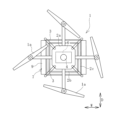
- FIG. 2 is an explanatory diagram illustrating the drone of FIG. 1 in a plan view.
- FIG. 3 is an explanatory diagram illustrating a camera device and an antenna in a cross-sectional view taken along line AA in FIG.
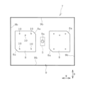
- FIG. 4 is an explanatory diagram illustrating the antenna of FIG. 3 as viewed from below.
- FIG. 5 is a cross-sectional view taken along line BB of FIG.
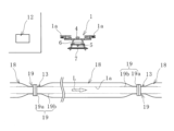
- FIG. 6 is a diagram illustrating an embodiment of a surveillance system.
- FIG. 7 is an explanatory diagram illustrating an example of a part of the marine hose of FIG. 6 in an enlarged vertical cross-sectional view.
- FIG. 7 is an explanatory diagram illustrating an example of a part of the marine hose of FIG. 6 in an enlarged vertical cross-sectional view.
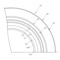
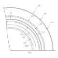
- FIG. 8 is an explanatory diagram illustrating a part of the marine hose in a cross-sectional view taken along the line CC in FIG.
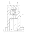
- FIG. 9 is an explanatory diagram illustrating an enlarged vertical cross-sectional view of the IC tag and its periphery in FIG.
- FIG. 10 is an explanatory diagram illustrating a schematic configuration of a monitoring system in which a computing device and terminal devices are connected via a communication network.
- FIG. 11 is an explanatory diagram illustrating another embodiment of a monitoring system in an enlarged vertical cross-sectional view of a part of a marine hose.
- FIG. 12 is an explanatory diagram illustrating a part of the marine hose in a cross-sectional view taken along the line DD in FIG.
- the embodiment of the drone 1 illustrated in Figures 1 and 2 is used to grasp the status of various monitored objects.
- the arrows W, D, and H in the figures indicate the width, depth, and height directions of the drone 1, respectively.
- the monitored object is, for example, a floating marine hose 18 used while floating on the water surface, as shown in Figure 6.
- the communication device 6 mounted on the drone 1 wirelessly communicates with a passive type 3 installed on the marine hose 18.
- the radio waves (R1, R2) used for this wireless communication are right-handed circularly polarized waves.
- the frequency of these radio waves (R1, R2) is mainly in the UHF band (range 860MHz to 930MHz, which varies by country; in Japan, 915MHz to 930MHz), although the HF band (13.56MHz) is sometimes used.
- the drone 1 has multiple propellers 1a, supports 2a, 2b, and 2c spaced apart vertically, and four legs 3.
- a frame structure is constructed by the supports 2a, 2b, and 2c and the legs 3, and one propeller 1a is installed on each arm extending from the topmost support 2a.
- the drone 1 is not limited to the structure illustrated in this embodiment, and various known structures can be adopted.
- This drone 1 is equipped with a GNSS receiver 4, a camera device 5, and a communication device 6.
- the GNSS receiver 4 can be of various known specifications.
- the camera device 5 can be of various known digital cameras capable of acquiring still or video image data. Currently, very small and lightweight camera devices 5 are commercially available, so such a camera device 5 can be used.
- the communication device 6 can be of various known specifications capable of wireless communication with a passive RFID tag.
- the drone 1 is also equipped with an altimeter, a battery to operate the on-board equipment, and the like.
- the GNSS receiver 4 is mounted on the top support 2a and is located in the center of the drone 1 in a plan view.
- the camera device 5 and the main body of the communication device 6 are mounted on the middle support 2b.
- the camera device 5 is located in the center of the drone 1 in a plan view.
- the photographing lens of the camera device 5 faces downward.
- the antenna 7 that constitutes the communication device 6 is mounted on the bottom support 2c.
- the antenna 7 and the main body of the communication device 6 are connected by a cable.
- the antenna 7 is fixed to the drone 1 via an insulator.
- the antenna 7 is a two-element patch antenna having a reflector 9 and two plate-shaped antenna elements 8 arranged side by side with a gap between them on the underside of the reflector 9.
- the reflector 9 and each antenna element 8 are made of the same material, and are formed from an aluminum alloy plate having a thickness of 3 mm or less.
- Various known aluminum alloys can be used, such as Al-Mg and Al-Mg-Si aluminum alloy plates.
- the size is, for example, a width of 400 mm to 500 mm, a depth of 300 mm to 480 mm, and a height (thickness) of 0.5 mm to 3 mm.
- the reflector 9 is not limited to a rectangle, and can be other shapes such as a square, a circle, or an ellipse.
- a camera through hole 9a is formed at a position corresponding to between each of the antenna elements 8 in the center of the reflector 9 in a plan view, penetrating the reflector 9 from top to bottom.
- the diameter of the camera through hole 9a is 50 mm or less, and preferably, for example, 10 mm or more and 40 mm or less.
- the diameter of the photographing lens of the camera device 5 is 10 mm or less.
- the photographing lens of the camera device 5 and the camera through hole 9a are arranged coaxially above and below. Therefore, the camera device 5 arranged above the reflector 9 can acquire image data below the drone 1 through the camera through hole 9a.
- Each antenna element 8 has the same shape, a roughly rectangular shape, with notches 8a formed at two opposing corners of the rectangle.
- the size of each roughly rectangular antenna element 8 is, for example, a width dimension that is about 30% of the width dimension of the reflector 9, a depth dimension that is about 50% of the width dimension of the reflector 9, and a height dimension (thickness) that is 0.5 mm or more and 3 mm or less.
- each antenna element 8 has a notch 8a at the upper right and lower left corners, but instead, it can be designed to have notches 8a at the upper left and lower right corners.
- Each antenna element 8 is disposed at a distance in the width direction W.
- the distance between the antenna elements 8 in the width direction W (the distance between the opposing sides) is, for example, 80 mm or more and 120 mm or less.
- the distance between the centers of each antenna element 8 is, for example, 240 mm or more and 260 mm or less.
- Each antenna element 8 is fixed to the reflector 9 by an insulating fixing part 10. More specifically, as shown in FIG. 5, each antenna element 8 and the reflector 9 are arranged with a gap between them using the insulating fixing part 10 so that no current flows between them.
- the insulating fixing part 10 has an insulating spacer interposed between the antenna element 8 and the reflector 9.
- the gap in the height direction H between each antenna element 8 and the reflector 9 is, for example, about 10 mm.
- Each antenna element 8 is connected to a distributor 11 fixed to the upper surface of the reflector 9 through a conductive wire (communication cable) that passes through the inside of one insulating fixing part 10.
- a communication cable that is connected to the main body of the communication device 6 is connected to this distributor 11. Therefore, each antenna element 8 is electrically connected to the main body of the communication device 6 via the distributor 11.
- the reflector 9 is installed on the drone 1 so that the through hole 9a for the camera is located in the center of the drone 1 in a plan view. Furthermore, in the field of view looking up at the drone 1 from directly below, substantially the entire range of the reflector 9 and each of the antenna elements 8 is visible, as illustrated in Figure 4. In other words, with this drone 1, there is substantially nothing located directly below the reflector 9 and each of the antenna elements 8.
- the total mass of the reflector 9 and each antenna element 8 is preferably 1.2 kg or less, more preferably 1.0 kg or less, and even more preferably 0.8 kg or less.
- the reflector 9 and each antenna element 8 are more preferably 2 mm or less in thickness, and even more preferably 1.5 mm or less in thickness.
- the thickness of the reflector 9 and each antenna element 8 is 0.5 mm or more, and more preferably 1 mm or more.
- the reflector 9 has a shape in which the peripheral portion 9b is bent downward.
- the peripheral portion 9b bent downward it is possible to compensate for the lack of bending rigidity that occurs when the reflector 9 is made thinner.
- the thickness of the reflector 9 is 1 mm or less, it is preferable to make the peripheral portion 9b bent downward.
- the entire area (whole circumference) of the peripheral portion 9b is bent downward, but it is also possible to bend only a part of the peripheral portion 9b of the reflector 9, such as only the peripheral portions 9b of two opposing sides, downward.
- the bend dimension (height dimension H) of the peripheral portion 9b bent downward is, for example, 10 mm or more and 20 mm or less.
- the specifications of the antenna 7 are set to the appropriate range described above, taking into consideration the improvement of the gain of the antenna 7 when wireless communication between the antenna 7 and the IC tag 13 and the weight reduction of the antenna 7.
- the antenna 7 is a one-element patch antenna having one antenna element 8
- the antenna element 8 is basically placed in the center of the reflector 9. Therefore, even if a camera through hole 9a is formed in the center of the reflector 9, it is blocked by the antenna element 8, so it is necessary to form the camera through hole 9a in another position.
- the frequency characteristics of the antenna 7 when wireless communication with the IC tag 13 changes depending on the position of the camera through hole 9a.
- the antenna 7 is made a two-element patch antenna and the camera through hole 9a is formed in a position corresponding to between the respective antenna elements 8 in the center of the reflector 9, it has been found that the frequency characteristics of the antenna 7 when wireless communication with the IC tag 13 hardly changes depending on the presence or absence of the camera through hole 9a. Therefore, in this embodiment, the antenna 7 has these specifications.
- an embodiment of the monitoring system of the present invention includes the drone 1 described above, an IC tag 13 attached to a marine hose 18 that is the object to be monitored, and a computing device 12 to which monitoring data acquired by a communication device 6 from the IC tag 13 via wireless communication is input.
- the computing device 12 is located remotely from the location where the marine hose 18 is used, and the communication device 6 and the computing device 12 are configured to be separate and independent, but the communication device 6 and the computing device 12 can also be integrated and mounted on the drone 1.
- a known computer is used as the arithmetic unit 12, which performs various arithmetic processes using input data.
- the arithmetic unit 12 receives as input the monitoring data acquired from the IC tag 13 by the communication device 6 and the image data acquired by the camera device 5.
- a marine hose 18 is composed of a cylindrical hose body and connecting fittings 19 connected to both ends of the hose body in the longitudinal direction.
- Each connecting fitting 19 has a nipple 19b extending in the longitudinal direction of the hose body and a flange 19a joined to the nipple 19b.
- Marine hoses 18 are connected to each other via the connecting fittings 19, and generally about 10 marine hoses 18 are connected together for use.
- the hose body of the marine hose 18 is laminated in the following order from the inner circumference to the outer circumference: inner surface layer 20, first reinforcing layer 21, main body wire layer 22, fluid retention layer 24, second reinforcing layer 23, buoyancy layer 25, and outer surface layer 26.
- This marine hose 18 is a double carcass type having the first reinforcing layer 21 and the second reinforcing layer 23 laminated at intervals in the radial direction of the hose body with the fluid retention layer 24 interposed therebetween.
- the main body wire layer 22 can be provided as desired.
- the inner circumference region of the inner surface layer 20 becomes the flow path 18a for the fluid L.
- the fluid L include crude oil, heavy oil, gasoline, LPG, water, seawater, and chemicals (alcohols refined from gasoline).
- the first reinforcing layer 21, main body wire layer 22, and second reinforcing layer 23 are fixed to the nipples 19b using nipple wires 21w, 22w, and 23w at both ends of each layer, and fixing rings 19c protruding from the outer circumferential surfaces of the nipples 19b at both ends of the hose main body.
- the fluid retention layer 24 formed between the first reinforcing layer 21 and the second reinforcing layer 23 serves as a space for storing the fluid L leaking from the flow path 18a.
- the IC tag 13 is housed in a casing 27 that is erected on the surface of the marine hose 18 (the outer surface of the nipple 19b) and is located above the water.
- the IC tag 13 has an IC chip 13a that is installed on a substrate 15 and an antenna section 14 that is connected to the IC chip 13a.
- the IC chip 13a stores tag-specific information such as the identification number of the IC tag 13, as well as any other necessary information.
- a commonly available specification is adopted for the IC tag 13, and an RFID tag, for example, can be used.
- a sensor unit 16 that detects the state of the marine hose 18 is connected to the IC tag 13 (IC chip 13a). In this embodiment, a pressure sensor is used as the sensor unit 16. Note that in FIG. 9, the IC chip 13a and sensor unit 16 are in a suspended state, but they can also be laid flat like the antenna unit 14.
- the IC tag 13 and the sensor unit 16 are arranged in the upper space of the casing 27.
- a check valve 28 is installed at the bottom of this upper space.
- a communication pipe 29 that communicates with the fluid retention layer 24 is connected to the lower space of the casing 27. Therefore, the check valve 28 is interposed between the upper space and the lower space of the casing 27.
- the check valve 28 only allows the flow of fluid L and gas into the upper space, and regulates the flow from the upper space to the lower space. Therefore, when the pressure value in the upper space rises, that pressure state is maintained.
- a publicly known check valve 28 may be used.
- the sensor unit 16 detects the pressure value in the upper space, and the detection data is stored in the IC tag 13 (IC chip 13a).
- drone 1 is flown from a measurement base, such as on land or on a ship, and moved into the air above marine hose 18.
- the position coordinates of drone 1 are grasped in real time by GNSS receiver 4.
- Drone 1 can be flown to a desired location by a drone operator wirelessly controlling it using a controller communicatively connected to computing device 12.
- drone 1 can also be flown from the measurement base to the desired location by automatic control operation.
- the drone 1 After the drone 1 has been moved into the air above the marine hose 18, the drone 1 is moved downward to bring the communication device 6 close to the IC tag 13 in order to perform wireless communication between the IC tag 13 and the communication device 6.
- the drone operator refers to the image data (image data of the top view of the marine hose 18) acquired in real time by the camera device 5, and positions and hovers the drone 1 so that the antenna 7 is close to the IC tag 13 (antenna unit 14) (for example, within 1 to 2 m of the IC tag 13), as shown in the example of FIG. 7.
- the camera through-hole 9a which is formed at a position corresponding to between each of the antenna elements 8 in the center of the reflector 9, is located in the center of the drone 1 in a plan view.
- the camera device 5 arranged above the reflector 9 acquires image data below the drone 1 through the camera through-hole 9a, and by referring to this image data, the drone operator can advantageously position the drone 1 accurately at an upper position close to the IC tag 13 (for example, within 1 to 2 m of the IC tag 13) and hover it. In other words, the drone 1 can be positioned so that the IC tag 13 is located in the center of the acquired image data.
- the antenna 7 transmits outgoing radio waves R1 to the IC tag 13.
- the outgoing radio waves R1 received by the antenna section 14 constituting the IC tag 13 generate power in the IC tag 13, activating the IC tag 13.
- the activated IC tag 13 uses this power to transmit a reply radio wave R2 through the antenna section 14.
- This reply radio wave R2 is received by the antenna 7.
- wireless communication is performed between the IC tag 13 and the communication device 6 by transmitting the reply radio wave R2 in response to the outgoing radio wave R1.
- the detection data (pressure data) from the sensor unit 16 stored in the IC tag 13 is acquired by the communication device 6.
- the calculation device 12 uses the detection data acquired by the communication device 6 as monitoring data and judges the state of the marine hose 18 based on this monitoring data.
- the pressure value in the fluid retention layer 24 in a healthy state where fluid L is not leaking from the flow path 18a is determined in advance by performing a preliminary test or the like, and set as a reference value.
- the calculation device 12 compares the magnitude of the acquired monitoring data with the preset reference value. If the monitoring data is equal to or less than the reference value, the calculation device 12 determines that fluid L is not leaking, and if the monitoring data is greater than the reference value, the calculation device 12 determines that fluid L is leaking.
- a temperature sensor can be used as the sensor unit 16. By using a temperature sensor, it is possible to determine whether or not there is abnormal heating inside the marine hose 18.
- the antenna 7 constituting the communication device 6 by adopting a two-element patch antenna with the above-mentioned specifications as the antenna 7 constituting the communication device 6, it becomes easier to increase the wireless communication distance between the antenna 7 and the IC tag 13. In other words, the frequency characteristics of the antenna 7 when wirelessly communicating with the IC tag 13 hardly change depending on whether or not there is a through hole 9a for the camera, and the antenna gain can be improved compared to a one-element patch antenna.
- the antenna 7 can communicate wirelessly with the IC tag 13 more stably without being blocked by the camera device 5 or other parts of the communication device 6. As a result, it becomes possible to maintain wireless communication between the IC tag 13 and the antenna 7 in better condition, which is advantageous for more reliably obtaining monitoring data indicating the status of the marine hose 18 from the IC tag 13. This is therefore advantageous for accurately grasping the status of the marine hose 18.
- the reflector 9 and each antenna element 8 are made of an aluminum alloy plate with a thickness of 3 mm or less. Therefore, the weight of the antenna 7 is reduced, which reduces the load on the drone 1 and increases the flight time of the drone 1 per flight, which is advantageous for performing surveillance work quickly.
- the arithmetic device 12 is connected to desired terminal devices 17 via a communication network such as the Internet.
- various information (data) can be transmitted from the arithmetic device 12 to terminal devices 17 of related parties such as the management office of the operating company (user) of the marine hose 18, which is located remotely from the place where the marine hose 18 is used, the sales company of the marine hose 18, and the manufacturing company.
- the arithmetic device 12 can sequentially transmit monitoring data acquired by the communication device 6 and the results of judgments made by the arithmetic device 12 to each terminal device 17.
- the IC tag 13 can be installed in the fluid retention layer 24 at a predetermined position in the longitudinal direction of the marine hose 18.
- This IC tag 13 is placed in the fluid retention layer 24 during the process (molding process) of manufacturing the marine hose 18, and is fixed in the fluid retention layer 24 by vulcanization adhesion or the like.
- This IC tag 13 is designed so that the wireless communication state (communication strength) changes when it comes into contact with the fluid L.
- a target mark indicating the buried position of the IC tag 13 is attached to the surface of the outer layer 26 corresponding to the buried position of the IC tag 13.
- the strength of the reply radio wave R2 when wireless communication is performed between the communication device 6 and the IC tag 13 is ascertained in advance by performing a pre-test or the like and set as a reference value.
- the drone operator refers to the image data (image data of the top view of the marine hose 18) acquired in real time by the camera device 5, positions the drone 1 at the target mark described above so that the antenna 7 is in a position close to the IC tag 13 (antenna section 14) as shown in FIG. 11, and hovers the drone 1.
- the strength of the reply radio wave R2 when wireless communication is performed between the communication device 6 and the IC tag 13 during hovering is used as monitoring data.
- the calculation device 12 compares the acquired monitoring data with the magnitude of a preset reference value and determines whether or not there is leakage of the fluid L based on the comparison result.
- the reflector 9 can also be designed to have many ventilation holes that penetrate vertically in addition to the camera through-hole 9a. It is advisable to scatter many ventilation holes on the reflector 9 within a range that ensures the minimum required rigidity of the reflector 9.
- By designing the reflector 9 to have many ventilation holes it is possible to reduce the air resistance that the reflector 9 experiences while the drone 1 is flying or hovering. This is advantageous for moving the drone 1 to a desired position with high precision and hovering it.
- the power consumption by the drone 1 is reduced, which is also advantageous for increasing the flight time of the drone 1 per flight.
- the monitored object is not limited to the marine hose 18, but other examples include conveyor belts, pneumatic fenders, and extra-large tires for construction vehicles.
- the communication device 6 mounted on the drone 1 is used to grasp the state of the monitored object based on monitoring data acquired from a passive IC tag 13 attached to the monitored object.
- the present invention can also be used to grasp the state of monitored objects stored in warehouses, factories, etc.
- the present invention can be applied for the purpose of inventory management of monitored objects, and the temperature and internal pressure state of monitored objects stored can be grasped.
Landscapes
- Engineering & Computer Science (AREA)
- Aviation & Aerospace Engineering (AREA)
- Mechanical Engineering (AREA)
- Physics & Mathematics (AREA)
- Remote Sensing (AREA)
- General Physics & Mathematics (AREA)
- Combustion & Propulsion (AREA)
- Chemical & Material Sciences (AREA)
- General Engineering & Computer Science (AREA)
- Artificial Intelligence (AREA)
- Microelectronics & Electronic Packaging (AREA)
- Theoretical Computer Science (AREA)
- Computer Vision & Pattern Recognition (AREA)
- Toxicology (AREA)
- General Health & Medical Sciences (AREA)
- Electromagnetism (AREA)
- Astronomy & Astrophysics (AREA)
- Health & Medical Sciences (AREA)
- Arrangements For Transmission Of Measured Signals (AREA)
- Rigid Pipes And Flexible Pipes (AREA)
- Aerials With Secondary Devices (AREA)
- Variable-Direction Aerials And Aerial Arrays (AREA)
- Waveguide Aerials (AREA)
- Details Of Aerials (AREA)
Abstract
Description
1a プロペラ
2a、2b、2c 支持体
3 脚部
4 GNSS受信機
5 カメラ装置
6 通信機
7 アンテナ
8 アンテナ素子(パッチ)
8a 切欠き
9 反射板
9a カメラ用貫通穴
9b 周縁部
10 絶縁固定部
11 分配器
12 演算装置
13 ICタグ
13a ICチップ
14 アンテナ部
15 基板
16 センサ部
17 端末機器
18 マリンホース(監視対象物)
18a 流路
19 連結金具
19a フランジ
19b ニップル
19c 固定リング
20 内面層
21 第一補強層
21w ニップルワイヤ
22 本体ワイヤ層
22w ニップルワイヤ
23 第二補強層
23w ニップルワイヤ
24 流体滞留層
25 浮力層
26 外面層
27 ケーシング
28 逆止弁
29 連通管
Claims (7)
- 監視対象物に設置されているパッシブ型のICタグとの無線通信に使用されるアンテナを備えた通信機およびカメラ装置が搭載されたドローンにおいて、
前記アンテナが、反射板とこの反射板の下面に間隔をあけて並置されている2枚の板状のアンテナ素子とを有する2素子型パッチアンテナであり、
前記反射板およびそれぞれの前記アンテナ素子は厚さ3mm以下のアルミニウム合金板で形成されていて、
前記反射板の中央部のそれぞれの前記アンテナ素子の間に相当する位置にカメラ用貫通穴が形成されていて、
前記反射板は前記カメラ用貫通穴が平面視で前記ドローンの中央部に位置するように前記ドローンに設置されていて、前記ドローンを真下から見上げた視野では前記反射板およびそれぞれの前記アンテナ素子が現れていて、
前記カメラ装置は前記反射板の上方に配置されていて、前記カメラ用貫通穴を通じて前記ドローンの下方の画像データが前記カメラ装置により取得される構成にしたドローン。 - 前記反射板およびそれぞれの前記アンテナ素子の合計質量が1.2kg以下である請求項1に記載のドローン。
- 前記反射板は、その周縁部が下方に折り曲げられた形状である請求項1または2に記載のドローン。
- 前記反射板に、前記カメラ用貫通穴とは別に上下に貫通する通気孔が多数形成されている請求項1~3のいずれかに記載のドローン。
- 請求項1~4のいずれかに記載のドローンと、前記監視対象物に設置されている前記ICタグと、無線通信により前記ICタグから前記通信機により取得された監視用データが入力される演算装置とを備えた監視システムであって、
前記ICタグには、前記監視対象物の状態を検知するセンサ部による検知データが記憶されていて、無線通信により前記ICタグから前記通信機により取得された前記検知データが前記監視用データとして使用されて、前記監視用データに基づいて前記演算装置により前記監視対象物の状態が判断される監視システム。 - 前記監視対象物がマリンホースである請求項5に記載の監視システム。
- 請求項1~4のいずれかに記載のドローンと、前記監視対象物に設置されている前記ICタグと、無線通信により前記ICタグから前記通信機により取得された監視用データが入力される演算装置とを用いた監視方法であって、
前記監視対象物の状態を前記監視対象物に設置されたセンサ部により検知して、前記センサ部による検知データを前記ICタグに記憶しておき、前記検知データを無線通信により前記ICタグから前記通信機により取得して、この検知データを前記監視用データとして使用して、前記監視用データに基づいて前記演算装置により前記監視対象物の状態を判断する監視方法。
Priority Applications (4)
| Application Number | Priority Date | Filing Date | Title |
|---|---|---|---|
| EP23940792.7A EP4726917A1 (en) | 2023-06-09 | 2023-12-22 | Drone comprising communication antenna, and monitoring system and monitoring method using said drone |
| KR1020257038396A KR102910725B1 (ko) | 2023-06-09 | 2023-12-22 | 통신용 안테나를 구비한 드론 및 이 드론을 이용한 감시 시스템 및 감시 방법 |
| CN202380098412.0A CN121128028A (zh) | 2023-06-09 | 2023-12-22 | 具备通信用天线的无人机及使用该无人机的监视系统和监视方法 |
| AU2023451444A AU2023451444B2 (en) | 2023-06-09 | 2023-12-22 | Drone comprising communication antenna, and monitoring system and monitoring method using said drone |
Applications Claiming Priority (2)
| Application Number | Priority Date | Filing Date | Title |
|---|---|---|---|
| JP2023-095768 | 2023-06-09 | ||
| JP2023095768A JP7518447B1 (ja) | 2023-06-09 | 2023-06-09 | 通信用アンテナを備えたドローンおよびこのドローンを用いた監視システム並びに監視方法 |
Publications (1)
| Publication Number | Publication Date |
|---|---|
| WO2024252699A1 true WO2024252699A1 (ja) | 2024-12-12 |
Family
ID=91895921
Family Applications (1)
| Application Number | Title | Priority Date | Filing Date |
|---|---|---|---|
| PCT/JP2023/046168 Ceased WO2024252699A1 (ja) | 2023-06-09 | 2023-12-22 | 通信用アンテナを備えたドローンおよびこのドローンを用いた監視システム並びに監視方法 |
Country Status (6)
| Country | Link |
|---|---|
| EP (1) | EP4726917A1 (ja) |
| JP (1) | JP7518447B1 (ja) |
| KR (1) | KR102910725B1 (ja) |
| CN (1) | CN121128028A (ja) |
| AU (1) | AU2023451444B2 (ja) |
| WO (1) | WO2024252699A1 (ja) |
Citations (4)
| Publication number | Priority date | Publication date | Assignee | Title |
|---|---|---|---|---|
| JP2010527054A (ja) * | 2007-04-17 | 2010-08-05 | カトライン−ベルケ・カーゲー | 無線識別アンテナシステム |
| JP2020017893A (ja) * | 2018-07-26 | 2020-01-30 | マスプロ電工株式会社 | タグ読取用アンテナ、移動体システム |
| JP2021046929A (ja) | 2019-09-20 | 2021-03-25 | 横浜ゴム株式会社 | マリンホースの流体漏れ検知システム |
| JP2022003463A (ja) * | 2020-06-23 | 2022-01-11 | トッパン・フォームズ株式会社 | 情報読み取りシステム |
Family Cites Families (13)
| Publication number | Priority date | Publication date | Assignee | Title |
|---|---|---|---|---|
| JP5624923B2 (ja) * | 2011-03-23 | 2014-11-12 | 横河電子機器株式会社 | 侵入者検知装置 |
| US20170329351A1 (en) * | 2015-05-22 | 2017-11-16 | Qualcomm Incorporated | Apparatus-assisted sensor data collection |
| EP3548913B1 (en) | 2016-11-29 | 2023-06-14 | Quadsat IVS | System for testing the accuracy of the automatic positioning means of a signal tracking antenna |
| WO2018230039A1 (ja) * | 2017-06-14 | 2018-12-20 | ソニーモバイルコミュニケーションズ株式会社 | アンテナ装置 |
| KR102318761B1 (ko) * | 2017-08-24 | 2021-10-28 | 삼성전자주식회사 | 안테나를 포함하는 전자 장치 |
| CN109143376B (zh) * | 2018-08-13 | 2020-03-27 | 浙江大学 | 一种全景电磁光学融合成像系统和方法 |
| JP2021061473A (ja) * | 2019-10-03 | 2021-04-15 | マスプロ電工株式会社 | 移動体システム |
| ES3013670T3 (en) * | 2019-12-16 | 2025-04-14 | Flow Tronic S A | Non-invasive method and device to measure the flow rate of a river, open channel or fluid flowing in an underground pipe or channel |
| KR102541640B1 (ko) * | 2020-11-06 | 2023-06-13 | 한국전자통신연구원 | 무선 통신 시스템에서의 빔 제어 방법 및 장치 |
| KR20220102528A (ko) * | 2021-01-13 | 2022-07-20 | 서정수 | 레이더 안테나와 카메라 장치 |
| KR102299874B1 (ko) * | 2021-03-26 | 2021-09-09 | 명화지리정보(주) | 지피에스와 연계한 지형지물 위치를 추적하는 항공촬영 시스템 운용방법 |
| CN114914704A (zh) * | 2022-04-19 | 2022-08-16 | 西安爱生技术集团有限公司 | 一种无人机天线反射板及安装方法 |
| JP2024001435A (ja) * | 2022-06-22 | 2024-01-10 | 横浜ゴム株式会社 | マリンホースの監視システムおよび方法 |
-
2023
- 2023-06-09 JP JP2023095768A patent/JP7518447B1/ja active Active
- 2023-12-22 EP EP23940792.7A patent/EP4726917A1/en active Pending
- 2023-12-22 AU AU2023451444A patent/AU2023451444B2/en active Active
- 2023-12-22 WO PCT/JP2023/046168 patent/WO2024252699A1/ja not_active Ceased
- 2023-12-22 CN CN202380098412.0A patent/CN121128028A/zh active Pending
- 2023-12-22 KR KR1020257038396A patent/KR102910725B1/ko active Active
Patent Citations (4)
| Publication number | Priority date | Publication date | Assignee | Title |
|---|---|---|---|---|
| JP2010527054A (ja) * | 2007-04-17 | 2010-08-05 | カトライン−ベルケ・カーゲー | 無線識別アンテナシステム |
| JP2020017893A (ja) * | 2018-07-26 | 2020-01-30 | マスプロ電工株式会社 | タグ読取用アンテナ、移動体システム |
| JP2021046929A (ja) | 2019-09-20 | 2021-03-25 | 横浜ゴム株式会社 | マリンホースの流体漏れ検知システム |
| JP2022003463A (ja) * | 2020-06-23 | 2022-01-11 | トッパン・フォームズ株式会社 | 情報読み取りシステム |
Also Published As
| Publication number | Publication date |
|---|---|
| KR20250170699A (ko) | 2025-12-05 |
| JP2024176905A (ja) | 2024-12-19 |
| JP7518447B1 (ja) | 2024-07-18 |
| EP4726917A1 (en) | 2026-04-15 |
| AU2023451444B2 (en) | 2026-03-26 |
| AU2023451444A1 (en) | 2025-12-04 |
| CN121128028A (zh) | 2025-12-12 |
| KR102910725B1 (ko) | 2026-01-12 |
Similar Documents
| Publication | Publication Date | Title |
|---|---|---|
| EP3795974A1 (en) | Marine hose fluid leakage detection system | |
| US9446856B1 (en) | Method and apparatus for maintaining aircraft | |
| EP3188159A2 (en) | System and method for identifying and tracking unacknowledged marine vessels | |
| US11053648B2 (en) | Pneumatic fender monitoring system | |
| US20240427010A1 (en) | Safety Device for Providing Output to an Individual Associated with a Hazardous Environment | |
| CN111594768B (zh) | 船舶用软管的流体泄漏感测系统 | |
| JP7518447B1 (ja) | 通信用アンテナを備えたドローンおよびこのドローンを用いた監視システム並びに監視方法 | |
| JP2006234683A (ja) | 測位システム | |
| US12577747B2 (en) | Management system and method of pneumatic fender | |
| EP3901503B1 (en) | Fluid leakage detection system and method for marine hose and method thereof | |
| EP4545842A1 (en) | Marine hose monitoring system and method | |
| WO2023248500A1 (ja) | マリンホースの流体漏れ検知システムおよび方法 | |
| CN112203875B (zh) | 装有测量系统的外胎和用于这种组件的通信方法 | |
| CN120693477A (zh) | 船舶用软管的监视系统及方法 | |
| CN113821056B (zh) | 一种航海无人机安全测控方法、装置、设备及存储介质 | |
| EP4428431A1 (en) | Marine hose fluid leakage detection system and method for manufacturing same | |
| WO2025120890A1 (ja) | 空気式防舷材の管理システムおよび方法 | |
| KR20160015492A (ko) | 그룹원 관리 단말, 방법 및 시스템 | |
| CN115657082A (zh) | 一种带紧急示位标功能的北斗导航通信装置 | |
| SE517763C2 (sv) | Metod och anordning vid undervattensmätning |
Legal Events
| Date | Code | Title | Description |
|---|---|---|---|
| 121 | Ep: the epo has been informed by wipo that ep was designated in this application |
Ref document number: 23940792 Country of ref document: EP Kind code of ref document: A1 |
|
| ENP | Entry into the national phase |
Ref document number: 1020257038396 Country of ref document: KR Free format text: ST27 STATUS EVENT CODE: A-0-1-A10-A15-NAP-PA0105 (AS PROVIDED BY THE NATIONAL OFFICE) |
|
| WWE | Wipo information: entry into national phase |
Ref document number: KR1020257038396 Country of ref document: KR |
|
| WWE | Wipo information: entry into national phase |
Ref document number: AU2023451444 Country of ref document: AU |
|
| ENP | Entry into the national phase |
Ref document number: 2023451444 Country of ref document: AU Date of ref document: 20231222 Kind code of ref document: A |
|
| WWE | Wipo information: entry into national phase |
Ref document number: 2023940792 Country of ref document: EP |
|
| NENP | Non-entry into the national phase |
Ref country code: DE |
|
| ENP | Entry into the national phase |
Ref document number: 2023940792 Country of ref document: EP Effective date: 20260109 |
|
| ENP | Entry into the national phase |
Ref document number: 2023940792 Country of ref document: EP Effective date: 20260109 |
|
| ENP | Entry into the national phase |
Ref document number: 2023940792 Country of ref document: EP Effective date: 20260109 |
|
| ENP | Entry into the national phase |
Ref document number: 2023940792 Country of ref document: EP Effective date: 20260109 |
|
| ENP | Entry into the national phase |
Ref document number: 2023940792 Country of ref document: EP Effective date: 20260109 |
|
| WWP | Wipo information: published in national office |
Ref document number: 2023940792 Country of ref document: EP |