WO2024252680A1 - 制御装置、及びコンピュータが読み取り可能な記憶媒体 - Google Patents
制御装置、及びコンピュータが読み取り可能な記憶媒体 Download PDFInfo
- Publication number
- WO2024252680A1 WO2024252680A1 PCT/JP2023/021607 JP2023021607W WO2024252680A1 WO 2024252680 A1 WO2024252680 A1 WO 2024252680A1 JP 2023021607 W JP2023021607 W JP 2023021607W WO 2024252680 A1 WO2024252680 A1 WO 2024252680A1
- Authority
- WO
- WIPO (PCT)
- Prior art keywords
- account
- unit
- control device
- user
- conditions
- Prior art date
- Legal status (The legal status is an assumption and is not a legal conclusion. Google has not performed a legal analysis and makes no representation as to the accuracy of the status listed.)
- Ceased
Links
Images


Classifications
-
- G—PHYSICS
- G06—COMPUTING OR CALCULATING; COUNTING
- G06F—ELECTRIC DIGITAL DATA PROCESSING
- G06F21/00—Security arrangements for protecting computers, components thereof, programs or data against unauthorised activity
- G06F21/30—Authentication, i.e. establishing the identity or authorisation of security principals
- G06F21/45—Structures or tools for the administration of authentication
Definitions
- This disclosure relates to a control device and a computer-readable storage medium.
- control devices such as PLCs (Programmable Logic Controllers) and numerical control devices relay between lower-level devices such as sensors and actuators and external networks.
- the control device is equipped with a user authentication function to prevent free access from outside.
- User authentication can be attacked by malicious third parties.
- a brute-force attack is one type of attack.
- a code string that imitates authentication information such as an ID and password is automatically generated, and the code string is input until it matches the correct authentication information.
- One method of preventing a brute-force attack is to set a limit on the number of times authentication information can be input, and if incorrect information is input a certain number of times in a row, the suspicious account is locked. For example, see Patent Document 1.
- a control device includes an input data receiving unit which is a physical data input/output port, a user authentication unit which acquires user authentication information and locks the account of a user who has failed authentication, a storage unit which stores conditions for disabling the account lock, and a determination unit which uses the input data receiving unit, which inputs data from the device, as determination information to determine whether or not to disable the account lock of a device that has sent a new access request using the account-locked account, based on the conditions.
- FIG. 2 is a block diagram of a control device according to the present embodiment.
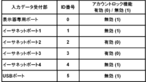
- FIG. 13 is a diagram showing the screen layout of a condition setting screen.
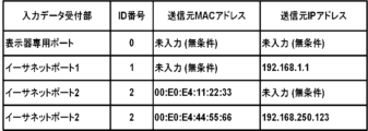
- FIG. 13 is a diagram showing the screen layout of a condition setting screen.
- FIG. 2 is a hardware configuration diagram of a control device.
- FIG. 1 is a block diagram showing the configuration of the control device 100.
- the control device 100 includes an input data receiving unit 11, a user authentication unit 12, a condition setting unit 13, a storage unit 14, and a judgment unit 15.
- the input data receiving unit 11 is a physical data input/output port.
- Physical data input/output ports include not only terminal sockets but also non-contact input/output ports such as short-range wireless communication.
- Physical sockets include USB ports and LAN ports.
- the input data receiving unit 11 is a physical interface that relays data exchange between the control device 100 and devices.
- the user authentication unit 12 identifies whether the user who has requested access is the actual user.
- the user authentication unit 12 requests "proof of identity (called authentication information)" from a communication partner (called a user: including a person, computer, or terminal) whose identity is unknown.
- the communication partner transmits the requested authentication information.
- the user authentication unit 12 verifies that the authentication information is correct and determines that the communication partner is the person in question, and then the authentication is completed. When the authentication is completed, the communication partner can access the control device 100 or a network managed by the control device 100.
- the type of authentication information is not particularly limited. Examples of the types of authentication information include codes such as a user name and a password, memory such as an IC card, and biometric information such as a fingerprint or a retina. There are also multi-factor authentication information that combines these types of authentication information.
- the user authentication unit 12 has an account lock function that prevents attacks from malicious third parties.
- the account lock function is a function that locks the account of a communication partner that is determined to be suspicious. A locked account cannot log in to the control device 100. To log in to the control device 100, the account lock must be released.
- the control device 100 of the present disclosure has a function for disabling account locking. Specifically, when the user authentication unit 12 receives an access request from an account that is locked but has correct authentication information, it queries the determination unit 15 as to whether the account lock is enabled/disabled. The determination unit 15 determines whether the account lock is enabled/disabled and responds to the user authentication unit 12. If the user authentication unit 12 determines that the account lock is disabled, it allows the user to log in. If the account lock is determined to be enabled, it denies the user from logging in.
- Account locking may be temporarily disabled. When temporarily disabled, even if the account locking is determined to be disabled once, the temporary disabled state will end at the next authentication. Therefore, it is necessary to determine whether the account locking is enabled or disabled each time authentication is performed.
- the condition setting unit 13 accepts the setting of conditions for enabling or disabling account locking or changes to the settings.
- the conditions are set by a user with setting authority (called a condition manager).
- the storage unit 14 stores the conditions. Rather than setting the conditions from scratch, default conditions may be set in the control device 100 and the condition manager may edit the conditions that have already been set.
- the judgment unit 15 When the judgment unit 15 receives an inquiry from the user authentication unit 12 about whether the account lock is enabled or disabled, it reads the conditions from the storage unit 14, obtains judgment information for checking the conditions, and checks whether the judgment information satisfies the conditions. If the judgment information satisfies the conditions, the judgment unit 15 responds to the user authentication unit 12 that the account lock is disabled.
- Determination information input data receiving unit that receives data from a device requesting access
- the determination information in the example of (1) is identification information of the input data receiving unit 11.
- the control device 100 is provided with a data input/output (input data receiving unit 11).
- a condition is set in which the input data receiving unit 11 and the account lock function of the device connected thereto are enabled or disabled.
- 2 shows an example of a condition setting screen.
- the setting screen displays a list of the input data receiving units 11. Specifically, "Display dedicated port”, "Ethernet port 1", “Ethernet port 2", “Ethernet port 3", "Ethernet port 4", and "USB port” are displayed.
- the condition setting unit 13 assigns ID numbers to conditions (input data receiving unit 11).
- the display-only port is assigned ID number "0”
- Ethernet port 1 is assigned ID number "1”
- Ethernet port 2 is assigned ID number "2”
- Ethernet port 3 is assigned ID number "3”
- Ethernet port 4 is assigned ID number "4"
- the USB port is assigned ID number "5".
- the condition setting unit 13 accepts the setting of enable (0) or disable (1) of the account lock function for the ID number.
- the "display dedicated port” with ID number "0” is assigned “disable (1)”
- the "Ethernet port 1" with ID number “1” is assigned “disable (1)”
- the "Ethernet port 2" with ID number “2” is assigned “enable (0)”
- the "Ethernet port 3" with ID number "3” is assigned “enable (0)”
- the "Ethernet port 4" with ID number "4" is assigned “disable (1)”
- the "USB port” with ID number "5" is assigned “disable (1)”.
- the judgment information in case (1) is the identification information of the input data receiving unit 11. Assume that device A is connected to the control device 100 via the input data receiving unit 11, and that device A transmits an access request to the control device 100.
- the judgment unit 15 acquires, as judgment information, the identification information of the input data receiving unit 11 that relays between device A and the control device 100.
- the judgment unit 15 judges whether the account lock is enabled or disabled based on the identification information of the input data receiving unit 11 and the conditions.
- the account lock for the "display dedicated port” is set to disabled.
- the operation monitor of the control device 100 is usually connected to the "display dedicated port.”
- the operation monitor is operated by a worker in the factory, so there is a low possibility of access from outside. Even if an account is in a locked state, the judgment unit 15 judges that the account lock is disabled if the access is from an operation monitor (connected to the "display dedicated port").
- the condition manager sets whether to enable or disable the account lock based on the network wiring, etc. For example, enabling the account lock for an entrance/exit that may be subject to intrusion from the outside, such as a router, can prevent intrusion from the outside. Also, disabling the account lock for an entrance/exit to which devices related to work inside the factory (operation monitors, pendants, etc.) are connected can prevent work inside the factory from being interrupted by the account lock. There is a low possibility of unauthorized access by workers inside the factory.
- the control device 100 of this embodiment can restrict access from outside without interrupting work inside the factory by setting a condition for enabling/disabling account locking in the input data receiving unit 11.
- the determination information in the example of (2) is the identification information of the input data acceptor 11, the source MAC address, and the source IP address.
- the MAC address is a physical number assigned to a network device such as a personal computer, a router, etc.
- the MAC address makes it possible to uniquely identify a source device (a device that transmits data to the control device 100 via the input data receiving unit 11).
- An IP address is a logical number assigned to a network device, and the IP address makes it possible to uniquely identify a source device (a device that transmits data to the control device 100 via an input data receiving unit).
- the condition setting unit 13 sets the conditions (combination of input data receiving unit 11, source MAC address, and source IP address).
- the first combination (first row of the table) is set to input data receiving unit "Display dedicated port”, source MAC address "Not entered (unconditional)", and source IP address "Not entered (unconditional)”.
- the second combination (second row of the table) is set to input data receiving unit "Ethernet port 1", source MAC address "Not entered (unconditional)", and source IP address "192.168.1.1".
- the third combination (third row of the table) is set to an input data reception section "Ethernet port 2", a source MAC address "00:E0:E4:11:22:33”, and a source IP address "not entered (unconditional)".
- the fourth combination (fourth row of the table) is set to an input data reception section "Ethernet port 2", a source MAC address "00:E0:E4:44:55:66", and a source IP address "192.168.250.123".
- the number of lines for the setting items in Figure 3 is four, but it is possible to add or delete lines.
- the setting screen may be provided with an [Add] button, a [Delete] button, or a similar function.
- a first combination of conditions is an input data receiving unit "display dedicated port.” If a device that has sent an access request to the control device 100 is connected to the "display dedicated port,” the account locking of the device connected to the "display dedicated port” is disabled regardless of the source MAC address and source IP address.
- the second combination of conditions when the input data receiving unit is "Ethernet port 1" and the source IP address is "192.168.1.1", the account lock is disabled.
- the condition that the terminal to which the IP address "192.168.1.1” of the administrator is set is connected to "Ethernet port 1"
- the account lock is disabled.
- the account lock is disabled. In other words, when the condition that a terminal having a network board with a source MAC address of "00:E0:E4:11:22:33" is connected to "Ethernet port 2" is satisfied, the account lock is disabled.
- the fourth combination of conditions if the input data reception unit is "Ethernet port 2", the source MAC address is "00:E0:E4:44:55:66", and the source IP address is "192.168.250.123", the account lock is disabled.
- IP address "192.168.250.123” is set to a terminal having a network board with a source MAC address of "00:E0:E4:44:55:66", and the terminal is connected to "Ethernet port 2", the account lock is disabled.
- the MAC address and IP address can be obtained from the packet header.
- the judgment unit 15 can automatically select packets that satisfy the judgment conditions based on the MAC address and IP address read from the packet.
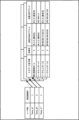
- FIG. 4 is a schematic diagram of conditions set for each user.
- User ID "User_A” is linked to setting screen ID "1”
- user ID "User_B” is linked to setting screen ID "2”
- user ID "User_C” is linked to setting screen ID "3”. If the number of user IDs is N, combinations of N user IDs and setting screen data are stored in the storage unit 14.
- the judgment unit 15 identifies the user from the authentication information and reads out the conditions linked to the user ID. Examples of the conditions have already been explained in (1) and (2).
- the judgment unit 15 identifies the user from the authentication information and judges whether the account lock is enabled or disabled based on the conditions linked to the user.
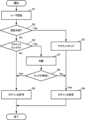
- the operation of the control device 100 of this embodiment will be described with reference to the flowchart in Figure 5.
- the user authentication unit 12 acquires authentication information and performs user authentication (step S1). If authentication fails (step S2; Yes), the user authentication unit 12 locks the account (step S3) and denies the user login (step S4). There are no particular limitations on the conditions for locking an account. For example, an account that has failed authentication a certain number of times in a row may be locked.
- step S2 If authentication is successful (step S2; No), the user authentication unit 12 judges whether the account is locked or not. If the account is not locked (step S5; No), the user authentication unit 12 allows the user to log in (step S6). If the account is locked (step S5; Yes), the user authentication unit 12 queries the judgment unit 15.
- the judgment unit 15 acquires the judgment information and judges whether the account lock is invalid (step S7). Specifically, it judges whether the judgment information satisfies the conditions such as (1), (2), and (3) described above.
- the user authentication unit 12 receives a response from the judgment unit 15. If the response indicates that the account lock is invalid (step S8; Yes), the user authentication unit 12 allows the user to log in (step S6). If the response indicates that the account lock is valid (step S8; No), the user authentication unit 12 denies the user from logging in (step S4).
- control device 100 of this embodiment stores the conditions for determining whether an account lock is enabled or disabled, and when an access request is received from a locked account, it obtains judgment information that serves as the basis for judgment, and if the judgment information meets the conditions, it disables the account lock and allows login.
- the main condition is the input data receiving unit 11, which is the data input/output port of the control device 100. Which input data receiving unit 11 acted as a relay and input data is used as judgment information to determine whether or not to disable the account lock of the device connected to the input data receiving unit 11.
- IP address which is an address on the network
- MAC address which is information unique to the device.
- Other conditions can also be linked to the user's identification information. This allows you to set different conditions for each user. For example, if a user has a specific device they use, you can set it so that account locking is disabled only for access from that device.
- the conditions for locking an account may be hard-coded into the program.
- the program may also be configured to accept edits to the hard-coded default settings. For example, edits may be made to add conditions such as MAC addresses, IP addresses, and user identification information.
- the input data reception unit 11 is the physical data inlet/outlet, but the physical data inlet/outlet may also include a wireless terminal that can be used only within a factory, such as a short-range wireless terminal. Also, the type of physical inlet/outlet is not limited.
- FIG. 6 is a hardware configuration diagram of the control device 100.
- the control device 100 includes a CPU 111 that controls the entire control device 100, a ROM 112 that records programs and data, and a RAM 113 for temporarily expanding data.
- the CPU 111 reads out the system program recorded in the ROM 112 via the bus and executes the avoidance in accordance with the system program.
- the non-volatile memory 114 retains its stored state even when the control device 100 is powered off, for example by being backed up by a battery (not shown).
- Various data are stored in the non-volatile memory 114, such as programs read from the external device 120 via the interfaces 115, 118, and 119, and operation inputs entered via the input unit 30.
- the non-volatile memory 114 may also store programs and data for executing the control device 100 of this embodiment.
- the display unit 70 displays various data, measurement results, causes of invalid data, and the like.
- the interface 115 is an interface for connecting the control device 100 to an external device 120 such as an adapter. Programs, various parameters, and the like are read from the external device 120.
- the interface 118 is an interface for connecting the control device 100 to a display unit 70 such as a liquid crystal display. The display unit 70 displays various data loaded into the memory, data obtained as a result of executing a program, and the like.
- the interface 119 is an interface for connecting the control device 100 to an input unit 30 such as a keyboard, a pointing device, etc. The input unit 30 passes instructions, data, etc. based on operations by an operator to the CPU 111 via the interface 119.
- the control device (100) comprises an input data receiving unit (11) which is a physical data input/output port, a user authentication unit (12) which acquires user authentication information and locks the account of a user who has failed authentication, a memory unit (14) which stores conditions for disabling the account lock, and a judgment unit (15) which judges whether or not to disable the account lock of a device that has sent a new access request using the account-locked account based on the conditions, using the input data receiving unit which inputs data from the device as judgment information.
- the user authentication unit (12) temporarily disables the account lock.
- the control device (100) includes a condition setting unit (13) that accepts changes to the conditions.
- the judgment information is a combination of at least one of a MAC address and an IP address of the device that has sent the access request and the input data receiving unit (11).
- the determination unit If the data input from the device that transmitted the access request is an Ethernet packet, the determination unit (15) obtains the MAC address and IP address contained in the Ethernet packet as determination conditions.
- the determination information includes identification information of the user.
- a computer-readable storage medium (112, 113, 114) stores instructions to cause one or more processors (111) to execute processing to acquire user authentication information, lock the account of a user who has failed authentication, and, upon receiving a new access request using the locked account, determine whether or not to disable the account lock based on preset conditions, using an input data receiving unit, which is a physical input/output port for data from a device that sent the new access request, as judgment information.
- Control device 11 Input data receiving unit 12
- User authentication unit 13 Condition setting unit 14
- Storage unit 15 Determination unit 111
Landscapes
- Engineering & Computer Science (AREA)
- Computer Security & Cryptography (AREA)
- Theoretical Computer Science (AREA)
- Computer Hardware Design (AREA)
- Software Systems (AREA)
- Physics & Mathematics (AREA)
- General Engineering & Computer Science (AREA)
- General Physics & Mathematics (AREA)
- Small-Scale Networks (AREA)
Abstract
制御装置は、ユーザの認証情報を取得し、認証に失敗したユーザのアカウントにアカウントロックをかけ、前記アカウントロックされたユーザと同じアカウントを使用した新たなアクセス要求を受けると、前記新たなアクセス要求を送信した機器からのデータの物理的な入出口である入力データ受付部を判断情報として、事前に設定された条件を基に、前記アカウントロックを無効にするか否かを判断する。
Description
本開示は、制御装置、及びコンピュータが読み取り可能な記憶媒体に関する。
近年、工場とコンピュータネットワークとを接続したスマート工場が存在する。スマート工場では、センサやアクチュエータなどの下層の機器と外部のネットワークとを、PLC(Programmable Logic Controller)や数値制御装置などの制御装置が中継する。
制御装置は、ユーザ認証機能を備え、外部からの自由なアクセスを防止する。ユーザ認証は、悪意ある第三者から攻撃されることがある。総当たり攻撃(Brute-force attack)は、攻撃の1つである。総当たり攻撃では、IDとパスワードなどの認証情報を模倣した符号列を自動的に生成し、正しい認証情報と一致するまで符号列を入力する。総当たり攻撃を防止する方法として、認証情報の入力の回数に制限を設け、一定の回数連続で誤った情報が入力された場合、疑わしいアカウントをロックする方法がある。例えば、特許文献1参照。
アカウントがロックされると、ユーザは、管理者に依頼してロックを解除してもらったり、ロックが自動的に解除されるまで規定時間待機したりする必要がある。ユーザが工場の作業者の場合、制御装置を操作できなくなり、産業機械の生産性が低下するおそれがある。
工場のネットワーク管理の分野では、安全性と可用性を確保することが望まれている。
本開示の一態様である制御装置は、物理的なデータの入出口である入力データ受付部と、ユーザの認証情報を取得し、認証に失敗したユーザのアカウントにアカウントロックをかけるユーザ認証部と、前記アカウントロックを無効にする条件を記憶する記憶部と、前記アカウントロックされたアカウントを使用して新たなアクセス要求を送信した機器のアカウントロックを無効にするか否かを、前記機器からのデータを入力する入力データ受付部を判断情報として、前記条件を基に判断する判断部と、を備える。
以下、図面を参照して本実施形態の制御装置100について説明する。図1は、制御装置100の構成を示すブロック図である。制御装置100は、入力データ受付部11、ユーザ認証部12、条件設定部13、記憶部14、判断部15を備える。
入力データ受付部11は、物理的なデータの入出口である。物理的なデータの入出口には、端子の差込口だけでなく、近距離無線通信などの非接触の入出口も含む。物理的な差込口には、USBポート、LANポートなどがある。入力データ受付部11は、制御装置100と機器との間データのやりとりを中継する、物理的なインタフェースである。
ユーザ認証部12は、アクセスを要求したユーザが、本人であるかを識別する。ユーザ認証部12は、本人であるかどうかが不明な通信相手(ユーザとよぶ:人、コンピュータ、端末を含む)に対して「本人である証拠(認証情報とよぶ)」を要求する。
通信相手は、要求される認証情報を送信する。ユーザ認証部12は、認証情報が正しいことを確認し、通信相手が本人であると判定すると、認証が完了する。認証が完了すると、通信相手は、制御装置100又は制御装置100が管理するネットワークにアクセスできる。
なお、認証情報の種類は、特に限定しない。認証情報の種類には、例えば、ユーザ名とパスワードなどの符号、ICカードなどのメモリ、指紋や網膜などの生体情報がある。これらの認証情報を組み合わせた多要素もある。
通信相手は、要求される認証情報を送信する。ユーザ認証部12は、認証情報が正しいことを確認し、通信相手が本人であると判定すると、認証が完了する。認証が完了すると、通信相手は、制御装置100又は制御装置100が管理するネットワークにアクセスできる。
なお、認証情報の種類は、特に限定しない。認証情報の種類には、例えば、ユーザ名とパスワードなどの符号、ICカードなどのメモリ、指紋や網膜などの生体情報がある。これらの認証情報を組み合わせた多要素もある。
ユーザ認証部12は、悪意ある第三者からの攻撃を防ぐアカウントロック機能を有する。アカウントロック機能とは、疑わしいと判断された通信相手のアカウントをロックする機能である。ロックされたアカウントは、制御装置100にログインすることができない。制御装置100にログインするためには、アカウントロックを解除する必要がある。
本開示の制御装置100は、アカウントロックを無効にする機能を備える。具体的には、ユーザ認証部12は、認証情報は正しいがロックされたアカウントからアクセス要求を受けると、アカウントロックが有効/無効かを判断部15に問い合わせる。判断部15は、アカウントロックの有効/無効を判断してユーザ認証部12に応答する。ユーザ認証部12は、アカウントロックが無効であると判断された場合、当該ユーザのログインを許可する。アカウントロックが有効であると判断された場合、当該ユーザのログインを拒否する。
アカウントロックは、一時的に無効にしてもよい。一時的に無効にする場合、一度アカウントロックが無効であると判断しても、次の認証時には一時的な無効状態が終了する。そのため、認証の度に有効/無効の判断が必要である。
条件設定部13は、アカウントロックを有効又は無効にする条件の設定ないしは設定の変更を受け付ける。条件の設定は、設定権限を有するユーザ(条件管理者とよぶ)が行う。記憶部14は、条件を記憶する。条件は、最初から設定するのではなく、デフォルトの条件を制御装置100に設定しておき、既に設定された条件を条件管理者が編集するようにしてもよい。
判断部15は、ユーザ認証部12からアカウントロックの有効/無効の問い合わせを受けると、記憶部14から条件を読み出し、条件を確認するための判断情報を取得し、判断情報が条件を満たすかどうかを確認する。判断情報が条件を満たす場合、判断部15は、アカウントロックが無効である旨をユーザ認証部12に応答する。
以下、判断情報と条件の例を3つ説明する。
(1)判断情報:アクセスを要求する機器からのデータを入力する入力データ受付部
(1)の例における判断情報は、入力データ受付部11の識別情報である。制御装置100には、データの入出口(入力データ受付部11)が設けられている。(1)の条件では、入力データ受付部11と、そこに接続された機器のアカウントロック機能が有効か無効という条件が設定される。
図2は、条件の設定画面の一例を示す。設定画面には、入力データ受付部11が一覧表示されている。具体的には、「表示器専用ポート」、「イーサネットポート1」、「イーサネットポート2」、「イーサネットポート3」、「イーサネットポート4」、「USBポート」が表示されている。
(1)判断情報:アクセスを要求する機器からのデータを入力する入力データ受付部
(1)の例における判断情報は、入力データ受付部11の識別情報である。制御装置100には、データの入出口(入力データ受付部11)が設けられている。(1)の条件では、入力データ受付部11と、そこに接続された機器のアカウントロック機能が有効か無効という条件が設定される。
図2は、条件の設定画面の一例を示す。設定画面には、入力データ受付部11が一覧表示されている。具体的には、「表示器専用ポート」、「イーサネットポート1」、「イーサネットポート2」、「イーサネットポート3」、「イーサネットポート4」、「USBポート」が表示されている。
条件設定部13は、条件(入力データ受付部11)にID番号を割り当てる。図2の例では、表示器専用ポートにID番号「0」、「イーサネットポート1」にID番号「1」、「イーサネットポート2」にID番号「2」、「イーサネットポート3」にID番号「3」、「イーサネットポート4」にID番号「4」、「USBポート」にID番号「5」が割り当てられている。
条件設定部13は、ID番号に対するアカウントロック機能の有効(0)、無効(1)の設定を受け付ける。図2の例では、ID番号「0」の「表示器専用ポート」には「無効(1)」、ID番号「1」の「イーサネットポート1」には「無効(1)」、ID番号「2」の「イーサネットポート2」には「有効(0)」、ID番号「3」の「イーサネットポート3」には「有効(0)」、ID番号「4」の「イーサネットポート4」には「無効(1)」、ID番号「5」の「USBポート」には「無効(1)」が割り当てられている。
(1)の場合の判断情報は、入力データ受付部11の識別情報である。機器Aが入力データ受付部11を介して制御装置100に接続されており、機器Aから制御装置100にアクセス要求を送信したとする。判断部15は、機器Aと制御装置100とを中継する入力データ受付部11の識別情報を、判断情報として取得する。判断部15は、入力データ受付部11の識別情報と、条件とを基にアカウントロックの有効/無効を判断する。
条件について具体的に説明する。図2の条件の1行目では、「表示器専用ポート」のアカウントロックが無効と設定されている。「表示器専用ポート」には、通常、制御装置100の操作モニタが接続される。操作モニタは、工場の作業者が操作するため、外部からのアクセスである可能性は低い。判断部15は、あるアカウントがロック状態であったとしても、そのアカウントが(「表示器専用ポート」に接続された)操作モニタからのアクセスであればアカウントロックは無効であると判断する。
条件管理者は、ネットワークの配線などを基に、アカウントロックの有効/無効を設定する。例えば、ルータなど外部からの侵入のおそれのある入出口のアカウントロックを有効にすると、外部からの侵入を防止することができる。また、工場内部での作業にかかわる機器(操作モニタ、ペンダントなど)が接続された入出口のアカウントロックを無効にすると、アカウントロックによる工場内部での作業の中断を防止することができる。
工場内部の作業者は、不正なアクセスである可能性が低い。本実施形態の制御装置100は、入力データ受付部11に対し、アカウントロックの有効/無効の条件を設定することにより、工場の内部での作業を中断することなく、外部からのアクセスを制限することができる。
工場内部の作業者は、不正なアクセスである可能性が低い。本実施形態の制御装置100は、入力データ受付部11に対し、アカウントロックの有効/無効の条件を設定することにより、工場の内部での作業を中断することなく、外部からのアクセスを制限することができる。
(2)判断情報:入力データ受付部11の識別情報、MACアドレス、IPアドレス
(2)の例における判断情報は、入力データ受付部11の識別情報、送信元MACアドレス、送信元IPアドレスである。
MACアドレスは、パソコンやルータなどのネットワーク機器に対して割り当てられた物理的な番号である。MACアドレスにより、送信元の機器(入力データ受付部11を介して制御装置100にデータを送信する機器)を一意に識別できる。
IPアドレスは、ネットワーク機器に対して割り当てられた論理的な番号である。IPアドレスにより、送信元の機器(入力データ受付部を介して制御装置100にデータを送信する機器)を一意に識別できる。
(2)の例における判断情報は、入力データ受付部11の識別情報、送信元MACアドレス、送信元IPアドレスである。
MACアドレスは、パソコンやルータなどのネットワーク機器に対して割り当てられた物理的な番号である。MACアドレスにより、送信元の機器(入力データ受付部11を介して制御装置100にデータを送信する機器)を一意に識別できる。
IPアドレスは、ネットワーク機器に対して割り当てられた論理的な番号である。IPアドレスにより、送信元の機器(入力データ受付部を介して制御装置100にデータを送信する機器)を一意に識別できる。
条件設定部13は、条件(入力データ受付部11、送信元MACアドレス、送信元IPアドレスの組み合わせ)を設定する。図3の例では、第1の組み合わせ(表の1行目)として、入力データ受付部「表示器専用ポート」、送信元MACアドレス「未入力(無条件)」、送信元IPアドレス「未入力(無条件)」が設定されている。第2の組み合わせ(表の2行目)として、入力データ受付部「イーサネットポート1」、送信元MACアドレス「未入力(無条件)」、送信元IPアドレス「192.168.1.1」が設定されている。第3の組み合わせ(表の3行目)として、入力データ受付部「イーサネットポート2」、送信元MACアドレス「00:E0:E4:11:22:33」、送信元IPアドレス「未入力(無条件)」、第4の組み合わせとして(表の4行目)、入力データ受付部「イーサネットポート2」、送信元MACアドレス「00:E0:E4:44:55:66」、送信元IPアドレス「192.168.250.123」が設定されている。
図3の設定項目の行数は4行であるが、追加/削除することもできる。設定画面には[追加]ボタン、[削除]ボタン、又はそれに類似する機能を備えてもよい。
図3の例は、アカウントロックを無効にする条件のリストとする。例えば、第1の組み合わせの条件は、入力データ受付部「表示器専用ポート」である。制御装置100にアクセス要求を送信した機器が「表示器専用ポート」に接続されていれば、送信元MACアドレス及び送信元IPに関わらず、「表示器専用ポート」に接続された機器のアカウントロックは無効である。
第2の組み合わせの条件では、入力データ受付部「イーサネットポート1」、送信元IPアドレス「192.168.1.1」という条件を満たす場合、アカウントロックが無効になる。すなわち、管理者(システムの管理者であって条件管理者とは異なる)のIPアドレス「192.168.1.1」が設定された端末が、「イーサネットポート1」に接続されたという条件を満たした場合、アカウントロックが無効になる。
第3の組み合わせの条件では、入力データ受付部「イーサネットポート2」、送信元MACアドレス「00:E0:E4:11:22:33」という条件を満たす場合、アカウントロックが無効になる。すなわち、送信元MACアドレス「00:E0:E4:11:22:33」のネットワークボードを有する端末が「イーサネットポート2」に接続されたという条件を満たした場合、アカウントロックが無効になる。
第4の組み合わせの条件では、入力データ受付部「イーサネットポート2」、送信元MACアドレス「00:E0:E4:44:55:66」、送信元IPアドレス「192.168.250.123」という条件を満たす場合、アカウントロックが無効になる。すなわち、送信元MACアドレス「00:E0:E4:44:55:66」のネットワークボードを有する端末には、IPアドレス「192.168.250.123」が設定されており、当該端末が「イーサネットポート2」に接続されているという条件を満たした場合、アカウントロックが無効になる。
第2の組み合わせの条件では、入力データ受付部「イーサネットポート1」、送信元IPアドレス「192.168.1.1」という条件を満たす場合、アカウントロックが無効になる。すなわち、管理者(システムの管理者であって条件管理者とは異なる)のIPアドレス「192.168.1.1」が設定された端末が、「イーサネットポート1」に接続されたという条件を満たした場合、アカウントロックが無効になる。
第3の組み合わせの条件では、入力データ受付部「イーサネットポート2」、送信元MACアドレス「00:E0:E4:11:22:33」という条件を満たす場合、アカウントロックが無効になる。すなわち、送信元MACアドレス「00:E0:E4:11:22:33」のネットワークボードを有する端末が「イーサネットポート2」に接続されたという条件を満たした場合、アカウントロックが無効になる。
第4の組み合わせの条件では、入力データ受付部「イーサネットポート2」、送信元MACアドレス「00:E0:E4:44:55:66」、送信元IPアドレス「192.168.250.123」という条件を満たす場合、アカウントロックが無効になる。すなわち、送信元MACアドレス「00:E0:E4:44:55:66」のネットワークボードを有する端末には、IPアドレス「192.168.250.123」が設定されており、当該端末が「イーサネットポート2」に接続されているという条件を満たした場合、アカウントロックが無効になる。
なお、図3の例では、1つの「イーサネットポート2」に2つの条件が設定されている。このように、1つの物理的な接続口に複数の条件を設定することができる。
MACアドレス及びIPアドレスは、パケットのヘッダから取得できる。判断部15は、パケットから読み出したMACアドレス及びIPアドレスを判断条件として、条件を満たすパケットを自動的に選択できる。
(3)ユーザと条件を紐づける
(3)の例では、ユーザごとに条件を設定する。図4は、ユーザごとに設定した条件の模式図である。ユーザID「User_A」は設定画面ID「1」、ユーザID「User_B」は設定画面ID「2」、ユーザID「User_C」は設定画面ID「3」に紐づけられている。ユーザIDの数をNとすると、N個のユーザIDと設定画面のデータの組み合わせを記憶部14に保存する。
(3)の例では、ユーザごとに条件を設定する。図4は、ユーザごとに設定した条件の模式図である。ユーザID「User_A」は設定画面ID「1」、ユーザID「User_B」は設定画面ID「2」、ユーザID「User_C」は設定画面ID「3」に紐づけられている。ユーザIDの数をNとすると、N個のユーザIDと設定画面のデータの組み合わせを記憶部14に保存する。
判断部15は、認証情報からユーザを特定し、ユーザIDに紐づけられた条件を読み出す。条件の例は、(1)、(2)で既に説明した。判断部15は、認証情報からユーザを特定し、ユーザに紐づけられた条件を基に、アカウントロックの有効/無効を判断する。
図5のフローチャートを参照して本実施形態の制御装置100の動作を説明する。ユーザ認証部12は、認証情報を取得し、ユーザ認証を行う(ステップS1)。認証に失敗すると(ステップS2;Yes)、ユーザ認証部12は、アカウントをロックして(ステップS3)、ユーザのログインを拒否する(ステップS4)。アカウントをロックする条件は、特に限定しない。例えば、認証に一定の回数連続で失敗したアカウントをロックする。
認証に成功すると(ステップS2;No)、ユーザ認証部12は、アカウントがロックされているか否かを判断する。アカウントがロックされていない場合(ステップS5;No)、ユーザ認証部12は、ユーザのログインを許可する(ステップS6)。アカウントがロックされている場合(ステップS5;Yes)、ユーザ認証部12は、判断部15に問い合わせを行う。
判断部15は、判断情報を取得し、アカウントロックが無効であるか否かを判断する(ステップS7)。具体的には、上述した(1)、(2)、(3)のような条件を基に、判断情報が条件を満たすか判断する。
ユーザ認証部12は、判断部15からの応答を取得する。アカウントロックが無効と応答された場合(ステップS8;Yes)、ユーザ認証部12は、ユーザのログインを許可する(ステップS6)。アカウントロックが有効と応答された場合(ステップS8;No)、ユーザ認証部12は、ユーザのログインを拒否する(ステップS4)。
以上説明したように、本実施形態の制御装置100は、アカウントロックの有効/無効を判断するための条件を記憶し、ロックがかかったアカウントからのアクセス要求を受けたとき、判断の基準となる判断情報を取得し、判断情報が条件を満たす場合には、アカウントロックを無効にし、ログインを許可する。
主な条件は、制御装置100のデータの入出口である入力データ受付部11である。どの入力データ受付部11が中継となりデータを入力したかを判断情報として、入力データ受付部11に接続された機器のアカウントロックを無効にするか否かを判断する。
他の条件として、ネットワーク上の住所であるIPアドレス、及び機器の固有情報であるMACアドレスの組み合わせがある。IPアドレスとMACアドレスを組み合わせることにより、機器を特定することができる。特定の機器にのみアクセスを許可することで安全性が向上する。
他の条件として、ユーザの識別情報を紐づけることもできる。これにより、ユーザごとに異なる条件を設定できる。例えば、ユーザが使用する機器が決まっているのであれば、その機器からのアクセスのみアカウントロックを無効にするという設定ができる。
アカウントロックの条件は、プログラムにハードコーディングしてもよい。また、ハードコーディングしたデフォルトの設定に対する編集を受け付けるような構成にしてもよい。例えば、編集により、MACアドレス、IPアドレス、ユーザの識別情報などの条件を追加してもよい。
なお、本実施の形態では、入力データ受付部11を物理的なデータの入出口としたが、近距離無線のような工場内でのみ使用可能な無線端末を物理的なデータの入出口に含めてもよい。また、物理的な入出口の種類は限定しない。
従来のアカウントロックでは、アカウントをロックされたユーザは、アカウントロックが解除されるまで制御装置100を操作できず、作業を開始できない。本実施形態の制御装置100では、予め登録された条件を満たせば、アカウントロックを無効し、作業の中断を回避する。これにより安全性と可用性を確保することができる。
以下、本開示を適用し制御装置100のハードウェア構成について説明する。図6は、制御装置100のハードウェア構成図である。制御装置100は、図6に示すように、制御装置100を全体的に制御するCPU111、プログラムやデータを記録するROM112、一時的にデータを展開するためのRAM113を備え、CPU111はバスを介してROM112に記録されたシステムプログラムを読み出し、システムプログラムに従って回避を実行する。
不揮発性メモリ114は、例えば、図示しないバッテリでバックアップされるなどして、制御装置100の電源がオフされても記憶状態が保持される。不揮発性メモリ114には、インタフェース115、118、119を介して外部装置120から読み込まれたプログラムや入力部30を介して入力された操作入力などの各種データが記憶される。不揮発性メモリ114に、本実施形態の制御装置100を実行するためのプログラムおよびデータを記憶してもよい。また、表示部70には各種データ、測定結果、不正なデータの要因などが表示される。
インタフェース115は、制御装置100とアダプタ等の外部装置120と接続するためのインタフェースである。外部装置120側からはプログラムや各種パラメータ等が読み込まれる。
インタフェース118は、制御装置100と液晶ディスプレイ等の表示部70とを接続するためのインタフェースである。表示部70には、メモリ上に読み込まれた各データ、プログラム等が実行された結果として得られたデータ等が表示される。
インタフェース119は、制御装置100とキーボード、ポインティングデバイス等の入力部30とを接続するためのインタフェースである。入力部30は、オペレータによる操作に基づく指令、データ等を、インタフェース119を介してCPU111に渡す。
インタフェース118は、制御装置100と液晶ディスプレイ等の表示部70とを接続するためのインタフェースである。表示部70には、メモリ上に読み込まれた各データ、プログラム等が実行された結果として得られたデータ等が表示される。
インタフェース119は、制御装置100とキーボード、ポインティングデバイス等の入力部30とを接続するためのインタフェースである。入力部30は、オペレータによる操作に基づく指令、データ等を、インタフェース119を介してCPU111に渡す。
本開示について詳述したが、本開示は上述した個々の実施形態に限定されるものではない。これらの実施形態は、本開示の要旨を逸脱しない範囲で、又は、請求の範囲に記載された内容とその均等物から導き出される本開示の主旨を逸脱しない範囲で種々の追加、置き換え、変更、部分的削除等が可能である。また、これらの実施形態は、組合せて実施することもできる。例えば、上述した実施形態において、各動作の順序や各処理の順序は、一例として示したものであり、これらに限定されるものではない。
上記実施形態及び変形例に関し、更に以下の付記を開示する。
(付記1)
制御装置(100)は、物理的なデータの入出口である入力データ受付部(11)と、ユーザの認証情報を取得し、認証に失敗したユーザのアカウントにアカウントロックをかけるユーザ認証部(12)と、前記アカウントロックを無効にする条件を記憶する記憶部(14)と、前記アカウントロックされたアカウントを使用して新たなアクセス要求を送信した機器のアカウントロックを無効にするか否かを、前記機器からのデータを入力する入力データ受付部を判断情報として、前記条件を基に判断する判断部(15)と、を備える。
(付記2)
前記ユーザ認証部(12)は、前記アカウントロックを一時的に無効にする。
(付記3)
制御装置(100)は、前記条件の変更を受け付ける条件設定部(13)を備える。
(付記4)
前記判断情報は、前記アクセス要求を送信した機器のMACアドレス又はIPアドレスの少なくとも一方と、前記入力データ受付部(11)との組み合わせである。
(付記5)
前記アクセス要求を送信した機器から入力したデータがイーサネットパケットである場合、前記判断部(15)は、前記イーサネットパケットに含まれるMACアドレス及びIPアドレスを判断条件として取得する。
(付記6)
前記判断情報は、ユーザの識別情報を含む。
(付記7)
コンピュータが読み取り可能な記憶媒体(112、113、114)は、1つ又は複数のプロセッサ(111)に、ユーザの認証情報を取得し、認証に失敗したユーザのアカウントにアカウントロックをかけ、前記アカウントロックされたアカウントを使用した新たなアクセス要求を受けると、前記新たなアクセス要求を送信した機器からのデータの物理的な入出口である入力データ受付部を判断情報として、事前に設定された条件を基に、前記アカウントロックを無効にするか否かを判断する、処理を実行させる命令を記憶する。
(付記1)
制御装置(100)は、物理的なデータの入出口である入力データ受付部(11)と、ユーザの認証情報を取得し、認証に失敗したユーザのアカウントにアカウントロックをかけるユーザ認証部(12)と、前記アカウントロックを無効にする条件を記憶する記憶部(14)と、前記アカウントロックされたアカウントを使用して新たなアクセス要求を送信した機器のアカウントロックを無効にするか否かを、前記機器からのデータを入力する入力データ受付部を判断情報として、前記条件を基に判断する判断部(15)と、を備える。
(付記2)
前記ユーザ認証部(12)は、前記アカウントロックを一時的に無効にする。
(付記3)
制御装置(100)は、前記条件の変更を受け付ける条件設定部(13)を備える。
(付記4)
前記判断情報は、前記アクセス要求を送信した機器のMACアドレス又はIPアドレスの少なくとも一方と、前記入力データ受付部(11)との組み合わせである。
(付記5)
前記アクセス要求を送信した機器から入力したデータがイーサネットパケットである場合、前記判断部(15)は、前記イーサネットパケットに含まれるMACアドレス及びIPアドレスを判断条件として取得する。
(付記6)
前記判断情報は、ユーザの識別情報を含む。
(付記7)
コンピュータが読み取り可能な記憶媒体(112、113、114)は、1つ又は複数のプロセッサ(111)に、ユーザの認証情報を取得し、認証に失敗したユーザのアカウントにアカウントロックをかけ、前記アカウントロックされたアカウントを使用した新たなアクセス要求を受けると、前記新たなアクセス要求を送信した機器からのデータの物理的な入出口である入力データ受付部を判断情報として、事前に設定された条件を基に、前記アカウントロックを無効にするか否かを判断する、処理を実行させる命令を記憶する。
100 制御装置
11 入力データ受付部
12 ユーザ認証部
13 条件設定部
14 記憶部
15 判断部
111 CPU
112 ROM
113 RAM
114 不揮発性メモリ
11 入力データ受付部
12 ユーザ認証部
13 条件設定部
14 記憶部
15 判断部
111 CPU
112 ROM
113 RAM
114 不揮発性メモリ
Claims (7)
- 物理的なデータの入出口である入力データ受付部と、
ユーザの認証情報を取得し、認証に失敗したユーザのアカウントにアカウントロックをかけるユーザ認証部と、
前記アカウントロックを無効にする条件を記憶する記憶部と、
アカウントロックされたアカウントを使用して新たなアクセス要求を送信した機器のアカウントロックを無効にするか否かを、前記機器からのデータを入力する入力データ受付部を判断情報として、前記条件を基に判断する判断部と、
を備える制御装置。 - 前記ユーザ認証部は、前記アカウントロックを一時的に無効にする、請求項1記載の制御装置。
- 前記条件の変更を受け付ける条件設定部を備える、請求項1記載の制御装置。
- 前記判断情報は、前記アクセス要求を送信した機器のMACアドレス又はIPアドレスの少なくとも一方と、前記入力データ受付部との組み合わせである、請求項1記載の制御装置。
- 前記アクセス要求を送信した機器から入力したデータがイーサネットパケットである場合、前記判断部は、前記イーサネットパケットに含まれるMACアドレス及びIPアドレスを判断条件として取得する、請求項4記載の制御装置。
- 前記判断情報にユーザの識別情報を含む、請求項1記載の制御装置。
- 1つ又は複数のプロセッサに、
ユーザの認証情報を取得し、認証に失敗したユーザのアカウントにアカウントロックをかけ、
前記アカウントロックされたアカウントを使用した新たなアクセス要求を受けると、前記新たなアクセス要求を送信した機器からのデータの物理的な入出口である入力データ受付部を判断情報として、事前に設定された条件を基に、前記アカウントロックを無効にするか否かを判断する、
処理を実行させる命令を記憶するコンピュータが読み取り可能な記憶媒体。
Priority Applications (2)
| Application Number | Priority Date | Filing Date | Title |
|---|---|---|---|
| PCT/JP2023/021607 WO2024252680A1 (ja) | 2023-06-09 | 2023-06-09 | 制御装置、及びコンピュータが読み取り可能な記憶媒体 |
| JP2025525921A JPWO2024252680A1 (ja) | 2023-06-09 | 2023-06-09 |
Applications Claiming Priority (1)
| Application Number | Priority Date | Filing Date | Title |
|---|---|---|---|
| PCT/JP2023/021607 WO2024252680A1 (ja) | 2023-06-09 | 2023-06-09 | 制御装置、及びコンピュータが読み取り可能な記憶媒体 |
Publications (1)
| Publication Number | Publication Date |
|---|---|
| WO2024252680A1 true WO2024252680A1 (ja) | 2024-12-12 |
Family
ID=93795834
Family Applications (1)
| Application Number | Title | Priority Date | Filing Date |
|---|---|---|---|
| PCT/JP2023/021607 Ceased WO2024252680A1 (ja) | 2023-06-09 | 2023-06-09 | 制御装置、及びコンピュータが読み取り可能な記憶媒体 |
Country Status (2)
| Country | Link |
|---|---|
| JP (1) | JPWO2024252680A1 (ja) |
| WO (1) | WO2024252680A1 (ja) |
Citations (3)
| Publication number | Priority date | Publication date | Assignee | Title |
|---|---|---|---|---|
| JP2006251857A (ja) * | 2005-03-08 | 2006-09-21 | Internatl Business Mach Corp <Ibm> | クライアントのi/oアクセスを制限する方法、プログラム、システム |
| JP2007141085A (ja) * | 2005-11-21 | 2007-06-07 | Fuji Xerox Co Ltd | コンピュータシステム、認証制御方法、プログラム及びサーバ・クライアントシステム |
| JP2008046867A (ja) * | 2006-08-16 | 2008-02-28 | Fuji Xerox Co Ltd | 認証制御プログラムおよび認証装置 |
-
2023
- 2023-06-09 JP JP2025525921A patent/JPWO2024252680A1/ja active Pending
- 2023-06-09 WO PCT/JP2023/021607 patent/WO2024252680A1/ja not_active Ceased
Patent Citations (3)
| Publication number | Priority date | Publication date | Assignee | Title |
|---|---|---|---|---|
| JP2006251857A (ja) * | 2005-03-08 | 2006-09-21 | Internatl Business Mach Corp <Ibm> | クライアントのi/oアクセスを制限する方法、プログラム、システム |
| JP2007141085A (ja) * | 2005-11-21 | 2007-06-07 | Fuji Xerox Co Ltd | コンピュータシステム、認証制御方法、プログラム及びサーバ・クライアントシステム |
| JP2008046867A (ja) * | 2006-08-16 | 2008-02-28 | Fuji Xerox Co Ltd | 認証制御プログラムおよび認証装置 |
Also Published As
| Publication number | Publication date |
|---|---|
| JPWO2024252680A1 (ja) | 2024-12-12 |
Similar Documents
| Publication | Publication Date | Title |
|---|---|---|
| EP3613171B1 (en) | Industrial network using a blockchain for access control, and access control method | |
| CN110601820B (zh) | 用于现场设备的安全操作的方法和装置 | |
| EP3452994B1 (en) | Virtual panel for access control system | |
| US11811553B2 (en) | Vehicle relay device | |
| EP3791300B1 (en) | Firmware access based on temporary passwords | |
| US20240028013A1 (en) | Remote system, remote connection method and computer readable storage medium | |
| US9124581B2 (en) | Industrial automation system and method for safeguarding the system | |
| CN101631078A (zh) | 一种端点准入防御中的报文控制方法及接入设备 | |
| JP4862551B2 (ja) | 認証制御プログラムおよび認証装置 | |
| JPH08123759A (ja) | 乱数表を用いたデータ交換による機密保護方式 | |
| KR101223649B1 (ko) | Uip를 이용한 사용자 인증 방법 및 인증 시스템 | |
| KR102361081B1 (ko) | Plc 기반의 키오스크 관리 방법 | |
| JP2005165418A (ja) | ログイン認証システム。 | |
| KR102156919B1 (ko) | Plc 기반 제어 대상 기기의 안전 조작 제어 시스템 및 방법 | |
| CN108540497A (zh) | 智能网关及其连接控制方法 | |
| KR102150484B1 (ko) | 보안 강화를 위한 일회성 비밀번호 기반 접속 인증 시스템 | |
| JP3751584B2 (ja) | 制御用表示装置、および、そのプログラムが記録された記録媒体、並びに、制御システム | |
| KR20140045002A (ko) | 원격 제어 기능을 갖는 hmi 시스템 | |
| CN108363616A (zh) | 用于过程控制系统的操作者系统 | |
| CN113704061A (zh) | 一种涉密的计算机保护系统 | |
| KR20080067448A (ko) | 이동 통신 단말기를 이용한 컴퓨터에서의 보안 방법 | |
| US20140289519A1 (en) | Entities with biometrically derived keys | |
| JP2003198625A (ja) | 情報処理装置及びアクセス制御方法 | |
| KR20210051504A (ko) | 일회성 보안키를 이용한 도어락 보안 강화 시스템 | |
| US20250238021A1 (en) | Method for Operating a Networked IoT Device in an Automation Network, IoT Device, and Automation Network |
Legal Events
| Date | Code | Title | Description |
|---|---|---|---|
| 121 | Ep: the epo has been informed by wipo that ep was designated in this application |
Ref document number: 23940776 Country of ref document: EP Kind code of ref document: A1 |
|
| ENP | Entry into the national phase |
Ref document number: 2025525921 Country of ref document: JP Kind code of ref document: A |
|
| WWE | Wipo information: entry into national phase |
Ref document number: 2025525921 Country of ref document: JP |
|
| NENP | Non-entry into the national phase |
Ref country code: DE |