WO2024252669A1 - 移動局、時刻同期制御装置、連携動作制御装置、通信システム、同期制御方法、制御回路および記憶媒体 - Google Patents
移動局、時刻同期制御装置、連携動作制御装置、通信システム、同期制御方法、制御回路および記憶媒体 Download PDFInfo
- Publication number
- WO2024252669A1 WO2024252669A1 PCT/JP2023/021548 JP2023021548W WO2024252669A1 WO 2024252669 A1 WO2024252669 A1 WO 2024252669A1 JP 2023021548 W JP2023021548 W JP 2023021548W WO 2024252669 A1 WO2024252669 A1 WO 2024252669A1
- Authority
- WO
- WIPO (PCT)
- Prior art keywords
- mobile station
- time
- terminal
- controlled device
- control unit
- Prior art date
- Legal status (The legal status is an assumption and is not a legal conclusion. Google has not performed a legal analysis and makes no representation as to the accuracy of the status listed.)
- Ceased
Links
Images





Classifications
-
- H—ELECTRICITY
- H04—ELECTRIC COMMUNICATION TECHNIQUE
- H04W—WIRELESS COMMUNICATION NETWORKS
- H04W4/00—Services specially adapted for wireless communication networks; Facilities therefor
- H04W4/70—Services for machine-to-machine communication [M2M] or machine type communication [MTC]
-
- H—ELECTRICITY
- H04—ELECTRIC COMMUNICATION TECHNIQUE
- H04W—WIRELESS COMMUNICATION NETWORKS
- H04W56/00—Synchronisation arrangements
-
- H—ELECTRICITY
- H04—ELECTRIC COMMUNICATION TECHNIQUE
- H04W—WIRELESS COMMUNICATION NETWORKS
- H04W56/00—Synchronisation arrangements
- H04W56/001—Synchronization between nodes
- H04W56/0015—Synchronization between nodes one node acting as a reference for the others
-
- H—ELECTRICITY
- H04—ELECTRIC COMMUNICATION TECHNIQUE
- H04W—WIRELESS COMMUNICATION NETWORKS
- H04W56/00—Synchronisation arrangements
- H04W56/001—Synchronization between nodes
- H04W56/002—Mutual synchronization
-
- H—ELECTRICITY
- H04—ELECTRIC COMMUNICATION TECHNIQUE
- H04W—WIRELESS COMMUNICATION NETWORKS
- H04W56/00—Synchronisation arrangements
- H04W56/004—Synchronisation arrangements compensating for timing error of reception due to propagation delay
- H04W56/0045—Synchronisation arrangements compensating for timing error of reception due to propagation delay compensating for timing error by altering transmission time
-
- H—ELECTRICITY
- H04—ELECTRIC COMMUNICATION TECHNIQUE
- H04W—WIRELESS COMMUNICATION NETWORKS
- H04W76/00—Connection management
- H04W76/10—Connection setup
- H04W76/14—Direct-mode setup
-
- H—ELECTRICITY
- H04—ELECTRIC COMMUNICATION TECHNIQUE
- H04W—WIRELESS COMMUNICATION NETWORKS
- H04W92/00—Interfaces specially adapted for wireless communication networks
- H04W92/16—Interfaces between hierarchically similar devices
- H04W92/18—Interfaces between hierarchically similar devices between terminal devices
Definitions
- This disclosure relates to a mobile station, a time synchronization control device, a cooperative operation control device, a communication system, a synchronization control method, a control circuit, and a storage medium that constitute a communication system that performs time-synchronized communication.
- TSC Time Sensitive Communication
- 5GS Fifth Generation System
- 3GPP registered trademark
- Patent Document 1 discloses technology for a TSC network that is composed of a core device, a base station that is a wireless access device, a mobile station that is a terminal device, a TSN translator, etc.
- Figure 2 of Patent Document 1 shows a configuration in which an End Station, which is a network component device on a TSN working domain outside the core device, and an End Station connected to a terminal device are connected via 5GS, and time-synchronized communication is performed between the two devices.
- 5GS When connecting synchronously operating end stations using 5GS and other wired networks, 5GS, which provides time synchronization services, operates as a virtual TSN bridge from the end station's perspective.
- the virtual TSN bridge provided by 5GS is expected to keep delay times constant by providing a buffer in which TSN translators can store data signals.
- the scheduler function unit in a base station belonging to 5GS allocates the radio resources required for information transmission so that the propagation delay between the nodes that make up the virtual TSN is as constant as possible.
- terminal-to-terminal communication As one of the functions of a mobile communication system, the function for terminal devices to communicate directly with each other without going through a base station (hereinafter, sometimes referred to as terminal-to-terminal communication) has been standardized by 3GPP, and it is possible to apply this function to the above-mentioned synchronous operation. In other words, there may be cases where a section in which terminal devices communicate directly with each other is included in the path for transmitting information for realizing synchronous operation to multiple end stations that operate synchronously.
- the allocation of radio resources used in terminal-to-terminal communication is usually performed between terminal devices, and the scheduler function unit in the base station is not involved. For this reason, it is difficult for the scheduler function unit in the base station to control the propagation delay between nodes that make up the virtual TSN so that it is as constant as possible.
- the present disclosure has been made in consideration of the above, and aims to provide a mobile station capable of achieving synchronous control of multiple devices connected via a network that includes a section in which terminal devices communicate directly with each other.
- the present disclosure provides a network including a plurality of mobile stations capable of terminal-to-terminal communication and realizing time-synchronized communication, characterized in that the mobile station operates as a master mobile station that transmits, by terminal-to-terminal communication, control information generated by a cooperative operation control device that controls a controlled device taking into account a transmission delay time in an information transmission path between the controlled device and the mobile station, and includes a scheduler unit that determines and changes radio resources to be used in terminal-to-terminal communication with a remote mobile station that is a mobile station to which the controlled device to which the control information is to be transmitted is connected, and a time synchronization unit that checks whether the time position of the radio resource has changed when the scheduler unit changes the radio resource, and, if the time position has changed, notifies a time synchronization control unit that calculates the transmission delay time of the amount of change in the time position.
- the mobile station disclosed herein has the effect of realizing synchronous control of multiple devices connected via a network that includes a section in which terminal devices communicate directly with each other.
- FIG. 1 is a diagram illustrating an example of a use case of a communication system according to a first embodiment.
- FIG. 1 is a diagram showing an example of a network configuration assumed in a first embodiment;
- FIG. 1 is a diagram showing a configuration example of a communication system according to a first embodiment;
- FIG. 1 shows an example of a frame format used when a mobile station performs terminal-to-terminal communication in 5GS.
- FIG. 1 is a diagram showing an example of a transmission operation of control information in a communication system according to a first embodiment;
- FIG. 1 is a diagram showing a first operation example of a communication system according to a first embodiment;
- FIG. 1 is a diagram showing a second operation example of the communication system according to the first embodiment; 1 is a flowchart showing an example of an operation of the communication system according to the first embodiment.
- FIG. 1 is a diagram showing an example of a processing circuit for implementing a mobile station constituting a communication system according to a first embodiment, in the case where the processing circuit is implemented by a processor and a memory;
- FIG. 1 is a diagram showing an example of a processing circuit for implementing a mobile station constituting a communication system according to a first embodiment, in the case where the processing circuit is configured with dedicated hardware;
- FIG. 1 shows a configuration example of a communication system according to a second embodiment.
- FIG. 11 is a diagram illustrating an example of a transmission operation of sensor information in a communication system according to a second embodiment.
- Embodiment 1 First, as a comparative example, a method for achieving synchronous control via a network that does not include a section in which terminal devices communicate directly with each other will be described.
- the scheduler function unit in the base station allocates radio resources so that the propagation delay between nodes is as constant as possible.
- the propagation delay does not match, such as the arrival timing of the information packet from the end station and the allocation timing of the radio resources not matching.
- a mechanism for adjusting the timing error has also been introduced.
- TSCAI Time Sensitive Communication Assistance Information
- Table 5GS 3GPP TS23.501 V17.2.0 (2021-09)
- TSCAI Time Sensitive Communication Assistance Information
- the period of the information packet transmitted by the end station and the arrival timing at the 5GS are specified by TSCAI, thereby shortening the transmission delay time.
- Some of the information in TSCAI is passed from the AMF (Access and Mobility Management Function), which is part of the core function, to the (R)AN and UE (User Equipment), and is used for scheduling wireless transmission.
- AMF Access and Mobility Management Function
- R User Equipment
- An example of using TSCAI for (R)AN scheduling is also disclosed in paragraph 0058 of the aforementioned Patent Document 1.
- the UE is also called a terminal device or a mobile station.
- the aforementioned method of shortening delay time using TSCAI presupposes the existence of a 5GS core function unit, and therefore cannot be applied to systems that include sections where terminal devices communicate directly with each other. Therefore, it is desirable to realize a method that does not require a 5GS core function unit.
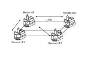
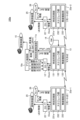
- FIG. 2 is a diagram showing an example of a use case of the communication system according to the first embodiment.
- FIG. 2 shows an example of a cooperative transport device that transports one piece of luggage 150 using multiple driving devices.
- each end station under four UEs is connected to a motor that constitutes the driving device, and controls the moving speed and direction.
- the speed and direction must be precisely matched among the four driving devices, and communication with lower latency is required.
- the wiring is replaced with a wireless line.
- the wireless line that replaces the wiring is realized by terminal-to-terminal communication.
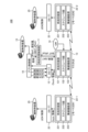
- FIG 3 is a diagram showing an example of the network configuration assumed in the first embodiment.
- the network assumed in this embodiment is composed of multiple UEs and direct communication paths between the UEs, which are the sections where terminal-to-terminal communication is performed.
- This network is called a local UE-to-UE wireless TSC network.
- one of the UEs becomes the master mobile station (Master UE) and transmits control information to the controlled devices (sometimes called controlled devices) 301-303, 311-313, 321-323 under its own station and other remote mobile stations (Remote UE), thereby realizing the desired operation in the entire TSC network.
- the link for terminal-to-terminal communication is called SideLink (SL).
- SL SideLink
- the double-headed arrow labeled "SL" indicates the link for terminal-to-terminal communication.
- FIG. 4 is a diagram showing an example of the configuration of a communication system 100 according to the first embodiment. Note that in FIG. 4, a mobile station is written as "UE.” This also applies to the drawings used in the following explanation.
- the communication system 100 includes one master mobile station 13 and multiple remote mobile stations 23 (remote mobile stations 23-1 and 23-2 are shown in FIG. 4).
- the network consisting of the master mobile station 13 and the multiple remote mobile stations 23 realizes time-synchronized communication.
- the master mobile station 13 and the remote mobile station 23 have terminal-to-terminal communication functions and can communicate directly with other mobile stations without going through a base station.
- the master mobile station 13 communicates directly with each of the remote mobile stations 23-1 and 23-2.
- the master mobile station 13 is connected to an application control unit 10 via a DS-TT (Device Side Tsn Translator) 12, which controls applications to be realized by a time synchronization network, which is a network formed by the master mobile station 13 and the remote mobile stations 23-1 and 23-2.
- DS-TT is specified in the above-mentioned document "3GPP TS23.501 V17.2.0 (2021-09)" and performs processing to realize the time synchronization function.
- a controlled device 15 that can be controlled without going through a wireless line is connected to the application control unit 10.
- the master mobile station 13 comprises a time synchronization unit 131 that controls the TSC function as a mobile station, a scheduler unit 132 that determines the radio resources to be used in terminal-to-terminal communication, and a radio function unit 133 that performs transmission and reception processing of radio signals.
- a grand master clock (GM) 14 that provides the reference clock of this time synchronization network is also connected to the master mobile station 13. Note that the reference clock does not necessarily have to be an independent functional block, and time information reproduced by a GPS receiver or time information generated by an oscillator built into the mobile station may be used.
- a time synchronization control unit 11 is provided between the master mobile station 13 and the application control unit 10, which controls the TSC function of the entire system including the master mobile station 13 and the multiple remote mobile stations 23.
- the remote mobile stations 23-1 and 23-2 have the same configuration as the master mobile station 13, but in FIG. 4, corresponding components are denoted with different reference numerals.
- the remote mobile stations 23-1 and 23-2 each include a time synchronization unit 231 having the same function as the time synchronization unit 131 of the master mobile station 13, a scheduler unit 232 having the same function as the scheduler unit 132 of the master mobile station 13, and a wireless function unit 233 having the same function as the wireless function unit 133 of the master mobile station 13.
- the remote mobile station 23 is connected to the controlled device 25 via a DS-TT 22 that performs the same processing as the DS-TT 12 described above.
- the wireless interface on SL is called PC5.
- the application control unit 10 and the time synchronization control unit 11 are provided, for example, in a control device that controls the operation of the controlled devices 15 and 25.
- FIG. 4 shows an example in which no controlled device is connected to the master mobile station 13
- a configuration in which a controlled device is connected to the master mobile station 13 may also be used, as in the example shown in FIG. 3.
- the application control unit 10 generates control information for operating a desired application.
- the cooperative transport device shown in FIG. 2 is taken up.
- the application control unit 10 generates control information such as speed, direction, and torque for the controlled device 15 under its control and the controlled device 25 under each of the multiple remote mobile stations 23.
- This control information can be expressed in various ways, and for example, it is possible to notify the angle information of each motor at a specific time, and the content of the control information is not limited.
- the purpose is to fix the delay time of the control information, which is the time required for the control information to arrive at the controlled devices 15 and 25 after the application control unit 10 outputs the control information.
- the application control unit 10 generates and outputs the control information taking into account the delay time of the control information.
- a specific communication session is set, wireless resources are allocated, and the control information is transmitted.
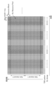
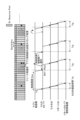
- Figure 5 shows an example of a frame format used by mobile stations when performing terminal-to-terminal communication in 5GS.
- a portion of the UL (UpLink) resources reserved for transmission from a mobile station to a base station in communication between the mobile station and the base station is allocated to the SL.
- the resources that can be allocated to the SL are an area designated by a time and frequency range called the SL Resource Pool. This area can be arranged quite discretely in terms of time.
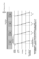
- FIG. 6 is a diagram showing an example of the control information transmission operation in the communication system 100 according to the first embodiment.
- FIG. 6 shows an example of transmitting control information from the application control unit 10 to a controlled device 25 under a remote mobile station 23 with a control period of 5 ms.
- the vertically long rectangles in the upper row indicate resources for wireless communication.
- "U” indicates a UL resource
- "D” indicates a DL (DownLink) resource.
- ⁇ indicates that the resource is allocated for terminal-to-terminal communication.
- the scheduler unit 132 of the master mobile station 13 continuously secures radio resources at 5 ms intervals as shown in FIG. 6. Specifically, the application control unit 10 issues an information transmission request at 5 ms intervals to the time synchronization control unit 11, and the time synchronization control unit 11 instructs the time synchronization unit 131 of the master mobile station 13 to secure resources at 5 ms intervals for terminal-to-terminal communication with the remote mobile station 23.
- the time synchronization unit 131 takes into consideration conflicts with communication resources used in other sessions and instructs the scheduler unit 132 to secure appropriate resources.
- the master DS-TT corresponds to the DS-TT 12 shown in FIG. 4
- the remote DS-TT corresponds to the DS-TT 22 shown in FIG. 4.
- the application control unit 10 In the case of the transmission operation of the control information shown in FIG. 6, the application control unit 10 generates the control information at time Ts and transmits the control information to the controlled device 25 via the master DS-TT (DS-TT12), the master UE (master mobile station 13), the remote UE (remote mobile station 23), and the remote DS-TT (DS-TT22).
- the time Ts is assumed to be a relative time from the head timing of the 5GS radio frame, or a relative time from any timing corresponding to the 5GS radio frame, but it may be an absolute time outside of 5GS such as Universal Time. If the transmission delay time in 5GS is Td 1 , the application control unit generates and transmits the control information of the controlled device 25 at time Ts+Td 1 at time Ts.
- the next information transmission timing is Ts+5 ms. Since the transmission delay time Td 1 in 5GS differs for each session, the application control unit 10 generates and transmits the control information at different timing for each session.
- the application control unit 10 When a plurality of controlled devices 25 exist under one remote mobile station 23, a plurality of sessions may be established between the master mobile station 13 and the remote mobile station 23. In this case, even if the controlled devices 25 are under the same remote mobile station 23, the control information is generated and transmitted at different timings for each controlled device 25.
- FIG. 7 is a diagram showing a first operation example of the communication system 100 according to the first embodiment.
- FIG. 7 shows a transmission operation of control information when resource reselection is performed in terminal-to-terminal communication.
- FIG. 7 shows an operation example when a slot of a different timing than before is reserved in resource reselection, specifically, an operation example when the position of the reserved radio resource is shifted 2 slots behind.
- the timing of the radio resource reserved for the control information transmission is delayed by 1 ms relative to the transmission timing of the application control.
- the delay time fluctuation is absorbed to some extent by the buffering of DS-TT22, but when the buffer amount is reduced to reduce the delay, the transmission delay time in 5GS is changed from Td 1 to Td 2 . This will lead to inconsistencies in the control information.
- a process for preventing such a problem from occurring is performed in the communication system 100 according to the present embodiment.
- the time synchronization unit 131 detects a change in the time position of the radio resource due to resource reselection, and notifies the time synchronization control unit 11 of the difference, i.e., the amount of change, for example, as a BAT (Burst Arrival Time) offset.
- the calculation of the transmission delay time Td 2 may be performed by the time synchronization unit 131. In this case, the new transmission delay time Td 2 is notified to the time synchronization control unit 11 from the time synchronization unit 131 together with the BAT offset.
- the application control unit 10 When the application control unit 10 receives information from the time synchronization control unit 11 that has calculated the new transmission delay time Td2 within 5GS, the application control unit 10 implements one of the following two types of countermeasures.
- the first countermeasure is to change the assumed transmission delay time in 5GS.
- this countermeasure is implemented. Specifically, when the time synchronization control unit 11 notifies the application control unit 10 of the BAT offset and the transmission delay time Td2 , the application control unit 10 changes the transmission delay time in communication with the controlled device 25 under the remote mobile station 23 to Td2 . That is, the application control unit 10 changes the transmission delay time to the controlled device 25 used when generating control information for the controlled device 25. After this, the application control unit 10 generates control information at the time Ts+ Td2 and continues to control the system.
- the second solution is to change Ts, which is the timing at which control information is transmitted from the application control unit 10 to the DS-TT 12. Naturally, it is desirable for the transmission delay time from the application control unit 10 to the controlled device 25 to be short. This second solution is explained using Figure 8.
- FIG. 8 is a diagram showing a second operation example of the communication system 100 according to the first embodiment. Like FIG. 7, FIG. 8 shows the operation of transmitting control information when resource reselection is performed in terminal-to-terminal communication. Like FIG. 7, FIG. 8 shows an example in which the position of the radio resource secured in resource reselection is shifted two slots back from the previous position.
- All of the functional units that make up the system including the application control unit 10 and the time synchronization control unit 11, receive clock information synchronized with the GM 14 and are time-synchronized. This does not necessarily mean that they are driven by the same clock, and time synchronization can be achieved by managing and correcting the frequency difference between the local clock and the GM clock.
- Clock information is distributed using PTP (Precision Time Protocol), ASTI (Access Stratum Timing Distribution System), etc.
- FIG. 9 is a flowchart showing an example of the operation of the communication system 100 according to the first embodiment.
- the flowchart in FIG. 9 shows the operation when resource reselection is performed in terminal-to-terminal communication.
- the scheduler unit 132 of the master mobile station 13 executes resource reselection (step S11).
- the time synchronization unit 131 checks whether or not the slot position has changed, that is, whether or not the time position of the radio resource has changed as a result of the execution of resource reselection (step S12). If the slot position has not changed (step S12: No), the operation ends. If the slot position has changed (step S12: Yes), the application control unit 10 adjusts the transmission timing of the control information (step S13). In this step S13, the transmission timing is adjusted using the method of changing the transmission delay time Td assumed in 5GS (the method shown in FIG. 7) or the method of changing the BAT (the method shown in FIG. 8) described above.
- the master mobile station 13 when the master mobile station 13 performs resource reselection for terminal-to-terminal communication, it checks whether the slot position has changed, and if there has been a change, it changes the transmission delay time expected within 5GS or the BAT. This makes it possible to realize synchronous control of multiple controlled devices even if the slot position has changed due to resource reselection for terminal-to-terminal communication in a network having a configuration including a section in which terminal-to-terminal communication is applied.
- the application control unit 10 and the time synchronization control unit 11 may be provided in a single device that controls multiple controlled devices using time-synchronized communication, or may be provided in different devices.
- the application control unit 10 may be provided in a cooperative operation control device, and the time synchronization control unit 11 may be provided in a time synchronization control device.
- the time synchronization unit 131 of the master mobile station 13 may be configured to have the functions of the time synchronization control unit 11, that is, the time synchronization unit 131 may also operate as the time synchronization control unit 11.
- the wireless function unit 133 of the master mobile station 13 and the wireless function units 233 of the remote mobile stations 23-1 and 23-2 are realized by, for example, a transceiver.
- the time synchronization unit 131 and scheduler unit 132 of the master mobile station 13 and the time synchronization unit 231 and scheduler unit 232 of the remote mobile stations 23-1 and 23-2 are realized by a processing circuit.
- the processing circuit may be a processor and memory that executes a program stored in a memory, or may be dedicated hardware.
- the processing circuit is also called a control circuit.
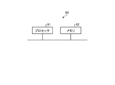
- FIG. 10 is a diagram showing an example of a processing circuit 90 in which a processing circuit for implementing a mobile station (master mobile station 13, remote mobile stations 23-1, 23-2) constituting the communication system 100 according to the first embodiment is implemented by a processor 91 and a memory 92.
- the processing circuit 90 shown in FIG. 10 includes a processor 91 and a memory 92.
- Each function of the processing circuit 90 is implemented by software, firmware, or a combination of software and firmware.
- the software or firmware is written as a program and stored in the memory 92.
- each function is implemented by the processor 91 reading and executing the program stored in the memory 92.
- the processing circuit 90 includes a memory 92 for storing a program that will result in the processing of the mobile station constituting the communication system 100.
- This program can also be said to be a program for causing the mobile station to execute each function implemented by the processing circuit 90.
- This program may be provided by a storage medium in which the program is stored, or by other means such as a communication medium.
- the processor 91 is, for example, a CPU (Central Processing Unit), a processing unit, an arithmetic unit, a microprocessor, a microcomputer, or a DSP (Digital Signal Processor).
- the memory 92 is, for example, a non-volatile or volatile semiconductor memory such as a RAM (Random Access Memory), a ROM (Read Only Memory), a flash memory, an EPROM (Erasable Programmable ROM), or an EEPROM (registered trademark) (Electrically EPROM).
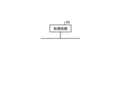
- FIG. 11 is a diagram showing an example of a processing circuit 93 in the case where the processing circuit that realizes the mobile station constituting the communication system 100 according to the first embodiment is configured with dedicated hardware.
- the processing circuit 93 shown in FIG. 11 corresponds to, for example, a single circuit, a composite circuit, a programmed processor, a parallel programmed processor, an ASIC (Application Specific Integrated Circuit), an FPGA (Field Programmable Gate Array), or a combination of these.
- the processing circuit may be partially realized with dedicated hardware and partially realized with software or firmware. In this way, the processing circuit can realize each of the above-mentioned functions by dedicated hardware, software, firmware, or a combination of these.
- Embodiment 2 In a control application such as that shown in Fig. 2, it is generally necessary not only to send control information one-way, but also to obtain the state of the controlled device by a sensor and feed it back to the control device. Therefore, in this embodiment, a communication system that realizes feedback from the controlled device is disclosed.
- FIG. 12 is a diagram showing an example of the configuration of a communication system 100a according to the second embodiment.
- components common to the communication system 100 according to the first embodiment shown in FIG. 4 are given the same reference numerals as in the communication system 100. Explanations of components given the same reference numerals as in the communication system 100 are omitted.
- the communication system 100a includes a master mobile station 13 and multiple remote mobile stations 23a (remote mobile stations 23a-1 and 23a-2 are shown in FIG. 12).
- the remote mobile station 23a includes a time synchronization unit 231a, a scheduler unit 232, and a wireless function unit 233.
- the communication system 100a also includes an application control unit 10a and a time synchronization control unit 11a.
- Each controlled device 25 is equipped with a sensor 26.
- the sensor information output by the sensor 26 is transmitted to the application control unit 10a via the DS-TT 22, the remote mobile station 23a, the master mobile station 13, and the DS-TT 12.
- the operation of transmitting control information from the master mobile station 13 to the remote mobile station 23a in the communication system 100a is the same as that in the communication system 100 according to the first embodiment, and therefore will not be described.
- the sensor 26 is responsible for measuring the state of the controlled device 25 and notifying the application control unit 10a. If the sensor 26 is a high-performance sensor, it creates sensor information by adding a timestamp of the measurement time to the measurement information and transmits this sensor information. In this case, the application control unit 10a can adjust the processing timing, etc. based on the timestamp included in the sensor information. On the other hand, in conventional sensors, all information transmission paths are connected by wire, and many of them are processed under the assumption of a fixed delay time. In addition, due to the transmission format, there are also cases where a new timestamp cannot be added.
- a communication system 100a that does not require a timestamp that is, a communication system 100a that makes it possible to use information transmitted from the sensor 26 to the application control unit 10a without using a timestamp for synchronous control of the controlled device 25, will be described.
- FIG. 13 is a diagram showing an example of a sensor information transmission operation in the communication system 100a according to the second embodiment.
- FIG. 13 shows an example of the timing when information is transmitted from the sensor 26 to the application control unit 10a. It is assumed that the sensor 26 generates information every 5 ms.
- sensor information occurs at a relative time Ts from some reference timing of the radio frame, and the information is transmitted to the application control unit 10a via the DS-TT 22, the remote mobile station 23a, the master mobile station 13, and the DS-TT 12.
- the arrival time of the sensor information at the application control unit 10a is the time obtained by adding the assumed transmission delay time in 5GS to the relative time Ts of the sensor information.
- the application control unit 10a can recognize that the received sensor information is from the time Ts based on the information on the transmission delay time Td 4 provided by the time synchronization control unit 11a.
- the time synchronization unit 231a detects the shift in the slot position, and the difference is notified to the time synchronization control unit 11a as, for example, a BAT offset.
- the calculation of the transmission delay time Td5 may be performed by the time synchronization unit 231a. In this case, the new transmission delay time Td5 is notified to the time synchronization control unit 11a together with the BAT offset.
- the application control unit 10a In general, it is desirable for the sensor information obtained by the application control unit 10a to be as new as possible. In other words, it is desirable to change the generation timing of the sensor information and minimize the BAT offset. For this reason, the application control unit 10a or the time synchronization control unit 11a notifies the sensor 26 of a new transmission timing (BAT) of the sensor information that can minimize the BAT offset.
- the sensor 26 calculates and updates the transmission timing Ts from the sensor 26 based on the BAT.
- the time synchronization control unit 11a calculates the 5GS delay time from DS-TT22 to DS-TT12 due to the new transmission timing Ts and notifies the application control unit 10a. Upon receiving this notification, the application control unit 10a changes the 5GS delay time used in the generation process of control information for the controlled device 25 to the 5GS delay time notified by the time synchronization control unit 11.
- the application control unit 10a acquires the transmission delay time expected within 5GS from the time synchronization control unit 11a, and calculates the time when the sensor information acquired from the sensor 26 connected to the remote mobile station 23a was transmitted based on the acquired transmission delay time.
- the remote mobile station 23a performs resource reselection for terminal-to-terminal communication, it checks whether or not there has been a change in the slot position, and if there has been a change, the time synchronization control unit 11a changes the transmission delay time expected within 5GS, and the application control unit 10a uses the changed transmission delay time to calculate the time when the sensor information was transmitted.
- the time synchronization control unit 11a determines a new transmission timing for the sensor information and notifies the sensor 26 of the new transmission timing.
- the sensor 26 changes the transmission timing of the sensor information to the notified transmission timing.
- the application control unit 10a can grasp the time when sensor information was transmitted from the remote mobile station 23a to the application control unit 10a, thereby realizing synchronous control of multiple controlled devices.
Landscapes
- Engineering & Computer Science (AREA)
- Computer Networks & Wireless Communication (AREA)
- Signal Processing (AREA)
- Mobile Radio Communication Systems (AREA)
Abstract
移動局(13)は、端末間通信が可能な複数の移動局を含み、時刻同期型通信を実現するネットワークにおいて、被制御装置との間の情報伝送路における伝送遅延時間を考慮して被制御装置を制御する連携動作制御装置で生成された制御情報を端末間通信により送信するマスタ移動局として動作し、制御情報の送信先の被制御装置が接続される移動局であるリモート移動局との端末間通信で使用する無線リソースの決定および変更を行うスケジューラ部(132)と、スケジューラ部が無線リソースを変更したときに無線リソースの時間的位置が変更されたか否かを確認し、時間的位置が変更された場合には時間的位置の変更量を、伝送遅延時間を算出する時刻同期制御部(11)に通知する時刻同期部(131)と、を備える。
Description
本開示は、時刻同期型通信を行う通信システムを構成する移動局、時刻同期制御装置、連携動作制御装置、通信システム、同期制御方法、制御回路および記憶媒体に関する。
近年、複数の産業機器をネットワークで接続し、連携動作させるシステムが開発されている。このようなシステムで使用されるアプリケーションは多岐に渡る。例えば、工場の生産ラインにおいて、複数のロボットアームが、ネットワークで接続され、特定の制御装置からの指令に基づいて時刻同期して連携したモノづくりを行うシステムが実用化されている。このようなネットワークも多くの選択肢があり、フィールドバス、産業用イーサネット(登録商標)といった名称で複数の規格が提供されている。複数の機器がネットワークで連携されることによって、緊急時の対応、センサ情報の共有なども可能となり、安全で効率的なシステムの構築が可能となっている。フィールドバス、産業用イーサネットなどについては、機器間で厳密な時刻同期が必要となるため、信号伝送における遅延を極力短くするような設計がなされるとともに、時刻同期を行うTSN(Time Sensitive Networking)と呼ばれる規格が広く用いられている。
一方で、少量多品種生産への対応、また、生産ラインのみならず無人搬送車であるAGV(Automatic Guided Vehicle)などの移動体もネットワークに組み込むための対応として、無線通信技術を活用した時刻同期型通信、いわゆるTSC(Time Sensitive Communication)の開発が始まっている。1つの例として、移動体通信システムの標準化を行っている3GPP(登録商標)(Third Generation Partnership Project)で検討が進められている5GS(Fifth Generation System)が挙げられる。
例えば、特許文献1には、コア装置、無線アクセス装置である基地局、端末装置である移動局、TSNトランスレータなどから構成されるTSC用ネットワークの技術が開示されている。特許文献1の図2では、コア装置の外側のTSN working domain上にあるネットワーク構成機器であるEnd Stationと、端末装置に接続されたEnd Stationとが5GSを介して接続され、両機器間で時刻同期型通信を行う構成が示されている。
同期動作するEnd Station間を5GSおよび他の有線ネットワークなどで接続する場合、時刻同期サービスを提供する5GSは、End Stationから見ると仮想的なTSNブリッジとして動作している。5GSが担う仮想的なTSNブリッジは、TSNトランスレータなどがデータ信号を滞留可能なバッファを備えることで、遅延時間が一定となるよう期待される。
一般論として、5GSに属する基地局内のスケジューラ機能部は、仮想的なTSNを構成するノード間の伝搬遅延ができるだけ一定になるように、情報伝送に必要な無線リソースを割り当てる。
移動体通信システムの機能の1つとして、基地局を介さずに端末装置同士が直接通信を行う機能(以下では、端末間通信と称する場合がある)が3GPPで規格化されており、この機能を上記の同期動作に適用することが考えられる。すなわち、同期動作する複数のEnd Stationに対して同期動作実現のための情報を伝送する経路に、端末装置同士が直接通信する区間が含まれるケースが考えられる。しかしながら、端末間通信で使用する無線リソースの割り当ては、通常、端末装置間で行われ、基地局内のスケジューラ機能部が関与することはしない。このため、仮想的なTSNを構成するノード間の伝搬遅延ができるだけ一定になるような制御を基地局内のスケジューラ機能部が行うことは難しい。
本開示は、上記に鑑みてなされたものであって、端末装置同士が直接通信を行う区間が含まれるネットワークを介して接続される複数の機器の同期制御を実現することが可能な移動局を得ることを目的とする。
上述した課題を解決し、目的を達成するために、本開示は、端末間通信が可能な複数の移動局を含み、時刻同期型通信を実現するネットワークにおいて、被制御装置との間の情報伝送路における伝送遅延時間を考慮して被制御装置を制御する連携動作制御装置で生成された制御情報を端末間通信により送信するマスタ移動局として動作する移動局であって、制御情報の送信先の被制御装置が接続される移動局であるリモート移動局との端末間通信で使用する無線リソースの決定および変更を行うスケジューラ部と、スケジューラ部が無線リソースを変更したときに無線リソースの時間的位置が変更されたか否かを確認し、時間的位置が変更された場合には時間的位置の変更量を、伝送遅延時間を算出する時刻同期制御部に通知する時刻同期部と、を備えることを特徴とする。
本開示にかかる移動局は、端末装置同士が直接通信を行う区間が含まれるネットワークを介して接続される複数の機器の同期制御を実現できる、という効果を奏する。
以下に、本開示の実施の形態にかかる移動局、時刻同期制御装置、連携動作制御装置、通信システム、同期制御方法、制御回路および記憶媒体を図面に基づいて詳細に説明する。
実施の形態1.
まず、比較例として、端末装置同士が直接通信を行う区間を含まないネットワークを介して同期制御を実現する方法について説明する。
まず、比較例として、端末装置同士が直接通信を行う区間を含まないネットワークを介して同期制御を実現する方法について説明する。
上述したように、時刻同期サービスを提供する5GSにおいて、基地局内のスケジューラ機能部は、ノード間の伝搬遅延ができるだけ一定になるように無線リソースを割り当てる。しかしながら、End Stationが属するTSN working domain上のグランドマスタークロックと5GSが独自に有するクロック源との周波数オフセット、5GSがサービスを同時に提供している他ユーザのトラフィック状況などの影響で、End Stationからの情報パケットの到着タイミングと、無線リソースの割り当てタイミングが合わなくなるなど、伝搬遅延が合わなくなる問題がある。この問題を解決するために、タイミング誤差を調整するしくみも導入されており、例えば、3GPP TS23.501 V17.2.0(2021-09)のTable5.27.2-1では、TSCのパケットを制御するための情報として、図1に示すTSCAI(Time Sensitive Communication Assistance Information)が規定されている。時刻同期サービスを実現する比較例のシステムでは、End Stationが送信する情報パケットの周期および5GSへの到着タイミングをTSCAIで指定することにより、伝送遅延時間の短縮化を実現している。TSCAIの一部の情報は、コア機能の一部であるAMF(Access and Mobility Management Function)から(R)ANおよびUE(User Equipment)に渡され、無線伝送のスケジューリングに用いられる。TSCAIを(R)ANのスケジューリングに利用する例は、前述の特許文献1の段落0058にも開示されている。なお、UEは、端末装置または移動局とも称される。
TSCAIを利用した前述の遅延時間の短縮化手法は5GSのコア機能部の存在が前提となるため、端末装置同士が直接通信を行う区間が含まれるシステムに対して適用することはできない。よって、5GSのコア機能部を必要としない手法の実現が望まれる。
つづいて、本実施の形態にかかる通信システムについて説明する。図2は、実施の形態1にかかる通信システムのユースケースの一例を示す図である。図2では、1つの荷物150を複数の駆動装置で運搬する協調型運搬装置の例を示している。このユースケースでは、4台のUE配下にある各End Stationが、駆動装置を構成するモーターに接続され、移動速度や方向を制御している。この場合、荷物150をうまく運ぶためには、速度や方向を4台の駆動装置で厳密に一致させる必要があり、より低遅延の通信が求められる。言い換えれば、従来は有線で直結され、固定遅延時間で制御されるサーボ制御のようなアプリケーションにおいて、配線を無線回線に置き換えることとなる。本実施の形態では、配線と置き換える無線回線を端末間通信で実現する。
図3は、実施の形態1で想定するネットワークの構成例を示す図である。本実施の形態で想定するネットワークは、複数のUEと、端末間通信が行われる区間であるUE間の直接通信経路とで構成される。このネットワークを局所的なUE間無線TSC網と称する。例えば、上記の図2に示したユースケースでは、UEのうち一つがマスタ移動局(Master UE)となり、自局、および他のリモート移動局(Remote UE)配下にある制御対象機器(被制御装置と称する場合もある)301~303,311~313,321~323に対して制御情報を送信し、TSC網全体で所望の動作を実現する。なお、3GPPにおいて端末間通信のリンクはSideLink(SL)と呼ばれる。図3では、「SL」と記載した両方向矢印が端末間通信のリンクを示す。
図4は、実施の形態1にかかる通信システム100の構成例を示す図である。なお、図4では、移動局を「UE」と記載している。これ以降の説明で用いる図面も同様である。
本実施の形態にかかる通信システム100は、1台のマスタ移動局13と、複数台のリモート移動局23(図4においてはリモート移動局23-1,23-2を図示)とを含む。マスタ移動局13および複数のリモート移動局23で構成されるネットワークは、時刻同期型通信を実現する。マスタ移動局13およびリモート移動局23は、端末間通信機能を有し、基地局を介さずに他の移動局と直接通信することが可能である。通信システム100では、マスタ移動局13が、リモート移動局23-1および23-2のそれぞれと直接通信を行う。
マスタ移動局13には、マスタ移動局13とリモート移動局23-1および23-2とで形成されるネットワークである時刻同期ネットワークによって実現すべきアプリケーションを統括するアプリ制御部10がDS-TT(Device Side Tsn Translator)12を介して接続される。DS-TTは上記文献「3GPP TS23.501 V17.2.0(2021-09)」で規定されており、時刻同期機能実現のための処理を行う。また、アプリ制御部10には、無線回線を介さずに制御可能な被制御装置15が接続される。
マスタ移動局13は、移動局としてのTSC機能を制御する時刻同期部131と、端末間通信で使用する無線リソースを決定するスケジューラ部132と、無線信号の送受信処理を行う無線機能部133とを備える。また、この時刻同期ネットワークの基準クロックを提供するグランドマスタークロック(GM)14がマスタ移動局13に接続されている。なお、基準クロックは必ずしも独立した機能ブロックである必要は無く、GPS受信機で再生される時刻情報や、移動局が内蔵する発振器から生成される時刻情報を用いてもよい。
また、マスタ移動局13とアプリ制御部10との間に、マスタ移動局13および複数のリモート移動局23を含むシステム全体のTSC機能を制御する時刻同期制御部11が設けられている。
リモート移動局23-1および23-2もマスタ移動局13と同一の構成であるが、図4では対応する構成要素に異なる符号を付している。リモート移動局23-1および23-2は、マスタ移動局13の時刻同期部131と同様の機能を有する時刻同期部231と、マスタ移動局13のスケジューラ部132と同様の機能を有するスケジューラ部232と、マスタ移動局13の無線機能部133と同様の機能を有する無線機能部233と、を備える。リモート移動局23は、上記のDS-TT12と同様の処理を行うDS-TT22を介して、被制御装置25と接続される。なお、3GPPにおいてSL上の無線インタフェースはPC5と呼称される。
アプリ制御部10および時刻同期制御部11は、例えば、被制御装置15および25の動作を制御する制御装置に設けられる。
なお、図4では、マスタ移動局13に被制御装置が接続されていない例を示したが、図3に示す例と同様に、マスタ移動局13に被制御装置が接続された構成としてもよい。
つづいて、実施の形態1にかかる通信システム100の動作について説明する。アプリ制御部10は、所望のアプリケーションを動作させるための制御情報を生成する。例として、図2に示した協調型運搬装置を取り上げる。この例では、アプリ制御部10は、配下にある被制御装置15および複数のリモート移動局23それぞれの配下にある被制御装置25に対して、速度、方向、トルクといった制御情報を生成する。この制御情報は多様な表現が可能であり、例えば特定時刻の個々のモーターの角度情報を通知するといったことも可能であり、制御情報の中身を限定するものではない。本実施の形態においては、アプリ制御部10が制御情報を出力してからこの制御情報が被制御装置15および25に到着するまでに要する時間である、制御情報の遅延時間を固定することが目的である。このため、アプリ制御部10は、制御情報の遅延時間を考慮し、制御情報を生成して出力する。この制御情報をアプリ制御部10から、リモート移動局23配下の被制御装置25に伝送するために、特定の通信セッションが設定され、無線リソースが割り当てられて、制御情報が伝送される。
図5は、5GSで移動局が端末間通信を行う際に用いるフレームフォーマットの一例を示す図である。SLには、移動局と基地局との通信において移動局から基地局への送信用として確保されているUL(UpLink)リソースの一部が割り当てられる。SLに割り当て可能なリソースは、SL Resource Poolと呼ばれる時間および周波数範囲で指定される領域である。この領域は、時間的に見て相当に離散的に配置される可能性がある。
図6は、実施の形態1にかかる通信システム100における制御情報の伝送動作の一例を示す図である。図6は、制御周期5msでアプリ制御部10からリモート移動局23配下の被制御装置25へ制御情報を伝送する例を示す。上段の縦長の長方形は無線通信用のリソースを示す。「U」はULリソースを示し、「D」はDL(DownLink)リソースを示す。また、「●」は端末間通信に割り当てられたリソースであることを示す。
図6に示したような周期的制御を行うアプリケーション向けには、セミパーシステントスケジューリング(Semi-Persistent Scheduling)と呼ばれるリソース割り当てが行われる。マスタ移動局13のスケジューラ部132は、図6に示すように5ms周期で継続的に無線リソースを確保する。具体的には、アプリ制御部10から時刻同期制御部11に対し、5ms周期での情報伝送要求が出され、時刻同期制御部11はマスタ移動局13の時刻同期部131に対して、リモート移動局23との端末間通信向けに、5ms周期でのリソース確保が指示される。時刻同期部131は他セッションで使用する通信リソースとの競合なども考慮し、スケジューラ部132に適切なリソース確保を指示する。図6において、マスタDS-TTは図4に示したDS-TT12に対応し、リモートDS-TTは図4に示したDS-TT22に対応する。
図6に示す例の制御情報の伝送動作の場合、アプリ制御部10は、時刻Tsに制御情報を生成し、マスタDS-TT(DS-TT12)、マスタUE(マスタ移動局13)、リリモートUE(リモート移動局23)およびリモートDS-TT(DS-TT22)を介して、被制御装置25へ制御情報を伝送する。なお、時刻Tsは5GS無線フレームの先頭タイミングからの相対時刻、ないしは5GS無線フレームに対応するいずれかのタイミングからの相対時刻を想定するが、世界標準時のような5GS外の絶対時刻であっても構わない。5GS内の伝送遅延時間をTd1とすれば、アプリ制御部は時刻Tsにおいて、時刻Ts+Td1時点の被制御装置25の制御情報を生成して伝送する。図6に示す例では、次の情報伝送タイミングはTs+5msになる。5GS内の伝送遅延時間Td1はセッション毎に異なるため、アプリ制御部10はセッション毎に異なるタイミングで制御情報を生成して伝送する。1台のリモート移動局23の配下に被制御装置25が複数存在する場合、マスタ移動局13とこのリモート移動局23との間で複数のセッションが張られる可能性もある。その際は同じリモート移動局23配下ではあっても、被制御装置25毎に異なるタイミングで制御情報の生成および伝送が行われる。
ここで、5GSの規格によれば、特定のセッションのための端末間通信向けにSLリソースを確保する位置は周期的に変更することが義務付けられている。これは「リソース再選択」と呼ばれる動作である。リソース再選択の際、同一タイミングのSlotで、異なる周波数位置に無線リソースが確保できる場合は問題ないが、異なるSlotに無線リソースが確保される場合もある。図7は、実施の形態1にかかる通信システム100の第1の動作例を示す図である。図7は、端末間通信においてリソース再選択を行う場合の制御情報の伝送動作を示す。図7は、リソース再選択においてそれまでとは異なるタイミングのSlotが確保される場合の動作例、具体的には、確保される無線リソースの位置が2Slot後ろにずれた場合の動作例を示している。この例の場合、制御情報伝送のために確保される無線リソースのタイミングがアプリ制御の送信タイミングに対して相対的に1ms遅れることとなる。DS-TT22のバッファリングである程度遅延時間の変動が吸収されるが、低遅延化のためにバッファ量を小さくしている場合、5GS内の伝送遅延時間がTd1からTd2に変更される。これは制御情報の齟齬を招くこととなる。
このような問題の発生を防止するための処理が本実施の形態にかかる通信システム100で行われる。具体的には、通信システム100では、リソース再選択による無線リソースの時間的位置の変更を時刻同期部131が検知し、その差異すなわち変更量を、例えばBAT(Burst Arrival Time) offsetとして時刻同期制御部11に通知する。時刻同期制御部11は時刻同期部131から通知されたBAT offsetであるオフセット情報に基づいて新たな5GS内の伝送遅延時間Td2を計算し、アプリ制御部10に対して、現在のBAT(=Ts)、5GS内の伝送遅延時間およびBAT offsetの全部、もしくは一部の情報を通知する。なお、伝送遅延時間Td2の計算は時刻同期部131が行ってもよい。この場合、BAT offsetと共に新たな伝送遅延時間Td2が時刻同期部131から時刻同期制御部11に通知される。
アプリ制御部10は、新たな5GS内の伝送遅延時間Td2を計算した時刻同期制御部11から情報の通知を受けると、以下に示す2種類の対処方法のいずれかを実施する。
1つ目の対処方法は、想定する5GS内の伝送遅延時間の変更である。図7に示す例ではこの対処方法を実施している。具体的には、時刻同期制御部11からBAT offsetや伝送遅延時間Td2が通知されると、アプリ制御部10はリモート移動局23配下の被制御装置25との通信における伝送遅延時間をTd2に変更する。すなわち、アプリ制御部10は、被制御装置25に対する制御情報を生成する際に使用する被制御装置25までの伝送遅延時間を変更する。これ以降、アプリ制御部10は、時刻Ts+Td2の制御情報を生成し、システムの制御を継続する。
2つ目の対処方法は、アプリ制御部10からDS-TT12に制御情報が送信されるタイミングであるTsを変更することである。当然ながら、アプリ制御部10から被制御装置25までの伝送遅延時間は短い方が望ましい。この2つ目の対処方法について、図8を用いて説明する。
図8は、実施の形態1にかかる通信システム100の第2の動作例を示す図である。図8は、図7と同様に、端末間通信においてリソース再選択を行う場合の制御情報の伝送動作を示す。図8は、図7と同様に、リソース再選択において確保される無線リソースの位置がそれまでよりも2Slot後ろにずれた場合の例を示している。
リソース再選択により無線回線での送信タイミングが1ms遅れると、アプリ制御部10は、BAT(=Ts)を1ms遅らせて伝送遅延時間の最小化を図る。新たな5GS内の伝送遅延時間をTd3とすれば、アプリ制御部10はTs+Td3時点での制御情報を生成し、送信する。一般的にTd1とTd3は近い時間長になると考えられるが、必ずしも同一になるとは限らない。
なお、アプリ制御部10および時刻同期制御部11を含め、システムを構成する各機能部は全てGM14に同期したクロック情報を受け取り、時刻同期されている。これは、必ずしも同一クロックで駆動されていることに限るものでは無く、ローカルクロックとGMクロックの周波数差を管理して、補正をかけることで時刻同期を実現する構成でも構わない。クロック情報はPTP(Precision Time Protocol)、ASTI(Access Stratum Timing Distribution System)などを用いて配信される。
図9は、実施の形態1にかかる通信システム100の動作の一例を示すフローチャートである。図9のフローチャートは、端末間通信においてリソース再選択を実行した場合の動作を示す。
通信システム100において、まず、マスタ移動局13のスケジューラ部132がリソース再選択を実行する(ステップS11)。次に、時刻同期部131がスロット位置の変更があったか否か、すなわち、リソース再選択の実行に伴い無線リソースの時間的位置が変更されたか否かを確認する(ステップS12)。スロット位置の変更がない場合(ステップS12:No)、動作を終了する。スロット位置の変更がある場合(ステップS12:Yes)、アプリ制御部10が制御情報の送信タイミングを調整する(ステップS13)。このステップS13では、上述した、5GS内で想定する伝送遅延時間Tdを変更する方法(図7に示す方法)またはBATを変更する方法(図8に示す方法)を使用して送信タイミングを調整する。
このように、本実施の形態にかかる通信システム100において、マスタ移動局13は、端末間通信のリソース再選択を実施した場合、スロット位置の変更があったか否かを確認し、変更があった場合には、5GS内で想定される伝送遅延時間の変更またはBATの変更を実施する。これにより、端末間通信が適用される区間が含まれる構成のネットワークにおいて端末間通信のリソース再選択でスロット位置が変化した場合でも、複数の被制御装置の同期制御を実現できる。
なお、アプリ制御部10および時刻同期制御部11は、時刻同期型通信を用いて複数の被制御装置の制御を行う1つの装置に設けられてもよいし、異なる装置に設けられてもよい。例えば、アプリ制御部10が連携動作制御装置に設けられ、時刻同期制御部11が時刻同期制御装置に設けられてもよい。また、マスタ移動局13の時刻同期部131が時刻同期制御部11の機能を有する構成、すなわち、時刻同期部131が時刻同期制御部11としての動作も行う構成としてもよい。
つづいて、通信システム100の各装置のハードウェア構成について説明する。マスタ移動局13の無線機能部133、リモート移動局23-1および23-2の無線機能部233は、例えばトランシーバで実現される。マスタ移動局13の時刻同期部131およびスケジューラ部132と、リモート移動局23-1および23-2の時刻同期部231およびスケジューラ部232とは、処理回路により実現される。処理回路は、メモリに格納されるプログラムを実行するプロセッサおよびメモリであってもよいし、専用のハードウェアであってもよい。処理回路は制御回路とも呼ばれる。
図10は、実施の形態1にかかる通信システム100を構成する移動局(マスタ移動局13、リモート移動局23-1,23-2)を実現する処理回路をプロセッサ91およびメモリ92で実現する場合の処理回路90の例を示す図である。図10に示す処理回路90は、プロセッサ91およびメモリ92を備える。処理回路90の各機能は、ソフトウェア、ファームウェア、またはソフトウェアとファームウェアとの組み合わせにより実現される。ソフトウェアまたはファームウェアはプログラムとして記述され、メモリ92に格納される。処理回路90では、メモリ92に記憶されたプログラムをプロセッサ91が読み出して実行することにより、各機能を実現する。すなわち、処理回路90は、通信システム100を構成する移動局の処理が結果的に実行されることになるプログラムを格納するためのメモリ92を備える。このプログラムは、処理回路90により実現される各機能を移動局に実行させるためのプログラムであるともいえる。このプログラムは、プログラムが記憶された記憶媒体により提供されてもよいし、通信媒体など他の手段により提供されてもよい。
プロセッサ91は、例えば、CPU(Central Processing Unit)、処理装置、演算装置、マイクロプロセッサ、マイクロコンピュータ、またはDSP(Digital Signal Processor)などである。また、メモリ92は、例えば、RAM(Random Access Memory)、ROM(Read Only Memory)、フラッシュメモリ、EPROM(Erasable Programmable ROM)、EEPROM(登録商標)(Electrically EPROM)などの、不揮発性または揮発性の半導体メモリである。
図11は、実施の形態1にかかる通信システム100を構成する移動局を実現する処理回路を専用のハードウェアで構成する場合の処理回路93の例を示す図である。図11に示す処理回路93は、例えば、単一回路、複合回路、プログラム化したプロセッサ、並列プログラム化したプロセッサ、ASIC(Application Specific Integrated Circuit)、FPGA(Field Programmable Gate Array)、またはこれらを組み合わせたものが該当する。処理回路については、一部を専用のハードウェアで実現し、一部をソフトウェアまたはファームウェアで実現するようにしてもよい。このように、処理回路は、専用のハードウェア、ソフトウェア、ファームウェア、またはこれらの組み合わせによって、上述の各機能を実現することができる。
実施の形態2.
図2に示すような制御系アプリケーションでは、一般的に制御情報を一方的に送るだけでなく、被制御装置の状態をセンサで取得し、制御装置にフィードバックさせる必要がある。そこで、本実施の形態では、被制御装置からのフィードバックを実現する通信システムを開示する。
図2に示すような制御系アプリケーションでは、一般的に制御情報を一方的に送るだけでなく、被制御装置の状態をセンサで取得し、制御装置にフィードバックさせる必要がある。そこで、本実施の形態では、被制御装置からのフィードバックを実現する通信システムを開示する。
図12は、実施の形態2にかかる通信システム100aの構成例を示す図である。図12では、図4に示した実施の形態1にかかる通信システム100と共通の構成要素に通信システム100と同じ符号を付している。通信システム100と同じ符号が付された構成要素については説明を省略する。
通信システム100aは、マスタ移動局13と、複数のリモート移動局23a(図12においてはリモート移動局23a-1,23a-2を図示)とを含む。リモート移動局23aは、時刻同期部231a、スケジューラ部232および無線機能部233を備える。また、通信システム100aは、アプリ制御部10aおよび時刻同期制御部11aを含む。
被制御装置25のそれぞれにはセンサ26が取り付けられている。センサ26が出力するセンサ情報は、DS-TT22,リモート移動局23a、マスタ移動局13およびDS-TT12を介してアプリ制御部10aに伝送される。
つづいて、実施の形態2にかかる通信システム100aの動作について説明する。通信システム100aにおいてマスタ移動局13からリモート移動局23aへ制御情報を伝送する動作は実施の形態1にかかる通信システム100と同様であるため、説明を省略する。
センサ26は被制御装置25の状態を測定してアプリ制御部10aへ通知する役割を担う。ここで、センサ26が高機能なセンサであれば、測定時刻のタイムスタンプを測定情報に付加してセンサ情報を作成し、このセンサ情報を伝送する。この場合、センサ情報に含まれるタイムスタンプに基づきアプリ制御部10aが処理タイミングなどの調整を行うことが可能となる。一方、従来のセンサは情報の伝送経路が全て有線で接続され、固定遅延時間を前提に処理されるものも多い。また、伝送フォーマットの関係から、新たにタイムスタンプを付加できないケースも想定される。このため、本実施の形態では、タイムスタンプを不要とする通信システム100a、すなわち、タイムスタンプを利用することなくセンサ26からアプリ制御部10aへ伝送される情報を被制御装置25の同期制御に用いることができるようにする通信システム100aについて説明する。
図13は、実施の形態2にかかる通信システム100aにおけるセンサ情報の伝送動作の一例を示す図である。図13は、センサ26からアプリ制御部10aへ情報伝送を行う場合のタイミングの一例を示す。センサ26では5ms毎に情報が発生するものとしている。
図13に示す例では、無線フレームの何らかの基準タイミングから相対時刻Tsでセンサ情報が発生し、DS-TT22、リモート移動局23a、マスタ移動局13、DS-TT12を経て、アプリ制御部10aに情報が伝送される。アプリ制御部10aへのセンサ情報の到着時刻は、センサ情報の上記相対時刻Tsに5GS内の想定する伝送遅延時間が加算された時刻となる。このとき、5GS内の伝送遅延時間がTd4であるとすれば、アプリ制御部10aは時刻同期制御部11aから提供される伝送遅延時間Td4の情報により、受信したセンサ情報がTs時点のものであると認識できる。リソース再選択においてリモート移動局23aが確保する無線リソースが2Slot(=1ms)後ろにずれた場合、時刻同期部231aでSlot位置のずれが検知され、その差異が例えばBAT offsetとして時刻同期制御部11aに通知される。時刻同期制御部11aは、この情報から新たな5GS内の伝送遅延時間Td5を計算し、アプリ制御部10aに対して現在のBAT(=Ts)、5GS内の伝送遅延時間およびBAT offsetの全部、もしくは一部の情報を通知する。なお、伝送遅延時間Td5の計算は時刻同期部231aが行ってもよい。この場合、BAT offsetと共に新たな伝送遅延時間Td5が時刻同期制御部11aに通知される。
アプリ制御部10aは時刻同期制御部11aから伝送遅延時間Td5を受け取り、センサ情報が生成された時刻Tsを計算する。すなわち、DS-TT12からアプリ制御部10aへ時刻Trにセンサ情報が渡されたとすると、アプリ制御部10aはセンサ情報の生成時刻をTs=Tr-Td5で推定できる。なお、時刻同期制御部11aから直接Tsをアプリ制御部10aに渡しても構わない。
一般的に、アプリ制御部10aが得るセンサ情報も、できる限り新しい情報であることが望まれる。すなわち、センサ情報の生成タイミングを変更し、BAT offsetを最小化することが望まれる。このため、アプリ制御部10aもしくは時刻同期制御部11aは、センサ26に対し、BAT offsetを最小化できる、センサ情報の新たな送信タイミング(BAT)を通知する。センサ26では、BATを基準にセンサ26からの送信タイミングTsが算出、更新される。新たな送信タイミングTsによるDS-TT22からDS-TT12までの5GS内遅延時間が時刻同期制御部11aで計算され、アプリ制御部10aに通知される。この通知を受けたアプリ制御部10aは、被制御装置25に対する制御情報の生成処理で使用する5GS内遅延時間を、時刻同期制御部11から通知された5GS内遅延時間に変更する。
以上説明したように、本実施の形態にかかる通信システム100aにおいて、アプリ制御部10aは、5GS内で想定される伝送遅延時間を時刻同期制御部11aから取得し、取得した伝送遅延時間に基づいて、リモート移動局23aに接続されたセンサ26から取得したセンサ情報が送信された時刻を算出する。リモート移動局23aは、端末間通信のリソース再選択を実施した場合、スロット位置の変更があったか否かを確認し、変更があった場合、時刻同期制御部11aが、5GS内で想定される伝送遅延時間を変更し、アプリ制御部10aは、変更後の伝送遅延時間を使用して、センサ情報が送信された時刻を算出する。また、時刻同期制御部11aが、センサ情報の新たな送信タイミングを決定し、新たな送信タイミングをセンサ26に通知する。センサ26は、センサ情報の送信タイミングを通知された送信タイミングに変更する。これにより、端末間通信が適用される区間が含まれる構成のネットワークにおいて端末間通信のリソース再選択でスロット位置が変化した場合でも、リモート移動局23a側からアプリ制御部10aに向けてセンサ情報が送信された時刻をアプリ制御部10aが把握することができ、複数の被制御装置の同期制御を実現できる。
以上の実施の形態に示した構成は、一例を示すものであり、別の公知の技術と組み合わせることも可能であるし、実施の形態同士を組み合わせることも可能であるし、要旨を逸脱しない範囲で、構成の一部を省略、変更することも可能である。
10,10a アプリ制御部、11,11a 時刻同期制御部、12,22 DS-TT、13 マスタ移動局、14 グランドマスタークロック、15,25 被制御装置、23-1,23-2,23a-1,23a-2 リモート移動局、26 センサ、100,100a 通信システム、131,231,231a 時刻同期部、132,232 スケジューラ部、133,233 無線機能部、150 荷物、301~303,311~313,321~323 制御対象機器。
Claims (10)
- 端末間通信が可能な複数の移動局を含み、時刻同期型通信を実現するネットワークにおいて、被制御装置との間の情報伝送路における伝送遅延時間を考慮して前記被制御装置を制御する連携動作制御装置で生成された制御情報を前記端末間通信により送信するマスタ移動局として動作する移動局であって、
前記制御情報の送信先の前記被制御装置が接続される移動局であるリモート移動局との前記端末間通信で使用する無線リソースの決定および変更を行うスケジューラ部と、
前記スケジューラ部が前記無線リソースを変更したときに前記無線リソースの時間的位置が変更されたか否かを確認し、前記時間的位置が変更された場合には前記時間的位置の変更量を、前記伝送遅延時間を算出する時刻同期制御部に通知する時刻同期部と、
を備えることを特徴とする移動局。 - 端末間通信が可能な複数の移動局を含み、時刻同期型通信を実現するネットワークにおいて、被制御装置との間の情報伝送路における伝送遅延時間を考慮して前記被制御装置を制御する連携動作制御装置で生成された制御情報を前記端末間通信により送信するマスタ移動局として動作する移動局であって、
前記制御情報の送信先の前記被制御装置が接続される移動局であるリモート移動局との前記端末間通信で使用する無線リソースの決定および変更を行うスケジューラ部と、
前記スケジューラ部が前記無線リソースを変更したときに前記無線リソースの時間的位置が変更されたか否かを確認し、前記時間的位置が変更された場合には前記時間的位置の変更量に基づいて前記伝送遅延時間を算出して前記連携動作制御装置へ通知する時刻同期部と、
を備えることを特徴とする移動局。 - 端末間通信が可能な複数の移動局を含み、時刻同期型通信を実現するネットワークにおいて、被制御装置が接続され、前記被制御装置との間の情報伝送路における伝送遅延時間を考慮して前記被制御装置を制御する連携動作制御装置で生成された制御情報を前記端末間通信により受信するリモート移動局として動作する移動局であって、
前記連携動作制御装置に対して情報を送信する際の前記端末間通信で使用する無線リソースの決定および変更を行うスケジューラ部と、
前記スケジューラ部が前記無線リソースを変更したときに前記無線リソースの時間的位置が変更されたか否かを確認し、前記時間的位置が変更された場合には前記時間的位置の変更量を、前記伝送遅延時間を算出する時刻同期制御部に通知する時刻同期部と、
を備えることを特徴とする移動局。 - 請求項1に記載の移動局とともに通信システムを構成し、前記時刻同期制御部として動作する時刻同期制御装置であって、
前記時刻同期部から前記変更量の通知を受けた場合、前記変更量に基づいて前記伝送遅延時間を算出し、算出した伝送遅延時間と前記変更量とを前記連携動作制御装置に通知する、
ことを特徴とする時刻同期制御装置。 - 請求項3に記載の移動局とともに通信システムを構成する前記連携動作制御装置であって、
前記変更量に基づいて算出された前記伝送遅延時間が前記時刻同期制御部から通知された場合、通知された前記伝送遅延時間を前記制御情報の生成処理で使用するように変更する、
ことを特徴とする連携動作制御装置。 - 端末間通信が可能な複数の移動局を備え、時刻同期型通信を実現するネットワークを形成する通信システムであって、
被制御装置を制御するための制御情報を前記端末間通信により送信する前記移動局であるマスタ移動局と、
前記制御情報の送信先の前記被制御装置が接続される移動局である複数のリモート移動局と、
前記制御情報を生成し、前記マスタ移動局および前記リモート移動局を介して前記被制御装置へ送信するアプリ制御部と、
前記アプリ制御部から前記被制御装置まで前記制御情報が伝送される際の伝送遅延時間を計算する時刻同期制御部と、
を含み、
前記マスタ移動局は、前記制御情報の送信先の前記被制御装置が接続されている前記リモート移動局との前記端末間通信で使用する無線リソースの決定および変更を行い、前記無線リソースの変更処理で前記無線リソースの時間的位置を変更した場合には前記時間的位置の変更量を前記時刻同期制御部に通知し、
前記時刻同期制御部は、前記時刻同期制御部から前記変更量が通知されると、通知された前記変更量に基づいて前記伝送遅延時間を再計算して前記アプリ制御部に通知し、
前記アプリ制御部は、前記制御情報を生成する際に使用する伝送遅延時間を前記時刻同期制御部から通知された伝送遅延時間に変更する、または、前記時刻同期制御部から通知された伝送遅延時間に基づいて、前記制御情報を送信するタイミングを変更する、
ことを特徴とする通信システム。 - 前記ネットワークを、前記マスタ移動局を中心とするスター型トポロジのネットワークとする、
ことを特徴とする請求項6に記載の通信システム。 - 端末間通信が可能な複数の移動局を含み、時刻同期型通信を実現するネットワークにおいて、被制御装置との間の情報伝送路における伝送遅延時間を考慮して前記被制御装置を制御する連携動作制御装置で生成された制御情報を前記端末間通信により送信するマスタ移動局として動作する移動局が実行する同期制御方法であって、
前記制御情報の送信先の前記被制御装置が接続される移動局であるリモート移動局との前記端末間通信で使用する無線リソースの決定および変更を行う第1ステップと、
前記第1ステップで前記無線リソースを変更したときに前記無線リソースの時間的位置が変更されたか否かを確認し、前記時間的位置が変更された場合には前記時間的位置の変更量を、前記伝送遅延時間を算出する時刻同期制御部に通知する第2ステップと、
を含むことを特徴とする同期制御方法。 - 端末間通信が可能な複数の移動局を含み、時刻同期型通信を実現するネットワークにおいて、被制御装置との間の情報伝送路における伝送遅延時間を考慮して前記被制御装置を制御する連携動作制御装置で生成された制御情報を前記端末間通信により送信するマスタ移動局として動作する移動局を制御する制御回路であって、
前記制御情報の送信先の前記被制御装置が接続される移動局であるリモート移動局との前記端末間通信で使用する無線リソースの決定および変更を行う第1ステップと、
前記第1ステップで前記無線リソースを変更したときに前記無線リソースの時間的位置が変更されたか否かを確認し、前記時間的位置が変更された場合には前記時間的位置の変更量を、前記伝送遅延時間を算出する時刻同期制御部に通知する第2ステップと、
を前記移動局に実行させることを特徴とする制御回路。 - 端末間通信が可能な複数の移動局を含み、時刻同期型通信を実現するネットワークにおいて、被制御装置との間の情報伝送路における伝送遅延時間を考慮して前記被制御装置を制御する連携動作制御装置で生成された制御情報を前記端末間通信により送信するマスタ移動局として動作する移動局を制御するプログラムを記憶する記憶媒体であって、
前記プログラムは、
前記制御情報の送信先の前記被制御装置が接続される移動局であるリモート移動局との前記端末間通信で使用する無線リソースの決定および変更を行う第1ステップと、
前記第1ステップで前記無線リソースを変更したときに前記無線リソースの時間的位置が変更されたか否かを確認し、前記時間的位置が変更された場合には前記時間的位置の変更量を、前記伝送遅延時間を算出する時刻同期制御部に通知する第2ステップと、
を前記移動局に実行させることを特徴とする記憶媒体。
Priority Applications (5)
| Application Number | Priority Date | Filing Date | Title |
|---|---|---|---|
| DE112023006155.6T DE112023006155T5 (de) | 2023-06-09 | 2023-06-09 | Mobilstation, Zeitsynchronisationssteuereinrichtung, Kooperativbetriebssteuereinrichtung, Kommunikationssystem, Synchronisationssteuerverfahren, Steuerschaltung und Speichermedium |
| CN202380099095.4A CN121286066A (zh) | 2023-06-09 | 2023-06-09 | 移动站、时刻同步控制装置、协同动作控制装置、通信系统、同步控制方法、控制电路及存储介质 |
| PCT/JP2023/021548 WO2024252669A1 (ja) | 2023-06-09 | 2023-06-09 | 移動局、時刻同期制御装置、連携動作制御装置、通信システム、同期制御方法、制御回路および記憶媒体 |
| JP2024571232A JP7630754B1 (ja) | 2023-06-09 | 2023-06-09 | 移動局、時刻同期制御装置、連携動作制御装置、通信システム、同期制御方法、制御回路および記憶媒体 |
| US19/372,705 US20260059281A1 (en) | 2023-06-09 | 2025-10-29 | Mobile station, time synchronization control device, cooperative operation control device, and communication system |
Applications Claiming Priority (1)
| Application Number | Priority Date | Filing Date | Title |
|---|---|---|---|
| PCT/JP2023/021548 WO2024252669A1 (ja) | 2023-06-09 | 2023-06-09 | 移動局、時刻同期制御装置、連携動作制御装置、通信システム、同期制御方法、制御回路および記憶媒体 |
Related Child Applications (1)
| Application Number | Title | Priority Date | Filing Date |
|---|---|---|---|
| US19/372,705 Continuation US20260059281A1 (en) | 2023-06-09 | 2025-10-29 | Mobile station, time synchronization control device, cooperative operation control device, and communication system |
Publications (1)
| Publication Number | Publication Date |
|---|---|
| WO2024252669A1 true WO2024252669A1 (ja) | 2024-12-12 |
Family
ID=93795763
Family Applications (1)
| Application Number | Title | Priority Date | Filing Date |
|---|---|---|---|
| PCT/JP2023/021548 Ceased WO2024252669A1 (ja) | 2023-06-09 | 2023-06-09 | 移動局、時刻同期制御装置、連携動作制御装置、通信システム、同期制御方法、制御回路および記憶媒体 |
Country Status (5)
| Country | Link |
|---|---|
| US (1) | US20260059281A1 (ja) |
| JP (1) | JP7630754B1 (ja) |
| CN (1) | CN121286066A (ja) |
| DE (1) | DE112023006155T5 (ja) |
| WO (1) | WO2024252669A1 (ja) |
Citations (2)
| Publication number | Priority date | Publication date | Assignee | Title |
|---|---|---|---|---|
| US20170041083A1 (en) * | 2014-04-25 | 2017-02-09 | Cresprit | Communication setting system and method for iot device using mobile communication terminal |
| WO2021091436A1 (en) * | 2019-11-04 | 2021-05-14 | Telefonaktiebolaget Lm Ericsson (Publ) | Distributed computation orchestration for internet-of-things devices using coap and lwm2m protocols |
-
2023
- 2023-06-09 DE DE112023006155.6T patent/DE112023006155T5/de active Pending
- 2023-06-09 JP JP2024571232A patent/JP7630754B1/ja active Active
- 2023-06-09 WO PCT/JP2023/021548 patent/WO2024252669A1/ja not_active Ceased
- 2023-06-09 CN CN202380099095.4A patent/CN121286066A/zh active Pending
-
2025
- 2025-10-29 US US19/372,705 patent/US20260059281A1/en active Pending
Patent Citations (2)
| Publication number | Priority date | Publication date | Assignee | Title |
|---|---|---|---|---|
| US20170041083A1 (en) * | 2014-04-25 | 2017-02-09 | Cresprit | Communication setting system and method for iot device using mobile communication terminal |
| WO2021091436A1 (en) * | 2019-11-04 | 2021-05-14 | Telefonaktiebolaget Lm Ericsson (Publ) | Distributed computation orchestration for internet-of-things devices using coap and lwm2m protocols |
Also Published As
| Publication number | Publication date |
|---|---|
| US20260059281A1 (en) | 2026-02-26 |
| JPWO2024252669A1 (ja) | 2024-12-12 |
| CN121286066A (zh) | 2026-01-06 |
| JP7630754B1 (ja) | 2025-02-17 |
| DE112023006155T5 (de) | 2026-02-19 |
Similar Documents
| Publication | Publication Date | Title |
|---|---|---|
| US20220311533A1 (en) | 5g system support for conveying tsn time synchronization | |
| US11503557B2 (en) | Time synchronization in integrated 5G wireless and time-sensitive networking systems | |
| JP7796265B2 (ja) | ハンドオーバに関与するユーザ機器および基地局 | |
| US11419072B2 (en) | Method for processing a packet in a time-synchronized network and network element for processing a packet in a network | |
| US12166683B2 (en) | Output pacing in a cellular communications system serving as a time-sensitive networking (TSN) node | |
| US20220022088A1 (en) | Latency-bounded packet delivery in mobile communication system | |
| TW506199B (en) | Synchronization of time advance and deviation | |
| US20030137970A1 (en) | System and method for improved synchronization in a wireless network | |
| US20190223125A1 (en) | Measurement synchronization across networks | |
| WO2017144082A1 (en) | Time synchronization between nodes connected by a wireless network | |
| US11419084B1 (en) | Time synchronization in hybrid wired-wireless time-sensitive networking | |
| US20030140296A1 (en) | Method of improving system performance in a wireless network by making requests without acknowledgement | |
| JP2022544079A (ja) | 送受信装置と基地局 | |
| US20240373382A1 (en) | Communication apparatus, control circuit, and clock drift calculation timing determination method | |
| WO2023174023A1 (zh) | 一种通信方法及装置 | |
| JP7630754B1 (ja) | 移動局、時刻同期制御装置、連携動作制御装置、通信システム、同期制御方法、制御回路および記憶媒体 | |
| US20220294881A1 (en) | Industrial automation with cellular network | |
| KR102338973B1 (ko) | 비-결정론적 네트워크를 통해 네트워크 장치들 간에 데이터를 송신하는 방법 | |
| JP2024544853A (ja) | 5gスモールセル時間同期ネットワーキング | |
| CN115696544A (zh) | 时间信息处理系统、信息传输方法、装置及通信节点 | |
| JP7520260B2 (ja) | 通信システム、基地局、移動局および通信方法 | |
| EP4510477A1 (en) | Synchronization between a first and a second time domain | |
| Ogenda | Time sensitive networking over 5G networks | |
| EP3731575B1 (en) | Method for clock synchronization of protocols, and network, base station and user equipments | |
| JP2024053608A (ja) | 時刻同期装置、時刻同期方法および時刻同期プログラム |
Legal Events
| Date | Code | Title | Description |
|---|---|---|---|
| WWE | Wipo information: entry into national phase |
Ref document number: 2024571232 Country of ref document: JP |
|
| 121 | Ep: the epo has been informed by wipo that ep was designated in this application |
Ref document number: 23940767 Country of ref document: EP Kind code of ref document: A1 |
|
| WWE | Wipo information: entry into national phase |
Ref document number: 112023006155 Country of ref document: DE |
|
| WWP | Wipo information: published in national office |
Ref document number: 112023006155 Country of ref document: DE |