WO2024252665A1 - 端末、無線通信方法及び基地局 - Google Patents
端末、無線通信方法及び基地局 Download PDFInfo
- Publication number
- WO2024252665A1 WO2024252665A1 PCT/JP2023/021525 JP2023021525W WO2024252665A1 WO 2024252665 A1 WO2024252665 A1 WO 2024252665A1 JP 2023021525 W JP2023021525 W JP 2023021525W WO 2024252665 A1 WO2024252665 A1 WO 2024252665A1
- Authority
- WO
- WIPO (PCT)
- Prior art keywords
- tci state
- tci
- trp
- event
- report
- Prior art date
- Legal status (The legal status is an assumption and is not a legal conclusion. Google has not performed a legal analysis and makes no representation as to the accuracy of the status listed.)
- Ceased
Links
Images







Classifications
-
- H—ELECTRICITY
- H04—ELECTRIC COMMUNICATION TECHNIQUE
- H04W—WIRELESS COMMUNICATION NETWORKS
- H04W16/00—Network planning, e.g. coverage or traffic planning tools; Network deployment, e.g. resource partitioning or cells structures
- H04W16/24—Cell structures
- H04W16/28—Cell structures using beam steering
-
- H—ELECTRICITY
- H04—ELECTRIC COMMUNICATION TECHNIQUE
- H04W—WIRELESS COMMUNICATION NETWORKS
- H04W24/00—Supervisory, monitoring or testing arrangements
- H04W24/10—Scheduling measurement reports ; Arrangements for measurement reports
Definitions
- This disclosure relates to terminals, wireless communication methods, and base stations in next-generation mobile communication systems.
- LTE 5th generation mobile communication system
- 5G+ 5th generation mobile communication system
- 6G 6th generation mobile communication system
- NR New Radio
- the frequency domain resource assignment (FDRA) field is all '0's for FDRA type 0 or all '1's for FDRA type 1 or all '0's for Dynamic Switch (similar to PDCCH validation for release of DL semi-persistent scheduling (SPS) or UL grant type 2 scheduling).
- DCI in the above Mode 2/Mode 3 may be called beam instruction DCI.
- Rel. 15/16 if the UE does not support active BWP change via DCI, the UE will ignore the BWP indicator field.
- a similar behavior is considered for the relationship between Rel. 17 TCI state support and the interpretation of the TCI field. It is considered that if the UE is configured with Rel. 17 TCI state, the TCI field will always be present in DCI format 1_1/1_2, and if the UE does not support TCI update via DCI, the UE will ignore the TCI field.
- the presence or absence of a TCI field (TCI presence information in DCI, tci-PresentInDCI) is set for each CORESET.
- the TCI field in DCI format 1_1 is 0 bits if the higher layer parameter tci-PresentInDCI is not enabled, otherwise it is 3 bits. If the BWP indicator field indicates a BWP other than the active BWP, the UE shall follow the following actions: [Operation] If the higher layer parameter tci-PresentInDCI is not enabled for the CORESET used for the PDCCH carrying that DCI format 1_1, the UE shall assume that tci-PresentInDCI is not enabled for all CORESETs in the indicated BWP, otherwise the UE shall assume that tci-PresentInDCI is enabled for all CORESETs in the indicated BWP.
- the TCI field in DCI format 1_2 is 0 bit if the higher layer parameter tci-PresentInDCI-1-2 is not set, otherwise it is 1, 2 or 3 bits determined by the higher layer parameter tci-PresentInDCI-1-2.
- the UE shall follow the following actions: [Operation] If the higher layer parameter tci-PresentInDCI-1-2 is not set for the CORESET used for the PDCCH carrying that DCI format 1_2, the UE shall assume that tci-PresentInDCI is not enabled for all CORESETs in the indicated BWP, otherwise the UE shall assume that tci-PresentInDCI-1-2 for all CORESETs in the indicated BWP is set with the same value as tci-PresentInDCI-1-2 set for the CORESET used for the PDCCH carrying that DCI format 1_2.
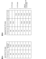
- Figure 2A shows an example of a DCI-based joint DL/UL TCI status indication.
- a TCI status ID indicating the joint DL/UL TCI status is associated with the value of the TCI field for the joint DL/UL TCI status indication.
- FIG. 2B shows an example of a DCI-based separate DL/UL TCI status indication.
- At least one TCI status ID is associated with the value of the TCI field for the separate DL/UL TCI status indication: a TCI status ID indicating a DL-only TCI status and a TCI status ID indicating a UL-only TCI status.
- TCI field values 000 to 001 are associated with only one TCI status ID for DL
- TCI field values 010 to 011 are associated with only one TCI status ID for UL
- TCI field values 100 to 111 are associated with both one TCI status ID for DL and one TCI status ID for UL.
- the unified/common TCI state may mean the Rel. 17 TCI state indicated using (Rel. 17) DCI/MAC CE/RRC (indicated Rel. 17 TCI state).
- TCI state indicates whether or not TCI is mapped to multiple types of signals (channels/RS).
- unified/common TCI state TCI state applicable to multiple types of signals (channels/RS)
- TCI state for multiple types of signals channels/RS
- the indicated Rel. 17 TCI state may be shared with at least one of the UE-specific reception on PDSCH/PDCC (updated using Rel. 17 DCI/MAC CE/RRC), PUSCH of dynamic grant (DCI)/configured grant, and multiple (e.g., all) dedicated PUCCH resources.
- the TCI state indicated by the DCI/MAC CE/RRC may be referred to as the indicated TCI state, the unified TCI state.
- a TCI state other than the unified TCI state may refer to a Rel. 17 TCI state configured using the (Rel. 17) MAC CE/RRC (configured Rel. 17 TCI state).
- the configured Rel. 17 TCI state, the configured TCI state, a TCI state other than the unified TCI state, and a TCI state applied to a specific type of signal (channel/RS) may be interpreted as being mutually interchangeable.
- the configured Rel. 17 TCI state may not be shared with at least one of the UE-specific reception in the PDSCH/PDCC (updated using the Rel. 17 DCI/MAC CE/RRC), the PUSCH of the dynamic grant (DCI)/configured grant, and multiple (e.g., all) dedicated PUCCH resources.
- the configured Rel. 17 TCI state may be configured by the RRC/MAC CE for each CORESET/resource/resource set, and may not be updated even if the indicated Rel. 17 TCI state (common TCI state) described above is updated.
- the indicated TCI state by the MAC CE/DCI may apply to the following channels/RS:
- CORESET0 follows the TCI state activated by the MAC CE or is QCL'd with SSB.
- the indicated TCI state For a CORESET with index other than 0 with USS/CSS type 3, the indicated TCI state always applies.
- the indicated TCI state applies. Otherwise, the configured TCI state for that CORESET applies to that CORESET.
- CSI-RS For an A-CSI-RS for CSI acquisition or beam management, if followUnifiedTCIState is set (for the CORESET of the PDCCH that triggers that A-CSI-RS), the indicated TCI state applies. For other CSI-RSs, the configured TCI state for that CSI-RS applies.
- TCI State Switching (TCI State Switching) Rel. 15/16 specifies a delay time for switching the active TCI state for a UE configured with one or more TCI states in the serving cell.
- the TCI status is known if the following conditions 0-5 are satisfied:
- TCI state is unknown means that the TCI state is not known.
- a known TCI state may be referred to as a "Known TCI State,” and an unknown TCI state may be referred to as an "Unknown TCI State.”
- the target TCI state (the TCI state to which the switching is made) is a known TCI state
- the UE receives a physical downlink shared channel (PDSCH) including a TCI state activation command (TCI state indication) in slot n
- the UE receives a physical downlink control channel (PDCCH) in the target TCI state of the serving cell in which the TCI state switching has occurred in the first slot after slot n+T HARQ +3N subframe, ⁇ slot +TO k *(T first - SSB + T SSB-proc )/(NR slot length).
- the UE can receive the PDCCH in the old (pre-switching) TCI state up to slot n+T HARQ +3N subframe, ⁇ slot .
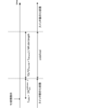
- the TCI state applied by the UE is undefined (see FIG. 3).
- T HARQ indicates the timing from the transmission of the downlink data signal (e.g., PDSCH) to the acknowledgement information (e.g., HARQ-ACK information).
- N subframe, ⁇ slot indicates the number of slots per subframe for the subcarrier setting ⁇ .
- T first-SSB is the time from the UE decoding the MAC CE command used for TCI state activation to the first SSB transmission.
- T SSB-proc is 2 ms.
- TO k is 1 if the target TCI state is not included in the list of active TCI states for PDSCH, and 0 otherwise.
- NR slot length indicates the length of the slot.
- FIG 4 shows an example of the TCI state defined up to Rel. 16.
- the TCI state of the PDCCH indicates the relationship between the demodulation reference signal (DMRS) for the PDCCH and the QCL type A/D of the TRS (or CSI-RS, TRS#1 in this case).
- the TCI state of the TRS indicates the relationship between the TRS, the SSB (SSB#1 in this case), and the QCL type C/D.
- the UE when the UE receives a PDSCH including a TCI state activation command in slot n, it receives a PDCCH in the target TCI state of the serving cell where the TCI state switching occurred in the first slot after slot n + T HARQ + 3N subframe, ⁇ slot + T L1-RSRP + TO uk * (T first-SSB + T SSB-proc ) / (NR slot length). Also, the UE can receive a PDCCH in the old (pre-switching) TCI state up to slot n + T HARQ + 3N subframe, ⁇ slot .
- TO uk is 1 for L1-RSRP measurements using CSI-RS or for switching of TCI states with QCL types other than QCL type D.
- TO uk is 0 for switching of TCI states with at least QCL type D and for L1-RSRP measurements using SSB.
- T first-SSB is the time to the first SSB transmission after the L1-RSRP measurement when switching the TCI state to which at least QCL type D is set, or T first-SSB is the time to the first SSB transmission after the UE decodes a MAC CE command used for activation of a TCI state other than QCL type D.
- T L1-RSRP is the time associated with the received power measurement.
- T L1-RSRP is 0 in frequency range (FR) 1 or in FR2 where QCL type D is not configured. Otherwise, it is the time required for determination/refinement of the receive beam in FR2.
- DCI downlink control information
- the target TCI state is a known TCI state
- the higher layer parameter tci-PresentInDCI for CORESET to schedule PDSCH in slot n is set to enabled
- the UE receives the PDSCH in the target TCI state of the serving cell where the TCI state switching occurred in the first slot after slot n+timeDurationForDCI.
- timeDurationForDCI is the time required for receiving the PDCCH and applying spatial relationship/QCL information (spatial QCL information) to receiving the DCI for the PDSCH.
- the UE when RRC signaling is used for TCI state switching (RRC based TCI state switch) and the target TCI state is a known TCI state, when the UE receives a PDSCH carrying an RRC activation command for the TCI state in slot n, it receives a PDCCH for the target TCI state of the serving cell in which the TCI state switching occurred in the first slot after slot n + (T RRC_processing + TO k * (T first-SSB + T SSB-proc ))/(NR slot length).
- T RRC_processing is the delay related to the RRC process (RRC processing delay)
- T first-SSB is the time until the first SSB transmission after the UE's RRC process
- T SSB-proc , TO k , and (NR slot length) are the same as in the known TCI state in TCI state switching using MAC CE.
- the UE when RRC signaling is used for TCI state switching (RRC based TCI state switch) and the target TCI state is unknown TCI state, when the UE receives a PDSCH transmitting an RRC activation command for the TCI state in slot n, it receives a PDCCH for the target TCI state of the serving cell in which the TCI state switching occurred in the first slot after slot n + (T RRC_processing + T L1-RSRP + TO uk * (T first-SSB + T SSB-proc ))/(NR slot length).
- T RRC_processing is the delay for the RRC process (RRC processing delay).
- T SSB-proc , TO uk and (NR slot length) are the same as in the unknown TCI state in TCI state switching using MAC CE.
- T first-SSB is the time to the first SSB transmission after the L1-RSRP measurement when switching the TCI state to which at least QCL type D is set, or T first-SSB is the time to the first SSB transmission after the UE decodes a MAC CE command used for activation of a TCI state other than QCL type D.
- Rel. 17 specifies delay times for switching unified TCI states.
- the specified delay time may be applied.
- this delay time also applies to all lists of multiple serving cells in simultaneous TCI update lists for multiple CCs/cells (e.g., simultaneousU-TCI-UpdateList1, simultaneousU-TCI-UpdateList2, simultaneousU-TCI-UpdateList3, simultaneousU-TCI-UpdateList4).
- the delay may be applied, provided that the following conditions are met:
- the active BWP of the serving cell and the cell of the additional PCI are the same.
- the center frequency, subcarrier spacing (SCS) and system frame number (SFN) offset of the cell of the additional PCI are the same as the serving cell.
- SCS subcarrier spacing
- SFN system frame number
- a cell in an additional PCI may be known if the following conditions are met: The UE has sent a valid L3 measurement report for a cell of an additional PCI in the last 5 seconds before the L1-RSRP measurement is configured. The timing offset between the serving cell and the cell of the additional PCI is within the CP of the corresponding SCS.
- the additional PCI cell may be unknown.
- a DL TCI state in a unified TCI state being known may satisfy the following conditions: - From the last transmission of the RS resource used for reporting the L1-RSRP measurement of the target DL TCI state until the switching of the active DL TCI state is completed, the RS resource for the L1-RSRP measurement is an RS of the target DL TCI state or an RS that has a QCL relationship with the target DL TCI state.
- a DL TCI state switch command is received within 1280 ms of the last transmission of RS resources for beam reporting or measurement.
- the UE has sent at least one L1-RSRP report for the target DL TCI state prior to the DL TCI state switch indication.
- - DL TCI state detection remains possible during DL TCI state switching. During the DL TCI state switching period, detection of the SSB associated with the DL TCI state remains possible.
- the signal to noise ratio (SNR) in DL TCI state is -3 dB or more.
- the SSB may be associated with the PCI of the serving cell or a PCI different from the serving cell PCI.
- the DL TCI status may be unknown.
- the UE may not be expected to receive in DL based on the target TCI state before completing the DL and UL TCI state switch.
- the target TCI state (the TCI state to which the switching is made) is a known TCI state
- the UE receives a PDSCH including a TCI state activation command (TCI state indication) in slot n
- the UE receives a physical downlink control channel (PDCCH) in the target TCI state of the serving cell in which the TCI state switching occurred in the first slot after slot n + T HARQ + 3N subframe, ⁇ slot + TO k * (T first- SSB + T SSB-proc ) / (NR slot length).
- the UE can receive the UE-specific PDSCH / PDCCH using the old (before switching) TCI state up to slot n + T HARQ + 3N subframe , ⁇ slot.
- the TCI state that the UE applies is not specified.
- T HARQ indicates the timing from the transmission of the downlink data signal (e.g., PDSCH) to the acknowledgement information (e.g., HARQ-ACK information).
- N subframe, ⁇ slot indicates the number of slots per subframe for the subcarrier setting ⁇ .
- T first-SSB is the time from the UE decoding the MAC CE command used for TCI state activation to the first SSB transmission.
- T SSB-proc is 2 ms.
- TO k is 1 if the target TCI state is not included in the list of active TCI states for PDSCH, and 0 otherwise.
- NR slot length indicates the length of the slot.
- TO uk is 1 for L1-RSRP measurements using CSI-RS or for switching of TCI states with QCL types other than QCL type D.
- TO uk is 0 for switching of TCI states with at least QCL type D and for L1-RSRP measurements using SSB.
- this delay time also applies to all lists of multiple serving cells in simultaneous TCI update lists for multiple CCs/cells (e.g., simultaneousU-TCI-UpdateList1, simultaneousU-TCI-UpdateList2, simultaneousU-TCI-UpdateList3, simultaneousU-TCI-UpdateList4).
- the UE may not be expected to transmit in the UL before the DL and UL TCI state switch is completed.
- T target-PL-RS is the time to the first transmission of pathloss RS after L1-RSRP measurement when the target TCI state is unknown
- T target-PL-RS is the time to the first transmission of pathloss RS after the MAC CE command is decoded by the UE when the target TCI state is known.
- T target-PL-RS is the period of the target PL-RS that is an SSB or NZP CSI-RS if the PL-RS is associated with the serving cell.
- T target-PL-RS is the period of the PL-RS that is an SSB if the PL-RS is associated with a different PCI than the serving cell.
- T L1-RSRP is the time associated with the received power measurement.
- T L1-RSRP is 0 in frequency range (FR) 1 or in FR2 where QCL type D is not configured. Otherwise, it is the time required for determination/refinement of the receive beam in FR2.
- Event-based beam reporting may be called event triggered beam reporting, and may mean UE-initiated beam reporting.
- the unified TCI framework defined in Rel. 17/18 is expected to support both joint (DL/UL) TCI and separate (DL/UL) TCI operation modes.
- the quality of the UL beam may depend on at least one of the received power (e.g., RSRP) and factors related to the MPE (e.g., Power-management Maximum Power Reduction (P-MPR)).
- RSRP received power
- P-MPR Power-management Maximum Power Reduction
- the UE may determine independent (different) status in DL and UL.
- the UE may determine a different new beam for DL and a new beam for UL. Also, for example, no DL beam update may be required, but UL beam update may be required due to MPE issues.
- group-based beam reporting for DL was considered and supported.
- the reported beam pair may be a beam pair that is received simultaneously.
- the inventors therefore came up with a way to solve these problems.
- A/B and “at least one of A and B” may be interpreted as interchangeable. Also, in this disclosure, “A/B/C” may mean “at least one of A, B, and C.”
- Radio Resource Control RRC
- RRC parameters RRC parameters
- RRC messages higher layer parameters, fields, information elements (IEs), settings, etc.
- IEs information elements
- CE Medium Access Control
- update commands activation/deactivation commands, etc.
- the higher layer signaling may be, for example, any one of Radio Resource Control (RRC) signaling, Medium Access Control (MAC) signaling, broadcast information, other messages (e.g., messages from the core network such as positioning protocols (e.g., NR Positioning Protocol A (NRPPa)/LTE Positioning Protocol (LPP)) messages), or a combination of these.
- RRC Radio Resource Control
- MAC Medium Access Control
- LPP LTE Positioning Protocol
- the MAC signaling may use, for example, a MAC Control Element (MAC CE), a MAC Protocol Data Unit (PDU), etc.
- the broadcast information may be, for example, a Master Information Block (MIB), a System Information Block (SIB), Remaining Minimum System Information (RMSI), Other System Information (OSI), etc.
- MIB Master Information Block
- SIB System Information Block
- RMSI Remaining Minimum System Information
- OSI System Information
- the physical layer signaling may be, for example, Downlink Control Information (DCI), Uplink Control Information (UCI), etc.
- DCI Downlink Control Information
- UCI Uplink Control Information
- multi (multiple) TRP, multi TRP system, multi TRP transmission, and multi PDSCH may be interpreted as interchangeable.
- a single DCI, a single PDCCH, multiple TRP based on a single DCI, activating two TCI states on at least one TCI code point, mapping at least one code point of a TCI field to two TCI states, and setting a specific index (e.g., a TRP index, a CORESET pool index, or an index corresponding to a TRP) for a specific channel/CORESET may be interpreted as interchangeable.
- a single TRP, a channel/signal using a single TRP, a channel using one TCI state/spatial relationship, multi-TRP not being enabled by RRC/DCI, multiple TCI states/spatial relationships not being enabled by RRC/DCI, a CORESETPoolIndex value of 1 not being set for any CORESET, and no code point in the TCI field being mapped to two TCI states may be read as interchangeable.
- TRP#2 (second TRP)
- single DCI sDCI
- single PDCCH multi-TRP system based on single DCI
- sDCI-based MTRP multi-TRP system based on single DCI
- activation of two TCI states on at least one TCI codepoint may be read as interchangeable.
- event-triggered beam reporting may simply be referred to as beam reporting/CSI reporting/L1 beam reporting.
- Each embodiment/option in the present disclosure may be used alone or in combination.
- Each embodiment/option in the present disclosure may be switched using higher layer signaling (RRC/MAC CE) or may be set/instructed based on reported UE capability information.
- RRC/MAC CE higher layer signaling
- Each embodiment of the present disclosure may be applied, for example, to at least one of the following cases 1 and 2: - [Case 1]: L1-RSRP/SINR beam reporting including serving cell PCI/additional PCI (e.g., L1-RSRP/SINR beam reporting including serving cell/additional PCI cells for Rel. 18 L1/L2 mobility with L1/L2 inter-cell mobility/M-TRP inter-cell/cell switching).
- [Case 2] L1-RSRP/SINR beam report including serving cell PCI only.
- the UE may report the measurement results (e.g., L1-RSRP/L1-SINR) to the NW (e.g., base station).
- the NW e.g., base station
- the particular event may be, for example, at least one of an event related to the serving cell and/or the additional cell, and an event related to a beam report including at least one of the PCI of the serving cell and/or the PCI of the additional cell.
- the event may mean, for example, an event related to a serving cell and an additional cell, and an event related to a beam report including a PCI of the serving cell and a PCI of the additional cell.
- a beam report (e.g., aperiodic CSI report) may be triggered by reusing one or more existing events of Radio Resource Management (RRM) (e.g., at least one of the following events A2 to A6 and I1). That is, when at least one of the following events A2 to A6 and I1 occurs (when the condition of the event is satisfied), both the RRM report and the CSI report may be triggered, and the UE may transmit both the RRM report and the CSI report.
- RRM Radio Resource Management
- RRM reports may be read as L3 measurement reports and vice versa.
- FIG. 5 is a flowchart showing an example of the process of an event-triggered beam report.
- the UE determines whether an event (e.g., at least one of the following events A2 to A6 and I1) has occurred (S1). If YES in S1, the UE transmits an aperiodic CSI report (and an RRM report) (S2), and if NO, ends the process related to the 0th embodiment.
- the process of FIG. 5 may be repeatedly performed at predetermined intervals.
- aperiodic CSI reporting being triggered and a UE transmitting an aperiodic CSI report may be interchangeable.
- CSI reporting, L1 beam reporting, and beam reporting may be interchangeable.
- the measurement result may be at least one of RSRP (L1-RSRP/L3-RSRP), RSRQ, and SINR (RS-SINR).
- RSRP L1-RSRP/L3-RSRP
- RSRQ RSRQ
- SINR SINR
- SpCell means a special cell and may mean at least one of Primary Cell (PCell) and Primary Secondary Cell (PSCell).
- a parameter corresponding to hysteresis may be added/subtracted from the measurement result.
- Each threshold may be the same or different.
- a neighboring cell may be a non-serving cell.
- Event A2 The serving cell measurement result is worse than a threshold.
- Event A3 The measurement result of the neighboring cell (a value obtained by adding an offset to the measurement result) is better than the measurement result of the SpCell (a value obtained by adding an offset to the measurement result).
- Event A4 The measurement result of the neighboring cell (the measurement result plus an offset) is better than the threshold.
- Event A5 The measurement result of the SpCell is worse than a first threshold, and the measurement result of the neighboring cell (a value obtained by adding an offset to the measurement result) is better than a second threshold.
- Event A6 The measurement result of the neighboring cell (a value obtained by adding an offset to the measurement result) is better than the measurement result of the serving cell (Secondary Cell (SCell)) (a value obtained by adding an offset to the measurement result).
- Event I1 The interference measurement is higher than the threshold.
- Option 0-1 simplifies configuration by allowing the RRM report trigger to be reused as the beam report trigger.
- One or more new events may be defined to trigger aperiodic L1 beam reporting (CSI reporting).
- the events may be similar to the above events A2 to A6 and I1 that also apply to triggering RRM reporting, but may differ from any of the events A2 to A6 and I1 (triggering RRM reporting) in at least one of the following options 0-2-1 to 0-2-4.
- the thresholds may be different, i.e., events A2 to A6 and I1 may be used for L1 beam reporting (CSI reporting) with different thresholds than the events for RRM reporting.
- the event may be generated based on the measurement result of the reference signal received power at layer 1 (L1-RSRP). That is, the comparison may be based on L1-RSRP instead of L3-RSRP. Or, a new filtered L1-RSRP may be applied, whose time scale (period of update/measurement) is between L1-RSRP and L3-RSRP (or is the same as L1-RSRP or L3-RSRP). Or, other metrics may be applied, e.g., L1-SINR, L3-RSRQ, etc. For example, the following event A2′ may be applied as a new event: Event A2': The L1-RSRP measurement result of the serving cell is worse than a threshold.
- Event A4' The measurement result of one beam from a neighboring cell is better than the threshold.
- Event A4′′ A statistic (e.g. average, sum, etc.) of measurement results of multiple beams (e.g. best X beams) is better than a threshold.
- X may be fixed or configurable by higher layer signaling, etc.
- the number of beams that satisfy a condition may be considered. For example, if X beams satisfy event A4′ (if the measurement results of X beams from neighbor cells are better than a threshold), the UE may report CSI.
- A4''' is a possible event that combines 0-2-2 and 0-2-3. Also, A4'''' is a possible event that combines 0-2-2, 0-2-3, and 0-2-4: Event A4''': The L1-RSRP measurement result of one beam from a neighboring cell is better than a threshold. Event A4'''': The L1-RSRP of each of the X beams from the neighboring cells is better than a threshold.
- Option 0-2 allows for faster CSI reporting compared to using existing RRM reporting events using RRC.
- Existing events for RRM reporting may be combined with one or more events of option B. For example, a CSI report may be triggered if both event A4 and new event A4''' occur.
- Two or more events from options 0-2 may be combined. For example, a CSI report may be triggered if both event A2' and new event A4''' are met.
- the event may mean, for example, an event related to only the serving cell, or an event related to a beam report including only the PCI of the serving cell.
- One or more new events may be defined to trigger aperiodic L1 beam reporting (CSI reporting), which may be at least one of the following events B2 to B6 and K1:
- Event B2 The measurement result of the current beam is worse than the threshold.
- Event B3 The measurement result of the other beam (the measurement result plus an offset) is better than the measurement result of the current beam (the measurement result plus an offset).
- Event B4 The measurement result of the other beam (the measurement result plus an offset) is better than the threshold value.
- Event B5 The measurement of the current beam is worse than a first threshold and the measurement of the other beam (the measurement plus an offset) is better than a second threshold.
- Event B6 The measurement result of the current beam (the value of the measurement result plus an offset) is worse than the threshold, and the measurement result of another beam (the value of the measurement result plus an offset) is better than the measurement result of the current beam (the value of the measurement result plus an offset).
- Event K1 The interference measurement is higher than the threshold.
- the names/symbols of events in this disclosure are merely examples and are not limited to these examples.
- the name of an event for case 2 and the name of the event for case 1 that corresponds (in terms of number) may be the same.
- a duration/counter during which the event (conditions) are met may be specified.
- the UE/NW may determine that the conditions of each event are met when at least one of the conditions of each of the above events meets a condition related to a specific duration/counter. For example, the UE may determine that the conditions of the above event B3 are met when the measurement results of the other beam are better than the measurement results of the current beam in a time window of 100 ms. Also, for example, the UE may determine that the conditions of the above event B3 are met when the measurement results of the other beam are better than the measurement results of the current beam 10 times per multiple samples.
- current beam may refer to, for example, an SSB/CSI-RS that is QCL-related (QCLed) with the PDCCH.
- the PDCCH may be, for example, a PDCCH corresponding to a CORESET determined by a particular rule/higher layer parameter setting.
- the CORESET may be, for example, a CORESET with a particular (e.g., lowest/highest) CORESET ID.
- the CSI-RS may be, for example, a periodic/semi-persistent/aperiodic CSI-RS.
- the SSB/CSI-RS may be, for example, limited to a periodic CSI-RS/SSB.
- the "current beam” may be, for example, an indicated TCI state (joint/DL TCI state) in the current unified TCI state.
- the "current beam” may be, for example, a QCL source RS for the current indicated TCI state.
- the "current beam” may be, for example, a beam/resource index (e.g., CRI/SSBRI) reported in a particular (e.g., latest) L1-RSRP/L1-SINR.
- a beam/resource index e.g., CRI/SSBRI
- other beams may be, for example, beams/SSB/CSI-RS/TCI states other than the "current beam.”
- a set of multiple beams may be configured for the UE.
- the UE may select/determine an "other beam” from the set.
- “worse/better” may mean, for example, lower/higher measurement results (e.g., RSRP/SINR/RSRQ).
- the thresholds may be predefined in the specification, may be configured/indicated/notified using higher layer signaling (RRC/MAC CE)/DCI, may be reported by UE capabilities, or may be determined by a combination of these.
- the thresholds may be reused from existing thresholds (e.g., thresholds used in RRM/Case 1).
- the offset for the threshold may be predefined in the specification, may be configured/indicated/notified using higher layer signaling (RRC/MAC CE)/DCI, may be reported by UE capabilities, or may be determined by a combination of these.
- RRC/MAC CE higher layer signaling
- UE initiated beam reporting, event triggered beam reporting, event based beam reporting, and event based beam reporting may be interpreted as interchangeable.
- reported beam reporting beam
- UE reporting beam may be interpreted interchangeably.
- the first embodiment relates to events related to event triggered beam reporting.
- the UE may be configured to operate in a unified TCI state (e.g., joint TCI mode/separate TCI mode).
- a unified TCI state e.g., joint TCI mode/separate TCI mode
- At least one of the events in the event triggered beam report may be an event based on MPE related parameter(s).
- "worse/better" for the at least one event may be determined based on a parameter related to the MPE (e.g., P-MPR).
- P-MPR a parameter related to the MPE
- "worse/better" for at least one event may be determined based on a parameter related to MPE (e.g., P-MPR) independent of the measurement results (e.g., RSRP/SINR/RSRQ).
- P-MPR a parameter related to MPE
- RSRP/SINR/RSRQ a parameter related to MPE independent of the measurement results
- "worse/better" for the at least one event may be determined based on a parameter related to MPE (e.g., P-MPR) along with measurement results (e.g., RSRP/SINR/RSRQ).
- P-MPR a parameter related to MPE
- measurement results e.g., RSRP/SINR/RSRQ
- a beam with a higher P-MPR may mean “worse” and a beam with a lower P-MPR may mean “better.”
- the UE may perform beam reporting for both DL and UL beams.
- the beam report may be referred to, for example, as a joint DL/UL beam report.
- the event that triggers a beam report may be common to DL beams and UL beams.
- the event that triggers a beam report does not have to be different for DL beams and UL beams.
- the reported beam may apply to both DL and UL.
- the UE may provide beam reporting for at least one of a DL beam and/or a UL beam.
- the beam report may be referred to as, for example, a separate DL/UL beam report.
- Events that trigger DL beam reports and events that trigger UL beam reports may be defined/used separately.
- a beam report may be triggered when at least one of an event that triggers a DL beam report and an event that triggers a UL beam report occurs.
- a beam report may be triggered.
- a beam report may be triggered when either an event that triggers a DL beam report or an event that triggers a UL beam report occurs.
- the UE may report DL/UL beams.
- the UE may always decide to report on both the DL beam and the UL beam.
- a specific beam may be reported.
- the particular beam may be, for example, a new beam for DL/UL that meets certain conditions for the event.
- the particular beam may be, for example, the best beam.
- the best beam may be at least one of a beam with a higher measurement result (e.g., L1-RSRP/L1-SINR/L3-RSRP/L3-RSRQ/other metric) and a beam with a lower MPE-related parameter (e.g., P-MPR) and/or other metric.
- a beam with a higher measurement result e.g., L1-RSRP/L1-SINR/L3-RSRP/L3-RSRQ/other metric
- a beam with a lower MPE-related parameter e.g., P-MPR
- the particular beam may include, for example, the current beam and its quality (e.g., L1-RSRP/L1-SINR/L3-RSRP/L3-RSRQ/MPE-related parameters (e.g., P-MPR)/other metrics).
- the current beam e.g., L1-RSRP/L1-SINR/L3-RSRP/L3-RSRQ/MPE-related parameters (e.g., P-MPR)/other metrics).
- a specific beam may be reported.
- the particular beam may be, for example, the current DL/UL beam.
- the particular beam may be, for example, the best beam.
- the best beam may be at least one of a beam with a higher measurement result (e.g., L1-RSRP/L1-SINR/L3-RSRP/L3-RSRQ/other metric) and a beam with a lower MPE-related parameter (e.g., P-MPR) and/or other metric.
- a beam with a higher measurement result e.g., L1-RSRP/L1-SINR/L3-RSRP/L3-RSRQ/other metric
- a beam with a lower MPE-related parameter e.g., P-MPR
- the number of beam reports for DL/UL may be a predefined value (e.g., a fixed value) or may be set.
- X1 beams may be reported for DL and X2 beams may be reported for UL.
- X1 and X2 may be fixed values or may be set.
- X1 and X2 may be the same value or different values.
- At least one of X1 and X2 may be 1, or may be 2 or more.
- the total number of beam reports may be defined as X1+X2.
- a beam report may be triggered when at least one of an event that triggers a DL beam report and an event that triggers a UL beam report occurs.
- the UE may report DL/UL beams.
- the UE may perform a DL beam report.
- the UE may perform a UL beam report.
- the UE may perform a DL beam report and a UL beam report.
- a specific beam may be reported.
- the particular beam may be, for example, a new beam that meets certain conditions in the event.
- the particular beam may be, for example, the best beam.
- the best beam may be at least one of a beam with a higher measurement result (e.g., L1-RSRP/L1-SINR/L3-RSRP/L3-RSRQ/other metric) and a beam with a lower MPE-related parameter (e.g., P-MPR) and/or other metric.
- a beam with a higher measurement result e.g., L1-RSRP/L1-SINR/L3-RSRP/L3-RSRQ/other metric
- a beam with a lower MPE-related parameter e.g., P-MPR
- the particular beam may include, for example, the current beam and its quality (e.g., L1-RSRP/L1-SINR/L3-RSRP/L3-RSRQ/MPE-related parameters (e.g., P-MPR)/other metrics).
- the current beam e.g., L1-RSRP/L1-SINR/L3-RSRP/L3-RSRQ/MPE-related parameters (e.g., P-MPR)/other metrics).
- a specific beam may be reported.
- the particular beam may be, for example, the current DL/UL beam.
- the particular beam may be, for example, the best beam.
- the best beam may be at least one of a beam with a higher measurement result (e.g., L1-RSRP/L1-SINR/L3-RSRP/L3-RSRQ/other metric) and a beam with a lower MPE-related parameter (e.g., P-MPR) and/or other metric.
- a beam with a higher measurement result e.g., L1-RSRP/L1-SINR/L3-RSRP/L3-RSRQ/other metric
- a beam with a lower MPE-related parameter e.g., P-MPR
- the number of beam reports for DL/UL may be a predefined value (e.g., a fixed value) or may be set.
- X1 beams may be reported for DL and X2 beams may be reported for UL.
- X1 and X2 may be fixed values or may be set.
- X1 and X2 may be the same value or different values.
- At least one of X1 and X2 may be 1, or may be 2 or more.
- the total number of beam reports may be variable. This option may only be applied when beam reports are transmitted in a specific signal (e.g., MAC CE).
- the application of either of the above options 1-2-1 and 1-2-2 may be reported by the UE, may be configured by the network/base station, or may be specified in the UE capabilities.
- decision to apply either option 1-1 or 1-2 above may be predefined in the specifications, may be set using higher layer signaling, may be based on reported UE capability information, or may be determined by a combination of these.
- option 1-1 may be applied.
- option 1-2 may be applied.
- This option describes a MAC CE for beam reporting.
- the MAC CE described in this option can be appropriately applied not only to the first embodiment but also to the second to sixth embodiments.
- MAC CE may be defined, respectively.
- the MAC CE for option 1-1 may be different from the MAC CE for option 1-2.
- the MAC CE for option 1-1 may have different LCIDs.
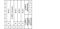
- Figure 6 shows an example of a beam reporting MAC CE for option 1-1.
- the field corresponding to the measurement result of the best (top-ranked) beam may be specified with a first number of bits (e.g., 7 bits).
- the field may indicate the absolute value of the measurement result.
- a field corresponding to the measurement results of beams other than the best beam may be specified with a second number of bits (e.g., 4 bits).
- the field may indicate a relative value/differential value with respect to the measurement result of the best beam.
- a field corresponding to the measurement results of beams other than the best beam may be specified with a first number of bits (e.g., 7 bits).
- the field may indicate the absolute value of the measurement result.
- the " Ci " field may be represented by 1 bit.
- the " Ci " field indicates a first value (e.g., 0), it may indicate that the corresponding beam is not reported.
- a second value e.g., 1
- the measurement results and RS ID of the second beam, the measurement results and RS ID of the third beam, and the measurement results and RS ID of the fourth beam may be reported in the MAC CE.
- Figure 7 shows an example of a beam reporting MAC CE for option 1-2. The following explains the differences from the MAC CE for option 1-1.
- the "C i " field included in the MAC CE may be represented by 2 bits.
- the "C i " field indicates a first value (eg, 00), it may indicate that no reporting of the corresponding beam is performed.
- the "C i " field indicates a second value (eg, 01), it may indicate that only reporting of the corresponding DL beam is performed.
- the "C i " field indicates a third value (eg, 10), it may indicate that only reporting of the corresponding UL beam is performed.
- the "C i " field indicates a fourth value (eg, 11), it may indicate that both the corresponding DL beam and UL beam are reported.
- the MAC CE for the above-mentioned Option 1-1/1-2 does not include a "C i " field corresponding to the best beam.
- the MAC CE may be used to report on at least one beam.
- the "C i " field in the MAC CE for option 1-1/1-2 described above may be a field for indicating that there is no beam to report (eg, a beam with good measurement results).
- a common MAC CE may be defined for the above options 1-1 and 1-2.
- the MAC CE for option 1-1 and the MAC CE for option 1-2 may be the same.
- the MAC CE for option 1-1 and the MAC CE for option 1-2 may have the same LCID.
- the common MAC CE may be, for example, the MAC CE for option 1-2 in option 1-3-1 above.
- option 1-1 When option 1-1 is applied and the MAC CE for option 1-2 is used as the MAC CE for beam reporting, for example, fields related to DL may be used/reported, and fields related to UL may not be used/reported.
- the number of beams reported in an event-based beam report may be determined using higher layer signaling (e.g., RRC signaling).
- RRC signaling e.g., RRC signaling
- the UE may report a specific value (e.g., the lowest/highest codepoint of the measurement result (e.g., L1-RSRP) value).
- a specific value e.g., the lowest/highest codepoint of the measurement result (e.g., L1-RSRP) value.
- the number of beams reported in an event-based beam report may be the top N number determined by the UE from the number set by higher layer signaling (e.g., RRC signaling).
- higher layer signaling e.g., RRC signaling
- the UE may report two beams in the event-based beam report.
- the content and method of DL and UL beam reports can be appropriately specified.
- This embodiment relates to the beam switching method according to the first embodiment.
- This embodiment may, for example, be adapted to the beam reporting described in option 1-2 (or 1-1) in the first embodiment above.
- the UE may update/change/adapt beam (QCL assumption/TCI state/spatial relationship) based on event triggered beam reports.
- the UE may receive a response (e.g., an acknowledgement (ACK) or a negative acknowledgement (NACK)) to the beam report from the NW (base station).
- a response e.g., an acknowledgement (ACK) or a negative acknowledgement (NACK)
- ACK acknowledgement
- NACK negative acknowledgement
- the UE may retransmit the beam report after the end of the first period, or may transmit a new beam report different from the beam report that was transmitted.
- the beam report may be retransmitted up to a certain number of times.
- the first period and the specific number of times may be specified in advance in the specifications, may be configured/instructed/notified to the UE using higher layer signaling (RRC/MAC CE)/DCI, or may be reported by UE capability information.
- RRC/MAC CE higher layer signaling
- the response to the beam report may be transmitted, for example, using DCI.
- a response to the beam report may be sent using a DCI format that has the same HARQ process number as the initial PUSCH (transmitting the MAC CE) and has a toggled value for the New Data Indicator (NDI) field.
- NDI New Data Indicator
- the response to the beam report may indicate any one of the multiple beams/RS. This configuration allows for more flexible beam updates.
- the response to the beam report may include N bits of information indicating one of the multiple beams/RSs.
- the UE may receive one bit of information indicating a response to the beam report. In this case, the UE may decide to update/change to the best beam among the N beams/RSs.
- the UE may update/change/apply the beam (QCL assumption/TCI state/spatial relationship) after a certain period of time has elapsed after receiving a response to the beam report (or after sending the beam report).
- the specific period may be specified in advance in the specifications, may be configured/instructed/notified to the UE using higher layer signaling (RRC/MAC CE)/DCI, or may be reported by UE capability information.
- RRC/MAC CE higher layer signaling
- the particular period may be indicated, for example, in a particular unit of time (e.g., Xms/symbol/slot/subslot).
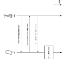
- FIG. 8 is a diagram showing an example of beam updating according to the second embodiment.
- the UE receives a setting/instruction regarding the unified TCI state (step S800).
- the UE performs an event-triggered beam report to the NW (base station) (step S801).
- the UE receives a response to the beam report from the NW (step S802).
- the UE performs a beam update based on the beam report (step S803).
- the UE may further receive additional instructions from the network/base station.
- a response e.g., an ACK
- the additional instructions may be transmitted, for example, using DCI.
- the DCI may be, for example, a DCI that schedules a UL/DL channel (e.g., PUSCH/PDSCH), or may be a specific DCI for instructions regarding event-triggered beam reporting (e.g., an existing DCI format (a specific value of a specific field) or a new DCI format (DCI format 0_x/1_x/2_x/3_x (x is any integer))).
- a DCI that schedules a UL/DL channel e.g., PUSCH/PDSCH
- a specific DCI for instructions regarding event-triggered beam reporting e.g., an existing DCI format (a specific value of a specific field) or a new DCI format (DCI format 0_x/1_x/2_x/3_x (x is any integer)
- the instruction may indicate whether DL/UL beams are applied/updated.
- the instruction may indicate a response and application/update to a DL beam reported by the UE, but may not indicate a response and application/update to a UL beam reported (or not reported) by the UE.
- the instruction may indicate a response and application/update to a UL beam reported by the UE, but may not indicate a response and application/update to a DL beam reported (or not reported) by the UE.
- the indication may indicate a response and application/update to the DL beam and UL beam reported by the UE.
- beam switching/updating can be performed appropriately using beam reports.
- the third embodiment relates to events for event-triggered beam reporting when multi-TRP is used (multi-TRP framework).
- the UE may be configured/instructed to use N TRPs (N is an integer equal to or greater than 2).
- Events related to event triggered beam reporting may be determined for each TRP.
- the event related to the event-triggered beam reporting for a certain TRP may be, for example, at least one of the following events:
- Event 3A2 The measurement result of the current beam at the TRP is worse than the threshold.
- Event 3A3 The measurement result of a new beam of the TRP (the measurement result plus an offset) is better than the measurement result of a current beam of the TRP (the measurement result plus an offset).
- Event 3A4 The measurement result of the new beam of the TRP (the measurement result plus an offset) is better than the threshold.
- Event 3A5 The measurement result of the current beam of the TRP is worse than a first threshold, and the measurement result of the new beam of the TRP (the measurement result plus an offset) is better than a second threshold.
- Event 3A6 The measurement result of the current beam of the TRP is worse than the first threshold, and the measurement result of the new beam of the TRP (the measurement result plus an offset) is better than the measurement result of the current beam of the TRP (the measurement result plus an offset).
- Event 3I1 The interference measurement for the current beam of the TRP is higher than the threshold.
- the measurement result may be at least one of RSRP (L1-RSRP/L3-RSRP), RSRQ, and SINR (RS-SINR).
- a parameter corresponding to hysteresis may be added/subtracted from the measurement result.
- Each threshold value may be the same or different.
- the "current beam of the first TRP” may mean the first instruction (joint/separate (DL/UL)) TCI state
- the "current beam of the second TRP” may mean the second instruction (joint/separate (DL/UL)) TCI state.
- the "current beam of the first TRP” may mean the instruction (joint/separate (DL/UL)) TCI state corresponding to the CORESET pool index of a first value (e.g., 0), and the "current beam of the second TRP” may mean the instruction (joint/separate (DL/UL)) TCI state corresponding to the CORESET pool index of a second value (e.g., 1).
- “Current beam of the first TRP” may mean the beam reported for the first TRP in the latest beam report
- current beam of the second TRP may mean the beam reported for the second TRP in the latest beam report
- the "current beam of the first TRP" may mean the first default joint/DL/UL beam or the default joint/DL/UL beam for the first TRP. If a default beam is defined/set, the "current beam of the second TRP" may mean the second default joint/DL/UL beam or the default joint/DL/UL beam for the second TRP.
- a set of candidate beams may be configured for the UE. This configuration may be performed, for example, using higher layer signaling (RRC/MAC CE).
- RRC/MAC CE higher layer signaling
- the UE may select/determine a new beam from the set of configured candidate beams.
- the UE may follow at least one of options 3-1 and 3-2 below.
- One common candidate beam set may be configured for multiple (N) TRPs.
- the UE may select and report new beams independently for different TRPs. For example, the UE may select and report different new beams for different TRPs.
- a current beam in one TRP does not have to be reported as a new beam in other TRPs.
- a current beam in one TRP may be reported as a new beam in another TRP.
- Candidate beam sets may be set independently for multiple (N) TRPs.
- one candidate beam set may be configured for one TRP. If a UE uses N TRPs, it may be configured with N candidate beam sets.
- the new beam for each TRP may be selected from the set of candidate beams corresponding to each TRP.
- “worse” in the above events may mean, for example, lower measurement results (e.g., RSRP/SINR/RSRQ/other metrics) and/or higher MPE-related parameters (e.g., P-MPR)/other metrics.
- lower measurement results e.g., RSRP/SINR/RSRQ/other metrics
- MPE-related parameters e.g., P-MPR
- “(better)” in the above event may mean, for example, at least one of (a) higher measurement result (e.g., RSRP/SINR/RSRQ/other metric) and (a) lower MPE-related parameter (e.g., P-MPR)/other metric.
- a higher measurement result e.g., RSRP/SINR/RSRQ/other metric
- MPE-related parameter e.g., P-MPR
- the thresholds/offsets for the above events may be predefined in the specifications, may be set using higher layer signaling, may be reported by UE capabilities, or may be determined by a combination of these.
- the threshold/offset may be specified/set/reported/determined specifically for event-triggered beam reporting in a multi-TRP framework.
- the threshold/offset may be an existing threshold/offset (e.g., a threshold/offset used for RRM).
- events for event-triggered beam reporting can be appropriately defined when using multi-TRP.
- the fourth embodiment relates to the contents of event triggered beam reports when multi-TRP is used.
- a beam report may be triggered if at least one of the events described in the third embodiment occurs in at least one TRP.
- the UE may report beams for multiple (N) TRPs.
- Specific beams may be reported for TRPs where the event conditions are met.
- the particular beam may be, for example, a new beam that meets certain conditions in the event.
- the particular beam may be, for example, the best beam.
- the best beam may be at least one of a beam with a higher measurement result (e.g., L1-RSRP/L1-SINR/L3-RSRP/L3-RSRQ/other metric) and a beam with a lower MPE-related parameter (e.g., P-MPR) and/or other metric.
- a beam with a higher measurement result e.g., L1-RSRP/L1-SINR/L3-RSRP/L3-RSRQ/other metric
- a beam with a lower MPE-related parameter e.g., P-MPR
- the particular beam may include, for example, the current beam and its quality (e.g., L1-RSRP/L1-SINR/L3-RSRP/L3-RSRQ/MPE-related parameters (e.g., P-MPR)/other metrics).
- the current beam e.g., L1-RSRP/L1-SINR/L3-RSRP/L3-RSRQ/MPE-related parameters (e.g., P-MPR)/other metrics).
- Specific beams may be reported for TRPs where the event conditions are not met.
- the particular beam in question may be, for example, the current beam.
- the particular beam may be, for example, the best beam.
- the best beam may be at least one of a beam with a higher measurement result (e.g., L1-RSRP/L1-SINR/L3-RSRP/L3-RSRQ/other metric) and a beam with a lower MPE-related parameter (e.g., P-MPR) and/or other metric.
- a beam with a higher measurement result e.g., L1-RSRP/L1-SINR/L3-RSRP/L3-RSRQ/other metric
- a beam with a lower MPE-related parameter e.g., P-MPR
- the number of beam reports (e.g., number of beams) in each TRP may be a predefined value (e.g., a fixed value) or may be set.
- X beams may be reported for one TRP.
- X may be a fixed value or may be set.
- X may be 1 or a number greater than or equal to 2.
- the total number of beam reports may be specified/set as X ⁇ N (where N is the number of TRPs).
- the UE may report the beam for the TRP on which the event occurred.
- the UE may perform a beam report for the first TRP.
- the UE may perform a beam report for the second TRP.
- the UE may perform a beam report for the first TRP and a beam report for the second TRP.
- Specific beams may be reported for TRPs where the event conditions are met.
- the particular beam may be, for example, a new beam that meets certain conditions in the event.
- the particular beam may be, for example, the best beam.
- the best beam may be at least one of a beam with a higher measurement result (e.g., L1-RSRP/L1-SINR/L3-RSRP/L3-RSRQ/other metric) and a beam with a lower MPE-related parameter (e.g., P-MPR) and/or other metric.
- a beam with a higher measurement result e.g., L1-RSRP/L1-SINR/L3-RSRP/L3-RSRQ/other metric
- a beam with a lower MPE-related parameter e.g., P-MPR
- the particular beam may include, for example, the current beam and its quality (e.g., L1-RSRP/L1-SINR/L3-RSRP/L3-RSRQ/MPE-related parameters (e.g., P-MPR)/other metrics).
- the current beam e.g., L1-RSRP/L1-SINR/L3-RSRP/L3-RSRQ/MPE-related parameters (e.g., P-MPR)/other metrics).
- Specific beams may be reported for TRPs where the event conditions are not met.
- the particular beam in question may be, for example, the current beam.
- the particular beam may be, for example, the best beam.
- the best beam may be at least one of a beam with a higher measurement result (e.g., L1-RSRP/L1-SINR/L3-RSRP/L3-RSRQ/other metric) and a beam with a lower MPE-related parameter (e.g., P-MPR) and/or other metric.
- a beam with a higher measurement result e.g., L1-RSRP/L1-SINR/L3-RSRP/L3-RSRQ/other metric
- a beam with a lower MPE-related parameter e.g., P-MPR
- the number of beam reports (e.g., number of beams) in each TRP may be a predefined value (e.g., a fixed value) or may be set.
- X beams may be reported for one TRP.
- X may be a fixed value or may be set.
- X may be 1 or a number greater than or equal to 2.
- the total number of beam reports may be defined/set as X x M (where M is the number of TRPs in which a triggering event occurred).
- the total number of beams reported in this option may be variable. This option may only be applied when beam reports are transmitted in a specific signal (e.g., MAC CE).
- the application of either of the above options 4-1 and 4-2 may be reported by the UE, may be configured by the network/base station, or may be specified in the UE capabilities.
- decision to apply either option 4-1 or 4-2 above may be specified in advance in the specifications, may be set using higher layer signaling, may be based on reported UE capability information, or may be determined by a combination of these.
- the fifth embodiment relates to a method of beam switching for event-triggered beam reporting when multiple TRPs are used.
- the UE may update/change/adapt beam (QCL assumption/TCI state/spatial relationship) based on event triggered beam reports.
- the UE may receive a response (e.g., an acknowledgement (ACK) or a negative acknowledgement (NACK)) to the beam report from the NW (base station).
- a response e.g., an acknowledgement (ACK) or a negative acknowledgement (NACK)
- ACK acknowledgement
- NACK negative acknowledgement
- the UE may retransmit the beam report after the end of the first period, or may transmit a new beam report different from the beam report that was transmitted.
- the beam report may be retransmitted up to a certain number of times.
- the first period and the specific number of times may be specified in advance in the specifications, may be configured/instructed/notified to the UE using higher layer signaling (RRC/MAC CE)/DCI, or may be reported by UE capability information.
- RRC/MAC CE higher layer signaling
- the response to the beam report may be transmitted, for example, using DCI.
- a response to the beam report may be sent using a DCI format that has the same HARQ process number as the initial PUSCH (transmitting the MAC CE) and has a toggled value for the New Data Indicator (NDI) field.
- NDI New Data Indicator
- the response to the beam report may indicate any one of the multiple beams/RS. This configuration allows for more flexible beam updates.
- the response to the beam report may include N bits of information indicating one of the multiple beams/RSs.
- the UE may receive one bit of information indicating a response to the beam report. In this case, the UE may decide to update/change to the best beam among the N beams/RSs.
- the UE may update/change/apply the beam (QCL assumption/TCI state/spatial relationship) after a certain period of time has elapsed after receiving a response to the beam report (or after sending the beam report).
- the specific period may be specified in advance in the specifications, may be configured/instructed/notified to the UE using higher layer signaling (RRC/MAC CE)/DCI, or may be reported by UE capability information.
- RRC/MAC CE higher layer signaling
- the particular period may be indicated, for example, in a particular unit of time (e.g., Xms/symbol/slot/subslot).
- FIG. 9 is a diagram showing an example of beam updating according to the fifth embodiment.
- the UE receives settings/instructions regarding multi-TRP (step S900).
- the UE performs an event-triggered beam report to the NW (base station) (step S901).
- the UE receives a response to the beam report from the NW (step S902).
- the UE performs a beam update based on the beam report (step S903).
- the UE may further receive additional instructions from the network/base station.
- a response e.g., an ACK
- Which of the first reporting beam e.g., the reporting beam of the first TRP
- the second reporting beam e.g., the reporting beam of the second TRP
- both the first reporting beam and the second reporting beam to be applied to the DL/UL channel/signal e.g., PDSCH/PUSCH/PDCCH/PUCCH/SRS/CSI-RS
- the network/base station may be specified in advance or notified by the network/base station.
- the specification/setting/instruction of whether to apply the first reporting beam, the second reporting beam, or both the first reporting beam and the second reporting beam to the DL/UL channel/signal may be performed per channel/per CORESET/per CORESET group/per resource/per resource set/per resource group.
- the first instruction (joint/DL/UL) TCI state, the instruction (joint/DL/UL) TCI state specific to the CORESET pool index of the first value (e.g., 0), the first reported beam, and the beam reported for the first TRP may be interpreted as interchangeable.
- the second indication (joint/DL/UL) TCI state, the CORESET pool index specific indication (joint/DL/UL) TCI state of the second value (e.g., 1), the second reported beam, and the beam reported for the second TRP may be read as interchangeable.
- the UE may further receive additional instructions from the network/base station.
- a response e.g., an ACK
- the DCI may be, for example, a DCI that schedules a UL/DL channel (e.g., PUSCH/PDSCH), or may be a specific DCI for instructions regarding event-triggered beam reporting (e.g., an existing DCI format (a specific value of a specific field) or a new DCI format (DCI format 0_x/1_x/2_x/3_x (x is any integer))).
- a DCI that schedules a UL/DL channel e.g., PUSCH/PDSCH
- a specific DCI for instructions regarding event-triggered beam reporting e.g., an existing DCI format (a specific value of a specific field) or a new DCI format (DCI format 0_x/1_x/2_x/3_x (x is any integer)
- the instruction may indicate whether or not to apply/update beams corresponding to one or more TRPs. Based on the instruction, the UE may determine the beam to be used for multi-TRP operation and whether to operate in multi-TRP operation or single-TRP operation.
- the UE may perform multi-TRP operation using a new beam for the first TRP and a current beam for the second TRP.
- the UE may perform multi-TRP operation using a new beam for the second TRP and a current beam for the first TRP.
- the UE may perform multi-TRP operation using a new beam for the first TRP and a new beam for the second TRP.
- the UE may perform single TRP operation using a new beam for the first TRP.
- the UE may perform single TRP operation using a new beam for the second TRP.
- triggering and reporting of beam reports may be performed commonly for DL and UL, or separately for DL and UL.
- a field indicating an ID for the TRP corresponding to the MAC CE may be specified.
- the field may be specified in the position of a reserved field.
- the MAC CE described in the third embodiment when used in a multi-TRP, the MAC CE may not include a field indicating the ID of the TRP corresponding to the MAC CE. In this case, the beam report may be made only to the TRP for which the beam report is required.
- the particular case may be, for example, a case in which UE-initiated beam reporting (event-triggered beam reporting) is supported and UE-initiated beam switching is supported.
- the particular case may be one in which only UE initiated beam reporting (event triggered beam reporting) is supported and UE initiated beam switching is not supported.
- the second and fifth embodiments above may be applied in certain cases.
- the particular case may be, for example, a case in which UE-initiated beam reporting (event-triggered beam reporting) is supported and UE-initiated beam switching is supported.
- the sixth embodiment relates to a modification of the third/fourth embodiments for group-based beam reporting.
- the third and fourth embodiments described above may also be applied as appropriate to cases where group-based beam reporting is performed.
- Event triggered beam reporting may include beam reporting for beam pairs.
- the "current beam of the second TRP" may mean the "second beam of the pair of beams reported in the immediately preceding group-based beam report.”
- the "new beam of the first TRP" may mean the "first beam of a pair of reported beams in a new group-based beam report.”
- the "new beam of the second TRP" may mean the "second beam of a pair of reported beams in a new group-based beam report.”
- Events related to group-based beam reporting may reuse the events described in the third embodiment above, or new events may be defined.
- the current beams of the first and second TRPs may not be receivable at the same time (at least in the same time domain).
- the current beams of the first and second TRPs may not be transmittable at the same time (at least in the same time domain).
- Events related to group-based beam reporting may reuse the events described in the third embodiment above.
- the event for group-based beam reporting may be an event for each beam pair.
- the event may be, for example, at least one of the following events:
- Event 6A2 The measurement result of the current beam pair is worse than the threshold.
- Event 6A3 The measurement result of the new beam pair (the measurement result plus an offset) is better than the measurement result of the current beam pair (the measurement result plus an offset).
- Event 6A4 The measurement result of the new beam pair (the measurement result plus an offset) is better than the threshold.
- Event 6A5 The measurement of the current beam pair is worse than a first threshold and the measurement of the new beam pair (the measurement plus an offset) is better than a second threshold.
- Event 6A6 The measurement result of the current beam pair is worse than the first threshold, and the measurement result of the new beam pair (the measurement result plus an offset) is better than the measurement result of the current beam pair (the measurement result plus an offset).
- Event 6I1 The interference measurement for the current beam pair is higher than the threshold.
- the measurement result may be at least one of RSRP (L1-RSRP/L3-RSRP), RSRQ, SINR (RS-SINR), and other metrics.
- "poor measurement results for a beam pair” may mean that one beam of the beam pair has a lower value of RSRP/RSRQ/SINR/other metric and/or a higher value of a parameter related to MPE (e.g., P-MPR)/other metric.
- MPE e.g., P-MPR
- good measurement results for a beam pair may mean that one beam of the beam pair has a higher value of RSRP/RSRQ/SINR/other metric and/or a lower value of a parameter related to MPE (e.g., P-MPR)/other metric.
- MPE e.g., P-MPR
- “poor measurement results for a beam pair” may mean that the beam pair has at least one of a lower average value of RSRP/RSRQ/SINR/other metric and a higher average value of a parameter related to MPE (e.g., P-MPR)/other metric.
- MPE e.g., P-MPR
- good measurement results for a beam pair may mean that the beam pair has at least one of a higher average value of RSRP/RSRQ/SINR/other metric and a lower average value of a parameter related to MPE (e.g., P-MPR)/other metric.
- MPE e.g., P-MPR
- a parameter corresponding to hysteresis may be added/subtracted from the measurement result.
- Each threshold value may be the same or different.
- Beams in a reported beam pair may be receivable simultaneously (option 6-1).
- a UL transmit spatial filter determined from the reported pair may be applied simultaneously (option 6-2).
- the UL transmit spatial filter determined from the reported pair may be applied simultaneously, and the beams of the reported beam pair may be receivable simultaneously (option 6-3).
- event-triggered beam reporting can be performed appropriately.
- any information may be notified to the UE (from a network (NW) (e.g., a base station (BS))) (in other words, any information is received from the BS by the UE) using physical layer signaling (e.g., DCI), higher layer signaling (e.g., RRC signaling, MAC CE), a specific signal/channel (e.g., PDCCH, PDSCH, reference signal), or a combination thereof.
- NW network
- BS base station
- the MAC CE may be identified by including in the MAC subheader a new Logical Channel ID (LCID) that is not specified in existing standards.
- LCID Logical Channel ID
- the notification When the notification is made by a DCI, the notification may be made by a specific field of the DCI, a Radio Network Temporary Identifier (RNTI) used to scramble Cyclic Redundancy Check (CRC) bits assigned to the DCI, the format of the DCI, etc.
- RNTI Radio Network Temporary Identifier
- CRC Cyclic Redundancy Check
- notification of any information to the UE in the above-mentioned embodiments may be performed periodically, semi-persistently, or aperiodically.
- notification of any information from the UE (to the NW) may be performed using physical layer signaling (e.g., UCI), higher layer signaling (e.g., RRC signaling, MAC CE), a specific signal/channel (e.g., PUCCH, PUSCH, PRACH, reference signal), or a combination thereof.
- physical layer signaling e.g., UCI
- higher layer signaling e.g., RRC signaling, MAC CE
- a specific signal/channel e.g., PUCCH, PUSCH, PRACH, reference signal
- the MAC CE may be identified by including a new LCID in the MAC subheader that is not specified in existing standards.
- the notification may be transmitted using PUCCH or PUSCH.
- At least one of the above-mentioned embodiments may be applied when a specific condition is met, which may be specified in a standard or may be notified to a UE/BS using higher layer signaling/physical layer signaling.
- At least one of the above-described embodiments may be applied only to UEs that have reported or support a particular UE capability.
- the particular UE capability may indicate support for particular processing/operations/control/information for at least one of the above embodiments (e.g., at least one of event triggered beam reporting, event triggered beam switching).
- the above-mentioned specific UE capabilities may be capabilities that are applied across all frequencies (commonly regardless of frequency), capabilities per frequency (e.g., one or a combination of a cell, band, band combination, BWP, component carrier, etc.), capabilities per frequency range (e.g., Frequency Range 1 (FR1), FR2, FR3, FR4, FR5, FR2-1, FR2-2), capabilities per subcarrier spacing (SubCarrier Spacing (SCS)), or capabilities per Feature Set (FS) or Feature Set Per Component-carrier (FSPC).
- FR1 Frequency Range 1
- FR2 FR2, FR3, FR4, FR5, FR2-1, FR2-2
- SCS subcarrier Spacing
- FS Feature Set
- FSPC Feature Set Per Component-carrier
- the above-mentioned specific UE capabilities may be capabilities that are applied across all duplexing methods (commonly regardless of the duplexing method), or may be capabilities for each duplexing method (e.g., Time Division Duplex (TDD) and Frequency Division Duplex (FDD)).
- TDD Time Division Duplex
- FDD Frequency Division Duplex
- At least one of the above-mentioned embodiments may be applied when the UE configures/activates/triggers specific information related to the above-mentioned embodiments (or performs the operations of the above-mentioned embodiments) by higher layer signaling/physical layer signaling.
- the specific information may be information indicating that event-triggered beam reporting/switching is enabled, any RRC parameters for a particular release (e.g., Rel. 18/19), etc.
- the UE may apply, for example, the behavior of Rel. 15/16/17.
- Each embodiment of the present disclosure may be applied to either L1-RSRP reporting only, L1-SINR reporting only, or both L1-RSRP and L1-SINR reporting.
- Each embodiment of the present disclosure may be applied to only the TCI states/spatial relationships defined in Rel. 15, only the unified TCI states defined in Rel. 17, or both the TCI states/spatial relationships defined in Rel. 15 and the unified TCI states defined in Rel. 17.
- Each embodiment of the present disclosure may be applied to either group-based beam reporting only, non-group-based beam reporting only, or both group-based beam reporting and non-group-based beam reporting.
- Appendix A With respect to one embodiment of the present disclosure, the following invention is noted.
- Appendix A-1 A terminal having a receiving unit that receives settings regarding a unified Transmission Configuration Indication (TCI) state, and a control unit that determines to report at least one of a downlink beam and an uplink beam based on the settings and an event.
- TCI Transmission Configuration Indication
- Appendix A-2 A terminal as described in Appendix A-1, wherein the control unit reports both the downlink beam and the uplink beam regardless of whether the event is an event related to a downlink beam or an event related to an uplink beam.
- Appendix A-3 A terminal described in Appendix A-1 or Appendix A-2, wherein the control unit reports the downlink beam when the event is an event related to a downlink beam, and the control unit reports the uplink beam when the event is an event related to an uplink beam.
- Appendix A-4 A terminal described in any of Appendix A-1 to Appendix A-3, wherein the control unit reports both the downlink beam and the uplink beam when the setting is a setting for a joint TCI state, and the control unit reports at least one of the downlink beam and the uplink beam when the setting is a setting for a separate TCI state.
- Appendix B A terminal having a receiving unit that receives settings or instructions regarding a multi-transmitting/receiving point (TRP), and a control unit that determines, based on the settings or instructions and an event, to make at least one of a first beam report for a first TRP and a second beam report for a second TRP.
- Appendix B-2 A terminal as described in Appendix B-1, wherein the control unit performs both the first beam report and the second beam report regardless of whether the event is an event related to the first TRP or an event related to the second TRP.
- Appendix B-3 A terminal described in Appendix B-1 or Appendix B-2, wherein the control unit makes the first beam report when the event is an event related to the first TRP, and the control unit makes the second beam report when the event is an event related to the second TRP.
- Appendix B-4 A terminal described in any of Supplementary Notes B-1 to B-3, wherein the receiving unit receives a response to at least one of the first beam report and the second beam report, receives instruction information transmitted in addition to the response, and the control unit determines whether single-TRP operation or multi-TRP operation is performed based on the instruction information.
- Appendix C-1 A terminal having a transmitting unit that transmits a Medium Access Control (MAC) control element for beam reporting that includes at least a reference signal indicator (ID) field indicating at least one of a downlink beam and an uplink beam, and a field indicating measurement results of the downlink beam and the uplink beam, and a control unit that determines beam update based on a response transmitted to the MAC control element.
- MAC Medium Access Control
- Appendix C-2 A terminal described in Appendix C-1, wherein the reference signal ID field and the field indicating the measurement result are common fields for the downlink beam and the uplink beam.
- Wired communication system A configuration of a wireless communication system according to an embodiment of the present disclosure will be described below.
- communication is performed using any one of the wireless communication methods according to the above embodiments of the present disclosure or a combination of these methods.
- FIG. 10 is a diagram showing an example of a schematic configuration of a wireless communication system according to an embodiment.
- the wireless communication system 1 (which may simply be referred to as system 1) may be a system that realizes communication using Long Term Evolution (LTE) specified by the Third Generation Partnership Project (3GPP), 5th generation mobile communication system New Radio (5G NR), or the like.
- LTE Long Term Evolution
- 3GPP Third Generation Partnership Project
- 5G NR 5th generation mobile communication system New Radio
- the wireless communication system 1 may also support dual connectivity between multiple Radio Access Technologies (RATs) (Multi-RAT Dual Connectivity (MR-DC)).
- MR-DC may include dual connectivity between LTE (Evolved Universal Terrestrial Radio Access (E-UTRA)) and NR (E-UTRA-NR Dual Connectivity (EN-DC)), dual connectivity between NR and LTE (NR-E-UTRA Dual Connectivity (NE-DC)), etc.
- RATs Radio Access Technologies
- MR-DC may include dual connectivity between LTE (Evolved Universal Terrestrial Radio Access (E-UTRA)) and NR (E-UTRA-NR Dual Connectivity (EN-DC)), dual connectivity between NR and LTE (NR-E-UTRA Dual Connectivity (NE-DC)), etc.
- E-UTRA Evolved Universal Terrestrial Radio Access
- EN-DC E-UTRA-NR Dual Connectivity
- NE-DC NR-E-UTRA Dual Connectivity
- the LTE (E-UTRA) base station (eNB) is the master node (MN), and the NR base station (gNB) is the secondary node (SN).
- the NR base station (gNB) is the MN, and the LTE (E-UTRA) base station (eNB) is the SN.
- the wireless communication system 1 may support dual connectivity between multiple base stations within the same RAT (e.g., dual connectivity in which both the MN and SN are NR base stations (gNBs) (NR-NR Dual Connectivity (NN-DC))).
- dual connectivity in which both the MN and SN are NR base stations (gNBs) (NR-NR Dual Connectivity (NN-DC))).
- gNBs NR base stations
- N-DC Dual Connectivity
- the wireless communication system 1 may include a base station 11 that forms a macrocell C1 with a relatively wide coverage, and base stations 12 (12a-12c) that are arranged within the macrocell C1 and form a small cell C2 that is narrower than the macrocell C1.
- a user terminal 20 may be located within at least one of the cells. The arrangement and number of each cell and user terminal 20 are not limited to the embodiment shown in the figure. Hereinafter, when there is no need to distinguish between the base stations 11 and 12, they will be collectively referred to as base station 10.
- the user terminal 20 may be connected to at least one of the multiple base stations 10.
- the user terminal 20 may utilize at least one of carrier aggregation (CA) using multiple component carriers (CC) and dual connectivity (DC).
- CA carrier aggregation
- CC component carriers
- DC dual connectivity
- Each CC may be included in at least one of a first frequency band (Frequency Range 1 (FR1)) and a second frequency band (Frequency Range 2 (FR2)).
- Macro cell C1 may be included in FR1
- small cell C2 may be included in FR2.
- FR1 may be a frequency band below 6 GHz (sub-6 GHz)
- FR2 may be a frequency band above 24 GHz (above-24 GHz). Note that the frequency bands and definitions of FR1 and FR2 are not limited to these, and for example, FR1 may correspond to a higher frequency band than FR2.
- the user terminal 20 may communicate using at least one of Time Division Duplex (TDD) and Frequency Division Duplex (FDD) in each CC.
- TDD Time Division Duplex
- FDD Frequency Division Duplex
- the multiple base stations 10 may be connected by wire (e.g., optical fiber conforming to the Common Public Radio Interface (CPRI), X2 interface, etc.) or wirelessly (e.g., NR communication).
- wire e.g., optical fiber conforming to the Common Public Radio Interface (CPRI), X2 interface, etc.
- NR communication e.g., NR communication
- base station 11 which corresponds to the upper station
- IAB Integrated Access Backhaul
- base station 12 which corresponds to a relay station
- the base station 10 may be connected to the core network 30 via another base station 10 or directly.
- the core network 30 may include, for example, at least one of an Evolved Packet Core (EPC), a 5G Core Network (5GCN), a Next Generation Core (NGC), etc.
- EPC Evolved Packet Core
- 5GCN 5G Core Network
- NGC Next Generation Core
- the core network 30 may include network functions (Network Functions (NF)) such as, for example, a User Plane Function (UPF), an Access and Mobility management Function (AMF), a Session Management Function (SMF), a Unified Data Management (UDM), an Application Function (AF), a Data Network (DN), a Location Management Function (LMF), and Operation, Administration and Maintenance (Management) (OAM).
- NF Network Functions
- UPF User Plane Function
- AMF Access and Mobility management Function
- SMF Session Management Function
- UDM Unified Data Management
- AF Application Function
- DN Data Network
- LMF Location Management Function
- OAM Operation, Administration and Maintenance
- the user terminal 20 may be a terminal that supports at least one of the communication methods such as LTE, LTE-A, and 5G.
- a wireless access method based on Orthogonal Frequency Division Multiplexing may be used.
- OFDM Orthogonal Frequency Division Multiplexing
- CP-OFDM Cyclic Prefix OFDM
- DFT-s-OFDM Discrete Fourier Transform Spread OFDM
- OFDMA Orthogonal Frequency Division Multiple Access
- SC-FDMA Single Carrier Frequency Division Multiple Access
- the radio access method may also be called a waveform.
- other radio access methods e.g., other single-carrier transmission methods, other multi-carrier transmission methods
- a downlink shared channel (Physical Downlink Shared Channel (PDSCH)) shared by each user terminal 20, a broadcast channel (Physical Broadcast Channel (PBCH)), a downlink control channel (Physical Downlink Control Channel (PDCCH)), etc. may be used as the downlink channel.
- PDSCH Physical Downlink Shared Channel
- PBCH Physical Broadcast Channel
- PDCCH Physical Downlink Control Channel
- an uplink shared channel (Physical Uplink Shared Channel (PUSCH)) shared by each user terminal 20, an uplink control channel (Physical Uplink Control Channel (PUCCH)), a random access channel (Physical Random Access Channel (PRACH)), etc. may be used as an uplink channel.
- PUSCH Physical Uplink Shared Channel
- PUCCH Physical Uplink Control Channel
- PRACH Physical Random Access Channel
- SIB System Information Block
- PDSCH User data, upper layer control information, System Information Block (SIB), etc.
- SIB System Information Block
- PUSCH User data, upper layer control information, etc.
- MIB Master Information Block
- PBCH Physical Broadcast Channel
- Lower layer control information may be transmitted by the PDCCH.
- the lower layer control information may include, for example, downlink control information (Downlink Control Information (DCI)) including scheduling information for at least one of the PDSCH and the PUSCH.
- DCI Downlink Control Information
- the DCI for scheduling the PDSCH may be called a DL assignment or DL DCI
- the DCI for scheduling the PUSCH may be called a UL grant or UL DCI.
- the PDSCH may be interpreted as DL data
- the PUSCH may be interpreted as UL data.
- a search space may correspond to PDCCH candidates corresponding to one or more aggregation levels.
- One or more search spaces may be referred to as a search space set. Note that the terms “search space,” “search space set,” “search space setting,” “search space set setting,” “CORESET,” “CORESET setting,” etc. in this disclosure may be read as interchangeable.
- the PUCCH may transmit uplink control information (UCI) including at least one of channel state information (CSI), delivery confirmation information (which may be called, for example, Hybrid Automatic Repeat reQuest ACKnowledgement (HARQ-ACK), ACK/NACK, etc.), and a scheduling request (SR).
- UCI uplink control information
- CSI channel state information
- HARQ-ACK Hybrid Automatic Repeat reQuest ACKnowledgement
- ACK/NACK ACK/NACK
- SR scheduling request
- the PRACH may transmit a random access preamble for establishing a connection with a cell.
- downlink, uplink, etc. may be expressed without adding "link.”
- various channels may be expressed without adding "Physical” to the beginning.
- a synchronization signal (SS), a downlink reference signal (DL-RS), etc. may be transmitted.
- a cell-specific reference signal (CRS), a channel state information reference signal (CSI-RS), a demodulation reference signal (DMRS), a positioning reference signal (PRS), a phase tracking reference signal (PTRS), etc. may be transmitted.
- the synchronization signal may be, for example, at least one of a Primary Synchronization Signal (PSS) and a Secondary Synchronization Signal (SSS).
- a signal block including an SS (PSS, SSS) and a PBCH (and a DMRS for PBCH) may be called an SS/PBCH block, an SS Block (SSB), etc.
- the SS, SSB, etc. may also be called a reference signal.
- a measurement reference signal Sounding Reference Signal (SRS)
- a demodulation reference signal DMRS
- UL-RS uplink reference signal
- DMRS may also be called a user equipment-specific reference signal (UE-specific Reference Signal).
- the base station 11 is a diagram showing an example of a configuration of a base station according to an embodiment.
- the base station 10 includes a control unit 110, a transceiver unit 120, a transceiver antenna 130, and a transmission line interface 140.
- the control unit 110, the transceiver unit 120, the transceiver antenna 130, and the transmission line interface 140 may each be provided in one or more units.
- this example mainly shows the functional blocks of the characteristic parts of this embodiment, and the base station 10 may also be assumed to have other functional blocks necessary for wireless communication. Some of the processing of each part described below may be omitted.
- the control unit 110 controls the entire base station 10.
- the control unit 110 can be configured from a controller, a control circuit, etc., which are described based on a common understanding in the technical field to which this disclosure pertains.
- the control unit 110 may control signal generation, scheduling (e.g., resource allocation, mapping), etc.
- the control unit 110 may control transmission and reception using the transceiver unit 120, the transceiver antenna 130, and the transmission path interface 140, measurement, etc.
- the control unit 110 may generate data, control information, sequences, etc. to be transmitted as signals, and transfer them to the transceiver unit 120.
- the control unit 110 may perform call processing of communication channels (setting, release, etc.), status management of the base station 10, management of radio resources, etc.
- the transceiver unit 120 may include a baseband unit 121, a radio frequency (RF) unit 122, and a measurement unit 123.
- the baseband unit 121 may include a transmission processing unit 1211 and a reception processing unit 1212.
- the transceiver unit 120 may be composed of a transmitter/receiver, an RF circuit, a baseband circuit, a filter, a phase shifter, a measurement circuit, a transceiver circuit, etc., which are described based on a common understanding in the technical field to which the present disclosure relates.
- the transmitting/receiving antenna 130 can be configured as an antenna described based on common understanding in the technical field to which this disclosure pertains, such as an array antenna.
- the transceiver 120 may transmit the above-mentioned downlink channel, synchronization signal, downlink reference signal, etc.
- the transceiver 120 may receive the above-mentioned uplink channel, uplink reference signal, etc.
- the transceiver 120 may form at least one of the transmit beam and receive beam using digital beamforming (e.g., precoding), analog beamforming (e.g., phase rotation), etc.
- digital beamforming e.g., precoding
- analog beamforming e.g., phase rotation
- the transceiver 120 may perform transmission processing such as channel coding (which may include error correction coding), modulation, mapping, filtering, Discrete Fourier Transform (DFT) processing (if necessary), Inverse Fast Fourier Transform (IFFT) processing, precoding, and digital-to-analog conversion on the bit string to be transmitted, and output a baseband signal.
- transmission processing such as channel coding (which may include error correction coding), modulation, mapping, filtering, Discrete Fourier Transform (DFT) processing (if necessary), Inverse Fast Fourier Transform (IFFT) processing, precoding, and digital-to-analog conversion on the bit string to be transmitted, and output a baseband signal.
- channel coding which may include error correction coding
- DFT Discrete Fourier Transform
- IFFT Inverse Fast Fourier Transform
- the transceiver unit 120 may perform modulation, filtering, amplification, etc., on the baseband signal to a radio frequency band, and transmit the radio frequency band signal via the transceiver antenna 130.
- the transceiver unit 120 may perform amplification, filtering, demodulation to a baseband signal, etc. on the radio frequency band signal received by the transceiver antenna 130.
- the transceiver 120 may apply reception processing such as analog-to-digital conversion, Fast Fourier Transform (FFT) processing, Inverse Discrete Fourier Transform (IDFT) processing (if necessary), filtering, demapping, demodulation, decoding (which may include error correction decoding), MAC layer processing, RLC layer processing, and PDCP layer processing to the acquired baseband signal, and acquire user data, etc.
- reception processing such as analog-to-digital conversion, Fast Fourier Transform (FFT) processing, Inverse Discrete Fourier Transform (IDFT) processing (if necessary), filtering, demapping, demodulation, decoding (which may include error correction decoding), MAC layer processing, RLC layer processing, and PDCP layer processing to the acquired baseband signal, and acquire user data, etc.
- FFT Fast Fourier Transform
- IDFT Inverse Discrete Fourier Transform
- the transmission path interface 140 may transmit and receive signals (backhaul signaling) between devices included in the core network 30 (e.g., network nodes providing NF), other base stations 10, etc., and may acquire and transmit user data (user plane data), control plane data, etc. for the user terminal 20.
- devices included in the core network 30 e.g., network nodes providing NF
- other base stations 10, etc. may acquire and transmit user data (user plane data), control plane data, etc. for the user terminal 20.
- the transceiver unit 120 may transmit settings related to the unified Transmission Configuration Indication (TCI) state.
- the control unit 110 may control the reception of at least one of downlink beam reports and uplink beam reports based on the settings and events (first and second embodiments).
- the transceiver 120 may receive a Medium Access Control (MAC) control element for beam reporting that includes at least a reference signal indicator (ID) field indicating at least one of a downlink beam and an uplink beam, and a field indicating the measurement results of the downlink beam and the uplink beam.
- MAC Medium Access Control
- the control unit 110 may use a response to the MAC control element to instruct updating of the beam (first to sixth embodiments).
- the control unit 210 controls the entire user terminal 20.
- the control unit 210 can be configured from a controller, a control circuit, etc., which are described based on a common understanding in the technical field to which this disclosure pertains.
- the control unit 210 may control signal generation, mapping, etc.
- the control unit 210 may control transmission and reception using the transceiver unit 220 and the transceiver antenna 230, measurement, etc.
- the control unit 210 may generate data, control information, sequences, etc. to be transmitted as signals, and transfer them to the transceiver unit 220.
- the transceiver unit 220 may include a baseband unit 221, an RF unit 222, and a measurement unit 223.
- the baseband unit 221 may include a transmission processing unit 2211 and a reception processing unit 2212.
- the transceiver unit 220 may be composed of a transmitter/receiver, an RF circuit, a baseband circuit, a filter, a phase shifter, a measurement circuit, a transceiver circuit, etc., which are described based on a common understanding in the technical field to which the present disclosure relates.
- the transceiver unit 220 may be configured as an integrated transceiver unit, or may be composed of a transmission unit and a reception unit.
- the transmission unit may be composed of a transmission processing unit 2211 and an RF unit 222.
- the reception unit may be composed of a reception processing unit 2212, an RF unit 222, and a measurement unit 223.
- the transmitting/receiving antenna 230 can be configured as an antenna described based on common understanding in the technical field to which this disclosure pertains, such as an array antenna.
- the transceiver 220 may receive the above-mentioned downlink channel, synchronization signal, downlink reference signal, etc.
- the transceiver 220 may transmit the above-mentioned uplink channel, uplink reference signal, etc.
- the transceiver unit 220 may form at least one of the transmit beam and receive beam using digital beamforming (e.g., precoding), analog beamforming (e.g., phase rotation), etc.
- digital beamforming e.g., precoding
- analog beamforming e.g., phase rotation
- the transceiver 220 may perform PDCP layer processing, RLC layer processing (e.g., RLC retransmission control), MAC layer processing (e.g., HARQ retransmission control), etc. on the data and control information acquired from the controller 210, and generate a bit string to be transmitted.
- RLC layer processing e.g., RLC retransmission control
- MAC layer processing e.g., HARQ retransmission control
- the transceiver 220 may perform transmission processing such as channel coding (which may include error correction coding), modulation, mapping, filtering, DFT processing (if necessary), IFFT processing, precoding, and digital-to-analog conversion on the bit string to be transmitted, and output a baseband signal.
- transmission processing such as channel coding (which may include error correction coding), modulation, mapping, filtering, DFT processing (if necessary), IFFT processing, precoding, and digital-to-analog conversion on the bit string to be transmitted, and output a baseband signal.
- Whether or not to apply DFT processing may be based on the settings of transform precoding.
- the transceiver unit 220 transmission processing unit 2211
- the transceiver unit 220 may perform DFT processing as the above-mentioned transmission processing in order to transmit the channel using a DFT-s-OFDM waveform, and when transform precoding is not enabled, it is not necessary to perform DFT processing as the above-mentioned transmission processing.
- the transceiver unit 220 may perform modulation, filtering, amplification, etc., on the baseband signal to a radio frequency band, and transmit the radio frequency band signal via the transceiver antenna 230.
- the transceiver unit 220 may perform amplification, filtering, demodulation to a baseband signal, etc. on the radio frequency band signal received by the transceiver antenna 230.
- the transceiver 220 may apply reception processing such as analog-to-digital conversion, FFT processing, IDFT processing (if necessary), filtering, demapping, demodulation, decoding (which may include error correction decoding), MAC layer processing, RLC layer processing, and PDCP layer processing to the acquired baseband signal to acquire user data, etc.
- reception processing such as analog-to-digital conversion, FFT processing, IDFT processing (if necessary), filtering, demapping, demodulation, decoding (which may include error correction decoding), MAC layer processing, RLC layer processing, and PDCP layer processing to the acquired baseband signal to acquire user data, etc.
- the transceiver 220 may perform measurements on the received signal. For example, the measurement unit 223 may perform RRM measurements, CSI measurements, etc. based on the received signal.
- the measurement unit 223 may measure received power (e.g., RSRP), received quality (e.g., RSRQ, SINR, SNR), signal strength (e.g., RSSI), propagation path information (e.g., CSI), etc.
- the measurement results may be output to the control unit 210.
- the measurement unit 223 may derive channel measurements for CSI calculation based on channel measurement resources.
- the channel measurement resources may be, for example, non-zero power (NZP) CSI-RS resources.
- the measurement unit 223 may derive interference measurements for CSI calculation based on interference measurement resources.
- the interference measurement resources may be at least one of NZP CSI-RS resources for interference measurement, CSI-Interference Measurement (IM) resources, etc.
- CSI-IM may be called CSI-Interference Management (IM) or may be interchangeably read as Zero Power (ZP) CSI-RS.
- CSI-RS, NZP CSI-RS, ZP CSI-RS, CSI-IM, CSI-SSB, etc. may be read as interchangeable.
- the control unit 210 may report both the downlink beam and the uplink beam regardless of whether the event is an event related to a downlink beam or an event related to an uplink beam (first embodiment).
- the control unit 210 may report the downlink beam. If the event is an event related to an uplink beam, the control unit 210 may report the uplink beam (first embodiment).
- control unit 210 may report both the downlink beam and the uplink beam. If the setting is for a separate TCI state, the control unit 210 may report at least one of the downlink beam and the uplink beam (first embodiment).
- the transceiver unit 220 may receive settings or instructions regarding a multi-transmitting/receiving point (TRP).
- the control unit 210 may determine to perform at least one of a first beam report for a first TRP and a second beam report for a second TRP based on the settings or instructions and the event (third to fifth embodiments).
- the control unit 210 may perform both the first beam report and the second beam report regardless of whether the event is an event related to the first TRP or an event related to the second TRP (third embodiment).
- the transceiver unit 220 may receive a response to at least one of the first beam report and the second beam report.
- the transceiver unit 220 may receive instruction information that is sent in addition to the response.
- the control unit 210 may determine whether to operate as a single TRP or as a multi-TRP based on the instruction information (fifth embodiment).
- the transceiver 220 may transmit a Medium Access Control (MAC) control element for beam reporting that includes at least a reference signal indicator (ID) field indicating at least one of a downlink beam and an uplink beam, and a field indicating the measurement results of the downlink beam and the uplink beam.
- the control unit 210 may determine the update of the beam based on a response transmitted to the MAC control element (first to sixth embodiments).
- the reference signal ID field and the field indicating the measurement result may be common fields for the downlink beam and the uplink beam (first embodiment).
- the reference signal ID field and the field indicating the measurement result may include separate fields for the downlink beam and the uplink beam (first embodiment).
- the downlink beam and the uplink beam may be at least one beam of a pair of beams (sixth embodiment).
- each functional block may be realized using one device that is physically or logically coupled, or may be realized using two or more devices that are physically or logically separated and directly or indirectly connected (for example, using wires, wirelessly, etc.).
- the functional blocks may be realized by combining the one device or the multiple devices with software.
- the functions include, but are not limited to, judgement, determination, judgment, calculation, computation, processing, derivation, investigation, search, confirmation, reception, transmission, output, access, resolution, selection, selection, establishment, comparison, assumption, expectation, deeming, broadcasting, notifying, communicating, forwarding, configuring, reconfiguring, allocating, mapping, and assignment.
- a functional block (component) that performs the transmission function may be called a transmitting unit, a transmitter, and the like. In either case, as mentioned above, there are no particular limitations on the method of realization.
- a base station, a user terminal, etc. in one embodiment of the present disclosure may function as a computer that performs processing of the wireless communication method of the present disclosure.
- FIG. 13 is a diagram showing an example of the hardware configuration of a base station and a user terminal according to one embodiment.
- the above-mentioned base station 10 and user terminal 20 may be physically configured as a computer device including a processor 1001, a memory 1002, a storage 1003, a communication device 1004, an input device 1005, an output device 1006, a bus 1007, etc.
- the hardware configurations of the base station 10 and the user terminal 20 may be configured to include one or more of the devices shown in the figures, or may be configured to exclude some of the devices.
- processor 1001 may be implemented by one or more chips.
- the functions of the base station 10 and the user terminal 20 are realized, for example, by loading specific software (programs) onto hardware such as the processor 1001 and memory 1002, causing the processor 1001 to perform calculations, control communications via the communication device 1004, and control at least one of the reading and writing of data in the memory 1002 and storage 1003.
- the processor 1001 operates an operating system to control the entire computer.
- the processor 1001 may be configured as a central processing unit (CPU) including an interface with peripheral devices, a control device, an arithmetic unit, registers, etc.
- CPU central processing unit
- control unit 110 210
- transmission/reception unit 120 220
- etc. may be realized by the processor 1001.
- the processor 1001 also reads out programs (program codes), software modules, data, etc. from at least one of the storage 1003 and the communication device 1004 into the memory 1002, and executes various processes according to these.
- the programs used are those that cause a computer to execute at least some of the operations described in the above embodiments.
- the control unit 110 (210) may be realized by a control program stored in the memory 1002 and running on the processor 1001, and similar implementations may be made for other functional blocks.
- Memory 1002 is a computer-readable recording medium and may be composed of at least one of, for example, Read Only Memory (ROM), Erasable Programmable ROM (EPROM), Electrically EPROM (EEPROM), Random Access Memory (RAM), and other suitable storage media. Memory 1002 may also be called a register, cache, main memory, etc. Memory 1002 can store executable programs (program codes), software modules, etc. for implementing a wireless communication method according to one embodiment of the present disclosure.
- ROM Read Only Memory
- EPROM Erasable Programmable ROM
- EEPROM Electrically EPROM
- RAM Random Access Memory
- Memory 1002 may also be called a register, cache, main memory, etc.
- Memory 1002 can store executable programs (program codes), software modules, etc. for implementing a wireless communication method according to one embodiment of the present disclosure.
- Storage 1003 is a computer-readable recording medium and may be composed of at least one of a flexible disk, a floppy disk, a magneto-optical disk (e.g., a compact disk (Compact Disc ROM (CD-ROM)), a digital versatile disk, a Blu-ray disk), a removable disk, a hard disk drive, a smart card, a flash memory device (e.g., a card, a stick, a key drive), a magnetic stripe, a database, a server, or other suitable storage medium.
- Storage 1003 may also be referred to as an auxiliary storage device.
- the communication device 1004 is hardware (transmitting/receiving device) for communicating between computers via at least one of a wired network and a wireless network, and is also called, for example, a network device, a network controller, a network card, a communication module, etc.
- the communication device 1004 may be configured to include a high-frequency switch, a duplexer, a filter, a frequency synthesizer, etc. to realize at least one of, for example, Frequency Division Duplex (FDD) and Time Division Duplex (TDD).
- FDD Frequency Division Duplex
- TDD Time Division Duplex
- the above-mentioned transmitting/receiving unit 120 (220), transmitting/receiving antenna 130 (230), etc. may be realized by the communication device 1004.
- the transmitting/receiving unit 120 (220) may be implemented as a transmitting unit 120a (220a) and a receiving unit 120b (220b) that are physically or logically separated.
- the input device 1005 is an input device (e.g., a keyboard, a mouse, a microphone, a switch, a button, a sensor, etc.) that accepts input from the outside.
- the output device 1006 is an output device (e.g., a display, a speaker, a Light Emitting Diode (LED) lamp, etc.) that performs output to the outside. Note that the input device 1005 and the output device 1006 may be integrated into one structure (e.g., a touch panel).
- each device such as the processor 1001 and memory 1002 is connected by a bus 1007 for communicating information.
- the bus 1007 may be configured using a single bus, or may be configured using different buses between each device.
- the base station 10 and the user terminal 20 may be configured to include hardware such as a microprocessor, a digital signal processor (DSP), an application specific integrated circuit (ASIC), a programmable logic device (PLD), or a field programmable gate array (FPGA), and some or all of the functional blocks may be realized using the hardware.
- the processor 1001 may be implemented using at least one of these pieces of hardware.
- a channel, a symbol, and a signal may be read as mutually interchangeable.
- a signal may also be a message.
- a reference signal may be abbreviated as RS, and may be called a pilot, a pilot signal, or the like depending on the applied standard.
- a component carrier may also be called a cell, a frequency carrier, a carrier frequency, or the like.
- a radio frame may be composed of one or more periods (frames) in the time domain.
- Each of the one or more periods (frames) constituting a radio frame may be called a subframe.
- a subframe may be composed of one or more slots in the time domain.
- a subframe may have a fixed time length (e.g., 1 ms) that is independent of numerology.
- the numerology may be a communication parameter that is applied to at least one of the transmission and reception of a signal or channel.
- the numerology may indicate, for example, at least one of the following: SubCarrier Spacing (SCS), bandwidth, symbol length, cyclic prefix length, Transmission Time Interval (TTI), number of symbols per TTI, radio frame configuration, a specific filtering process performed by the transceiver in the frequency domain, a specific windowing process performed by the transceiver in the time domain, etc.
- SCS SubCarrier Spacing
- TTI Transmission Time Interval
- radio frame configuration a specific filtering process performed by the transceiver in the frequency domain
- a specific windowing process performed by the transceiver in the time domain etc.
- a slot may consist of one or more symbols in the time domain (such as Orthogonal Frequency Division Multiplexing (OFDM) symbols, Single Carrier Frequency Division Multiple Access (SC-FDMA) symbols, etc.).
- OFDM Orthogonal Frequency Division Multiplexing
- SC-FDMA Single Carrier Frequency Division Multiple Access
- a slot may also be a time unit based on numerology.
- a radio frame, subframe, slot, minislot, and symbol all represent time units when transmitting a signal.
- a different name may be used for radio frame, subframe, slot, minislot, and symbol. Note that the time units such as frame, subframe, slot, minislot, and symbol in this disclosure may be read as interchangeable.
- one subframe may be called a TTI
- multiple consecutive subframes may be called a TTI
- one slot or one minislot may be called a TTI.
- at least one of the subframe and the TTI may be a subframe (1 ms) in existing LTE, a period shorter than 1 ms (e.g., 1-13 symbols), or a period longer than 1 ms.
- the unit representing the TTI may be called a slot, minislot, etc., instead of a subframe.
- TTI refers to, for example, the smallest time unit for scheduling in wireless communication.
- a base station schedules each user terminal by allocating radio resources (such as frequency bandwidth and transmission power that can be used by each user terminal) in TTI units.
- radio resources such as frequency bandwidth and transmission power that can be used by each user terminal
- the TTI may be a transmission time unit for a channel-coded data packet (transport block), a code block, a code word, etc., or may be a processing unit for scheduling, link adaptation, etc.
- the time interval e.g., the number of symbols
- the time interval in which a transport block, a code block, a code word, etc. is actually mapped may be shorter than the TTI.
- one or more TTIs may be the minimum time unit of scheduling.
- the number of slots (minislots) that constitute the minimum time unit of scheduling may be controlled.
- a TTI having a time length of 1 ms may be called a normal TTI (TTI in 3GPP Rel. 8-12), normal TTI, long TTI, normal subframe, normal subframe, long subframe, slot, etc.
- a TTI shorter than a normal TTI may be called a shortened TTI, short TTI, partial or fractional TTI, shortened subframe, short subframe, minislot, subslot, slot, etc.
- a long TTI (e.g., a normal TTI, a subframe, etc.) may be interpreted as a TTI having a time length of more than 1 ms
- a short TTI e.g., a shortened TTI, etc.
- TTI length less than the TTI length of a long TTI and equal to or greater than 1 ms.
- an RB may include one or more symbols in the time domain and may be one slot, one minislot, one subframe, or one TTI in length.
- One TTI, one subframe, etc. may each be composed of one or more resource blocks.
- one or more RBs may be referred to as a physical resource block (PRB), a sub-carrier group (SCG), a resource element group (REG), a PRB pair, an RB pair, etc.
- PRB physical resource block
- SCG sub-carrier group
- REG resource element group
- PRB pair an RB pair, etc.
- a resource block may be composed of one or more resource elements (REs).
- REs resource elements
- one RE may be a radio resource area of one subcarrier and one symbol.
- a Bandwidth Part which may also be referred to as a partial bandwidth, may represent a subset of contiguous common resource blocks (RBs) for a given numerology on a given carrier, where the common RBs may be identified by an index of the RB relative to a common reference point of the carrier.
- PRBs may be defined in a BWP and numbered within the BWP.
- At least one of the configured BWPs may be active, and the UE may not expect to transmit or receive a given signal/channel outside the active BWP.
- BWP bitmap
- radio frames, subframes, slots, minislots, and symbols are merely examples.
- the number of subframes included in a radio frame, the number of slots per subframe or radio frame, the number of minislots included in a slot, the number of symbols and RBs included in a slot or minislot, the number of subcarriers included in an RB, as well as the number of symbols in a TTI, the symbol length, and the cyclic prefix (CP) length can be changed in various ways.
- the information, parameters, etc. described in this disclosure may be represented using absolute values, may be represented using relative values from a predetermined value, or may be represented using other corresponding information.
- a radio resource may be indicated by a predetermined index.
- the names used for parameters and the like in this disclosure are not limiting in any respect. Furthermore, the formulas and the like using these parameters may differ from those explicitly disclosed in this disclosure.
- the various channels (PUCCH, PDCCH, etc.) and information elements may be identified by any suitable names, and the various names assigned to these various channels and information elements are not limiting in any respect.
- the information, signals, etc. described in this disclosure may be represented using any of a variety of different technologies.
- the data, instructions, commands, information, signals, bits, symbols, chips, etc. that may be referred to throughout the above description may be represented by voltages, currents, electromagnetic waves, magnetic fields or magnetic particles, optical fields or photons, or any combination thereof.
- information, signals, etc. may be output from a higher layer to a lower layer and/or from a lower layer to a higher layer.
- Information, signals, etc. may be input/output via multiple network nodes.
- Input/output information, signals, etc. may be stored in a specific location (e.g., memory) or may be managed using a management table. Input/output information, signals, etc. may be overwritten, updated, or added to. Output information, signals, etc. may be deleted. Input information, signals, etc. may be transmitted to another device.
- a specific location e.g., memory
- Input/output information, signals, etc. may be overwritten, updated, or added to.
- Output information, signals, etc. may be deleted.
- Input information, signals, etc. may be transmitted to another device.
- the notification of information is not limited to the aspects/embodiments described in this disclosure, and may be performed using other methods.
- the notification of information in this disclosure may be performed by physical layer signaling (e.g., Downlink Control Information (DCI), Uplink Control Information (UCI)), higher layer signaling (e.g., Radio Resource Control (RRC) signaling, broadcast information (Master Information Block (MIB), System Information Block (SIB)), etc.), Medium Access Control (MAC) signaling), other signals, or a combination of these.
- DCI Downlink Control Information
- UCI Uplink Control Information
- RRC Radio Resource Control
- MIB Master Information Block
- SIB System Information Block
- MAC Medium Access Control
- the physical layer signaling may be called Layer 1/Layer 2 (L1/L2) control information (L1/L2 control signal), L1 control information (L1 control signal), etc.
- the RRC signaling may be called an RRC message, for example, an RRC Connection Setup message, an RRC Connection Reconfiguration message, etc.
- the MAC signaling may be notified, for example, using a MAC Control Element (CE).
- CE MAC Control Element
- notification of specified information is not limited to explicit notification, but may be implicit (e.g., by not notifying the specified information or by notifying other information).
- the determination may be based on a value represented by a single bit (0 or 1), a Boolean value represented by true or false, or a comparison of numerical values (e.g., with a predetermined value).
- Software shall be construed broadly to mean instructions, instruction sets, code, code segments, program code, programs, subprograms, software modules, applications, software applications, software packages, routines, subroutines, objects, executable files, threads of execution, procedures, functions, etc., whether referred to as software, firmware, middleware, microcode, hardware description language, or otherwise.
- Software, instructions, information, etc. may also be transmitted and received via a transmission medium.
- a transmission medium For example, if the software is transmitted from a website, server, or other remote source using at least one of wired technologies (such as coaxial cable, fiber optic cable, twisted pair, Digital Subscriber Line (DSL)), and/or wireless technologies (such as infrared, microwave, etc.), then at least one of these wired and wireless technologies is included within the definition of a transmission medium.
- wired technologies such as coaxial cable, fiber optic cable, twisted pair, Digital Subscriber Line (DSL)
- wireless technologies such as infrared, microwave, etc.
- Network may refer to the devices included in the network (e.g., base stations).
- the antenna port may be interchangeably read as an antenna port for any signal/channel (e.g., a demodulation reference signal (DMRS) port).
- the resource may be interchangeably read as a resource for any signal/channel (e.g., a reference signal resource, an SRS resource, etc.).
- the resource may include time/frequency/code/space/power resources.
- the spatial domain transmission filter may include at least one of a spatial domain transmission filter and a spatial domain reception filter.
- the above groups may include, for example, at least one of a spatial relationship group, a Code Division Multiplexing (CDM) group, a Reference Signal (RS) group, a Control Resource Set (CORESET) group, a PUCCH group, an antenna port group (e.g., a DMRS port group), a layer group, a resource group, a beam group, an antenna group, a panel group, etc.
- CDM Code Division Multiplexing
- RS Reference Signal
- CORESET Control Resource Set
- beam SRS Resource Indicator (SRI), CORESET, CORESET pool, PDSCH, PUSCH, codeword (CW), transport block (TB), RS, etc. may be read as interchangeable.
- SRI SRS Resource Indicator
- CORESET CORESET pool
- PDSCH PUSCH
- codeword CW
- TB transport block
- RS etc.
- TCI state downlink TCI state
- DL TCI state downlink TCI state
- UL TCI state uplink TCI state
- unified TCI state common TCI state
- joint TCI state etc.
- QCL QCL
- QCL assumptions QCL relationship
- QCL type information QCL property/properties
- specific QCL type e.g., Type A, Type D
- specific QCL type e.g., Type A, Type D
- index identifier
- indicator indication, resource ID, etc.
- sequence list, set, group, cluster, subset, etc.
- TCI state ID the spatial relationship information identifier
- TCI state ID the spatial relationship information
- TCI state the spatial relationship information
- TCI state the spatial relationship information
- TCI state the spatial relationship information
- Base Station may also be referred to by terms such as macrocell, small cell, femtocell, picocell, etc.
- a base station can accommodate one or more (e.g., three) cells.
- a base station accommodates multiple cells, the entire coverage area of the base station can be divided into multiple smaller areas, and each smaller area can also provide communication services by a base station subsystem (e.g., a small base station for indoor use (Remote Radio Head (RRH))).
- RRH Remote Radio Head
- the term "cell” or “sector” refers to a part or the entire coverage area of at least one of the base station and base station subsystems that provide communication services in this coverage.
- a base station transmitting information to a terminal may be interpreted as the base station instructing the terminal to control/operate based on the information.
- a mobile station may also be referred to as a subscriber station, mobile unit, subscriber unit, wireless unit, remote unit, mobile device, wireless device, wireless communication device, remote device, mobile subscriber station, access terminal, mobile terminal, wireless terminal, remote terminal, handset, user agent, mobile client, client, or some other suitable terminology.
- At least one of the base station and the mobile station may be called a transmitting device, a receiving device, a wireless communication device, etc.
- at least one of the base station and the mobile station may be a device mounted on a moving object, the moving object itself, etc.
- the moving body in question refers to an object that can move, and the moving speed is arbitrary, and of course includes the case where the moving body is stationary.
- the moving body in question includes, but is not limited to, vehicles, transport vehicles, automobiles, motorcycles, bicycles, connected cars, excavators, bulldozers, wheel loaders, dump trucks, forklifts, trains, buses, handcarts, rickshaws, ships and other watercraft, airplanes, rockets, artificial satellites, drones, multicopters, quadcopters, balloons, and objects mounted on these.
- the moving body in question may also be a moving body that moves autonomously based on an operating command.
- FIG. 14 is a diagram showing an example of a vehicle according to an embodiment.
- the vehicle 40 includes a drive unit 41, a steering unit 42, an accelerator pedal 43, a brake pedal 44, a shift lever 45, left and right front wheels 46, left and right rear wheels 47, an axle 48, an electronic control unit 49, various sensors (including a current sensor 50, a rotation speed sensor 51, an air pressure sensor 52, a vehicle speed sensor 53, an acceleration sensor 54, an accelerator pedal sensor 55, a brake pedal sensor 56, a shift lever sensor 57, and an object detection sensor 58), an information service unit 59, and a communication module 60.
- various sensors including a current sensor 50, a rotation speed sensor 51, an air pressure sensor 52, a vehicle speed sensor 53, an acceleration sensor 54, an accelerator pedal sensor 55, a brake pedal sensor 56, a shift lever sensor 57, and an object detection sensor 58
- an information service unit 59 including a communication module 60.
- the electronic control unit 49 is composed of a microprocessor 61, memory (ROM, RAM) 62, and a communication port (e.g., an Input/Output (IO) port) 63. Signals are input to the electronic control unit 49 from various sensors 50-58 provided in the vehicle.
- the electronic control unit 49 may also be called an Electronic Control Unit (ECU).
- ECU Electronic Control Unit
- Signals from the various sensors 50-58 include a current signal from a current sensor 50 that senses the motor current, a rotation speed signal of the front wheels 46/rear wheels 47 acquired by a rotation speed sensor 51, an air pressure signal of the front wheels 46/rear wheels 47 acquired by an air pressure sensor 52, a vehicle speed signal acquired by a vehicle speed sensor 53, an acceleration signal acquired by an acceleration sensor 54, a depression amount signal of the accelerator pedal 43 acquired by an accelerator pedal sensor 55, a depression amount signal of the brake pedal 44 acquired by a brake pedal sensor 56, an operation signal of the shift lever 45 acquired by a shift lever sensor 57, and a detection signal for detecting obstacles, vehicles, pedestrians, etc. acquired by an object detection sensor 58.
- the information service unit 59 is composed of various devices, such as a car navigation system, audio system, speakers, displays, televisions, and radios, for providing (outputting) various information such as driving information, traffic information, and entertainment information, and one or more ECUs that control these devices.
- the information service unit 59 uses information acquired from external devices via the communication module 60, etc., to provide various information/services (e.g., multimedia information/multimedia services) to the occupants of the vehicle 40.
- various information/services e.g., multimedia information/multimedia services
- the information service unit 59 may include input devices (e.g., a keyboard, a mouse, a microphone, a switch, a button, a sensor, a touch panel, etc.) that accept input from the outside, and may also include output devices (e.g., a display, a speaker, an LED lamp, a touch panel, etc.) that perform output to the outside.
- input devices e.g., a keyboard, a mouse, a microphone, a switch, a button, a sensor, a touch panel, etc.
- output devices e.g., a display, a speaker, an LED lamp, a touch panel, etc.
- the driving assistance system unit 64 is composed of various devices that provide functions for preventing accidents and reducing the driver's driving load, such as a millimeter wave radar, a Light Detection and Ranging (LiDAR), a camera, a positioning locator (e.g., a Global Navigation Satellite System (GNSS)), map information (e.g., a High Definition (HD) map, an Autonomous Vehicle (AV) map, etc.), a gyro system (e.g., an Inertial Measurement Unit (IMU), an Inertial Navigation System (INS), etc.), an Artificial Intelligence (AI) chip, and an AI processor, and one or more ECUs that control these devices.
- the driving assistance system unit 64 also transmits and receives various information via the communication module 60 to realize a driving assistance function or an autonomous driving function.
- the communication module 60 can communicate with the microprocessor 61 and components of the vehicle 40 via the communication port 63.
- the communication module 60 transmits and receives data (information) via the communication port 63 between the drive unit 41, steering unit 42, accelerator pedal 43, brake pedal 44, shift lever 45, left and right front wheels 46, left and right rear wheels 47, axles 48, the microprocessor 61 and memory (ROM, RAM) 62 in the electronic control unit 49, and the various sensors 50-58 that are provided on the vehicle 40.
- the communication module 60 is a communication device that can be controlled by the microprocessor 61 of the electronic control unit 49 and can communicate with an external device. For example, it transmits and receives various information to and from the external device via wireless communication.
- the communication module 60 may be located either inside or outside the electronic control unit 49.
- the external device may be, for example, the above-mentioned base station 10 or user terminal 20.
- the communication module 60 may also be, for example, at least one of the above-mentioned base station 10 and user terminal 20 (it may function as at least one of the base station 10 and user terminal 20).
- the communication module 60 may transmit at least one of the signals from the various sensors 50-58 described above input to the electronic control unit 49, information obtained based on the signals, and information based on input from the outside (user) obtained via the information service unit 59 to an external device via wireless communication.
- the electronic control unit 49, the various sensors 50-58, the information service unit 59, etc. may be referred to as input units that accept input.
- the PUSCH transmitted by the communication module 60 may include information based on the above input.
- the communication module 60 receives various information (traffic information, signal information, vehicle distance information, etc.) transmitted from an external device and displays it on an information service unit 59 provided in the vehicle.
- the information service unit 59 may also be called an output unit that outputs information (for example, outputs information to a device such as a display or speaker based on the PDSCH (or data/information decoded from the PDSCH) received by the communication module 60).
- the base station in the present disclosure may be read as a user terminal.
- each aspect/embodiment of the present disclosure may be applied to a configuration in which communication between a base station and a user terminal is replaced with communication between multiple user terminals (which may be called, for example, Device-to-Device (D2D), Vehicle-to-Everything (V2X), etc.).
- the user terminal 20 may be configured to have the functions of the base station 10 described above.
- terms such as "uplink” and "downlink” may be read as terms corresponding to terminal-to-terminal communication (for example, "sidelink").
- the uplink channel, downlink channel, etc. may be read as the sidelink channel.
- the user terminal in this disclosure may be interpreted as a base station.
- the base station 10 may be configured to have the functions of the user terminal 20 described above.
- operations that are described as being performed by a base station may in some cases be performed by its upper node.
- a network that includes one or more network nodes having base stations, it is clear that various operations performed for communication with terminals may be performed by the base station, one or more network nodes other than the base station (such as, but not limited to, a Mobility Management Entity (MME) or a Serving-Gateway (S-GW)), or a combination of these.
- MME Mobility Management Entity
- S-GW Serving-Gateway
- each aspect/embodiment described in this disclosure may be used alone, in combination, or switched between depending on the implementation.
- the processing procedures, sequences, flow charts, etc. of each aspect/embodiment described in this disclosure may be rearranged as long as there is no inconsistency.
- the methods described in this disclosure present elements of various steps in an exemplary order, and are not limited to the particular order presented.
- LTE Long Term Evolution
- LTE-A LTE-Advanced
- LTE-B LTE-Beyond
- SUPER 3G IMT-Advanced
- 4th generation mobile communication system 4th generation mobile communication system
- 5G 5th generation mobile communication system
- 6G 6th generation mobile communication system
- xG x is, for example, an integer or decimal
- Future Radio Access FX
- GSM Global System for Mobile communications
- CDMA2000 Code Division Multiple Access
- UMB Ultra Mobile Broadband
- IEEE 802.11 Wi-Fi
- IEEE 802.16 WiMAX (registered trademark)
- IEEE 802.20 Ultra-Wide Band (UWB), Bluetooth (registered trademark), and other appropriate wireless communication methods, as well as next-generation systems that are expanded, modified, created
- the phrase “based on” does not mean “based only on,” unless expressly stated otherwise. In other words, the phrase “based on” means both “based only on” and “based at least on.”
- any reference to an element using a designation such as "first,” “second,” etc., used in this disclosure does not generally limit the quantity or order of those elements. These designations may be used in this disclosure as a convenient method of distinguishing between two or more elements. Thus, a reference to a first and second element does not imply that only two elements may be employed or that the first element must precede the second element in some way.
- determining may encompass a wide variety of actions. For example, “determining” may be considered to be judging, calculating, computing, processing, deriving, investigating, looking up, search, inquiry (e.g., looking in a table, database, or other data structure), ascertaining, etc.
- Determining may also be considered to mean “determining” receiving (e.g., receiving information), transmitting (e.g., sending information), input, output, accessing (e.g., accessing data in a memory), etc.
- judgment (decision) may be considered to mean “judging (deciding)” resolving, selecting, choosing, establishing, comparing, etc.
- judgment (decision) may be considered to mean “judging (deciding)” some kind of action.
- judgment (decision) may be read as interchangeably with the actions described above.
- expect may be read as “be expected”.
- "expect(s) " ("" may be expressed, for example, as a that clause, a to infinitive, etc.) may be read as “be expected !.
- "does not expect " may be read as "be not expected ".
- "An apparatus A is not expected " may be read as "An apparatus B other than apparatus A does not expect " (for example, if apparatus A is a UE, apparatus B may be a base station).
- the "maximum transmit power" referred to in this disclosure may mean the maximum value of transmit power, may mean the nominal UE maximum transmit power, or may mean the rated UE maximum transmit power.
- connection refers to any direct or indirect connection or coupling between two or more elements, and may include the presence of one or more intermediate elements between two elements that are “connected” or “coupled” to each other.
- the coupling or connection between the elements may be physical, logical, or a combination thereof. For example, “connected” may be read as "access.”
- a and B are different may mean “A and B are different from each other.”
- the term may also mean “A and B are each different from C.”
- Terms such as “separate” and “combined” may also be interpreted in the same way as “different.”
- timing, time, duration, time instance, any time unit e.g., slot, subslot, symbol, subframe
- period occasion, resource, etc.
Landscapes
- Engineering & Computer Science (AREA)
- Computer Networks & Wireless Communication (AREA)
- Signal Processing (AREA)
- Mobile Radio Communication Systems (AREA)
Abstract
Description
NRでは、送信設定指示状態(Transmission Configuration Indication state(TCI状態))に基づいて、信号及びチャネルの少なくとも一方(信号/チャネルと表現する)のUEにおける受信処理(例えば、受信、デマッピング、復調、復号の少なくとも1つ)、送信処理(例えば、送信、マッピング、プリコーディング、変調、符号化の少なくとも1つ)を制御することが検討されている。
・QCLタイプA(QCL-A):ドップラーシフト、ドップラースプレッド、平均遅延及び遅延スプレッド、
・QCLタイプB(QCL-B):ドップラーシフト及びドップラースプレッド、
・QCLタイプC(QCL-C):ドップラーシフト及び平均遅延、
・QCLタイプD(QCL-D):空間受信パラメータ。
統一TCIフレームワークによれば、複数種類(UL/DL)のチャネル/RSを共通のフレームワークによって制御できる。統一TCIフレームワークは、Rel.15のようにTCI状態又は空間関係をチャネルごとに規定するのではなく、共通ビーム(共通TCI状態)を指示し、それをUL及びDLの全てのチャネルへ適用してもよいし、UL用の共通ビームをULの全てのチャネルに適用し、DL用の共通ビームをDLの全てのチャネルに適用してもよい。
Rel.17統一TCIフレームワークは、以下のモード1から3をサポートする。
[モード1]MAC CEベースTCI状態指示(MAC CE based TCI state indication)
[モード2]DLアサインメントを伴うDCIベースTCI状態指示(DCI based TCI state indication by DCI format 1_1/1_2 with DL assignment)
[モード3]DLアサインメントを伴わないDCIベースTCI状態指示(DCI based TCI state indication by DCI format 1_1/1_2 without DL assignment)
- CS-RNTIがDCIのためのCRCのスクランブルに用いられる。
- 以下のDCIフィールド(特別フィールド)の値が以下のようにセットされる:
- redundancy version(RV)フィールドがall '1's。
- modulation and coding scheme(MCS)フィールドがall '1's。
- new data indicator(NDI)フィールドが0。
- frequency domain resource assignment(FDRA)フィールドが、FDRAタイプ0に対してall '0's、又は、FDRAタイプ1に対してall '1's、又は、ダイナミックスイッチ(DynamicSwitch)に対してall '0's(DL semi-persistent scheduling(SPS)又はULグラントタイプ2スケジューリングのリリースのPDCCHの検証(validation)と同様)。
[動作]もしそのDCIフォーマット1_1を伝達するPDCCHに用いられるCORESETに対して上位レイヤパラメータtci-PresentInDCIが有効にされない場合、UEは、指示されたBWP内の全てのCORESETに対してtci-PresentInDCIが有効にされないと想定し、そうでない場合、UEは、指示されたBWP内の全てのCORESETに対してtci-PresentInDCIが有効にされると想定する。
[動作]もしそのDCIフォーマット1_2を伝達するPDCCHに用いられるCORESETに対して上位レイヤパラメータtci-PresentInDCI-1-2が設定されない場合、UEは、指示されたBWP内の全てのCORESETに対してtci-PresentInDCIが有効にされないと想定し、そうでない場合、UEは、指示されたBWP内の全てのCORESETに対してtci-PresentInDCI-1-2が、そのDCIフォーマット1_2を伝達するPDCCHに用いられるCORESETに対して設定されたtci-PresentInDCI-1-2と同じ値を伴って設定されると想定する。
Rel.17TCI状態について、統一/共通TCI状態は、(Rel.17の)DCI/MAC CE/RRCを用いて指示されるRel.17TCI状態(指示Rel.17TCI状態(indicated Rel.17 TCI state))を意味してもよい。
MAC CE/DCIによる指示TCI状態("indicated TCI state")は、以下のチャネル/RSに適用されてもよい。
・CORESET0に対し、followUnifiedTCIState(統一TCI状態に従うこと)が設定された場合、指示TCI状態が適用される。そうでない場合、そのCORESETに対し、Rel.15仕様が適用される。すなわち、CORESET0は、MAC CEによってアクティベートされたTCI状態に従う、又は、SSBとQCLされる。
・USS/CSSタイプ3を伴う、インデックス0以外のCORESETに対し、常に指示TCI状態が適用される。
・少なくともCSSタイプ3以外のCSSを伴う、インデックス0以外のCORESETに対し、統一TCI状態に従うことが設定された場合、指示TCI状態が適用される。そうでない場合、そのCORESETに対する設定TCI状態("configured TCI state")が、そのCORESETに適用される。
・全てのUE個別(UE-dedicated)PDSCHに対し、常に指示TCI状態が適用される。
・非UE個別(non-UE-dedicated)PDSCH(CSS内のDCIによってスケジュールされたPDSCH)に対し、(そのPDSCHをスケジュールするPDCCHのCORESETに対して)followUnifiedTCIStateが設定された場合、指示TCI状態が適用されてもよい。そうでない場合、そのPDSCHに対する設定TCI状態が、そのPDSCHに適用される。PDSCHに対し、followUnifiedTCIStateが設定されない場合、非UE個別PDSCHが指示TCI状態に従うかどうかが、そのPDSCHのスケジューリングに用いられたCORESETに対し、followUnifiedTCIStateが設定されたか否かに応じて決定されてもよい。
・CSI取得(acquisition)又はビーム管理(management)のためのA-CSI-RSに対し、(そのA-CSI-RSをトリガするPDCCHのCORESETに対して)followUnifiedTCIStateが設定された場合、指示TCI状態が適用される。その他のCSI-RSに対し、そのCSI-RSに対する設定TCI状態("configured TCI state")が適用される。
・全ての個別(dedicated)PUCCHリソースに対し、常に指示TCI状態が適用される。
・動的(dynamic)/設定(configured)グラントPUSCHに対し、常に指示TCI状態が適用される。
・ビーム管理の用途のA-SRSと、コードブック(CB)/ノンコードブック(NCB)/アンテナスイッチングの用途のA/SP/P-SRSのための、SRSリソースセットに対し、統一TCI状態に従うことが設定された場合、指示TCI状態が適用される。その他のSRSに対し、そのSRSリソースセット内の設定TCI状態が適用される。
Rel.15/16では、サービングセルにおける1以上のTCI状態の設定がされたUEに対する、アクティブなTCI状態のスイッチングのための遅延時間が規定される。
(条件0):ターゲットTCI状態のL1-RSRP測定の報告に使用されるRSリソースの最後の送信から、アクティブTCI状態のスイッチングが完了するまでの間、L1-RSRP測定用のRSリソースが、ターゲットTCI状態のRS又はターゲットTCI状態とQCL関係のRSであること。
(条件1):TCI状態スイッチ指示(TCI state switch command)が、ビーム報告又は測定のためのRSリソースの最後の送信から1280ms以内に受信されること。
(条件2):UEが、TCI状態スイッチ指示の前に、ターゲットTCI状態に対する少なくとも1つのL1-RSRP報告を送信していること。
(条件3):TCI状態のスイッチング期間中、TCI状態の検出が可能なままであること。
(条件4):TCI状態のスイッチング期間中、TCI状態に関連付けられる(associated with)SSBの検出が可能なままであること。
(条件5)TCI状態のSignal to Noise Ratio(SNR)が-3dB以上であること。
・サービングセルと追加PCIのセルのアクティブBWPが同じである。
・追加PCIのセルの中心周波数、サブキャリア間隔(SCS)及びシステムフレーム番号(SFN)オフセットがサービング・セルと同じである。
・追加PCIのセルがUEに対してノウンである。
・L1-RSRP測定が設定される前の直前(last)5秒間に、UEが追加PCIのセルに対して有効なL3測定レポートを送信している。
・サービングセルと追加PCIのセルとのタイミングオフセットが、対応するSCSのCP内である。
・ターゲットDL TCI状態のL1-RSRP測定の報告に使用されるRSリソースの最後の送信から、アクティブDL TCI状態のスイッチングが完了するまでの間、L1-RSRP測定用のRSリソースが、ターゲットDL TCI状態のRS又はターゲットDL TCI状態とQCL関係のRSであること。
・DL TCI状態スイッチ指示(downlink TCI state switch command)が、ビーム報告又は測定のためのRSリソースの最後の送信から1280ms以内に受信されること。
・UEが、DL TCI状態スイッチ指示の前に、ターゲットDL TCI状態に対する少なくとも1つのL1-RSRP報告を送信していること。
・DL TCI状態のスイッチング期間中、DL TCI状態の検出が可能なままであること。
・DL TCI状態のスイッチング期間中、DL TCI状態に関連付けられる(associated with)SSBの検出が可能なままであること。
・DL TCI状態のSignal to Noise Ratio(SNR)が-3dB以上であること。
将来の無線通信システム(Rel.18/19以降)において、イベントに基づくビーム報告がサポートされることが検討されている。イベントに基づくビーム報告は、イベントトリガードビーム報告(event triggered beam reporting)と呼ばれてもよく、UEによって開始される(UE-initiated)ビーム報告を意味してもよい。
本開示において、イベントトリガードビーム報告は、単にビーム報告/CSI報告/L1ビーム報告と呼ばれてもよい。
本開示の各実施形態は、例えば、以下のケース1又はケース2の少なくとも一方において適用されてもよい:
・[ケース1]:サービングセルPCI/追加PCIを含むL1-RSRP/SINRビーム報告(例えば、L1/L2セル内(inter-cell)モビリティ/セル内マルチTRP(M-TRP inter-cell)/セルスイッチングを伴うRel.18 L1/L2モビリティ用の、サービングセル/追加PCIセルを含むL1-RSRP/SINRビーム報告)。
・[ケース2]:サービングセルPCIのみを含むL1-RSRP/SINRビーム報告。
上記ケース1についてのイベントの一例について説明する。当該イベントは、例えば、サービングセル及び追加セルに関するイベント、サービングセルのPCI及び追加セルのPCIを含むビーム報告に関するイベント、を意味してもよい。
Radio Resource Management(RRM)の既存の1つまたは複数のイベント(例えば以下のイベントA2~A6及びI1の少なくとも1つ)を再利用して、ビーム報告(例えば、非周期的CSI報告)がトリガされてもよい。すなわち、以下のイベントA2からA6及びI1の少なくとも1つが発生した場合に(イベントの条件を満たす場合に)、RRM報告とCSI報告の両方がトリガされ、UEがRRM報告とCSI報告の両方を送信してもよい。
イベントA3:隣接セルの測定結果(当該測定結果にオフセットを加算した値)が、SpCellの測定結果(当該測定結果にオフセットを加算した値)よりも良い。
イベントA4:隣接セルの測定結果(当該測定結果にオフセットを加算した値)が、閾値よりも良い。
イベントA5:SpCellの測定結果が、第1の閾値より悪く、隣接セルの測定結果(当該測定結果にオフセットを加算した値)が、第2の閾値より良い。
イベントA6:隣接セルの測定結果(当該測定結果にオフセットを加算した値)が、サービングセル(Secondary Cell(SCell))の測定結果(当該測定結果にオフセットを加算した値)よりも良い。
イベントI1:干渉の測定結果が、閾値よりも高い。
1つ又は複数の新しい(RRM報告用のイベントとは別の(separate))イベントを定義して、非周期的なL1ビーム報告(CSI報告)がトリガされてもよい。イベントは、RRM報告のトリガにも適用される上記のイベントA2からA6及びI1と類似しているが、以下のオプション0-2-1から0-2-4の少なくとも1つにおいて、イベントA2からA6及びI1(RRM報告のトリガ)のいずれかと異なっていてもよい。
閾値が異なっていてもよい。すなわち、RRM報告のためのイベントと異なる閾値を用いて、イベントA2からA6及びI1がL1ビーム報告(CSI報告)に用いられてもよい。
イベントは、レイヤ1における参照信号受信電力(L1-RSRP)の測定結果に基づいて発生してもよい。すなわち、L3-RSRPではなくL1-RSRPに基づく比較がされてもよい。又は、タイムスケール(更新/測定の周期)がL1-RSRPとL3-RSRPの間にある(又は、L1-RSRPもしくはL3-RSRPと同じである)、新しいフィルタリングが行われたL1-RSRPが適用されてもよい。又は他のメトリック、例えば、L1-SINR、L3ーRSRQなどが適用されてもよい。例えば、新しいイベントとして、以下のイベントA2’が適用されてもよい:
イベントA2’:サービングセルのL1-RSRP測定結果が閾値より悪い。
1つのビームレベル、複数のビームレベル(複数のビームの独立した測定結果を1つの値に統合)、又はセルレベルの測定結果の比較に基づいてもよい。例えば、以下のイベントA4’又はイベントA4’’が適用されてもよい:
イベントA4’:隣接セルからの1つのビームの測定結果が閾値よりも良い。
イベントA4’’:複数のビーム(例えば最良のX個のビーム)の測定結果の統計値(例えば平均値、合計値等)が閾値よりも良い。Xは固定であってもよいし、上位レイヤシグナリング等により設定可能であってもよい。
条件(例えばイベントA2からA6及びI1のいずれか)を満たすビームの数が考慮されてもよい。例えば、X個のビームがイベントA4’を満たす場合に(隣接セルからのX個のビームの測定結果が閾値よりも良い場合に)、UEはCSI報告を行ってもよい。
イベントA4’’’:隣接セルからの1つのビームのL1-RSRP測定結果が閾値よりも良い。
イベントA4’’’’:隣接するセルからのX個の各ビームのL1-RSRPが閾値よりも良い。
上記オプション0-1及びオプション0-2の2つ以上のイベントの任意の組み合わせを使用して、非周期的なL1ビーム報告(CSI報告)がトリガされてもよい。
上記ケース2についてのイベントの一例について説明する。当該イベントは、例えば、サービングセルのみに関するイベント、サービングセルのPCIのみを含むビーム報告に関するイベント、を意味してもよい。
イベントB2:現在のビーム(current beam)の測定結果が閾値よりも悪い。
イベントB3:他のビームの測定結果(当該測定結果にオフセットを加算した値)が、現在のビームの測定結果(当該測定結果にオフセットを加算した値)よりも良い。
イベントB4:他のビームの測定結果(当該測定結果にオフセットを加算した値)が、閾値よりも良い。
イベントB5:現在のビームの測定結果が、第1の閾値より悪く、他のビームの測定結果(当該測定結果にオフセットを加算した値)が、第2の閾値より良い。
イベントB6:現在のビームの測定結果(当該測定結果にオフセットを加算した値)が閾値よりも悪く、他のビームの測定結果(当該測定結果にオフセットを加算した値)が、現在のビームの測定結果(当該測定結果にオフセットを加算した値)よりも良い。
イベントK1:干渉の測定結果が、閾値よりも高い。
第1の実施形態は、イベントトリガードビーム報告に係るイベントに関する。
UEは、DLビームとULビームとの両方に関するビーム報告を行ってもよい。
UEは、DLビームとULビームとの少なくとも一方、又は、いずれか一方に関するビーム報告を行ってもよい。
DLビーム報告をトリガするイベントと、ULビーム報告をトリガするイベントと、の少なくとも一方が発生した場合、ビーム報告がトリガされてもよい。
DLビーム報告をトリガするイベントと、ULビーム報告をトリガするイベントと、の少なくとも一方が発生した場合、ビーム報告がトリガされてもよい。
本オプションは、ビーム報告用MAC CEについて説明する。本オプションに記載されるMAC CEは、第1の実施形態だけではなく、第2-第6の実施形態においても適宜適用が可能である。
上記オプション1-1及び1-2用に、それぞれMAC CEが規定されてもよい。
上記オプション1-1及び1-2用に、共通のMAC CEが規定されてもよい。
本実施形態は、第1の実施形態に係るビームスイッチングの方法に関する。
第3の実施形態は、マルチTRPを利用する場合(マルチTRPフレームワーク)における、イベントトリガードビーム報告についてのイベントに関する。
イベント3A2:当該TRPにおける現在のビームの測定結果が閾値よりも悪い。
イベント3A3:当該TRPの新規ビームの測定結果(当該測定結果にオフセットを加算した値)が、当該TRPの現在のビームの測定結果(当該測定結果にオフセットを加算した値)よりも良い。
イベント3A4:当該TRPの新規ビームの測定結果(当該測定結果にオフセットを加算した値)が、閾値よりも良い。
イベント3A5:当該TRPの現在のビームの測定結果が、第1の閾値より悪く、当該TRPの新規ビームの測定結果(当該測定結果にオフセットを加算した値)が、第2の閾値より良い。
イベント3A6:当該TRPの現在のビームの測定結果が、第1の閾値より悪く、当該TRPの新規ビームの測定結果(当該測定結果にオフセットを加算した値)が、当該TRPの現在のビームの測定結果(当該測定結果にオフセットを加算した値)よりも良い。
イベント3I1:当該TRPの現在のビームについての干渉の測定結果が、閾値よりも高い。
複数(N個)のTRPについて1つの共通の候補ビームセットが設定されてもよい。
複数(N個)のTRPについて、それぞれ独立して候補ビームセットが設定されてもよい。
第4の実施形態は、マルチTRPを利用する場合における、イベントトリガードビーム報告の内容に関する。
ビーム報告がトリガされた場合、UEは、複数(N個)のTRPについてのビームを報告してもよい。
ビーム報告がトリガされた場合、UEは、イベントが発生したTRPについてのビームを報告してもよい。
第5の実施形態は、マルチTRPを利用する場合における、イベントトリガードビーム報告のビームスイッチングの方法に関する。
上記第1/第2の実施形態は、上記第3/第4/第5の実施形態と組み合わせて適用されてもよい。
第6の実施形態では、グループベースドビーム報告向けの第3/第4の実施形態の変形例に関する。
イベント6A2:現在のビームペアの測定結果が閾値よりも悪い。
イベント6A3:新規ビームペアの測定結果(当該測定結果にオフセットを加算した値)が、現在のビームペアの測定結果(当該測定結果にオフセットを加算した値)よりも良い。
イベント6A4:新規ビームペアの測定結果(当該測定結果にオフセットを加算した値)が、閾値よりも良い。
イベント6A5:現在のビームペアの測定結果が、第1の閾値より悪く、新規ビームペアの測定結果(当該測定結果にオフセットを加算した値)が、第2の閾値より良い。
イベント6A6:現在のビームペアの測定結果が、第1の閾値より悪く、新規ビームペアの測定結果(当該測定結果にオフセットを加算した値)が、現在のビームペアの測定結果(当該測定結果にオフセットを加算した値)よりも良い。
イベント6I1:現在のビームペアについての干渉の測定結果が、閾値よりも高い。
[UEへの情報の通知]
上述の実施形態における(ネットワーク(Network(NW))(例えば、基地局(Base Station(BS)))から)UEへの任意の情報の通知(言い換えると、UEにおけるBSからの任意の情報の受信)は、物理レイヤシグナリング(例えば、DCI)、上位レイヤシグナリング(例えば、RRCシグナリング、MAC CE)、特定の信号/チャネル(例えば、PDCCH、PDSCH、参照信号)、又はこれらの組み合わせを用いて行われてもよい。
上述の実施形態におけるUEから(NWへ)の任意の情報の通知(言い換えると、UEにおけるBSへの任意の情報の送信/報告)は、物理レイヤシグナリング(例えば、UCI)、上位レイヤシグナリング(例えば、RRCシグナリング、MAC CE)、特定の信号/チャネル(例えば、PUCCH、PUSCH、PRACH、参照信号)、又はこれらの組み合わせを用いて行われてもよい。
上述の実施形態の少なくとも1つは、特定の条件を満たす場合に適用されてもよい。当該特定の条件は、規格において規定されてもよいし、上位レイヤシグナリング/物理レイヤシグナリングを用いてUE/BSに通知されてもよい。
本開示の一実施形態に関して、以下の発明を付記する。
[付記A-1]
統一Transmission Configuration Indication(TCI)状態に関する設定を受信する受信部と、前記設定とイベントとに基づいて、下りリンクビームの報告及び上りリンクビームの報告の少なくとも一方を行うことを判断する制御部と、を有する端末。
[付記A-2]
前記制御部は、前記イベントが下りリンクビームに関するイベント及び上りリンクビームに関するイベントのいずれであるかに関わらず、前記下りリンクビームの報告及び前記上りリンクビームの報告の両方を行う、付記A-1に記載の端末。
[付記A-3]
前記制御部は、前記イベントが下りリンクビームに関するイベントである場合、前記下りリンクビームの報告を行い、前記制御部は、前記イベントが上りリンクビームに関するイベントである場合、前記上りリンクビームの報告を行う、付記A-1又は付記A-2に記載の端末。
[付記A-4]
前記制御部は、前記設定がジョイントTCI状態に関する設定である場合、前記下りリンクビームの報告及び前記上りリンクビームの報告の両方を行い、前記制御部は、前記設定がセパレートTCI状態に関する設定である場合、前記下りリンクビームの報告及び前記上りリンクビームの報告の少なくとも一方を行う、付記A-1から付記A-3のいずれかに記載の端末。
本開示の一実施形態に関して、以下の発明を付記する。
[付記B-1]
マルチ送受信ポイント(TRP)に関する設定又は指示を受信する受信部と、前記設定又は前記指示とイベントとに基づいて、第1のTRP向けの第1のビーム報告及び第2のTRP向けの第2のビーム報告の少なくとも一方を行うことを判断する制御部と、を有する端末。
[付記B-2]
前記制御部は、前記イベントが前記第1のTRPに関するイベント及び前記第2のTRPに関するイベントのいずれであるかに関わらず、前記第1のビーム報告及び前記第2のビーム報告の両方を行う、付記B-1に記載の端末。
[付記B-3]
前記制御部は、前記イベントが前記第1のTRPに関するイベントである場合、前記第1のビーム報告を行い、前記制御部は、前記イベントが前記第2のTRPに関するイベントである場合、前記第2のビーム報告を行う、付記B-1又は付記B-2に記載の端末。
[付記B-4]
前記受信部は、前記第1のビーム報告及び前記第2のビーム報告の少なくとも一方に対する応答を受信し、前記応答に追加して送信される指示情報を受信し、前記制御部は、前記指示情報に基づいて、シングルTRPの動作及びマルチTRPの動作のいずれかを判断する、付記B-1から付記B-3のいずれかに記載の端末。
本開示の一実施形態に関して、以下の発明を付記する。
[付記C-1]
下りリンクビーム及び上りリンクビームの少なくとも一方を示す参照信号インジケータ(ID)フィールドと、前記下りリンクビーム及び前記上りリンクビームの測定結果を示すフィールドと、を少なくとも含むビーム報告用Medium Access Control(MAC)制御要素を送信する送信部と、前記MAC制御要素に対して送信される応答に基づいて、ビームの更新を判断する制御部と、を有する端末。
[付記C-2]
前記参照信号IDフィールド及び前記測定結果を示すフィールドは、前記下りリンクビーム及び前記上りリンクビームについて共通のフィールドである、付記C-1に記載の端末。
[付記C-3]
前記参照信号IDフィールド及び前記測定結果を示すフィールドは、前記下りリンクビーム及び前記上りリンクビームについて別々のフィールドを含む、付記C-1又は付記C-2に記載の端末。
[付記C-4]
前記下りリンクビーム及び前記上りリンクビームは、ビームのペアのうちの少なくとも1つのビームである、付記C-1から付記C-3のいずれかに記載の端末。
以下、本開示の一実施形態に係る無線通信システムの構成について説明する。この無線通信システムでは、本開示の上記各実施形態に係る無線通信方法のいずれか又はこれらの組み合わせを用いて通信が行われる。
図11は、一実施形態に係る基地局の構成の一例を示す図である。基地局10は、制御部110、送受信部120、送受信アンテナ130及び伝送路インターフェース(transmission line interface)140を備えている。なお、制御部110、送受信部120及び送受信アンテナ130及び伝送路インターフェース140は、それぞれ1つ以上が備えられてもよい。
図12は、一実施形態に係るユーザ端末の構成の一例を示す図である。ユーザ端末20は、制御部210、送受信部220及び送受信アンテナ230を備えている。なお、制御部210、送受信部220及び送受信アンテナ230は、それぞれ1つ以上が備えられてもよい。
なお、上記実施形態の説明に用いたブロック図は、機能単位のブロックを示している。これらの機能ブロック(構成部)は、ハードウェア及びソフトウェアの少なくとも一方の任意の組み合わせによって実現される。また、各機能ブロックの実現方法は特に限定されない。すなわち、各機能ブロックは、物理的又は論理的に結合した1つの装置を用いて実現されてもよいし、物理的又は論理的に分離した2つ以上の装置を直接的又は間接的に(例えば、有線、無線などを用いて)接続し、これら複数の装置を用いて実現されてもよい。機能ブロックは、上記1つの装置又は上記複数の装置にソフトウェアを組み合わせて実現されてもよい。
なお、本開示において説明した用語及び本開示の理解に必要な用語については、同一の又は類似する意味を有する用語と置き換えてもよい。例えば、チャネル、シンボル及び信号(シグナル又はシグナリング)は、互いに読み替えられてもよい。また、信号はメッセージであってもよい。参照信号(reference signal)は、RSと略称することもでき、適用される標準によってパイロット(Pilot)、パイロット信号などと呼ばれてもよい。また、コンポーネントキャリア(Component Carrier(CC))は、セル、周波数キャリア、キャリア周波数などと呼ばれてもよい。
Claims (6)
- マルチ送受信ポイント(TRP)に関する設定又は指示を受信する受信部と、
前記設定又は前記指示とイベントとに基づいて、第1のTRP向けの第1のビーム報告及び第2のTRP向けの第2のビーム報告の少なくとも一方を行うことを判断する制御部と、を有する端末。 - 前記制御部は、前記イベントが前記第1のTRPに関するイベント及び前記第2のTRPに関するイベントのいずれであるかに関わらず、前記第1のビーム報告及び前記第2のビーム報告の両方を行う、請求項1に記載の端末。
- 前記制御部は、前記イベントが前記第1のTRPに関するイベントである場合、前記第1のビーム報告を行い、前記制御部は、前記イベントが前記第2のTRPに関するイベントである場合、前記第2のビーム報告を行う、請求項1に記載の端末。
- 前記受信部は、前記第1のビーム報告及び前記第2のビーム報告の少なくとも一方に対する応答を受信し、前記応答に追加して送信される指示情報を受信し、
前記制御部は、前記指示情報に基づいて、シングルTRPの動作及びマルチTRPの動作のいずれかを判断する、請求項1に記載の端末。 - マルチ送受信ポイント(TRP)に関する設定又は指示を受信するステップと、
前記設定又は前記指示とイベントとに基づいて、第1のTRP向けの第1のビーム報告及び第2のTRP向けの第2のビーム報告の少なくとも一方を行うことを判断するステップと、を有する端末の無線通信方法。 - マルチ送受信ポイント(TRP)に関する設定又は指示を送信する送信部と、
前記設定又は前記指示とイベントとに基づいて行われる、第1のTRP向けの第1のビーム報告及び第2のTRP向けの第2のビーム報告の少なくとも一方の受信を制御する制御部と、を有する基地局。
Priority Applications (3)
| Application Number | Priority Date | Filing Date | Title |
|---|---|---|---|
| PCT/JP2023/021525 WO2024252665A1 (ja) | 2023-06-09 | 2023-06-09 | 端末、無線通信方法及び基地局 |
| EP23940763.8A EP4727195A1 (en) | 2023-06-09 | 2023-06-09 | Terminal, wireless communication method, and base station |
| CN202380098905.4A CN121241595A (zh) | 2023-06-09 | 2023-06-09 | 终端、无线通信方法以及基站 |
Applications Claiming Priority (1)
| Application Number | Priority Date | Filing Date | Title |
|---|---|---|---|
| PCT/JP2023/021525 WO2024252665A1 (ja) | 2023-06-09 | 2023-06-09 | 端末、無線通信方法及び基地局 |
Publications (1)
| Publication Number | Publication Date |
|---|---|
| WO2024252665A1 true WO2024252665A1 (ja) | 2024-12-12 |
Family
ID=93795556
Family Applications (1)
| Application Number | Title | Priority Date | Filing Date |
|---|---|---|---|
| PCT/JP2023/021525 Ceased WO2024252665A1 (ja) | 2023-06-09 | 2023-06-09 | 端末、無線通信方法及び基地局 |
Country Status (3)
| Country | Link |
|---|---|
| EP (1) | EP4727195A1 (ja) |
| CN (1) | CN121241595A (ja) |
| WO (1) | WO2024252665A1 (ja) |
Citations (1)
| Publication number | Priority date | Publication date | Assignee | Title |
|---|---|---|---|---|
| JP2023521881A (ja) * | 2020-04-15 | 2023-05-25 | 維沃移動通信有限公司 | ビームレポートの伝送方法、移動端末及びネットワーク機器 |
-
2023
- 2023-06-09 CN CN202380098905.4A patent/CN121241595A/zh active Pending
- 2023-06-09 EP EP23940763.8A patent/EP4727195A1/en active Pending
- 2023-06-09 WO PCT/JP2023/021525 patent/WO2024252665A1/ja not_active Ceased
Patent Citations (1)
| Publication number | Priority date | Publication date | Assignee | Title |
|---|---|---|---|---|
| JP2023521881A (ja) * | 2020-04-15 | 2023-05-25 | 維沃移動通信有限公司 | ビームレポートの伝送方法、移動端末及びネットワーク機器 |
Non-Patent Citations (3)
| Title |
|---|
| "Evolved Universal Terrestrial Radio Access (E-UTRA) and Evolved Universal Terrestrial Radio Access Network (E-UTRAN); Overall description; Stage 2 (Release 8", 3GPP TS 36.300 V8.12.0, April 2010 (2010-04-01) |
| HIDEKAZU SHIMODAIRA, NTT DOCOMO, INC.: "General aspects discussions for FR2 multi Rx chain DL reception", 3GPP DRAFT; R4-2307943; TYPE DISCUSSION; NR_FR2_MULTIRX_DL-CORE, 3RD GENERATION PARTNERSHIP PROJECT (3GPP), MOBILE COMPETENCE CENTRE ; 650, ROUTE DES LUCIOLES ; F-06921 SOPHIA-ANTIPOLIS CEDEX ; FRANCE, vol. RAN WG4, no. Incheon, KR; 20230522 - 20230526, 15 May 2023 (2023-05-15), Mobile Competence Centre ; 650, route des Lucioles ; F-06921 Sophia-Antipolis Cedex ; France, XP052316957 * |
| RAFAEL CAUDURO DIAS DE PAIVA, NOKIA, NOKIA SHANGHAI BELL: "Discussion on Multi-Rx L1 measurements", 3GPP DRAFT; R4-2307188; TYPE DISCUSSION; NR_FR2_MULTIRX_DL-CORE, 3RD GENERATION PARTNERSHIP PROJECT (3GPP), MOBILE COMPETENCE CENTRE ; 650, ROUTE DES LUCIOLES ; F-06921 SOPHIA-ANTIPOLIS CEDEX ; FRANCE, vol. RAN WG4, no. Incheon, KR; 20230522 - 20230526, 15 May 2023 (2023-05-15), Mobile Competence Centre ; 650, route des Lucioles ; F-06921 Sophia-Antipolis Cedex ; France, XP052316322 * |
Also Published As
| Publication number | Publication date |
|---|---|
| EP4727195A1 (en) | 2026-04-15 |
| CN121241595A (zh) | 2025-12-30 |
Similar Documents
| Publication | Publication Date | Title |
|---|---|---|
| WO2024252666A1 (ja) | 端末、無線通信方法及び基地局 | |
| WO2024069810A1 (ja) | 端末、無線通信方法及び基地局 | |
| WO2024252665A1 (ja) | 端末、無線通信方法及び基地局 | |
| WO2024252664A1 (ja) | 端末、無線通信方法及び基地局 | |
| WO2024176428A1 (ja) | 端末、無線通信方法及び基地局 | |
| WO2024176429A1 (ja) | 端末、無線通信方法及び基地局 | |
| WO2025088800A1 (ja) | 端末、無線通信方法及び基地局 | |
| WO2025150176A1 (ja) | 端末、無線通信方法及び基地局 | |
| WO2024219413A1 (ja) | 端末、無線通信方法及び基地局 | |
| WO2025057432A1 (ja) | 端末、無線通信方法及び基地局 | |
| WO2024185636A1 (ja) | 端末、無線通信方法及び基地局 | |
| WO2025057431A1 (ja) | 端末、無線通信方法及び基地局 | |
| WO2025041756A1 (ja) | 端末、無線通信方法及び基地局 | |
| WO2025041757A1 (ja) | 端末、無線通信方法及び基地局 | |
| WO2025032760A1 (ja) | 端末、無線通信方法及び基地局 | |
| WO2025041764A1 (ja) | 端末、無線通信方法及び基地局 | |
| WO2024252656A1 (ja) | 端末、無線通信方法及び基地局 | |
| WO2025041763A1 (ja) | 端末、無線通信方法及び基地局 | |
| WO2025057430A1 (ja) | 端末、無線通信方法及び基地局 | |
| WO2025120848A1 (ja) | 端末、無線通信方法及び基地局 | |
| WO2025120849A1 (ja) | 端末、無線通信方法及び基地局 | |
| WO2025120850A1 (ja) | 端末、無線通信方法及び基地局 | |
| WO2024261990A1 (ja) | 端末、無線通信方法及び基地局 | |
| WO2024247812A1 (ja) | 端末、無線通信方法及び基地局 | |
| WO2024261989A1 (ja) | 端末、無線通信方法及び基地局 |
Legal Events
| Date | Code | Title | Description |
|---|---|---|---|
| 121 | Ep: the epo has been informed by wipo that ep was designated in this application |
Ref document number: 23940763 Country of ref document: EP Kind code of ref document: A1 |
|
| WWE | Wipo information: entry into national phase |
Ref document number: 2023940763 Country of ref document: EP |
|
| NENP | Non-entry into the national phase |
Ref country code: DE |
|
| ENP | Entry into the national phase |
Ref document number: 2023940763 Country of ref document: EP Effective date: 20260109 |
|
| ENP | Entry into the national phase |
Ref document number: 2023940763 Country of ref document: EP Effective date: 20260109 |
|
| ENP | Entry into the national phase |
Ref document number: 2023940763 Country of ref document: EP Effective date: 20260109 |
|
| ENP | Entry into the national phase |
Ref document number: 2023940763 Country of ref document: EP Effective date: 20260109 |
|
| ENP | Entry into the national phase |
Ref document number: 2023940763 Country of ref document: EP Effective date: 20260109 |
|
| WWP | Wipo information: published in national office |
Ref document number: 2023940763 Country of ref document: EP |