WO2024252640A1 - 無線基地局、無線通信システム、及び無線通信方法 - Google Patents
無線基地局、無線通信システム、及び無線通信方法 Download PDFInfo
- Publication number
- WO2024252640A1 WO2024252640A1 PCT/JP2023/021428 JP2023021428W WO2024252640A1 WO 2024252640 A1 WO2024252640 A1 WO 2024252640A1 JP 2023021428 W JP2023021428 W JP 2023021428W WO 2024252640 A1 WO2024252640 A1 WO 2024252640A1
- Authority
- WO
- WIPO (PCT)
- Prior art keywords
- wireless
- wireless terminals
- terminals
- base station
- transmission power
- Prior art date
- Legal status (The legal status is an assumption and is not a legal conclusion. Google has not performed a legal analysis and makes no representation as to the accuracy of the status listed.)
- Ceased
Links
Images


Classifications
-
- H—ELECTRICITY
- H04—ELECTRIC COMMUNICATION TECHNIQUE
- H04W—WIRELESS COMMUNICATION NETWORKS
- H04W16/00—Network planning, e.g. coverage or traffic planning tools; Network deployment, e.g. resource partitioning or cells structures
- H04W16/02—Resource partitioning among network components, e.g. reuse partitioning
- H04W16/04—Traffic adaptive resource partitioning
-
- H—ELECTRICITY
- H04—ELECTRIC COMMUNICATION TECHNIQUE
- H04W—WIRELESS COMMUNICATION NETWORKS
- H04W52/00—Power management, e.g. Transmission Power Control [TPC] or power classes
- H04W52/04—Transmission power control [TPC]
- H04W52/18—TPC being performed according to specific parameters
- H04W52/24—TPC being performed according to specific parameters using SIR [Signal to Interference Ratio] or other wireless path parameters
Definitions
- Non-Patent Document 1 A technology is known that increases capacity while suppressing adjacent cell interference by transmitting at different transmission powers depending on the position of the wireless terminal (distance from the wireless base station) (see, for example, Non-Patent Document 1).
- the embodiment of the present invention has been made in consideration of the above problems, and provides a wireless communication system that reduces the transmission power of wireless terminals while suppressing the disparity in communication quality between wireless terminals.
- a wireless base station has an acquisition unit that acquires information about a plurality of wireless terminals that perform wireless communication with the wireless base station, including the transmission power of the plurality of wireless terminals, the SINR of the received signal from the plurality of wireless terminals, and the required throughput of the plurality of wireless terminals; a calculation unit that calculates an index indicating the margin of wireless resources based on the information about the plurality of wireless terminals; and a control unit that controls the transmission power of the plurality of wireless terminals so as to suppress the difference between the SINR of the received signal from the plurality of wireless terminals and to bring the index within a predetermined range.
- FIG. 1 is a diagram illustrating an example of a system configuration of a wireless communication system according to an embodiment of the present invention.
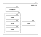
- FIG. 2 is a diagram illustrating an example of a functional configuration of a radio base station according to the present embodiment.
- 5 is a flowchart illustrating an example of a control process of transmission power according to the embodiment.
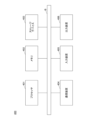
- FIG. 2 is a diagram illustrating an example of a hardware configuration of a computer according to the present embodiment.
- This method is not linked to radio resource control.
- this method has problems such as the possibility of a decrease in communication quality for wireless terminals near cell edges that are far from the wireless base station, and the possibility of the wireless terminal transmission power becoming significantly high depending on the wireless terminal's conditions.
- the radio base station 10 sets the transmission power of the multiple radio terminals 20 so as to suppress the difference in the signal-to-noise ratio (SINR) of the received signals from the multiple radio terminals 20 connected to the radio base station 10 (for example, so as to make them the same value).
- the radio base station 10 also allocates radio resources so as to satisfy the required throughput of all the radio terminals 20. For example, when the radio base station 10 has surplus radio resources, it reduces the transmission power of all the radio terminals 20, and when it has insufficient radio resources, it sets the transmission power of all the radio terminals 20 high.
- the wireless communication system 1 can reduce the transmission power of the wireless terminals while suppressing the disparity in communication quality between the wireless terminals by linking the allocation of wireless resources to the wireless terminals 20 with the control of the transmission power.
- FIG. 2 is a diagram illustrating an example of a functional configuration of a radio base station according to the present embodiment.
- the wireless base station 10 for example, has a computer configuration, and by executing a predetermined program on the computer, realizes a wireless communication unit 201, an acquisition unit 202, a calculation unit 203, a control unit 204, a storage unit 205, etc. Note that at least a part of each of the above functional configurations may be realized by hardware.
- the wireless communication unit 201 executes wireless communication processing to perform predetermined wireless communication with a wireless terminal 20 located within the communication area 11 of the wireless base station 10 using a communication device provided in the wireless base station 10.
- the acquisition unit 202 executes an acquisition process to acquire information on a plurality of wireless terminals 20 (e.g., wireless terminals 20a, 20b, 20c, ... in FIG. 1) that perform wireless communication with the wireless base station 10.
- the information on the plurality of wireless terminals 20 includes, for example, the transmission power of each wireless terminal 20, the SINR (Signal-to-Noise Ratio) of the received signal received by the wireless communication unit 201 from each wireless terminal 20, and the required throughput of each wireless terminal 20.
- the transmission power of each wireless terminal 20 is, for example, the transmission power set by the control unit 204 for the multiple wireless terminals 20.
- the SINR of the received signal is a value that represents the ratio of the power of the desired signal to the power of non-desired signals (interference waves and thermal noise) in the received signal, and is calculated, for example, by the wireless communication unit 201. Note that the SINR is sometimes called the SIR.
- the requested throughput is the throughput (effective data transfer rate at which data is transmitted without errors per unit time) that the wireless terminal 20 requests of the wireless base station 10.
- the calculation unit 203 executes a calculation process to calculate an index indicating the margin of wireless resources based on the information of the multiple wireless terminals 20 acquired by the acquisition unit 202.
- the wireless resources include, for example, a frequency band, a transmission power, or a transmission method.
- the calculation unit 203 obtains the link rate of the wireless terminal 20 from the minimum SINR_m of the SINRs of the signals received from the multiple wireless terminals 20 by using a conversion table stored in advance in the storage unit 205 or the like.
- the calculation unit 203 may input SINR_m into a prediction model or the like that has been machine-learned in advance to predict the link rate of the wireless terminal 20 using the SINR of the wireless terminal 20 as input data, and calculate the link rate of the wireless terminal 20.
- the link rate is the communication speed (maximum throughput) at the current SINR.
- SINR_m is an example of a representative value of the SINRs of the received signals from the multiple wireless terminals 20.
- the representative value of the SINRs of the received signals from the multiple wireless terminals 20 may be, for example, a maximum value, an average value, a median value, or the like.
- the control unit 204 controls the transmission power of the multiple wireless terminals 20 so as to suppress the difference in SINR of the received signals from the multiple wireless terminals 20 and to bring the index calculated by the calculation unit 203 into a predetermined range.
- the control unit 204 uses the difference between the SINR_m of the received signals from the multiple wireless terminals 20 and the SINR of the received signals from each wireless terminal 20 to update the transmission power of each wireless terminal 20 so that the SINR of the received signals from the multiple wireless terminals 20 has the same value.
- the "same value” includes not only the case where all SINR values are completely the same, but also the case where the difference between all SINR values is equal to or less than a predetermined value.
- control unit 204 increases the transmission power of the multiple wireless terminals 20 if the index calculated by the calculation unit 203 exceeds the predetermined range, and decreases the transmission power of the multiple wireless terminals 20 if the index falls below the predetermined range.
- the acquisition unit 202, calculation unit 203, control unit 204, etc. are included in a communication control unit 210 that controls wireless communication by the wireless communication unit 201, for example.
- the storage unit 205 stores various information, data, and programs, including the above-mentioned correspondence table or the learned prediction model, for example, in a storage device provided in the wireless base station 10.
- the wireless communication system 1 may have a base station control device or a relay station that controls multiple wireless base stations 10, and the acquisition unit 202, the calculation unit 203, and some or all of the control unit 204 may be included in the base station control device or the relay station. In short, it is sufficient that the acquisition unit 202, the calculation unit 203, and the control unit 204 described in FIG. 2 are included in the wireless communication system 1.
- This process shows an example of a process executed by the wireless base station 10 (or the wireless communication system 1) including the wireless communication unit 201, the acquisition unit 202, the calculation unit 203, and the control unit 204, etc., as described in FIG.
- step S301 the wireless communication unit 201 receives uplink signals (wireless signals transmitted from multiple wireless terminals 20 to the wireless base station 10).
- the requested throughput is the throughput requested by each wireless terminal 20.
- the acquisition unit 202 acquires the requested throughput value acquired from the wireless terminal 20 from the storage unit 205, the wireless communication unit 201, etc.
- step S305 the calculation unit 203 calculates the total S of the necessary resource ratios R i calculated for each wireless terminal 20.
- step S307 the control unit 204 judges whether "S>1". If “S>1”, the control unit 204 shifts the process to step S307. On the other hand, if "S>1" is not true, the control unit 204 shifts the process to step S308. Note that this process is an example of a process for judging whether the total S of the required resource ratios R i exceeds a predetermined range. Also, “1" is an example of the upper limit of the predetermined range, and other values may be used.
- the control unit 204 increases the transmission power of all wireless terminals 20 by ⁇ dBm.
- ⁇ dbm is a predetermined step size. Through this process, the control unit 204 can increase the transmission power of all wireless terminals 20 when wireless resources are insufficient.
- step S306 the control unit 204 judges whether "S ⁇ 0.97". If “S ⁇ 0.97”, the control unit 204 shifts the process to step S309. On the other hand, if "S ⁇ 0.97” is not true, the control unit 204 shifts the process to step S311.
- this process is an example of a process for determining whether the total S of the required resource ratios R i is below a predetermined range. Also, "0.97" is an example of the lower limit of the predetermined range, and other values may be used.
- step S309 the control unit 204 reduces the transmission power of all wireless terminals 20 by ⁇ dBm. This process allows the control unit 204 to reduce the transmission power of all wireless terminals 20 when there are surplus wireless resources.
- the wireless communication system 1 sets the transmission power of each wireless terminal 20 so as to suppress disparities in communication quality between the wireless terminals 20. Furthermore, after setting the transmission power of each wireless terminal 20, if there are excess wireless resources, the wireless communication system 1 lowers the transmission power of all wireless terminals 20, and if there are insufficient wireless resources, the wireless communication system 1 raises the transmission power of all wireless terminals 20.
- the wireless communication system 1 can reduce the transmission power of the wireless terminals 20 while minimizing the disparity in communication quality between the wireless terminals 20.
- step S307 the process of increasing the transmission power of all wireless terminals 20 may set an upper limit on the transmission power.
- step S309 the process of decreasing the transmission power of all wireless terminals 20 may set a lower limit on the transmission power.
- the computer 400 has a processor 401, a memory 402, a storage device 403, a communication device 404, an input device 405, an output device 406, and a bus B, etc.
- the processor 401 is, for example, an arithmetic device such as a CPU (Central Processing Unit) that realizes various functions by executing a specific program.
- the memory 402 is a storage medium readable by the computer 400, and includes, for example, a RAM (Random Access Memory) and a ROM (Read Only Memory).
- the storage device 403 is a computer-readable storage medium, and may include, for example, a HDD (Hard Disk Drive), an SSD (Solid State Drive), various optical disks, and magneto-optical disks.
- the communication device 404 includes one or more pieces of hardware (transmitting/receiving devices) for communicating with other devices via a wireless or wired network.
- the communication device 404 may include, for example, an antenna, a radio circuit, and a processor for communication that executes baseband processing and communication control processing.
- the bus B is commonly connected to each of the above components and transmits, for example, address signals, data signals, and various control signals.
- the processor 401 is not limited to a CPU, and may be, for example, a DSP (Digital Signal Processor), a PLD (Programmable Logic Device), or an FPGA (Field Programmable Gate Array).
- the wireless base station 10 and the wireless terminal 20 in this embodiment are not limited to being realized by dedicated devices, but may be realized by a general-purpose computer.
- a program for realizing this function may be recorded on a computer-readable recording medium, and the program recorded on the recording medium may be read into a computer system and executed to realize the function.
- the "computer system” here includes hardware such as an OS and peripheral devices.
- “computer-readable recording media” includes various storage devices such as portable media such as flexible disks, optical magnetic disks, ROMs, and CD-ROMs, as well as hard disks built into computer systems. Furthermore, “computer-readable recording media” may also include devices that dynamically hold a program for a short period of time, such as a communication line when transmitting a program via a network such as the Internet or a communication line such as a telephone line, and devices that hold a program for a certain period of time, such as volatile memory inside a computer system that serves as a server or client in such cases.
- the above program may be for realizing some of the functions described above, or may be capable of realizing the functions described above in combination with a program already recorded in the computer system, or may be realized using hardware such as a PLD (Programmable Logic Device) or FPGA (Field Programmable Gate Array).
- PLD Programmable Logic Device
- FPGA Field Programmable Gate Array
- the wireless communication system 1 sets the transmission power of the multiple wireless terminals 20 so as to suppress the difference in SINR of the received signals from the multiple wireless terminals 20 that communicate wirelessly with the wireless base station 10 (so that the SINR is uniform).
- the wireless communication system 1 eliminates (or reduces) the difference in SINR between the wireless terminals 20, and can prevent degradation of communication quality due to retransmission, or increase in delay time, from becoming significant for a specific wireless terminal 20.
- the wireless communication system 1 can avoid excess radio resources and efficiently control the transmission power of the wireless terminal 20 in response to communication requests.
- This specification discloses at least the following wireless base station, wireless communication system, and wireless communication method.
- (Section 1) an acquisition unit that acquires information on a plurality of wireless terminals that perform wireless communication with a wireless base station, the information including transmission powers of the plurality of wireless terminals, SINRs of signals received from the plurality of wireless terminals, and required throughputs of the plurality of wireless terminals; a calculation unit that calculates an index indicating a margin of radio resources based on information of the plurality of radio terminals; a control unit that controls transmission power of the plurality of wireless terminals so as to suppress a difference between SINRs of received signals from the plurality of wireless terminals and to make the index fall within a predetermined range;
- a wireless base station having the above configuration.
- the calculation unit calculates a ratio of radio resources required for each of the wireless terminals based on SINRs of received signals from the wireless terminals and required throughputs of the wireless terminals; a sum of the ratios of the radio resources required for each of the radio terminals to calculate the index;
- the radio base station according to claim 1. the calculation unit calculates a link rate of the wireless terminal from a representative value of SINRs of received signals from the plurality of wireless terminals; 3.
- the radio base station according to claim 2 wherein a ratio of a required throughput of each radio terminal to the link rate is set as a ratio of radio resources required for each radio terminal.
- the control unit is using a difference between a representative value of the SINRs of the received signals from the plurality of wireless terminals and the SINRs of the received signals from each of the wireless terminals, so that the SINRs of the received signals from the plurality of wireless terminals are the same value, and then setting the transmission power of each of the wireless terminals; If the indicator exceeds the predetermined range, increasing the transmission power of the plurality of wireless terminals by a predetermined value; If the indicator falls below the predetermined range, reducing the transmission power of the plurality of wireless terminals by a predetermined value. 4.
- the wireless base station according to claim 1.
- a wireless communication system including a wireless base station, an acquisition unit that acquires information on a plurality of wireless terminals that wirelessly communicate with the wireless base station, the information including transmission powers of the plurality of wireless terminals, SINRs of received signals from the plurality of wireless terminals, and required throughputs of the plurality of wireless terminals; a calculation unit that calculates an index indicating a margin of radio resources based on information of the plurality of radio terminals; a control unit that controls transmission power of the plurality of wireless terminals so as to suppress a difference between SINRs of received signals from the plurality of wireless terminals and to make the index fall within a predetermined range;
- a wireless communication system comprising: (Section 6) In a wireless communication system including a wireless base station, The computer A process of acquiring information on a plurality of wireless terminals that perform wireless communication with the wireless base station, the information including transmission powers of the plurality of wireless terminals, SINRs of received signals from the plurality of wireless terminals, and required throughputs of
Landscapes
- Engineering & Computer Science (AREA)
- Computer Networks & Wireless Communication (AREA)
- Signal Processing (AREA)
- Mobile Radio Communication Systems (AREA)
Abstract
無線端末間の通信品質の格差を抑制しつつ、無線端末の送信電力を低減するために、無線基地局は、無線基地局と無線通信を行う複数の無線端末の送信電力と、前記複数の無線端末からの受信信号のSINRと、前記複数の無線端末の要求スループットと、を含む前記複数の無線端末の情報を取得する取得部と、前記複数の無線端末の情報に基づいて、無線リソースの余裕度を示す指標を算出する算出部と、前記複数の無線端末からの受信信号のSINRの差を抑制し、かつ前記指標が所定の範囲内となるように、前記複数の無線端末の送信電力を制御する制御部と、を有する。
Description
本発明は、無線基地局、無線通信システム、及び無線通信方法に関する。
無線端末の位置(無線基地局からの距離)ごとに異なる送信電力で送信させることで、容量を拡大しつつ隣接セル干渉を抑制する技術が知られている(例えば、非特許文献1参照)。
"さらなるビットコストの低減に向けたSuper 3Gの開発"、NTT DoCoMoテクニカルジャーナル(VOL.16 NO.2)、[平成4年5月28日検索]、<URL: https://www.docomo.ne.jp/binary/pdf/corporate/technology/rd/technical_journal/bn/vol16_2/vol16_2_008jp.pdf>
しかし、この方法では、無線リソースの割当と、無線端末での電力制御方法とが連動していないため、例えば、セルエッジ付近の無線端末の通信品質が低下する、無線端末の状況によって無線端末の送信電力が著しく高くなることがある等の問題がある。
本発明の実施形態は、上記の問題点に鑑みてなされたものであって、無線端末間の通信品質の格差を抑制しつつ、無線端末の送信電力を低減する無線通信システムを提供する。
上記の課題を解決するため、本発明の実施形態に係る無線基地局は、無線基地局と無線通信を行う複数の無線端末の送信電力と、前記複数の無線端末からの受信信号のSINRと、前記複数の無線端末の要求スループットと、を含む前記複数の無線端末の情報を取得する取得部と、前記複数の無線端末の情報に基づいて、無線リソースの余裕度を示す指標を算出する算出部と、前記複数の無線端末からの受信信号のSINRの差を抑制し、かつ前記指標が所定の範囲内となるように、前記複数の無線端末の送信電力を制御する制御部と、を有する。
本発明の実施形態によれば、無線端末間の通信品質の格差を抑制しつつ、無線端末の送信電力を低減する無線通信システムを提供することができる。
以下、図面を参照して本発明の実施の形態(本実施形態)を説明する。以下で説明する実施形態は一例に過ぎず、本発明が適用される実施形態は、以下の実施形態に限られない。
<システム構成>
図1は、本実施形態に係る無線通信システムのシステム構成の例を示す図である。無線通信システム1は、無線基地局10と、無線基地局10と無線通信を行う複数の無線端末20a、20b、20c、・・・とを含む。無線通信システム1の無線通信方式は、例えば、5G(5th. Generation)、LTE(Long Term Evolution)、無線LAN(Local Area Network)等の様々な無線通信方式であってよい。
図1は、本実施形態に係る無線通信システムのシステム構成の例を示す図である。無線通信システム1は、無線基地局10と、無線基地局10と無線通信を行う複数の無線端末20a、20b、20c、・・・とを含む。無線通信システム1の無線通信方式は、例えば、5G(5th. Generation)、LTE(Long Term Evolution)、無線LAN(Local Area Network)等の様々な無線通信方式であってよい。
なお、以下の説明において、複数の無線端末20a、20b、20c、・・・のうち、任意の無線端末を示す場合、「無線端末20」を用いる。また、図1に示した無線基地局10、及び無線端末20の数は一例であり、無線通信システム1には、さらに多くの無線基地局10、及び無線端末20が含まれる。
無線基地局10は、無線基地局10の通信エリア11内にある無線端末20と無線通信が可能な基地局である。無線端末20は、無線基地局10の通信エリア11内において、無線基地局10と無線通信が可能な無線局である。
(処理の概要)
例えば、非特許文献1に示されるような従来の技術では、無線端末の位置(無線基地局からの距離)ごとに異なる送信電力で送信させることで、容量を拡大しつつ隣接セル干渉を抑制している。
例えば、非特許文献1に示されるような従来の技術では、無線端末の位置(無線基地局からの距離)ごとに異なる送信電力で送信させることで、容量を拡大しつつ隣接セル干渉を抑制している。
この方法は、無線リソース制御とは連動していない。また、この方法では、無線基地局から距離が離れたセルエッジ付近の無線端末の通信品質が低下する可能性がある、無線端末の状況によって無線端末送信電力が著しく高くなることがある等の問題がある。
そこで、本実施形態に係る無線基地局10は、上り送信電力(無線端末20の送信電力)の制御と、無線リソースの割り当てとを連動させて、無線端末間の通信品質の格差を抑制しつつ、無線端末の送信電力を低減する機能を有している。
例えば、無線基地局10は、無線基地局10に接続する複数の無線端末20からの受信信号のSINR(Signal-to-Noise Ratio)の差を抑制するように(例えば、同じ値となるように)、複数の無線端末20の送信電力を設定する。また、無線基地局10は、全ての無線端末20の要求スループットを満たすように、無線リソースを割り当てる。例えば、無線基地局10は、無線基地局10の無線リソースが余る場合、全ての無線端末20の送信電力を低下させ、無線リソースが不足する場合、全ての無線端末20の送信電力を高く設定する。
この手法により、無線通信システム1は、無線端末20の無線リソースの割り当てと送信電力の制御とを連動させて、無線端末間の通信品質の格差を抑制しつつ、無線端末の送信電力を低減することができる。
<機能構成>
図2は、本実施形態に係る無線基地局の機能構成の例を示す図である。
図2は、本実施形態に係る無線基地局の機能構成の例を示す図である。
無線基地局10は、例えば、コンピュータの構成を備え、当該コンピュータで所定のプログラムを実行することにより、無線通信部201、取得部202、算出部203、制御部204、及び記憶部205等を実現している。なお、上記の各機能構成のうち、少なくとも一部は、ハードウェアによって実現されるものであってもよい。
無線通信部201は、無線基地局10が備える通信装置を用いて、無線基地局10の通信エリア11内にある無線端末20と所定の無線通信を行う無線通信処理を実行する。
取得部202は、無線基地局10と無線通信を行う複数の無線端末20(例えば、図1の無線端末20a、20b、20c、・・・)の情報を取得する取得処理を実行する。ここで、複数の無線端末20の情報には、例えば、各無線端末20の送信電力、無線通信部201が各無線端末20から受信した受信信号のSINR(Signal-to-Noise Ratio)、及び各無線端末20の要求スループット等が含まれる。
各無線端末20の送信電力は、例えば、制御部204は、複数の無線端末20に設定した送信電力である。受信信号のSINRは、受信信号のうち、所望信号の電力と所望信号以外(干渉波、及び熱雑音)の電力の比を表す値であり、例えば、無線通信部201が算出する。なお、SINRは、SIRと呼ばれる場合がある。要求スループットは、無線端末20が無線基地局10に要求しているスループット(単位時間当りに、誤りなく伝送される実効的なデータ転送速度)である。
算出部203は、取得部202が取得した複数の無線端末20の情報に基づいて、無線リソースの余裕度を示す指標を算出する算出処理を実行する。無線リソースには、例えば、周波数帯域、送信電力、又は伝送方式等が含まれる。
例えば、算出部203は、複数の無線端末20からの受信信号のSINRの最小値SINR_mから、予め記憶部205等に記憶した変換表を用いて、無線端末20のリンクレートを求める。或いは、算出部203は、無線端末20のSINRを入力データとして、無線端末20のリンクレートを予測するように予め機械学習した予測モデル等に、SINR_mを入力して、無線端末20のリンクレートを算出してもよい。ここで、リンクレートは、現在のSINRにおける通信可能速度(最大スループット)である。
また、SINR_mは、複数の無線端末20からの受信信号のSINRの代表値の一例である。複数の無線端末20からの受信信号のSINRの代表値は、例えば、最大値、平均値、又は中央値等であってもよい。
また、SINR_mは、複数の無線端末20からの受信信号のSINRの代表値の一例である。複数の無線端末20からの受信信号のSINRの代表値は、例えば、最大値、平均値、又は中央値等であってもよい。
また、算出部203は、算出した無線端末20のリンクレートと、各無線端末20の要求スループットとから、無線端末20ごとに必要な無線リソースの割合Ri(=要求スループット/リンクレート)を算出する。さらに、算出部203は、複数の無線端末20の無線リソースの割合Riの合計値S(以下、リソース割合の合計値Sとよぶ)を算出する。なお、リソース割合Riの合計値Sは、無線リソースの余裕度を示す指標の一例である。
制御部204は、複数の無線端末20からの受信信号のSINRの差を抑制し、かつ算出部203が算出した指標が所定の範囲内となるように、複数の無線端末の送信電力を制御する。例えば、制御部204は、複数の無線端末20からの受信信号のSINR_mと、各無線端末20からの受信信号のSINRとの差分を用いて、複数の無線端末20からの受信信号のSINRが同じ値になるように、各無線端末20の送信電力を更新する。ここで、「同じ値」には、全てのSINRの値が完全に一致する場合だけではなく、全てのSINRの値の差が、所定値以下となる場合が含まれる。また、制御部204は、各無線端末20の送信電力を更新した後に、算出部203が算出した指標が所定の範囲を上回る場合、複数の無線端末20の送信電力を上げて、指標が所定の範囲を下回る場合、複数の無線端末20の送信電力を下げる。
なお、取得部202、算出部203、及び制御部204等は、例えば、無線通信部201による無線通信を制御する通信制御部210に含まれる。
記憶部205は、例えば、無線基地局10が備えるストレージデバイス等に、上述した対応表、又は学習済の予測モデル等を含む様々な情報、データ、及びプログラム等を記憶する。
なお、図2に示した無線基地局10の機能構成は一例である。例えば、無線通信システム1は、複数の無線基地局10を制御する基地局制御装置、又は中継局等を有し、取得部202、算出部203、及び制御部204の一部、又は全部は、基地局制御装置、又は中継局等が有していてもよい。要するに、図2で説明した取得部202、算出部203、及び制御部204は、無線通信システム1が有していればよい。
<処理の流れ>
続いて、本実施形態に係る無線通信方法の処理の流れについて説明する。この処理は、図2で説明した、無線通信部201、取得部202、算出部203、及び制御部204等を有する無線基地局10(又は無線通信システム1)が実行する処理の一例を示している。
続いて、本実施形態に係る無線通信方法の処理の流れについて説明する。この処理は、図2で説明した、無線通信部201、取得部202、算出部203、及び制御部204等を有する無線基地局10(又は無線通信システム1)が実行する処理の一例を示している。
ステップS301において、無線通信部201は、上り信号(複数の無線端末20が無線基地局10に送信する無線信号)を受信する。
ステップS302において、取得部202は、各無線端末20の送信電力、受信電力のSINR、及び要求スループット等を含む複数の無線端末20の情報を取得する。ここで、各無線端末20の送信電力は、制御部204が、無線基地局10と無線通信を行う複数の無線端末20に設定した送信電力である。なお、取得部202は、無線端末20が送信した上り信号から、無線端末20の送信電力の情報を取得するもの等であってもよい。
受信電力のSINRは、無線通信部201が、複数の無線端末20から受信した受信信号のSINRである。取得部202は、複数の無線端末20から受信した受信信号のSINRの値を、例えば、無線通信部201から取得する。或いは、取得部202は、無線通信部201から、複数の無線端末20から受信した受信電力の値を取得し、取得した値を用いて受信信号のSINRを算出してもよい。
要求スループットは、各無線端末20が要求するスループットである。取得部202は、例えば、無線通信部201が、無線端末20と無線通信を開始するとき等に、無線端末20から取得した要求するスループットの値を、記憶部205、又は無線通信部201等から取得する。
ステップS303において、制御部204は、複数の無線端末20のSINRの最低値SINR_mと、各無線端末20のSINR_iとの差分di(=SINR_i―SINR_m)を算出する。また、制御部204は、各無線端末20の送信電力PiをPi'(=Pi-di)に設定する。なお、この処理は、制御部204が、SINR_mと、SINR_iとの差分を用いて、複数の無線端末20からの受信信号のSINRの差を抑制するように、各無線端末20の送信電力を更新する処理の一例である。この処理により、複数の無線端末20のSINRの値が、同じ値に設定される。
ステップS304において、算出部203は、SINR_mから、無線端末20の必要なリソース割合Riを算出する。例えば、算出部203は、前述したように、予め記憶部205に記憶した変換表、又は学習済の予測モデル等を用いて、SINR_mから、リンクレートを算出する。また、算出部203は、算出したリンクレートを用いて、無線端末20ごとに、必要なリソース割合Ri(=要求スループット/リンクレート)を算出する。
ステップS305において、算出部203は、無線端末20ごとに算出した、必要なリソース割合Riの合計Sを算出する。
ステップS307において、制御部204は、「S>1」であるかを判断する。「S>1」である場合、制御部204は、処理をステップS307に移行させる。一方、「S>1」でない場合、制御部204は、処理をステップS308に移行させる。なお、この処理は、必要なリソース割合Riの合計Sが、所定の範囲を上回っているかを判断する処理の一例である。また、「1」は、所定の範囲の上限の一例であり、他の値であってもよい。
ステップS307に移行すると、制御部204は、全ての無線端末20の送信電力をΔdBmずつ上げる。ここで、Δdbmは、予め定められたステップ幅である。この処理により、制御部204は、無線リソースが不足する場合、全ての無線端末20の送信電力を上げることができる。
一方、ステップS306からS308に移行すると、制御部204は、「S<0.97」であるかを判断する。「S<0.97」である場合、制御部204は、処理をステップS309に移行させる。一方、「S<0.97」でない場合、制御部204は、処理をステップS311に移行させる。なお、この処理は、必要なリソース割合Riの合計Sが、所定の範囲を下回っているかを判断する処理の一例である。また、「0.97」は、所定の範囲の下限の一例であり、他の値であってもよい。
ステップS309に移行すると、制御部204は、全ての無線端末20の送信電力をΔdBmずつ下げる。この処理により、制御部204は、無線リソースが余る場合、全ての無線端末20の送信電力を下げることができる。
ステップS307、S309から、S310に移行すると、制御部204は、SINR_mを更新して、処理をステップS304に戻す。例えば、Sが所定の範囲より大きい場合、SINR_m=SINR_m-Δとし、Sが所定の範囲より小さい場合、SINR_m=SINR_m+Δとする。
一方、ステップS308からS311に移行すると、制御部204は、必要なリソース割合Riの合計Sが所定の範囲(0.97≦S≦1)内であると判断し、ステップS312の処理を実行する。ステップS312において、制御部204は、ステップS301~S311で決定した送信電力を、各無線端末20に通知(設定)する。
図3の処理により、無線通信システム1は、無線端末20間の通信品質の格差を抑制するように、各無線端末20の送信電力を設定する。また、無線通信システム1は、各無線端末20の送信電力を設定した後に、無線リソースが余る場合、全ての無線端末20の送信電力を下げ、無線リソースが不足する場合、全ての無線端末20の送信電力を上げる。
これにより、無線通信システム1は、無線端末20間の通信品質の格差を抑制しつつ、無線端末20の送信電力を低減することができる。
なお、図3に示した処理は一例である。例えば、ステップS307において、全ての無線端末20の送信電力を上げる処理には、送信電力の上限値を設けてもよい。同様に、ステップS309において、全ての無線端末20の送信電力を下げる処理には、送信電力の下限値を設けてもよい。
<ハードウェア構成>
図4は、本実施形態に係るコンピュータのハードウェア構成の例を示す図である。無線基地局10、及び無線端末20は、例えば、図4に示すようなコンピュータ400のハードウェア構成を備えている。また、無線通信システム1に、複数の無線基地局10を制御する基地局制御装置が含まれる場合、基地局制御装置もコンピュータ400のハードウェア構成を備えている。
図4は、本実施形態に係るコンピュータのハードウェア構成の例を示す図である。無線基地局10、及び無線端末20は、例えば、図4に示すようなコンピュータ400のハードウェア構成を備えている。また、無線通信システム1に、複数の無線基地局10を制御する基地局制御装置が含まれる場合、基地局制御装置もコンピュータ400のハードウェア構成を備えている。
図4の例では、コンピュータ400は、プロセッサ401、メモリ402、ストレージデバイス403、通信装置404、入力装置405、出力装置406、及びバスB等を有する。
プロセッサ401は、例えば、所定のプログラムを実行することにより、様々な機能を実現するCPU(Central Processing Unit)等の演算装置である。メモリ402は、コンピュータ400が読み取り可能な記憶媒体であり、例えば、RAM(Random Access Memory)、ROM(Read Only Memory)等を含む。ストレージデバイス403は、コンピュータ読み取り可能な記憶媒体であり、例えば、HDD(Hard Disk Drive)、SSD(Solid State Drive)、各種の光ディスク、及び光磁気ディスク等を含み得る。
通信装置404は、無線、又は有線のネットワークを介して他の装置と通信を行うための1つ以上のハードウェア(送受信デバイス)を含む。通信装置404には、例えば、アンテナ、無線回路、及びベースバンド処理と通信制御処理とを実行する通信用のプロセッサ等が含まれ得る。
入力装置405は、外部からの入力を受け付ける入力デバイス(例えば、キーボード、マウス、マイクロフォン、スイッチ、ボタン、センサ等)である。出力装置406は、外部への出力を実施する出力デバイス(例えば、ディスプレイ、スピーカ、LEDランプ等)である。なお、入力装置405と出力装置406とは、一体となった構成(例えば、タッチパネルディスプレイ等の入出力装置)であってもよい。
バスBは、上記の各構成要素に共通に接続され、例えば、アドレス信号、データ信号、及び各種の制御信号等を伝送する。なお、プロセッサ401は、CPUに限られず、例えば、DSP(Digital Signal Processor)、PLD(Programmable Logic Device)、又はFPGA(Field Programmable Gate Array)等であってもよい。
(補足)
なお、本実施形態における無線基地局10、及び無線端末20は専用装置による実現に限らず、汎用コンピュータで実現するようにしてもよい。その場合、この機能を実現するためのプログラムをコンピュータ読み取り可能な記録媒体に記録して、この記録媒体に記録されたプログラムをコンピュータシステムに読み込ませ、実行することによって実現してもよい。なお、ここでいう「コンピュータシステム」とは、OSや周辺機器等のハードウェアを含むものとする。
なお、本実施形態における無線基地局10、及び無線端末20は専用装置による実現に限らず、汎用コンピュータで実現するようにしてもよい。その場合、この機能を実現するためのプログラムをコンピュータ読み取り可能な記録媒体に記録して、この記録媒体に記録されたプログラムをコンピュータシステムに読み込ませ、実行することによって実現してもよい。なお、ここでいう「コンピュータシステム」とは、OSや周辺機器等のハードウェアを含むものとする。
また、「コンピュータ読み取り可能な記録媒体」とは、フレキシブルディスク、光磁気ディスク、ROM、CD-ROM等の可搬媒体、コンピュータシステムに内蔵されるハードディスク等の様々な記憶装置を含む。さらに「コンピュータ読み取り可能な記録媒体」とは、インターネット等のネットワークや電話回線等の通信回線を介してプログラムを送信する場合の通信線のように、短時間の間、動的にプログラムを保持するもの、その場合のサーバやクライアントとなるコンピュータシステム内部の揮発性メモリのように、一定時間プログラムを保持しているものも含んでもよい。
また上記プログラムは、前述した機能の一部を実現するためのものであっても良く、さらに前述した機能をコンピュータシステムにすでに記録されているプログラムとの組み合わせで実現できるものであっても良く、PLD(Programmable Logic Device)やFPGA(Field Programmable Gate Array)等のハードウェアを用いて実現されるものであってもよい。
<実施形態の効果>
本実施形態によれば、無線端末20間の通信品質の格差を抑制しつつ、無線端末20の送信電力を低減する無線通信システム1を提供することができる。
本実施形態によれば、無線端末20間の通信品質の格差を抑制しつつ、無線端末20の送信電力を低減する無線通信システム1を提供することができる。
例えば、無線通信システム1は、無線基地局10と無線通信を行う複数の無線端末20からの受信信号のSINRの差を抑制するように(SINRが一律となるように)、複数の無線端末20の送信電力を設定する。これにより、無線通信システム1は、無線端末20間でSINRの格差がなくなる(又は減少する)ため、再送などによる通信品質の低下、又は遅延時間の増大等が、特定の無線端末20で著しくなることを回避することができる。
また、無線通信システム1は、無線リソースの制御と、送信電力の制御とを連動させることにより、無線リソースの余りを回避し、通信要求に応じて効率的に無線端末20の送信電力を制御することができる。
<実施形態のまとめ>
本明細書には、少なくとも下記の各項の無線基地局、無線通信システム、及び無線通信方法が開示されている。
(第1項)
無線基地局と無線通信を行う複数の無線端末の送信電力と、前記複数の無線端末からの受信信号のSINRと、前記複数の無線端末の要求スループットと、を含む前記複数の無線端末の情報を取得する取得部と、
前記複数の無線端末の情報に基づいて、無線リソースの余裕度を示す指標を算出する算出部と、
前記複数の無線端末からの受信信号のSINRの差を抑制し、かつ前記指標が所定の範囲内となるように、前記複数の無線端末の送信電力を制御する制御部と、
を有する、無線基地局。
(第2項)
前記算出部は、前記複数の無線端末からの受信信号のSINRと、前記複数の無線端末の要求スループットに基づいて、前記無線端末ごとに必要な無線リソースの割合を算出し、
前記無線端末ごとに必要な無線リソースの割合を合計して前記指標を算出する、
請求項1に記載の無線基地局。
(第3項)
前記算出部は、前記複数の無線端末からの受信信号のSINRの代表値から、前記無線端末のリンクレートを求め、
前記リンクレートに対する各無線端末の要求スループットの割合を、各無線端末に必要な無線リソースの割合とする、第2項に記載の無線基地局。
(第4項)
前記制御部は、
前記複数の無線端末からの受信信号のSINRの代表値と、各無線端末からの受信信号のSINRとの差分を用いて、前記複数の無線端末からの受信信号のSINRが同じ値となるように、各無線端末の送信電力を設定した後に、
前記指標が前記所定の範囲を上回る場合、前記複数の無線端末の送信電力を所定の値ずつ上げて、
前記指標が前記所定の範囲を下回る場合、前記複数の無線端末の送信電力を所定の値ずつ下げる、
第1項~第3項のいずれかに記載の無線基地局。
(第5項)
無線基地局を含む無線通信システムであって、
前記無線基地局と無線通信を行う複数の無線端末の送信電力と、前記複数の無線端末からの受信信号のSINRと、前記複数の無線端末の要求スループットと、を含む前記複数の無線端末の情報を取得する取得部と、
前記複数の無線端末の情報に基づいて、無線リソースの余裕度を示す指標を算出する算出部と、
前記複数の無線端末からの受信信号のSINRの差を抑制し、かつ前記指標が所定の範囲内となるように、前記複数の無線端末の送信電力を制御する制御部と、
を有する、無線通信システム。
(第6項)
無線基地局を含む無線通信システムにおいて、
コンピュータが、
前記無線基地局と無線通信を行う複数の無線端末の送信電力と、前記複数の無線端末からの受信信号のSINRと、前記複数の無線端末の要求スループットと、を含む前記複数の無線端末の情報を取得する処理と、
前記複数の無線端末の情報に基づいて、無線リソースの余裕度を示す指標を算出する処理と、
前記複数の無線端末からの受信信号のSINRの差を抑制し、かつ前記指標が所定の範囲内となるように、前記複数の無線端末の送信電力を制御する処理と、
を実行する、無線通信方法。
(第7項)
無線基地局を含む無線通信システムにおいて、
コンピュータに、
前記無線基地局と無線通信を行う複数の無線端末の送信電力と、前記複数の無線端末からの受信信号のSINRと、前記複数の無線端末の要求スループットと、を含む前記複数の無線端末の情報を取得する処理と、
前記複数の無線端末の情報に基づいて、無線リソースの余裕度を示す指標を算出する処理と、
前記複数の無線端末からの受信信号のSINRの差を抑制し、かつ前記指標が所定の範囲内となるように、前記複数の無線端末の送信電力を制御する処理と、
を実行させる、プログラムを記憶した記憶媒体。
本明細書には、少なくとも下記の各項の無線基地局、無線通信システム、及び無線通信方法が開示されている。
(第1項)
無線基地局と無線通信を行う複数の無線端末の送信電力と、前記複数の無線端末からの受信信号のSINRと、前記複数の無線端末の要求スループットと、を含む前記複数の無線端末の情報を取得する取得部と、
前記複数の無線端末の情報に基づいて、無線リソースの余裕度を示す指標を算出する算出部と、
前記複数の無線端末からの受信信号のSINRの差を抑制し、かつ前記指標が所定の範囲内となるように、前記複数の無線端末の送信電力を制御する制御部と、
を有する、無線基地局。
(第2項)
前記算出部は、前記複数の無線端末からの受信信号のSINRと、前記複数の無線端末の要求スループットに基づいて、前記無線端末ごとに必要な無線リソースの割合を算出し、
前記無線端末ごとに必要な無線リソースの割合を合計して前記指標を算出する、
請求項1に記載の無線基地局。
(第3項)
前記算出部は、前記複数の無線端末からの受信信号のSINRの代表値から、前記無線端末のリンクレートを求め、
前記リンクレートに対する各無線端末の要求スループットの割合を、各無線端末に必要な無線リソースの割合とする、第2項に記載の無線基地局。
(第4項)
前記制御部は、
前記複数の無線端末からの受信信号のSINRの代表値と、各無線端末からの受信信号のSINRとの差分を用いて、前記複数の無線端末からの受信信号のSINRが同じ値となるように、各無線端末の送信電力を設定した後に、
前記指標が前記所定の範囲を上回る場合、前記複数の無線端末の送信電力を所定の値ずつ上げて、
前記指標が前記所定の範囲を下回る場合、前記複数の無線端末の送信電力を所定の値ずつ下げる、
第1項~第3項のいずれかに記載の無線基地局。
(第5項)
無線基地局を含む無線通信システムであって、
前記無線基地局と無線通信を行う複数の無線端末の送信電力と、前記複数の無線端末からの受信信号のSINRと、前記複数の無線端末の要求スループットと、を含む前記複数の無線端末の情報を取得する取得部と、
前記複数の無線端末の情報に基づいて、無線リソースの余裕度を示す指標を算出する算出部と、
前記複数の無線端末からの受信信号のSINRの差を抑制し、かつ前記指標が所定の範囲内となるように、前記複数の無線端末の送信電力を制御する制御部と、
を有する、無線通信システム。
(第6項)
無線基地局を含む無線通信システムにおいて、
コンピュータが、
前記無線基地局と無線通信を行う複数の無線端末の送信電力と、前記複数の無線端末からの受信信号のSINRと、前記複数の無線端末の要求スループットと、を含む前記複数の無線端末の情報を取得する処理と、
前記複数の無線端末の情報に基づいて、無線リソースの余裕度を示す指標を算出する処理と、
前記複数の無線端末からの受信信号のSINRの差を抑制し、かつ前記指標が所定の範囲内となるように、前記複数の無線端末の送信電力を制御する処理と、
を実行する、無線通信方法。
(第7項)
無線基地局を含む無線通信システムにおいて、
コンピュータに、
前記無線基地局と無線通信を行う複数の無線端末の送信電力と、前記複数の無線端末からの受信信号のSINRと、前記複数の無線端末の要求スループットと、を含む前記複数の無線端末の情報を取得する処理と、
前記複数の無線端末の情報に基づいて、無線リソースの余裕度を示す指標を算出する処理と、
前記複数の無線端末からの受信信号のSINRの差を抑制し、かつ前記指標が所定の範囲内となるように、前記複数の無線端末の送信電力を制御する処理と、
を実行させる、プログラムを記憶した記憶媒体。
以上、本実施形態について説明したが、本発明はかかる特定の実施形態に限定されるものではなく、特許請求の範囲に記載された本発明の要旨の範囲内において、種々の変形・変更が可能である。
1 無線通信システム
10 無線基地局
20、20a、20b、20c 無線端末
202 取得部
203 算出部
204 制御部
205 記憶部
400 コンピュータ
10 無線基地局
20、20a、20b、20c 無線端末
202 取得部
203 算出部
204 制御部
205 記憶部
400 コンピュータ
Claims (6)
- 無線基地局と無線通信を行う複数の無線端末の送信電力と、前記複数の無線端末からの受信信号のSINRと、前記複数の無線端末の要求スループットと、を含む前記複数の無線端末の情報を取得する取得部と、
前記複数の無線端末の情報に基づいて、無線リソースの余裕度を示す指標を算出する算出部と、
前記複数の無線端末からの受信信号のSINRの差を抑制し、かつ前記指標が所定の範囲内となるように、前記複数の無線端末の送信電力を制御する制御部と、
を有する、無線基地局。 - 前記算出部は、前記複数の無線端末からの受信信号のSINRと、前記複数の無線端末の要求スループットに基づいて、前記無線端末ごとに必要な無線リソースの割合を算出し、
前記無線端末ごとに必要な無線リソースの割合を合計して前記指標を算出する、
請求項1に記載の無線基地局。 - 前記算出部は、前記複数の無線端末からの受信信号のSINRの代表値から、前記無線端末のリンクレートを求め、
前記リンクレートに対する各無線端末の要求スループットの割合を、各無線端末に必要な無線リソースの割合とする、請求項2に記載の無線基地局。 - 前記制御部は、
前記複数の無線端末からの受信信号のSINRの代表値と、各無線端末からの受信信号のSINRとの差分を用いて、前記複数の無線端末からの受信信号のSINRが同じ値となるように、各無線端末の送信電力を設定した後に、
前記指標が前記所定の範囲を上回る場合、前記複数の無線端末の送信電力を所定の値ずつ上げて、
前記指標が前記所定の範囲を下回る場合、前記複数の無線端末の送信電力を所定の値ずつ下げる、
請求項1乃至3のいずれか一項に記載の無線基地局。 - 無線基地局を含む無線通信システムであって、
前記無線基地局と無線通信を行う複数の無線端末の送信電力と、前記複数の無線端末からの受信信号のSINRと、前記複数の無線端末の要求スループットと、を含む前記複数の無線端末の情報を取得する取得部と、
前記複数の無線端末の情報に基づいて、無線リソースの余裕度を示す指標を算出する算出部と、
前記複数の無線端末からの受信信号のSINRの差を抑制し、かつ前記指標が所定の範囲内となるように、前記複数の無線端末の送信電力を制御する制御部と、
を有する、無線通信システム。 - 無線基地局を含む無線通信システムにおいて、
コンピュータが、
前記無線基地局と無線通信を行う複数の無線端末の送信電力と、前記複数の無線端末からの受信信号のSINRと、前記複数の無線端末の要求スループットと、を含む前記複数の無線端末の情報を取得する処理と、
前記複数の無線端末の情報に基づいて、無線リソースの余裕度を示す指標を算出する処理と、
前記複数の無線端末からの受信信号のSINRの差を抑制し、かつ前記指標が所定の範囲内となるように、前記複数の無線端末の送信電力を制御する処理と、
を実行する、無線通信方法。
Priority Applications (2)
| Application Number | Priority Date | Filing Date | Title |
|---|---|---|---|
| JP2025525885A JPWO2024252640A1 (ja) | 2023-06-08 | 2023-06-08 | |
| PCT/JP2023/021428 WO2024252640A1 (ja) | 2023-06-08 | 2023-06-08 | 無線基地局、無線通信システム、及び無線通信方法 |
Applications Claiming Priority (1)
| Application Number | Priority Date | Filing Date | Title |
|---|---|---|---|
| PCT/JP2023/021428 WO2024252640A1 (ja) | 2023-06-08 | 2023-06-08 | 無線基地局、無線通信システム、及び無線通信方法 |
Publications (1)
| Publication Number | Publication Date |
|---|---|
| WO2024252640A1 true WO2024252640A1 (ja) | 2024-12-12 |
Family
ID=93795700
Family Applications (1)
| Application Number | Title | Priority Date | Filing Date |
|---|---|---|---|
| PCT/JP2023/021428 Ceased WO2024252640A1 (ja) | 2023-06-08 | 2023-06-08 | 無線基地局、無線通信システム、及び無線通信方法 |
Country Status (2)
| Country | Link |
|---|---|
| JP (1) | JPWO2024252640A1 (ja) |
| WO (1) | WO2024252640A1 (ja) |
Citations (2)
| Publication number | Priority date | Publication date | Assignee | Title |
|---|---|---|---|---|
| JPH10108249A (ja) * | 1996-09-26 | 1998-04-24 | Nippon Telegr & Teleph Corp <Ntt> | 送信電力制御方式及び送信電力制御方法 |
| WO2012005154A1 (ja) * | 2010-07-07 | 2012-01-12 | 株式会社 エヌ・ティ・ティ・ドコモ | 基地局装置及び方法 |
-
2023
- 2023-06-08 WO PCT/JP2023/021428 patent/WO2024252640A1/ja not_active Ceased
- 2023-06-08 JP JP2025525885A patent/JPWO2024252640A1/ja active Pending
Patent Citations (2)
| Publication number | Priority date | Publication date | Assignee | Title |
|---|---|---|---|---|
| JPH10108249A (ja) * | 1996-09-26 | 1998-04-24 | Nippon Telegr & Teleph Corp <Ntt> | 送信電力制御方式及び送信電力制御方法 |
| WO2012005154A1 (ja) * | 2010-07-07 | 2012-01-12 | 株式会社 エヌ・ティ・ティ・ドコモ | 基地局装置及び方法 |
Also Published As
| Publication number | Publication date |
|---|---|
| JPWO2024252640A1 (ja) | 2024-12-12 |
Similar Documents
| Publication | Publication Date | Title |
|---|---|---|
| CN111226351B (zh) | 一种广播波束域调整方法及装置 | |
| EP3920434B1 (en) | Communication method and device | |
| EP2508020B1 (en) | Hierarchical-cell communication system using asymmetric feedback scheme based on class of access network | |
| US11290239B2 (en) | Communication control apparatus and communication control method | |
| US20170202000A1 (en) | Method and User Equipment for Predicting Available Throughput for Uplink Data | |
| EP3691326A1 (en) | Method and device for network optimization | |
| US12010633B2 (en) | SPR as a criterion to determine the frequencies that would be allocated for inter-band carrier aggregation, intra-band carrier aggregation, or dynamic spectrum sharing | |
| WO2015128020A1 (en) | Determination of the real tracking-area when dynamic-ta techniques are applied | |
| CN115552973A (zh) | 用于网络负载平衡优化的方法和装置 | |
| CN103597881A (zh) | 用于将用户终端附接到网络的基站的方法 | |
| US20240323756A1 (en) | User equipment, electronic device, wireless communication method and storage medium | |
| EP4169174B1 (en) | Beam management for user equipment in a network | |
| WO2023025398A1 (en) | Selective learning for ue reported values | |
| KR101801487B1 (ko) | Pslte시스템에서 공공 안전 사용자 우선순위 기반 자원 할당 및 로드 밸런싱을 위한 사용자 선택 방법 및 시스템 | |
| CN115884418A (zh) | 一种通信资源分配方法及装置 | |
| US11102695B2 (en) | Beam avoidance method and base station | |
| WO2024252639A1 (ja) | 無線基地局、無線通信システム、及び無線通信方法 | |
| EP3544357B1 (en) | Method and apparatus for scheduling in wireless communication system | |
| CN114375589B (zh) | 一种网络参数调整方法及网络管理设备 | |
| CN115396973B (zh) | 上行干扰抑制方法、装置及存储介质 | |
| JP7859481B2 (ja) | 無線通信システムに用いられる電子機器、方法、記憶媒体、装置及びコンピュータプログラム | |
| US20240056861A1 (en) | Method performed by base station, base station and computer readable storage medium | |
| EP4472092A1 (en) | Dynamic uplink mimo configuration of a terminal device | |
| CN121842006A (zh) | 一种强化学习算法的选择方法及相关装置 | |
| CN121463022A (zh) | 数据通信方法和装置、计算机程序产品、电子设备 |
Legal Events
| Date | Code | Title | Description |
|---|---|---|---|
| 121 | Ep: the epo has been informed by wipo that ep was designated in this application |
Ref document number: 23940738 Country of ref document: EP Kind code of ref document: A1 |
|
| ENP | Entry into the national phase |
Ref document number: 2025525885 Country of ref document: JP Kind code of ref document: A |
|
| WWE | Wipo information: entry into national phase |
Ref document number: 2025525885 Country of ref document: JP |
|
| NENP | Non-entry into the national phase |
Ref country code: DE |