WO2024252587A1 - 転移装置、転移方法、及びプログラム - Google Patents
転移装置、転移方法、及びプログラム Download PDFInfo
- Publication number
- WO2024252587A1 WO2024252587A1 PCT/JP2023/021235 JP2023021235W WO2024252587A1 WO 2024252587 A1 WO2024252587 A1 WO 2024252587A1 JP 2023021235 W JP2023021235 W JP 2023021235W WO 2024252587 A1 WO2024252587 A1 WO 2024252587A1
- Authority
- WO
- WIPO (PCT)
- Prior art keywords
- decision tree
- network
- variable
- correspondence relationship
- transfer device
- Prior art date
- Legal status (The legal status is an assumption and is not a legal conclusion. Google has not performed a legal analysis and makes no representation as to the accuracy of the status listed.)
- Ceased
Links
Images




Classifications
-
- H—ELECTRICITY
- H04—ELECTRIC COMMUNICATION TECHNIQUE
- H04L—TRANSMISSION OF DIGITAL INFORMATION, e.g. TELEGRAPHIC COMMUNICATION
- H04L41/00—Arrangements for maintenance, administration or management of data switching networks, e.g. of packet switching networks
- H04L41/12—Discovery or management of network topologies
Definitions
- This disclosure relates to a transfer device, a transfer method, and a program.
- Patent Document 1 discloses technologies that can manage and operate multiple networks.
- anomaly detection models for detecting anomalies e.g., faults, equipment failures, increased load, human error, etc.
- NWs networks
- decision trees are also used in the areas of NW maintenance and construction, such as isolating faults, acquiring response procedures, and designing NW configurations. These represent knowledge related to NW maintenance and construction, such as anomaly detection, isolation, response procedures, and NW configuration design, in the form of decision trees.
- the present disclosure has been made in consideration of the above points, and provides a technology that can transfer knowledge of a first network as knowledge of a second network.
- a transfer device for transferring a first decision tree related to a first network to a second network, and includes a creation unit that creates the first decision tree using observation data of the first network and a label corresponding to the observation data, a correspondence calculation unit that calculates a correspondence between each node constituting the first network and each node constituting the second network, and a transfer unit that uses the first decision tree and the correspondence to convert the first decision tree by utilizing the correspondence to create a second decision tree related to the second network.
- Technology is provided that allows knowledge of a first network to be transferred to knowledge of a second network.
- FIG. 2 is a diagram illustrating an example of a target network.
- FIG. 2 is a diagram illustrating an example of a hardware configuration of a transfer device according to the present embodiment.
- FIG. 2 is a diagram illustrating an example of a functional configuration of a transfer device according to the present embodiment.
- 13 is a flowchart illustrating an example of a decision tree creation and transfer process.
- FIG. 1 is a diagram showing an example of a decision tree T1 .
- FIG. 2 is a diagram showing an example of a decision tree T2 .
- FIG. 1 is a diagram showing an example (part 1) of a decision tree created in an experiment.
- FIG. 13 is a diagram showing an example (part 2) of a decision tree created in an experiment.
- FIG. 13 is a diagram showing an example (part 3) of a decision tree created in an experiment.
- anomaly detection will be taken as an example, and a transfer device 10 will be described that can transfer an anomaly detection model of a first NW as an anomaly detection model of a second NW, assuming an anomaly detection model as knowledge related to the NW.
- transferring an anomaly detection model of a first NW as an anomaly detection model of a second NW means that the anomaly detection model of the first NW can be used as an anomaly detection model of the second NW. Transfer may be called, for example, "porting,” “transplantation,” “migration,” etc.
- the first NW is assumed to be a NW in which sufficient learning data has been collected to create a decision tree that is an anomaly detection model.
- the second NW is assumed to be a NW in which sufficient learning data has not been collected to create a decision tree that is an anomaly detection model, for example, due to a newly constructed NW or a NW that has just been put into operation.
- the first NW and the second NW are similar to each other, but the names of the devices (servers, NW devices, etc.) that constitute those NWs are different.
- the purpose is to create an anomaly detection model of the first NW using a decision tree, and then transfer this decision tree as an anomaly detection model of the second NW.
- the decision tree that is the anomaly detection model of the first NW is T 1
- the decision tree that is the anomaly detection model of the second NW is T 2 .
- a network is generally composed of various servers (Web servers, application servers, database servers, etc.), network devices (routers, gateways, core network devices, etc.), and various terminals.
- the parts excluding terminals will be referred to as the core network, etc.
- the number of terminals varies greatly depending on the network, but the configuration of the core network is often similar.
- the core network will be referred to as the first network and the second network.
- network when simply written as "network,” it refers to the "core network,” which is the network excluding terminals.
- FIG. 2 An example of the hardware configuration of the transfer device 10 according to this embodiment is shown in Fig. 2.
- the transfer device 10 according to this embodiment has an input device 101, a display device 102, an external I/F 103, a communication I/F 104, a RAM (Random Access Memory) 105, a ROM (Read Only Memory) 106, an auxiliary storage device 107, and a processor 108.
- Each of these pieces of hardware is connected to each other so as to be able to communicate with each other via a bus 109.
- the input device 101 is, for example, a keyboard, a mouse, a touch panel, a physical button, etc.
- the display device 102 is, for example, a display, a display panel, etc. Note that the transfer device 10 does not have to have at least one of the input device 101 and the display device 102, for example.
- the external I/F 103 is an interface with external devices such as a recording medium 103a.
- recording media 103a include a CD (Compact Disc), a DVD (Digital Versatile Disk), an SD memory card (Secure Digital memory card), and a USB (Universal Serial Bus) memory card.
- the communication I/F 104 is an interface that enables the transfer device 10 to communicate with other devices.
- the RAM 105 is a volatile semiconductor memory (storage device) that temporarily stores programs and data.
- the ROM 106 is a non-volatile semiconductor memory (storage device) that can store programs and data even when the power is turned off.
- the auxiliary storage device 107 is a non-volatile storage device such as a HDD (Hard Disk Drive), SSD (Solid State Drive), or flash memory.
- the processor 108 is a variety of arithmetic devices such as a CPU (Central Processing Unit) or a GPGPU (General Purpose computing with Graphic Processing Unit).
- the transfer device 10 may have multiple auxiliary storage devices 107 and multiple processors 108, may not have some of the hardware shown in the figure, or may have various hardware other than the hardware shown in the figure.
- FIG. 3 shows an example of the functional configuration of the transfer device 10 according to the present embodiment.
- the transfer device 10 according to the present embodiment has a topology information acquisition unit 201, a decision tree creation unit 202, a correspondence calculation unit 203, and a decision tree transfer unit 204. Each of these units is realized, for example, by a process in which one or more programs installed in the transfer device 10 are executed by the processor 108 or the like.
- the transfer device 10 according to the present embodiment has a learning data storage unit 205.
- the learning data storage unit 205 is realized, for example, by the auxiliary storage device 107 or the like.
- the learning data storage unit 205 may be realized, for example, by a database or the like that is communicably connected to the transfer device 10.
- the topology information acquisition unit 201 acquires topology information representing the network topology (graph structure) of the first NW and topology information representing the network topology (graph structure) of the second NW.
- the topology information acquisition unit 201 can acquire the topology information of the first NW and the second NW by using, for example, Simple Network Management Protocol (SNMP), Link Layer Discovery Protocol (LLDP), a protocol unique to the NW device, and routing protocols such as Open Shortest Path First (OSPF).
- SNMP Simple Network Management Protocol
- LLDP Link Layer Discovery Protocol
- OSPF Open Shortest Path First
- V1 is a set of nodes (e.g., servers, NW devices, etc.) constituting the first NW
- E1 is a set of edges connecting the nodes.
- V2 is a set of nodes constituting the second NW
- E2 is a set of edges connecting the nodes.
- the decision tree creation unit 202 creates a decision tree T1 as an anomaly detection model for the first NW by using the learning data stored in the learning data storage unit 205.
- the decision tree creation unit 202 may create the decision tree T1 by a known algorithm such as CART.
- CART a decision tree is created by dividing the tree so as to increase the statistical bias using an index value called the Gini coefficient (impurity).
- the learning data refers to observation data with a label indicating whether the first NW is normal or abnormal.
- a conditional expression e.g., x i ⁇ i ) relating a variable x i indicating a certain observed value and a corresponding threshold ⁇ i is set in nodes other than the leaf nodes, and a label t to be finally output is set in the leaf nodes.
- observation values x i and x j that are in an equal positional relationship in the graph structure of the first NW are the same type of observation values and are interchangeable with each other. In the following, for simplicity, it is assumed that any observation values x i and x j are interchangeable with each other.
- the correspondence calculation unit 203 calculates the correspondence between each node included in the topology information G1 of the first NW and each node included in the topology information G2 of the second NW.
- this correspondence is represented as a mapping f.
- the correspondence calculation unit 203 may calculate the mapping f by solving a graph isomorphism problem using a known algorithm such as VF2 (References 1 and 2) or Ullmann's algorithm (Reference 3).
- a conditional expression (e.g., y j ⁇ ⁇ j ) regarding the variable y j representing a certain observation value and the corresponding threshold ⁇ j is set in the nodes other than the leaf nodes, and a decision tree T2 in which the label t to be finally output is set in the leaf nodes is obtained. That is, the decision tree T1 is transferred as the decision tree T2, which is an anomaly detection model for the second NW.
- the learning data storage unit 205 stores a set of learning data (learning data set) used to create the decision tree T1 .
- i 1, ...,
- the learning data set D is collected in advance and stored in the learning data storage unit 205.
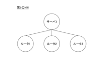
- the topology information acquisition unit 201 acquires topology information G1 of the first NW (step S101).
- topology information G1 representing the network topology shown in Fig. 5 has been acquired.
- "Server 1" in Fig. 5 is the first node
- "Router 1” is the second node
- "Router 2” is the third node
- "Router 3” is the fourth node
- V1 ⁇ 1, 2, 3, 4 ⁇ is set.
- E1 ⁇ e12 (1) , e13 (1) , e14 (1) ⁇ .
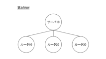
- the topology information acquisition unit 201 acquires topology information G2 of the second NW (step S102).
- the topology information G2 representing the network topology shown in Fig. 6 is acquired.
- "Server 10" in Fig. 6 is the first node
- "Router 10" is the second node
- "Router 20” is the third node
- "Router 30” is the fourth node
- V2 ⁇ 1, 2, 3, 4 ⁇ is set.
- E2 ⁇ e12 (2) , e13 (2) , e14 (2) ⁇ .
- the decision tree creation unit 202 creates a decision tree T1 as an anomaly detection model for the first NW by using the learning data (x, t) ⁇ D stored in the learning data storage unit 205, using a known algorithm such as CART (step S103).
- a known algorithm such as CART
- the correspondence calculation unit 203 uses the topology information G1 of the first NW and the topology information G2 of the second NW to calculate a mapping f that represents a correspondence between each node (device) included in the topology information G1 and each node (device) included in the topology information G2 (step S104).
- the correspondence calculation unit 203 may calculate the mapping f by solving a graph isomorphism problem using a known algorithm such as VF2 (References 1 and 2), Ullmann's algorithm (Reference 3), or the like.
- the decision tree transfer unit 204 creates a decision tree T2 for the second network by using the decision tree T1 and the mapping f (step S105). For example, the decision tree transfer unit 204 creates the decision tree T2 by the following steps 1 and 2.
- Step 1 First, the decision tree transfer unit 204 uses the mapping f to convert the variable x i and the threshold value ⁇ i for that variable that appear in the nodes other than the leaf nodes of the decision tree T1 into the variable y j and the threshold value ⁇ j for that variable, respectively, that is, to find the correspondence relationship.
- variable x1 is a variable representing the traffic volume of "router 1"
- it is converted by the mapping f into a variable representing the traffic volume of "router 10" of the second NW.
- variable x2 is a variable representing the traffic volume of "router 2”
- it is converted by the mapping f into a variable representing the traffic volume of "router 20" of the second NW.
- variable x3 is a variable representing the traffic volume of "router 3”
- variable representing the traffic volume of "router 10" of the second NW is y1
- variable representing the traffic volume of "router 20" of the second NW is y2
- variable representing the traffic volume of "router 30" of the second NW is y3 .
- the thresholds ⁇ 1 , ⁇ 2 , and ⁇ 3 are converted to thresholds ⁇ 1 , ⁇ 2 , and ⁇ 3 for variables y1 , y2 , and y3, respectively.
- the thresholds ⁇ 1 , ⁇ 2 , and ⁇ 3 are formally converted to thresholds ⁇ 1 , ⁇ 2 , and ⁇ 3 (in other words, only the symbolic notation is converted).
- Specific values of the thresholds ⁇ 1 , ⁇ 2 , and ⁇ 3 are calculated in the following step 2.
- Step 2 Next, the decision tree transfer unit 204 obtains the value of each threshold ⁇ i .
- the decision tree transfer unit 204 obtains the value of each threshold ⁇ i .
- the mean of x i is ⁇ xi and the variance is ⁇ xi 2.
- the following formula (1) follows the standard normal distribution.
- ⁇ i ( ⁇ yi / ⁇ xi )( ⁇ i ⁇ xi )+ ⁇ yi (3) In this way, the value of the threshold ⁇ i is determined.
- a known method such as the least squares method may be used.
- FIG. 8 shows an example of the decision tree T 2 obtained from the decision tree T 1 shown in FIG. 7.
- the decision tree T 2 shown in FIG. 8 is composed of nodes n 21 to n 27 , and the conditional formula "y 1 ⁇ 1 " is set in the node n 21 , the conditional formula "y 2 ⁇ 2 " is set in the node n 22 , and the conditional formula "y 3 ⁇ 3 " is set in the node n 24.
- the tree branches to the left, and when not, the tree branches to the right.
- observation values x1, x2, x3, and x4 were obtained from four devices in the first network, and if any of the observation values fell below the threshold value s, the system was determined to be abnormal.
- the observation data was labeled to create learning data.
- 1,000 pieces of observed data (x1, x2, x3, x4) were prepared, with each of the observed values x1, x2, x3, and x4 randomly taking integer values between 1 and 100, and assuming that the observed values x1, x2, x3, and x4 are independent of each other and do not affect each other.
- the classification class was set to the abnormal class (1) when any of x1, x2, x3, and x4 fell below the threshold s, and to the normal class (0) otherwise.
- gini represents the Gini coefficient
- samples represents the number of learning data classified into the node
- value represents the number of learning data belonging to the abnormal class and the number of learning data belonging to the normal class among the learning data classified into the node
- class represents the classification destination class.
- the present invention is not limited to the specifically disclosed embodiments above, and various modifications, changes, and combinations with known technologies are possible without departing from the scope of the claims.
- the present invention is not limited to anomaly detection, but can be similarly applied to any form in which a decision tree is used for a network, such as isolating a fault, acquiring response procedures, and designing a network configuration.
- Reference 1 Luigi P. Cordella, Pasquale Foggia, Carlo Sansone, Mario Vento, "A (Sub)Graph Isomorphism Algorithm for Matching Large Graphs", IEEE Transactions on Pattern Analysis and Machine Intelligence, vol. 26, no. 10, pp. 1367-1372, Oct., 2004.
- Reference 2 L. P. Cordella, P. Foggia, C. Sansone, M. Vento, "An Improved Algorithm for Matching Large Graphs", 3rd IAPR-TC15 Workshop on Graph-based Representations in Pattern Recognition, Cuen, pp. 149-159, 2001.
- Reference 3 ULLMANN, Julian R. An algorithm for subgraph isomorphism. Journal of the ACM (JACM), 1976, 23.1: 31-42.
- Transfer device 101 Input device 102 Display device 103 External I/F 103a Recording medium 104 Communication I/F 105 RAM 106 ROM 107 Auxiliary storage device 108 Processor 109 Bus 201 Topology information acquisition unit 202 Decision tree creation unit 203 Correspondence calculation unit 204 Decision tree transfer unit 205 Learning data storage unit
Landscapes
- Engineering & Computer Science (AREA)
- Computer Networks & Wireless Communication (AREA)
- Signal Processing (AREA)
- Data Exchanges In Wide-Area Networks (AREA)
Abstract
本開示の一態様による転移装置は、第1のNWに関する第1の決定木を第2のNWに転移させるための転移装置であって、前記第1のNWの観測データと、前記観測データに対応するラベルとを用いて、前記第1の決定木を作成する作成部と、前記第1のNWを構成する各ノードと、前記第2のNWを構成する各ノードとの間の対応関係を算出する対応関係算出部と、前記第1の決定木と前記対応関係とを用いて、前記対応関係を利用して前記第1の決定木を変換することにより、前記第2のNWに関する第2の決定木を作成する転移部と、を有する。
Description
本開示は、転移装置、転移方法、及びプログラムに関する。
複数のネットワークソリューションを提供するネットワーク事業者等では、複数のネットワークを管理・運用している。このため、複数のネットワークを管理・運用できる技術等が利用される(例えば、特許文献1)。
また、ネットワーク(以下、NWという。)に生じる異常(例えば、障害、装置故障、負荷増大、人為的ミス等)を検知するための異常検知モデルを決定木により作成し、その異常検知モデルによりNW異常を検知することが行われている。異常検知の他にも、決定木は、例えば、障害時の切り分け、対応手順獲得、NW構成の設計等といったNWの保全や構築の領域で用いられている。これらは、異常検知・切り分け・対応手順・NW構成設計等といったNWの保全や構築に関する知識を決定木の形で表している。
しかしながら、新たにNWを構築した場合等にはそのNWのデータが少ないため、上述したような知識を構築することができない。一方で、或るNW(以下、第1のNWという。)の知識を新たに構築したNW(以下、第2のNWという。)の知識として転移することも考えられるが、仮に第1のNWと第2のNWが類似している場合であってもそれらのNWを構成する装置の名称等が異なるため、そのまま転移することはできない。
本開示は、上記の点に鑑みてなされたもので、第1のNWの知識を第2のNWの知識として転移できる技術を提供する。
本開示の一態様による転移装置は、第1のNWに関する第1の決定木を第2のNWに転移させるための転移装置であって、前記第1のNWの観測データと、前記観測データに対応するラベルとを用いて、前記第1の決定木を作成する作成部と、前記第1のNWを構成する各ノードと、前記第2のNWを構成する各ノードとの間の対応関係を算出する対応関係算出部と、前記第1の決定木と前記対応関係とを用いて、前記対応関係を利用して前記第1の決定木を変換することにより、前記第2のNWに関する第2の決定木を作成する転移部と、を有する。
第1のNWの知識を第2のNWの知識として転移できる技術が提供される。
以下、本発明の一実施形態について説明する。以下の実施形態では、異常検知を例にとり、NWに関する知識として異常検知モデルを想定した上で、第1のNWの異常検知モデルを第2のNWの異常検知モデルとして転移できる転移装置10について説明する。なお、第1のNWの異常検知モデルを第2のNWの異常検知モデルとして転移するとは、第1のNWの異常検知モデルを第2のNWの異常検知モデルとして利用可能とすることを意味する。転移は、例えば、「ポーティング」、「移植」、「移行」等と呼ばれてもよい。
また、以下では、第1のNWとして、異常検知モデルである決定木を作成するのに十分な学習データが収集されているNWを想定する。一方で、第2のNWとしては、例えば、新たに構築したNWや運用後間もないNW等といった理由により異常検知モデルである決定木を作成するのに十分な学習データが収集されていないNWを想定する。更に、第1のNWと第2のNWは互いに類似するが、それらのNWを構成する装置(サーバ、NW装置等)の名称等は異なることを想定する。このとき、第1のNWの異常検知モデルを決定木により作成した上で、この決定木を第2のNWの異常検知モデルとして転移させることが目的である。以下、第1のNWの異常検知モデルとなる決定木をT1、第2のNWの異常検知モデルとなる決定木をT2とする。
<対象NW>
図1に示すように、NWは、一般に、様々なサーバ(Webサーバ、アプリケーションサーバ、データベースサーバ等)やNW装置(ルータ、ゲートウェイ、コアNW装置等)、各種端末等で構成されている。このうち、端末を除いた部分を便宜上コアNW等と呼ぶことにする。NWによって端末はその台数が大きく異なるが、コアNWの構成は類似していることが多い。このため、以下では、第1のNW及び第2のNWとしてコアNWを対象とする。なお、以下では、単に「NW」と表記した場合は端末を除いたNWである「コアNW」を指すものとする。
図1に示すように、NWは、一般に、様々なサーバ(Webサーバ、アプリケーションサーバ、データベースサーバ等)やNW装置(ルータ、ゲートウェイ、コアNW装置等)、各種端末等で構成されている。このうち、端末を除いた部分を便宜上コアNW等と呼ぶことにする。NWによって端末はその台数が大きく異なるが、コアNWの構成は類似していることが多い。このため、以下では、第1のNW及び第2のNWとしてコアNWを対象とする。なお、以下では、単に「NW」と表記した場合は端末を除いたNWである「コアNW」を指すものとする。
<転移装置10のハードウェア構成例>
本実施形態に係る転移装置10のハードウェア構成例を図2に示す。図2に示すように、本実施形態に係る転移装置10は、入力装置101と、表示装置102と、外部I/F103と、通信I/F104と、RAM(Random Access Memory)105と、ROM(Read Only Memory)106と、補助記憶装置107と、プロセッサ108とを有する。これらの各ハードウェアは、それぞれがバス109を介して通信可能に接続される。
本実施形態に係る転移装置10のハードウェア構成例を図2に示す。図2に示すように、本実施形態に係る転移装置10は、入力装置101と、表示装置102と、外部I/F103と、通信I/F104と、RAM(Random Access Memory)105と、ROM(Read Only Memory)106と、補助記憶装置107と、プロセッサ108とを有する。これらの各ハードウェアは、それぞれがバス109を介して通信可能に接続される。
入力装置101は、例えば、キーボード、マウス、タッチパネル、物理ボタン等である。表示装置102は、例えば、ディスプレイ、表示パネル等である。なお、転移装置10は、例えば、入力装置101及び表示装置102のうちの少なくとも一方を有していなくてもよい。
外部I/F103は、記録媒体103a等の外部装置とのインタフェースである。記録媒体103aとしては、例えば、CD(Compact Disc)、DVD(Digital Versatile Disk)、SDメモリカード(Secure Digital memory card)、USB(Universal Serial Bus)メモリカード等が挙げられる。
通信I/F104は、転移装置10が他の装置等と通信を行うためのインタフェースである。RAM105は、プログラムやデータを一時保持する揮発性の半導体メモリ(記憶装置)である。ROM106は、電源を切ってもプログラムやデータを保持することができる不揮発性の半導体メモリ(記憶装置)である。補助記憶装置107は、例えば、HDD(Hard Disk Drive)、SSD(Solid State Drive)、フラッシュメモリ等の不揮発性の記憶装置である。プロセッサ108は、例えば、CPU(Central Processing Unit)やGPGPU(General Purpose computing with Graphic Processing Unit)等の各種演算装置である。
なお、図2に示すハードウェア構成は一例であって、転移装置10は、複数の補助記憶装置107や複数のプロセッサ108を有していてもよいし、図示したハードウェアの一部を有していなくてもよいし、図示したハードウェア以外の種々のハードウェアを有していてもよい。
<転移装置10の機能構成例>
本実施形態に係る転移装置10の機能構成例を図3に示す。図3に示すように、本実施形態に係る転移装置10は、トポロジ情報取得部201と、決定木作成部202と、対応関係算出部203と、決定木転移部204とを有する。これら各部は、例えば、転移装置10にインストールされた1以上のプログラムが、プロセッサ108等に実行させる処理により実現される。また、本実施形態に係る転移装置10は、学習データ記憶部205を有する。学習データ記憶部205は、例えば、補助記憶装置107等により実現される。なお、学習データ記憶部205は、例えば、転移装置10と通信可能に接続されるデータベース等により実現されてもよい。
本実施形態に係る転移装置10の機能構成例を図3に示す。図3に示すように、本実施形態に係る転移装置10は、トポロジ情報取得部201と、決定木作成部202と、対応関係算出部203と、決定木転移部204とを有する。これら各部は、例えば、転移装置10にインストールされた1以上のプログラムが、プロセッサ108等に実行させる処理により実現される。また、本実施形態に係る転移装置10は、学習データ記憶部205を有する。学習データ記憶部205は、例えば、補助記憶装置107等により実現される。なお、学習データ記憶部205は、例えば、転移装置10と通信可能に接続されるデータベース等により実現されてもよい。
トポロジ情報取得部201は、第1のNWのネットワークトポロジ(グラフ構造)を表すトポロジ情報と、第2のNWのネットワークトポロジ(グラフ構造)を表すトポロジ情報とを取得する。なお、トポロジ情報取得部201は、例えば、SNMP(Simple Network Management Protocol)、LLDP(Link Layer Discovery Protocol)、NW装置独自のプロトコル、OSPF(Open Shortest Path First)をはじめとするルーティングプロトコル等を利用して第1のNW及び第2のNWのトポロジ情報を取得することが可能である。
以下、第1のNWのトポロジ情報をG1=(V1,E1)、第2のNWのトポロジ情報をG2=(V2,E2)と表す。ここで、V1は第1のNWを構成するノード(例えば、サーバ、NW装置等)の集合、E1はノード間を接続するエッジの集合である。同様に、V2は第2のNWを構成するノードの集合、E2はノード間を接続するエッジの集合である。
決定木作成部202は、学習データ記憶部205に記憶されている学習データを用いて、第1のNWの異常検知モデルとして決定木T1を作成する。決定木作成部202は、例えば、CART等といった既知のアルゴリズムにより決定木T1を作成すればよい。なお、CARTではジニ係数(不純度)と呼ばれる指標値を使用して統計的に偏りが大きくなるように木を分割することにより決定木が作成される。
ここで、学習データとは、第1のNWが正常又は異常のいずれであるかを表すラベル付きの観測データのことである。観測データとは、第1のNWを構成する或る1つ以上の装置から収集されたデータ(観測値)で構成される観測データのことである。例えば、n台の装置が観測対象として観測値が収集される場合、n台の装置のうちのi番目の装置の観測値をxiとして、観測データはx=(x1,・・・,xn)と表される。観測値の種類としては、例えば、トラヒック量、CPU使用率、メモリ使用量、温度、ログ等といったものが挙げられる。
また、決定木T1は観測データxを入力として系(つまり、第1のNW)が正常又は異常のいずれであるかを表すラベルt∈{0,1}(ただし、t=0は正常、t=1は異常を表す。)を出力するモデルである。決定木T1では、葉ノード以外のノードには或る観測値を表す変数xiとそれに対する閾値θiに関する条件式(例えば、xi≦θi)が設定され、葉ノードには最終的に出力されるラベルtが設定される。
以下、第1のNWの観測データを構成する各観測値xi(i=1,・・・,n)は互いに独立であるものとする。同様に、第2のNWの観測データをy=(y1,・・・,yn)としたとき、各観測値yi(i=1,・・・,n)は互いに独立であるものとする。
また、第1のNWのグラフ構造的に対等な位置関係にある観測値xi及びxjは同一種類の観測値であり、互いに入れ替え可能であるものとする。以下では、簡単のため、任意の観測値xi及びxjは互いに入れ替え可能であることを想定する。なお、入れ替え可能であるとは、例えば、n=3のとき、x=(x1,x2,x3)、x=(x1,x3,x2)、x=(x2,x1,x3)、x=(x2,x3,x1)、x=(x3,x1,x2)、x=(x3,x2,x1)のいずれを決定木T1に入力しても出力tが変化しないことを意味する。
対応関係算出部203は、第1のNWのトポロジ情報G1に含まれる各ノードと、第2のNWのトポロジ情報G2に含まれる各ノードとの対応関係を算出する。以下、この対応関係を写像fで表す。対応関係算出部203は、例えば、VF2(参考文献1、2)、Ullmannのアルゴリズム(参考文献3)等といった既知のアルゴリズムによりグラフ同型問題を解くことによって写像fを算出すればよい。
決定木転移部204は、決定木T1と写像fとを用いて、第2のNWの決定木T2を作成する。すなわち、決定木転移部204は、決定木T1の葉ノード以外のノード中に出現する変数xi(i=1,・・・,n)を写像fにより第2のNWの或る観測値を表す変数yjに変換すると共にその変数xiに対する閾値θiを変数yjに対する閾値φjに変換した上で、各閾値φjの値を算出する。これにより、葉ノード以外のノードには或る観測値を表す変数yjとそれに対する閾値φjに関する条件式(例えば、yj≦φj)が設定され、かつ、葉ノードには最終的に出力されるラベルtが設定された決定木T2が得られる。つまり、決定木T1が第2のNWの異常検知モデルである決定木T2として転移されたことになる。
学習データ記憶部205は、決定木T1の作成に用いられる学習データの集合(学習データセット)を記憶する。ここで、学習データは、観測データxと、それに対するラベルtとの組で表される。すなわち、学習データセットはD={(x(i),t(i))|i=1,・・・,|D|}と表される。なお、学習データセットDは事前に収集され、学習データ記憶部205に記憶される。
<決定木の作成及び転移処理>
以下、第1のNWの異常検知モデルとして決定木T1を作成した上で、その決定木T1を第2のNWの異常検知モデルとして転移させる処理について、図4を参照しながら説明する。
以下、第1のNWの異常検知モデルとして決定木T1を作成した上で、その決定木T1を第2のNWの異常検知モデルとして転移させる処理について、図4を参照しながら説明する。
まず、トポロジ情報取得部201は、第1のNWのトポロジ情報G1を取得する(ステップS101)。以下、一例として、図5に示すネットワークトポロジを表すトポロジ情報G1が取得されたものとする。また、このとき、図5の「サーバ1」を1番目のノード、「ルータ1」を2番目のノード、「ルータ2」を3番目のノード、「ルータ3」を4番目のノードとして、V1={1,2,3,4}とする。なお、例えば、第1のNWのi番目のノードとj番目のノードとの間のエッジをeij
(1)とすれば、E1={e12
(1),e13
(1),e14
(1)}である。
次に、トポロジ情報取得部201は、第2のNWのトポロジ情報G2を取得する(ステップS102)。以下、一例として、図6に示すネットワークトポロジを表すトポロジ情報G2が取得されたものとする。また、このとき図6の「サーバ10」を1番目のノード、「ルータ10」を2番目のノード、「ルータ20」を3番目のノード、「ルータ30」を4番目のノードとして、V2={1,2,3,4}とする。なお、例えば、第2のNWのi番目のノードとj番目のノードとの間のエッジをeij
(2)とすれば、E2={e12
(2),e13
(2),e14
(2)}である。
次に、決定木作成部202は、学習データ記憶部205に記憶されている学習データ(x,t)∈Dを用いて、CART等といった既知のアルゴリズムにより、第1のNWの異常検知モデルとして決定木T1を作成する(ステップS103)。以下、一例として、観測データはx=(x1,x2,x3)(ただし、x1はルータ1のトラヒック量、x2はルータ2のトラヒック量、x3はルータ3のトラヒック量)であるものとして、図7に示す決定木T1が作成されたものとする。図7に示す決定木T1はノードn11~n17で構成されており、ノードn11には条件式「x1≦θ1」、ノードn12には条件式「x2≦θ2」、ノードn14には条件式「x3≦θ3」がそれぞれ設定されており、当該条件式を満たすときは左、そうでないときは右に分岐する。また、ノードn16には「正常」(t=0)、ノードn13、n15、n17には異常(t=1)がそれぞれ設定されている。
次に、対応関係算出部203は、第1のNWのトポロジ情報G1と、第2のNWのトポロジ情報G2とを用いて、当該トポロジ情報G1に含まれる各ノード(装置)と、当該トポロジ情報G2に含まれる各ノード(装置)との間の対応関係を表す写像fを算出する(ステップS104)。対応関係算出部203は、例えば、VF2(参考文献1、2)、Ullmannのアルゴリズム(参考文献3)等といった既知のアルゴリズムによりグラフ同型問題を解くことによって写像fを算出すればよい。
一例として、以下の対応関係を表す写像f:V1→V2が算出されたものとする。
1=f(1)
2=f(2)
3=f(3)
4=f(4)
なお、1∈V1は「サーバ1」、2∈V1は「ルータ1」、3∈V1は「ルータ2」、4∈V1は「ルータ3」を表す。また、1∈V2は「サーバ10」、2∈V2は「ルータ10」、3∈V2は「ルータ20」、4∈V2は「ルータ30」を表す。
2=f(2)
3=f(3)
4=f(4)
なお、1∈V1は「サーバ1」、2∈V1は「ルータ1」、3∈V1は「ルータ2」、4∈V1は「ルータ3」を表す。また、1∈V2は「サーバ10」、2∈V2は「ルータ10」、3∈V2は「ルータ20」、4∈V2は「ルータ30」を表す。
そして、決定木転移部204は、決定木T1と写像fとを用いて、第2のNWの決定木T2を作成する(ステップS105)。例えば、決定木転移部204は、以下の手順1~手順2により決定木T2を作成する。
手順1:まず、決定木転移部204は、写像fを用いて、決定木T1の葉ノード以外のノード中に出現する変数xiとその変数に対する閾値θiを変数yjとその変数に対する閾値φjにそれぞれ変換、すなわち対応関係を求める。
例えば、変数x1は「ルータ1」のトラヒック量を表す変数であるため、写像fにより、第2のNWの「ルータ10」のトラヒック量を表す変数に変換される。同様に、変数x2は「ルータ2」のトラヒック量を表す変数であるため、写像fにより、第2のNWの「ルータ20」のトラヒック量を表す変数に変換される。同様に、変数x3は「ルータ3」のトラヒック量を表す変数であるため、写像fにより、第2のNWの「ルータ30」のトラヒック量を表す変数に変換される。以下、簡単のため、第2のNWの「ルータ10」のトラヒック量を表す変数をy1、第2のNWの「ルータ20」のトラヒック量を表す変数をy2、第2のNWの「ルータ30」のトラヒック量を表す変数をy3とする。
同様に、閾値θ1、θ2、θ3は、それぞれ変数y1、y2、y3に対する閾値φ1、φ2、φ3に変換される。なお、手順1では閾値θ1、θ2、θ3を形式的に閾値φ1、φ2、φ3に変換(言い換えれば、記号の表記のみを変換)している点に留意されたい。閾値φ1、φ2、φ3の具体的な値は次の手順2で算出される。
手順2:次に、決定木転移部204は、各閾値φiの値を求める。以下、各iに対してyi=αxi+βとの関係があるものとして、閾値φiの値を求める2つの方法を説明する。なお、yi=αxi+βと仮定できるのは、例えば、i=1を考えた場合、「ルータ1」と「ルータ10」はCPUのコア数が違う等の差異があるため、y1はx1をα倍してオフセットβを加えたもので表現できると考えられるためである。
・方法1
xiもyiも正規分布に従うものとする。また、xiの平均と分散は観測値から既に得られているものとする。一方で、yiの平均と分散は、既知であるxiに関する知見(観測値、平均、分散等)に基づいて人手で与えられてもよいし、yiの観測値が得られている場合にはそれらの観測値から平均、分散を求めてもよい。
xiもyiも正規分布に従うものとする。また、xiの平均と分散は観測値から既に得られているものとする。一方で、yiの平均と分散は、既知であるxiに関する知見(観測値、平均、分散等)に基づいて人手で与えられてもよいし、yiの観測値が得られている場合にはそれらの観測値から平均、分散を求めてもよい。
xiの平均をμxi、分散をσxi
2とする。このとき、以下の式(1)は標準正規分布に従う。
Zxi=(xi-μxi)/σxi (1)
同様に、yiの平均をμyi、分散をσyi 2とする。このとき、以下の式(2)は標準正規分布に従う。
同様に、yiの平均をμyi、分散をσyi 2とする。このとき、以下の式(2)は標準正規分布に従う。
Zyi=(yi-μyi)/σyi (2)
φiはθiに対応するため、式(1)においてxi=θi、式(2)においてyi=φiを代入し、Zxi=Zyiとした方程式を解けば以下の式(3)が得られる。
φiはθiに対応するため、式(1)においてxi=θi、式(2)においてyi=φiを代入し、Zxi=Zyiとした方程式を解けば以下の式(3)が得られる。
φi=(σyi/σxi)(θi-μxi)+μyi (3)
これにより、閾値φiの値が求まる。
これにより、閾値φiの値が求まる。
・方法2
yi=αxi+βのα及びβを回帰分析により求める。これにより、φi=αθi+βにより閾値φiの値が求まる。回帰分析は、例えば、最小二乗法等の既知の手法を用いればよい。
yi=αxi+βのα及びβを回帰分析により求める。これにより、φi=αθi+βにより閾値φiの値が求まる。回帰分析は、例えば、最小二乗法等の既知の手法を用いればよい。
なお、方法1と比べて、方法2では回帰係数α及びβを求めるのは計算コストが高いが、決定木T1の中に或る変数xiに関する条件式が複数箇所出現するような場合には、それら複数箇所の変数xiに関する条件式θiに対応するφiを求める際に、一度yi=αxi+βの回帰係数α及びβを求めた結果を使い回せばよいため、方法2でも効率的である。
以上により、決定木T1に含まれる変数xi及びその閾値θiが変数yj及びその閾値φjに変換され、決定木T2が得られる。図7に示す決定木T1から得られた決定木T2の一例を図8に示す。図8に示す決定木T2はノードn21~n27で構成されており、ノードn21には条件式「y1≦φ1」、ノードn22には条件式「y2≦φ2」、ノードn24には条件式「y3≦φ3」がそれぞれ設定されており、当該条件式を満たすときは左、そうでないときは右に分岐する。また、ノードn26には「正常」(t=0)、ノードn23、n25、n27には異常(t=1)がそれぞれ設定されている。これにより、決定木T1を第2のNWの異常検知モデルとして転移した決定木T2が得られたことになる。
<実験>
・実験1
上記の実施形態では、第1のNWのグラフ構造的に対等な位置関係にある観測値xi及びxjは互いに入れ替え可能であることを仮定したが、この仮定が異常検知に影響がないことを実験にて確認した。
・実験1
上記の実施形態では、第1のNWのグラフ構造的に対等な位置関係にある観測値xi及びxjは互いに入れ替え可能であることを仮定したが、この仮定が異常検知に影響がないことを実験にて確認した。
本実験では、第1のNW中の4台の装置から観測値x1,x2,x3,x4が得られ、いずれかの観測値で閾値sを下回った場合に系は異常であると判定するものとして、観測データに対してラベル付けを行って学習データを作成した。
また、観測値x1,x2,x3,x4の各々は1~100の整数値をランダムに取り、観測値x1,x2,x3,x4は互いに独立で影響しあっていないものとして、1000個の観測データ(x1,x2,x3,x4)を準備した。分類先クラスは、x1,x2,x3,x4のいずれかが閾値sを下回ったときは異常クラス(1)、それ以外のときは正常クラス(0)とした。
閾値s=10のときに作成された決定木T1を図9、閾値s=30のときに作成された決定木T1を図10、閾値s=50のときに作成された決定木T1を図11にそれぞれ示す。なお、図9~図11中でginiはジニ係数を表し、samplesはそのノードに分類された学習データ数、valueはそのノードに分類された学習データのうち、異常クラスに属する学習データ数と正常クラスに属する学習データ数、classは分類先クラスをそれぞれ表す。
図9~図11により、変数x1,x2,x3,x4を入れ替えても決定木T1の出力には影響がないことがわかる。
・実験2
100前後のノード数で構成される第1のNW及び第2のNWを対象として、既存のVF2アルゴリズムにより、グラフ同型問題の解を1つ得る実験を行い、1秒程度の計算時間により写像fが得られることを確認した。これにより、少なくとも100前後のノード数で構成される第1のNW及び第2のNWに関しては実用的な時間で写像fが求まることがわかる。
100前後のノード数で構成される第1のNW及び第2のNWを対象として、既存のVF2アルゴリズムにより、グラフ同型問題の解を1つ得る実験を行い、1秒程度の計算時間により写像fが得られることを確認した。これにより、少なくとも100前後のノード数で構成される第1のNW及び第2のNWに関しては実用的な時間で写像fが求まることがわかる。
<まとめ>
以上のように、本実施形態に係る転移装置10は、第1のNWの異常検知モデルとして作成された決定木T1を第2のNWの異常検知モデル(決定木T2)として転移することができる。このため、例えば、第1のNWは十分な学習データがある一方で、第2のNWは運用後間もない等の理由により十分な学習データがない場合等であっても、第2のNWの異常検知モデルとして決定木T2を得ることが可能になる。しかも、決定木T1の変数名とその変数に対する閾値を変換することにより決定木T2を作成できるため、例えば、決定木T2を学習データから作成するよりも高速に促成することが可能となる。
以上のように、本実施形態に係る転移装置10は、第1のNWの異常検知モデルとして作成された決定木T1を第2のNWの異常検知モデル(決定木T2)として転移することができる。このため、例えば、第1のNWは十分な学習データがある一方で、第2のNWは運用後間もない等の理由により十分な学習データがない場合等であっても、第2のNWの異常検知モデルとして決定木T2を得ることが可能になる。しかも、決定木T1の変数名とその変数に対する閾値を変換することにより決定木T2を作成できるため、例えば、決定木T2を学習データから作成するよりも高速に促成することが可能となる。
本発明は、具体的に開示された上記の実施形態に限定されるものではなく、請求の範囲の記載から逸脱することなく、種々の変形や変更、既知の技術との組み合わせ等が可能である。例えば、本発明は、異常検知に限らず、障害時の切り分け、対応手順獲得、NW構成の設計等、NWに関して決定木が用いられる形態であれば同様に適用することが可能である。
[参考文献]
参考文献1:Luigi P. Cordella, Pasquale Foggia, Carlo Sansone, Mario Vento, "A (Sub)Graph Isomorphism Algorithm for Matching Large Graphs", IEEE Transactions on Pattern Analysis and Machine Intelligence, vol. 26, no. 10, pp. 1367-1372, Oct., 2004.
参考文献2:L. P. Cordella, P. Foggia, C. Sansone, M. Vento, "An Improved Algorithm for Matching Large Graphs", 3rd IAPR-TC15 Workshop on Graph-based Representations in Pattern Recognition, Cuen, pp. 149-159, 2001.
参考文献3:ULLMANN, Julian R. An algorithm for subgraph isomorphism. Journal of the ACM (JACM), 1976, 23.1: 31-42.
参考文献1:Luigi P. Cordella, Pasquale Foggia, Carlo Sansone, Mario Vento, "A (Sub)Graph Isomorphism Algorithm for Matching Large Graphs", IEEE Transactions on Pattern Analysis and Machine Intelligence, vol. 26, no. 10, pp. 1367-1372, Oct., 2004.
参考文献2:L. P. Cordella, P. Foggia, C. Sansone, M. Vento, "An Improved Algorithm for Matching Large Graphs", 3rd IAPR-TC15 Workshop on Graph-based Representations in Pattern Recognition, Cuen, pp. 149-159, 2001.
参考文献3:ULLMANN, Julian R. An algorithm for subgraph isomorphism. Journal of the ACM (JACM), 1976, 23.1: 31-42.
10 転移装置
101 入力装置
102 表示装置
103 外部I/F
103a 記録媒体
104 通信I/F
105 RAM
106 ROM
107 補助記憶装置
108 プロセッサ
109 バス
201 トポロジ情報取得部
202 決定木作成部
203 対応関係算出部
204 決定木転移部
205 学習データ記憶部
101 入力装置
102 表示装置
103 外部I/F
103a 記録媒体
104 通信I/F
105 RAM
106 ROM
107 補助記憶装置
108 プロセッサ
109 バス
201 トポロジ情報取得部
202 決定木作成部
203 対応関係算出部
204 決定木転移部
205 学習データ記憶部
Claims (7)
- 第1のNWに関する第1の決定木を第2のNWに転移させるための転移装置であって、
前記第1のNWの観測データと、前記観測データに対応するラベルとを用いて、前記第1の決定木を作成する作成部と、
前記第1のNWを構成する各ノードと、前記第2のNWを構成する各ノードとの間の対応関係を算出する対応関係算出部と、
前記第1の決定木と前記対応関係とを用いて、前記対応関係を利用して前記第1の決定木を変換することにより、前記第2のNWに関する第2の決定木を作成する転移部と、
を有する転移装置。 - 前記転移部は、
前記第1の決定木の葉ノード以外の各ノードに設定されている変数と前記変数に対する閾値を前記対応関係により変換し、変換後の閾値の値を求めることにより、前記第2の決定木を作成する、請求項1に記載の転移装置。 - 前記転移部は、
前記変数をx、前記変換後の変数をyとしたとき、y=αx+βと表せる場合、前記変数x及び前記変換後の変数yがいずれも正規分布に従うとの仮定の下、φ=(σy/σx)(θ-μx)+μy(ただし、φは前記変換後の変数yに対する閾値、θは前記変数xに対する閾値、μxは前記変数xの観測値の平均、σxは前記変数xの観測値の標準偏差、μyは前記変換後の変数yの観測値の平均、σyは前記変換後の変数yの観測値の標準偏差)により前記変換後の閾値φの値を求める、請求項2に記載の転移装置。 - 前記転移部は、
前記変数をx、前記変換後の変数をyとしたとき、y=αx+βと表せる場合、回帰分析によりα,βを算出し、φ=αθ+β(ただし、φは前記変換後の変数yに対する閾値、θは前記変数xに対する閾値)により前記変換後の閾値φの値を求める、請求項2に記載の転移装置。 - 前記対応関係算出部は、
前記第1のNWのネットワークトポロジを表すトポロジ情報と、前記第2のNWのネットワークトポロジを表すトポロジ情報とを用いて、グラフ同型問題を解くことにより、前記対応関係を表す写像を算出する、請求項1乃至4の何れか一項に記載の転移装置。 - 第1のNWに関する第1の決定木を第2のNWに転移させるためのコンピュータが、
前記第1のNWの観測データと、前記観測データに対応するラベルとを用いて、前記第1の決定木を作成する作成手順と、
前記第1のNWを構成する各ノードと、前記第2のNWを構成する各ノードとの間の対応関係を算出する対応関係算出手順と、
前記第1の決定木と前記対応関係とを用いて、前記対応関係を利用して前記第1の決定木を変換することにより、前記第2のNWに関する第2の決定木を作成する転移手順と、
を実行する転移方法。 - 第1のNWに関する第1の決定木を第2のNWに転移させるためのコンピュータに、
前記第1のNWの観測データと、前記観測データに対応するラベルとを用いて、前記第1の決定木を作成する作成手順と、
前記第1のNWを構成する各ノードと、前記第2のNWを構成する各ノードとの間の対応関係を算出する対応関係算出手順と、
前記第1の決定木と前記対応関係とを用いて、前記対応関係を利用して前記第1の決定木を変換することにより、前記第2のNWに関する第2の決定木を作成する転移手順と、
を実行させるプログラム。
Priority Applications (2)
| Application Number | Priority Date | Filing Date | Title |
|---|---|---|---|
| JP2025525550A JPWO2024252587A1 (ja) | 2023-06-07 | 2023-06-07 | |
| PCT/JP2023/021235 WO2024252587A1 (ja) | 2023-06-07 | 2023-06-07 | 転移装置、転移方法、及びプログラム |
Applications Claiming Priority (1)
| Application Number | Priority Date | Filing Date | Title |
|---|---|---|---|
| PCT/JP2023/021235 WO2024252587A1 (ja) | 2023-06-07 | 2023-06-07 | 転移装置、転移方法、及びプログラム |
Publications (1)
| Publication Number | Publication Date |
|---|---|
| WO2024252587A1 true WO2024252587A1 (ja) | 2024-12-12 |
Family
ID=93795738
Family Applications (1)
| Application Number | Title | Priority Date | Filing Date |
|---|---|---|---|
| PCT/JP2023/021235 Ceased WO2024252587A1 (ja) | 2023-06-07 | 2023-06-07 | 転移装置、転移方法、及びプログラム |
Country Status (2)
| Country | Link |
|---|---|
| JP (1) | JPWO2024252587A1 (ja) |
| WO (1) | WO2024252587A1 (ja) |
Citations (2)
| Publication number | Priority date | Publication date | Assignee | Title |
|---|---|---|---|---|
| JP2010166240A (ja) * | 2009-01-14 | 2010-07-29 | Panasonic Corp | 端末装置およびパケット送信方法 |
| JP2010193224A (ja) * | 2009-02-19 | 2010-09-02 | Nippon Telegr & Teleph Corp <Ntt> | ネットワーク設計装置、ネットワーク設計方法、およびプログラム |
-
2023
- 2023-06-07 WO PCT/JP2023/021235 patent/WO2024252587A1/ja not_active Ceased
- 2023-06-07 JP JP2025525550A patent/JPWO2024252587A1/ja active Pending
Patent Citations (2)
| Publication number | Priority date | Publication date | Assignee | Title |
|---|---|---|---|---|
| JP2010166240A (ja) * | 2009-01-14 | 2010-07-29 | Panasonic Corp | 端末装置およびパケット送信方法 |
| JP2010193224A (ja) * | 2009-02-19 | 2010-09-02 | Nippon Telegr & Teleph Corp <Ntt> | ネットワーク設計装置、ネットワーク設計方法、およびプログラム |
Also Published As
| Publication number | Publication date |
|---|---|
| JPWO2024252587A1 (ja) | 2024-12-12 |
Similar Documents
| Publication | Publication Date | Title |
|---|---|---|
| US7631222B2 (en) | Method and apparatus for correlating events in a network | |
| US10511613B2 (en) | Knowledge transfer system for accelerating invariant network learning | |
| Zhao et al. | Towards faithful and consistent explanations for graph neural networks | |
| Wang et al. | Identify critical nodes in network cascading failure based on data analysis | |
| CN118802651B (zh) | 基于公共计算环境的舰船电子信息系统故障传播路径识别方法 | |
| de Farias et al. | A multisensor data fusion algorithm using the hidden correlations in Multiapplication Wireless Sensor data streams | |
| WO2024199174A1 (zh) | 一种异常检测方法及相关设备 | |
| Liu et al. | Jordan Form‐Based Algebraic Conditions for Controllability of Multiagent Systems under Directed Graphs | |
| CN115833395A (zh) | 一种配电网的运行状态的分析方法、装置及在线监测系统 | |
| JP7414135B2 (ja) | モデル構築装置、推定装置、モデル構築方法、推定方法及びプログラム | |
| CN115119241B (zh) | 一种无线传感器网络链路故障检测方法 | |
| Zhai et al. | An auditing language for preventing correlated failures in the cloud | |
| CN119579147B (zh) | 基于深度学习的变电站站端网络设备消缺校核方法及系统 | |
| CN116886560A (zh) | 多层网络可靠性评估方法、装置、电子设备及存储介质 | |
| Li et al. | Kano: Efficient container network policy verification | |
| CN112966368A (zh) | 一种考虑共因失效pms的可靠性评估方法 | |
| CN118798346A (zh) | 一种基于因果图的代价最小必要因故障根因定位方法、系统及计算机可读存储介质 | |
| Yu et al. | Hrca: A heterogeneous graph-based adaptive root cause analysis framework | |
| Neidig et al. | Decentralised diagnosis of automata networks | |
| Fan et al. | Machine learning based optical transmission system link performance degradation prediction and application | |
| US9123008B2 (en) | Buildable part pairs in an unconfigured product structure | |
| WO2025094392A1 (ja) | 転移装置及び転移方法 | |
| Liu et al. | Machine learning for robust network design: A new perspective | |
| JP7635846B2 (ja) | 信頼性計算方法、信頼性計算装置、及びプログラム | |
| US20240378474A1 (en) | Multi cloud network verification using quantum machine learning |
Legal Events
| Date | Code | Title | Description |
|---|---|---|---|
| 121 | Ep: the epo has been informed by wipo that ep was designated in this application |
Ref document number: 23940688 Country of ref document: EP Kind code of ref document: A1 |
|
| ENP | Entry into the national phase |
Ref document number: 2025525550 Country of ref document: JP Kind code of ref document: A |
|
| NENP | Non-entry into the national phase |
Ref country code: DE |