WO2024252568A1 - バランス改善装置、バランス改善方法、およびバランス改善プログラム - Google Patents
バランス改善装置、バランス改善方法、およびバランス改善プログラム Download PDFInfo
- Publication number
- WO2024252568A1 WO2024252568A1 PCT/JP2023/021186 JP2023021186W WO2024252568A1 WO 2024252568 A1 WO2024252568 A1 WO 2024252568A1 JP 2023021186 W JP2023021186 W JP 2023021186W WO 2024252568 A1 WO2024252568 A1 WO 2024252568A1
- Authority
- WO
- WIPO (PCT)
- Prior art keywords
- balance
- user
- tactile
- body position
- ultrasonic
- Prior art date
- Legal status (The legal status is an assumption and is not a legal conclusion. Google has not performed a legal analysis and makes no representation as to the accuracy of the status listed.)
- Ceased
Links
Images



Classifications
-
- A—HUMAN NECESSITIES
- A63—SPORTS; GAMES; AMUSEMENTS
- A63B—APPARATUS FOR PHYSICAL TRAINING, GYMNASTICS, SWIMMING, CLIMBING, OR FENCING; BALL GAMES; TRAINING EQUIPMENT
- A63B22/00—Exercising apparatus specially adapted for conditioning the cardio-vascular system, for training agility or co-ordination of movements
Definitions
- the present invention relates to a balance improvement device, a balance improvement method, and a balance improvement program.
- Non-Patent Document 1 This phenomenon is called light touch, and occurs when a fixed point such as a wall is touched with a force of less than 1N.
- the principle is that when the contact situation with the fixed point changes due to center of gravity sway, the delicate tactile receptors in the hands sense this, quickly detecting the body's unsteadiness and allowing balance to be restored, thereby reducing center of gravity sway.
- the present invention was made in light of the above-mentioned circumstances, and its purpose is to provide a balance improvement device, a balance improvement method, and a balance improvement program that improve standing balance using light touch without the need for a fixed object.
- the balance improvement device includes a body position detection unit, a tactile stimulus control unit, and a tactile stimulus presentation unit.
- the body position detection unit detects the body position of at least a part of the user's body.
- the tactile stimulus control unit controls parameters for presenting a tactile stimulus to the detected body position.
- the tactile stimulus presentation unit presents a tactile stimulus to the detected body position in a non-contact manner.
- One aspect of the present invention is a balance improvement method for reducing the sway of the user's center of gravity when standing.
- the balance improvement method includes the steps of detecting the body position of at least a part of the user's body, controlling parameters for presenting a tactile stimulus to the detected body position, and presenting the tactile stimulus to the detected body position in a non-contact manner.
- One aspect of the present invention is a balance improvement program for reducing the user's center of gravity sway when standing.
- the balance improvement program causes a computer having a processor and a storage device to execute at least a part of the control executed by the tactile stimulation control unit of the balance improvement device.
- the present invention provides a balance improvement device, a balance improvement method, and a balance improvement program that improve standing balance using light touch without the need for a fixed object.
- FIG. 1 is a block diagram showing a functional configuration of a balance improvement device according to an embodiment.
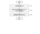
- FIG. 2 is a flowchart showing a flow of processing executed by the balance improvement device according to the embodiment.
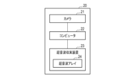
- FIG. 3 is a block diagram showing a functional configuration of a balance improvement device according to an implementation example.
- FIG. 4 is a flowchart showing the flow of processing executed by the balance improvement device according to the implementation example.
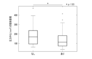
- FIG. 5 shows the results of an experiment on the reduction of body sway when standing on both feet with eyes closed for 30 seconds.
- FIG. 6 is a block diagram showing the hardware configuration of a computer that constitutes the tactile stimulation control unit of the balance improvement device.
- Fig. 1 is a block diagram showing a functional configuration of the balance improvement device 10 according to an embodiment.
- the balance improvement device 10 is a device for reducing sway of the center of gravity of a user when in a standing position.
- the balance improvement device 10 includes a body position detection unit 11, a tactile stimulus control unit 12, and a tactile stimulus presentation unit 13.
- the body position detection unit 11 detects the body position of at least a part of the user's body.
- the tactile stimulus control unit 12 controls the parameters of the tactile stimulus presentation unit 13 so as to present a tactile stimulus to the body position detected by the body position detection unit 11.
- the tactile stimulus presentation unit 13 operates according to the parameters controlled by the tactile stimulus control unit 12, thereby localizing the tactile stimulus to the body position detected by the body position detection unit 11 and presenting it in a non-contact manner.
- Fig. 2 is a flowchart showing the flow of the balance improvement process executed by the balance improvement device 10 according to the embodiment.
- step S11 the body position detection unit 11 detects the body position of at least a part of the user's body.
- the body position detection unit 11 outputs information about the detected body position to the tactile stimulation control unit 12.
- step S12 the tactile stimulation control unit 12 controls the parameters of the tactile stimulation presentation unit 13 so as to present a tactile stimulation to the body position based on the body position information input from the body position detection unit 11.
- step S13 the tactile stimulation presentation unit 13 operates according to parameters controlled by the tactile stimulation control unit 12 to localize the tactile stimulation to the body position detected by the body position detection unit 11 and present it in a non-contact manner.
- Fig. 3 is a block diagram showing the functional configuration of a balance improvement device 20 according to an implementation example.
- the balance improvement device 20 includes a camera 21 that constitutes the body position detection unit 11, a computer 22 that constitutes the tactile stimulation control unit 12, and an ultrasonic focusing device 23 that constitutes the tactile stimulation presentation unit 13.
- Camera 21 has the function of detecting the position of each part of the subject.
- camera 21 incorporates AI (artificial intelligence) and computer vision technology. This allows camera 21 to detect the position of each part of the photographed subject, for example, the user's hand. Camera 21 outputs information on the detected position of the user's hand to computer 22.
- AI artificial intelligence
- computer vision technology This allows camera 21 to detect the position of each part of the photographed subject, for example, the user's hand.
- Camera 21 outputs information on the detected position of the user's hand to computer 22.
- the ultrasonic focusing device 23 irradiates ultrasonic waves as a tactile stimulus.
- the ultrasonic focusing device 23 has an ultrasonic array 24.
- the ultrasonic array 24 is a structure in which multiple ultrasonic transducers are arranged.
- the ultrasonic focusing device 23 can focus the ultrasonic waves generated from the ultrasonic array 24 by phase control.
- the ultrasonic focusing device 23 can adjust the power of the ultrasonic waves generated from the ultrasonic array 24 by amplitude control.
- the computer 22 is, for example, a PC (personal computer). Based on the information on the position of the user's hand input from the camera 21, the computer 22 controls the parameters of the ultrasonic converging device 23 so that the ultrasonic waves emitted from the ultrasonic converging device 23 converge at the position of the user's hand. For example, the computer 22 controls parameters related to the phase of the ultrasonic waves generated from the ultrasonic array 24, thereby converging the ultrasonic waves emitted from the ultrasonic converging device 23 at the position of the user's hand.
- PC personal computer
- the computer 22 also controls parameters related to the amplitude of the ultrasonic waves generated from the ultrasonic array 24 so that the ultrasonic waves converged at the position of the user's hand provide the user with weak tactile feedback of 1N or less.
- Tactile feedback is a stimulus that makes the user feel the same sensation that a user feels when touching a fixed object.
- the ultrasound emitted from the ultrasound converging device 23 converges to a single point at the position of the user's hand, providing the user with weak tactile feedback of less than 1N.
- This weak tactile feedback being presented to a single point on the fingertips or palm gives the user the same sensation as touching a fixed object such as a wall with the hand or fingertips.
- Fig. 4 is a flowchart showing the flow of the balance improvement process executed by the balance improvement device 20.
- step S21 the balance improvement device 20 detects the position of the user's hands with the camera 21.
- the camera 21 outputs information about the detected position of the user's hands to the computer 22.
- step S22 the computer 22 controls parameters related to the phase of the ultrasound generated from the ultrasound array 24, based on the information on the position of the user's hand input from the camera 21, so that the ultrasound emitted from the ultrasound focusing device 23 converges to a single point at the position of the user's hand.
- the computer 22 also controls parameters related to the amplitude of the ultrasound generated from the ultrasound array 24, so that the ultrasound converged at the position of the user's hand provides the user with weak tactile feedback of 1 N or less.
- step S23 the ultrasonic focusing device 23 operates according to parameters controlled by the computer 22, and emits ultrasonic waves from the ultrasonic array 24.
- the ultrasonic waves emitted from the ultrasonic array 24 converge to a single point at the position of the user's hand, providing the user with weak tactile feedback of 1 N or less.
- FIG. 5 is a diagram showing the experimental results of the reduction in center of gravity sway when 23 subjects in their 20s to 50s stood on both feet with their eyes closed for 30 seconds.
- the center of foot pressure was measured using a force plate, and the rectangular area of the movement range for 30 seconds was calculated for each subject. Comparison was made under two conditions: a case where the measurement was performed without ultrasonic stimulation and a case where the measurement was performed with ultrasonic stimulation on the palm.
- the rectangular area was 170 mm 2 under the condition without ultrasonic stimulation, and the rectangular area was 113 mm 2 under the condition with ultrasonic stimulation, and a 34% reduction in the rectangular area was observed due to the ultrasonic stimulation. Since the smaller the rectangular area, the less center of gravity sway and the more stable the balance, it can be said that the embodiment has an effect of improving standing balance.
- Fig. 6 is a block diagram showing the hardware configuration of the computer 22 constituting the tactile stimulus control unit 12 of the balance improvement device 10.
- the computer 22 has a processor 31, a ROM (Read Only Memory) 32, a RAM (Random Access Memory) 33, an auxiliary storage device 34, and an input/output interface 35.
- ROM Read Only Memory
- RAM Random Access Memory
- the processor 31, ROM 32, RAM 33, auxiliary storage device 34, and input/output interface 35 are electrically connected to each other via a bus 36, and can transmit and receive data to and from each other via the bus 36.
- the processor 31 is composed of a general-purpose hardware processor including, for example, a CPU (Central Processing Unit) and a GPU (Graphical Processing Unit).
- the processor 31 controls the ROM 32, the RAM 33, the auxiliary storage device 34, and the input/output interface 35 as a whole.
- ROM 32 is a non-volatile memory that constitutes part of the main storage device. ROM 32 non-temporarily stores the startup program required when processor 31 is started. Processor 31 starts up by executing the program in ROM 32.
- ROM 32 is composed of, for example, an EPROM (Erasable Programmable Read Only Memory), and stores various settings at startup in addition to the startup program.
- RAM 33 is a volatile memory that constitutes part of the main storage device. RAM 33 temporarily stores the programs necessary for the processing of processor 31 and the data necessary for executing the programs. Processor 31 executes the programs in RAM 33 to calculate the data in RAM 33 and store the results of the calculation in RAM 33.
- the auxiliary storage device 34 is composed of non-volatile memory such as a HDD (Hard Disk Drive) or SSD (Solid State Drive).
- the auxiliary storage device 34 non-temporarily stores the programs executed by the processor 31 and the data required to execute the programs.
- the processor 31 loads the programs and data in the auxiliary storage device 34 into the RAM 33 and executes the programs to perform various functions.
- the input/output interface 35 is connected to the camera 21, the ultrasonic focusing device 23, the input device 41, etc., and enables the input and output of information.
- the input/output interface 35 may be a wired interface or a wireless interface.
- a wired interface includes a port to which a device is connected, etc.
- a wireless interface includes Bluetooth (registered trademark), WiFi (registered trademark), etc.
- the input device 41 may include a keyboard, a mouse, a touch panel, a receiving device, a disk drive, etc.
- the input device 41 is not limited to these and may include any other input device.
- the program non-temporarily stored in the auxiliary storage device 34 is provided to the computer 22, for example, via a recording medium 42 on which the program is non-temporarily recorded and which can be read by the computer 22.
- a recording medium 42 is called a non-temporary computer-readable recording medium.
- Non-temporary computer-readable recording media include disks such as flexible disks, optical disks (CD-ROM, CD-R, DVD-ROM, DVD-R, etc.), magneto-optical disks (MO, etc.), and semiconductor memories.
- the programs non-temporarily stored in the auxiliary storage device 34 include a balance improvement program.
- the balance improvement program is a program that causes the computer 22 to execute at least some of the functions of the tactile stimulation control unit 12.
- the recording medium 42 is a disk
- the program that is non-temporarily stored in the auxiliary storage device 34 is read into the auxiliary storage device 34 via the input device 41, which is a disk drive, and the input/output interface 35, and is non-temporarily stored therein.
- the program may also be stored in a server on the network, downloaded from the server, and non-temporarily stored in the auxiliary storage device 34.
- the processor 31 executes the program in the ROM 32, and loads and starts the OS in the RAM 33. Under the control of the OS, the processor 31 monitors input instructions and connections to external devices. Under the control of the OS, the processor 31 also sets a program area and a data area in the RAM 33. In response to an instruction to start the tactile stimulation control unit 12, the processor 31 loads a balance improvement program from the auxiliary storage device 34 into the program area of the RAM 33, and loads data required for executing the balance improvement program from the auxiliary storage device 34 into the data area of the RAM 33. The processor 31 calculates the data in the data area according to the balance improvement program, and writes the calculation results into the data area. Through these operations, the processor 31, RAM 33, auxiliary storage device 34, input/output interface 35, and bus 36 work together to execute at least some of the functions of the tactile stimulation control unit 12.
- the body position detection unit 11 may be configured using an infrared camera, an ultrasonic sensor, a magnetic sensor, a laser distance sensor, motion capture, a depth sensor, etc., in addition to the camera 21.
- the tactile stimulus presentation unit 13 may be configured using an ultrasonic focusing device 23, a laser device, an air jet, a directional speaker, a temperature stimulus presentation device, etc.
- a function may be added to determine whether or not to present a tactile stimulus, such that the tactile stimulus is presented only when the body position detection unit 11 determines that the center of gravity sway is equal to or greater than a certain level.
- the part of the body to which tactile stimulation is presented is not limited to the hands, but can be anywhere on the body, such as the head, back, or feet.
- the ultrasonic waves may be focused using an acoustic lens or the like.
- the computer 22 controls the parameters of the acoustic lens, etc.
- the present invention is not limited to the above-described embodiments, and can be modified in various ways during implementation without departing from the gist of the invention.
- the embodiments may also be implemented in appropriate combination, in which case the combined effects can be obtained.
- the above-described embodiments include various inventions, and various inventions can be extracted by combinations selected from the multiple constituent elements disclosed. For example, if the problem can be solved and an effect can be obtained even if some constituent elements are deleted from all the constituent elements shown in the embodiments, the configuration from which these constituent elements are deleted can be extracted as an invention.
Landscapes
- Health & Medical Sciences (AREA)
- Cardiology (AREA)
- Vascular Medicine (AREA)
- General Health & Medical Sciences (AREA)
- Physical Education & Sports Medicine (AREA)
- User Interface Of Digital Computer (AREA)
Abstract
バランス改善装置は、立位時のユーザの重心動揺を低減するための装置である。バランス改善装置は、身体位置検出部と、触覚刺激制御部と、触覚刺激提示部とを具備する。身体位置検出部は、ユーザの身体の少なくとも一部の身体位置を検出する。触覚刺激制御部は、検出した身体位置に触覚刺激を提示するためのパラメータを制御する。触覚刺激提示部は、検出した身体位置に触覚刺激を非接触で提示する。
Description
本発明は、バランス改善装置、バランス改善方法、およびバランス改善プログラムに関する。
転倒防止の観点から、立位バランスを改善することは重要である。立位バランスを改善するための手法の一つとして、壁などに手や指先を軽く触れることで、重心動揺が軽減されるという研究が報告されている(非特許文献1)。これはライトタッチと呼ばれる現象で、1N以下の力で壁などの固定点に触れた場合に生じる。原理としては、重心動揺により固定点との接触状況が変化したとき、手の繊細な触覚受容器がそれを知覚し、身体のふらつきを素早く感知してバランスを回復することができるため、重心動揺が低減する。
John J Jeka, "Light Touch Contact as a Balance Aid", Physical Therapy, Volume 77, Issue 5, 1 May 1997, Pages 476-487
ライトタッチを利用して立位バランスを改善しようとする場合、物理的な壁や手すり等の固定物が必要となる。したがって、壁や手すり等の固定物が無い場所では、ライトタッチを利用して立位バランスを改善することはできない。また、手すりを増設した場合は、景観を損ねたり道幅を狭めたりするといった弊害も生じる。さらに、固定物のため、ユーザの身長に合わせて高さを変えるようなことも難しい。
本発明は、上記事情に着目してなされたもので、その目的は、固定物を必要とすることなくライトタッチを利用した立位バランスの改善を提供するバランス改善装置、バランス改善方法、およびバランス改善プログラムを提供することにある。
本発明の一態様は、立位時のユーザの重心動揺を低減するためのバランス改善装置である。バランス改善装置は、身体位置検出部と、触覚刺激制御部と、触覚刺激提示部とを具備する。身体位置検出部は、ユーザの身体の少なくとも一部の身体位置を検出する。触覚刺激制御部は、検出した身体位置に触覚刺激を提示するためのパラメータを制御する。触覚刺激提示部は、検出した身体位置に触覚刺激を非接触で提示する。
本発明の一態様は、立位時のユーザの重心動揺を低減するためのバランス改善方法である。バランス改善方法は、ユーザの身体の少なくとも一部の身体位置を検出するステップと、検出した身体位置に触覚刺激を提示するためのパラメータを制御するステップと、検出した身体位置に触覚刺激を非接触で提示するステップとを有する。
本発明の一態様は、立位時のユーザの重心動揺を低減するためのバランス改善プログラムである。バランス改善プログラムは、プロセッサと記憶装置を有するコンピュータに、上記のバランス改善装置の触覚刺激制御部が実行する制御の少なくとも一部を実行させる。
本発明によれば、固定物を必要とすることなくライトタッチを利用した立位バランスの改善を提供するバランス改善装置、バランス改善方法、およびバランス改善プログラムが提供される。
以下、図面を参照して本発明に係る実施形態について説明する。
(機能構成)
まず、図1を参照して、実施形態に係るバランス改善装置10について説明する。図1は、実施形態に係るバランス改善装置10の機能構成を示すブロック図である。バランス改善装置10は、立位時のユーザの重心動揺を低減するための装置である。
まず、図1を参照して、実施形態に係るバランス改善装置10について説明する。図1は、実施形態に係るバランス改善装置10の機能構成を示すブロック図である。バランス改善装置10は、立位時のユーザの重心動揺を低減するための装置である。
バランス改善装置10は、身体位置検出部11と、触覚刺激制御部12と、触覚刺激提示部13とを具備する。身体位置検出部11は、ユーザの身体の少なくとも一部の身体位置を検出する。触覚刺激制御部12は、身体位置検出部11により検出された身体位置に触覚刺激を提示するように、触覚刺激提示部13のパラメータを制御する。触覚刺激提示部13は、触覚刺激制御部12により制御されたパラメータに従って動作することにより、身体位置検出部11により検出された身体位置に触覚刺激を定位させて非接触で提示する。
(動作例)
次に、図2を参照して、バランス改善装置10が実行するバランス改善の処理について説明する。図2は、実施形態に係るバランス改善装置10が実行するバランス改善の処理の流れを示すフローチャートである。
次に、図2を参照して、バランス改善装置10が実行するバランス改善の処理について説明する。図2は、実施形態に係るバランス改善装置10が実行するバランス改善の処理の流れを示すフローチャートである。
ステップS11において、身体位置検出部11は、ユーザの身体の少なくとも一部の身体位置を検出する。身体位置検出部11は、検出した身体位置の情報を触覚刺激制御部12に出力する。
ステップS12において、触覚刺激制御部12は、身体位置検出部11から入力される身体位置の情報に基づき、身体位置に触覚刺激を提示するように触覚刺激提示部13のパラメータを制御する。
ステップS13において、触覚刺激提示部13は、触覚刺激制御部12により制御されるパラメータに従って動作することにより、身体位置検出部11により検出された身体位置に触覚刺激を定位させて非接触で提示する。
(実装例)
続いて、図3を参照して、バランス改善装置10の実装例について説明する。図3は、実装例に係るバランス改善装置20の機能構成を示すブロック図である。
続いて、図3を参照して、バランス改善装置10の実装例について説明する。図3は、実装例に係るバランス改善装置20の機能構成を示すブロック図である。
バランス改善装置20は、身体位置検出部11を構成するカメラ21と、触覚刺激制御部12を構成するコンピュータ22と、触覚刺激提示部13を構成する超音波収束装置23とを具備する。
カメラ21は、被写体の各部の位置を検出する機能を有する。たとえば、カメラ21には、AI(人工知能)やコンピュータビジョンの技術が組み込まれている。これにより、カメラ21は、撮影した被写体の各部、たとえば、ユーザの手の位置を検出することができる。カメラ21は、検出したユーザの手の位置の情報をコンピュータ22に出力する。
超音波収束装置23は、触覚刺激として、超音波を照射する。超音波収束装置23は、超音波アレイ24を有する。超音波アレイ24は、複数の超音波トランスデューサを配列した構造体である。たとえば、超音波収束装置23は、位相制御により、超音波アレイ24から生成される超音波を収束させることができる。また、超音波収束装置23は、振幅制御により、超音波アレイ24から生成される超音波のパワーを調整することができる。
コンピュータ22は、たとえば、PC(パーソナルコンピュータ)である。コンピュータ22は、カメラ21から入力されるユーザの手の位置の情報に基づき、超音波収束装置23から照射される超音波がユーザの手の位置に収束するように、超音波収束装置23のパラメータを制御する。たとえば、コンピュータ22は、超音波アレイ24から生成される超音波の位相に関するパラメータを制御することによって、超音波収束装置23から照射される超音波をユーザの手の位置に収束させる。また、コンピュータ22は、ユーザの手の位置に収束される超音波が、1N以下の微弱な触覚フィードバックをユーザに提示するように、超音波アレイ24から生成される超音波の振幅に関するパラメータを制御する。触覚フィードバックとは、ユーザが固定物に触れたときに感じる触覚を、ユーザに感じさせる刺激である。
上記のコンピュータ22の制御により、超音波収束装置23から照射される超音波は、ユーザの手の位置の一点に収束し、1N以下の微弱な触覚フィードバックをユーザに提示する。この微弱な触覚フィードバックが指先や手のひらの一点に提示されている状態は、壁等の固定物に手や指先で触れている状態と同様の感じをユーザに与える。重心動揺によって手が動くと、超音波の定位点との触れ方が変わり、その変化を手の触覚受容器で知覚できるため、素早くバランスを回復させることにより、ユーザは重心動揺を低減することができる。すなわち、ユーザは、ライトタッチを利用して立位バランスを改善することができる。
(動作例)
次に、図4を参照して、バランス改善装置20が実行するバランス改善の処理について説明する。図4は、バランス改善装置20が実行するバランス改善の処理の流れを示すフローチャートである。
次に、図4を参照して、バランス改善装置20が実行するバランス改善の処理について説明する。図4は、バランス改善装置20が実行するバランス改善の処理の流れを示すフローチャートである。
ステップS21において、バランス改善装置20は、カメラ21でユーザの手の位置を検出する。カメラ21は、検出したユーザの手の位置の情報をコンピュータ22に出力する。
ステップS22において、コンピュータ22は、カメラ21から入力されるユーザの手の位置の情報に基づき、超音波収束装置23から照射される超音波がユーザの手の位置の一点に収束するように、超音波アレイ24から生成される超音波の位相に関するパラメータを制御する。また、コンピュータ22は、ユーザの手の位置に収束される超音波が、1N以下の微弱な触覚フィードバックをユーザに提示するように、超音波アレイ24から生成される超音波の振幅に関するパラメータを制御する。
ステップS23において、超音波収束装置23は、コンピュータ22により制御されるパラメータに従って動作し、超音波アレイ24から超音波を照射する。超音波アレイ24から照射され超音波は、ユーザの手の位置の一点に収束し、1N以下の微弱な触覚フィードバックをユーザに提示する。
この微弱な触覚フィードバックを受け取るユーザは、ライトタッチを利用して、重心動揺を低減し、立位バランスを改善することができる。
(実験例)
図5を参照して、実際に、20~50代の23名の被験者を対象に、閉眼両足立ち30秒を行った実験例について説明する。図5は、20~50代の23名の被験者を対象に、閉眼両足立ち30秒を行ったときの重心動揺の低下の実験結果を示す図である。この実験例では、フォースプレートを使って足圧中心位置を測定し、30秒間における移動範囲の矩形面積を被験者ごとに計算した。超音波刺激なしで測定した場合と手のひらに超音波刺激ありで測定した場合の2条件で比較した。それぞれの条件における中央値を比較すると、超音波なしの条件では、矩形面積は170mm2、超音波ありの条件では、矩形面積は113mm2となり、超音波刺激があることにより、34%の矩形面積の減少が見られた。矩形面積が小さいほど重心動揺が少なくバランスが安定していることを示すことから、実施形態により立位バランスが改善する効果が示されたと言える。
図5を参照して、実際に、20~50代の23名の被験者を対象に、閉眼両足立ち30秒を行った実験例について説明する。図5は、20~50代の23名の被験者を対象に、閉眼両足立ち30秒を行ったときの重心動揺の低下の実験結果を示す図である。この実験例では、フォースプレートを使って足圧中心位置を測定し、30秒間における移動範囲の矩形面積を被験者ごとに計算した。超音波刺激なしで測定した場合と手のひらに超音波刺激ありで測定した場合の2条件で比較した。それぞれの条件における中央値を比較すると、超音波なしの条件では、矩形面積は170mm2、超音波ありの条件では、矩形面積は113mm2となり、超音波刺激があることにより、34%の矩形面積の減少が見られた。矩形面積が小さいほど重心動揺が少なくバランスが安定していることを示すことから、実施形態により立位バランスが改善する効果が示されたと言える。
(ハードウェア構成)
次に、図6を参照して、バランス改善装置10の触覚刺激制御部12を構成するコンピュータ22のハードウェア構成について説明する。図6は、バランス改善装置10の触覚刺激制御部12を構成するコンピュータ22のハードウェア構成を示すブロック図である。
次に、図6を参照して、バランス改善装置10の触覚刺激制御部12を構成するコンピュータ22のハードウェア構成について説明する。図6は、バランス改善装置10の触覚刺激制御部12を構成するコンピュータ22のハードウェア構成を示すブロック図である。
コンピュータ22は、プロセッサ31と、ROM(Read Only Memory)32と、RAM(Random Access Memory)33と、補助記憶装置34と、入出力インタフェース35とを有する。
プロセッサ31とROM32とRAM33と補助記憶装置34と入出力インタフェース35は、バス36を介して互いに電気的に接続されており、バス36を介して互いにデータを送受信することができる。
プロセッサ31は、例えば、CPU(Central Processing Unit)やGPU(Graphical Processing Unit)等を含む汎用ハードウェアプロセッサで構成される。プロセッサ31は、ROM32とRAM33と補助記憶装置34と入出力インタフェース35の全体を制御する。
ROM32は、主記憶装置の一部を構成する不揮発性メモリである。ROM32は、プロセッサ31の起動時に必要な起動プログラムを非一時的に記憶している。プロセッサ31は、ROM32内のプログラムを実行することにより起動する。ROM32は、例えば、EPROM(Erasable Programmable Read Only Memory)で構成され、起動プログラムに加えて、起動時の諸設定を記憶している。
RAM33は、主記憶装置の一部を構成する揮発性メモリである。RAM33は、プロセッサ31の処理に必要なプログラムとプログラムの実行に必要なデータを一時的に記憶する。プロセッサ31は、RAM33内のプログラムを実行することにより、RAM33内のデータを演算し、演算結果をRAM33に記憶させる。
補助記憶装置34は、HDD(Hard Disk Drive)やSSD(Solid State Drive)等の不揮発性メモリで構成される。補助記憶装置34は、プロセッサ31が実行するプログラムとプログラムの実行に必要なデータを非一時的に記憶している。プロセッサ31は、補助記憶装置34内のプログラムとデータをRAM33内に読み込み、プログラムを実行することにより各種機能を実行する。
入出力インタフェース35は、カメラ21、超音波収束装置23、入力装置41等と接続され、情報の入出力を可能にする。例えば、入出力インタフェース35は、有線のインタフェースであっても、無線のインタフェースであってもよい。有線のインタフェースは、装置が接続されるポート等を含む。無線のインタフェースは、Bluetooth(登録商標)、WiFi(登録商標)等を含む。
入力装置41は、キーボード、マウス、タッチパネル、受信装置、ディスクドライブ等を含み得る。入力装置41は、これに限らず、他の任意の入力機器を含み得る。
補助記憶装置34に非一時的に記憶されるプログラムは、例えば、プログラムを非一時的に記録したコンピュータ22で読み取り可能な記録媒体42を介して、コンピュータ22に提供される。そのような記録媒体42は、非一時的コンピュータ読取可能記録媒体と呼ばれる。非一時的コンピュータ読取可能記録媒体は、フレキシブルディスク、光ディスク(CD-ROM、CD-R、DVD-ROM、DVD-R等)、光磁気ディスク(MO等)等のディスクや、半導体メモリ等を含む。
補助記憶装置34に非一時的に記憶されるプログラムは、バランス改善プログラムを含む。バランス改善プログラムは、コンピュータ22に、触覚刺激制御部12の少なくとも一部の機能を実行させるプログラムである。
補助記憶装置34に非一時的に記憶されるプログラムは、例えば、記録媒体42がディスクである場合には、入力装置41であるディスクドライブと入出力インタフェース35を介して、補助記憶装置34に読み込まれ非一時的に記憶される。また、プログラムは、ネットワーク上のサーバに格納されており、サーバからダウンロードされ、補助記憶装置34に非一時的に記憶されてもよい。
プロセッサ31は、コンピュータ22の起動時に、ROM32内のプログラムを実行し、RAM33内にOSを読み込み起動する。プロセッサ31は、OSによる制御の下、指示入力や外部機器の接続等を監視する。また、プロセッサ31は、OSによる制御の下、RAM33内にプログラムエリアとデータエリアを設定する。プロセッサ31は、触覚刺激制御部12の起動指示入力に対して、補助記憶装置34からバランス改善プログラムをRAM33のプログラムエリアに読み込むとともに、バランス改善プログラムの実行に必要なデータを補助記憶装置34からRAM33のデータエリアに読み込む。プロセッサ31は、バランス改善プログラムに従ってデータエリアのデータを演算し、演算結果をデータエリアに書き込む。このような動作によって、プロセッサ31とRAM33と補助記憶装置34と入出力インタフェース35とバス36は共働して、触覚刺激制御部12の少なくとも一部の機能を実行する。
(効果)
実施形態によれば、壁や手すり等の固定物が無い場所でも、ライトタッチを利用した立位バランスの改善をユーザに提供することが可能となる。また、超音波は目に見えず、遠隔から照射できるため、景観を損ねたり道幅を狭めたりするといった弊害も生じない。さらに、超音波の収束点の位置は、超音波アレイを制御することで変更できるため、ユーザの身長に合わせて任意の高さに触覚フィードバックを提示することができる。すなわち、固定物を必要とすることなくライトタッチを利用した立位バランスの改善を提供する技術が提供される。
実施形態によれば、壁や手すり等の固定物が無い場所でも、ライトタッチを利用した立位バランスの改善をユーザに提供することが可能となる。また、超音波は目に見えず、遠隔から照射できるため、景観を損ねたり道幅を狭めたりするといった弊害も生じない。さらに、超音波の収束点の位置は、超音波アレイを制御することで変更できるため、ユーザの身長に合わせて任意の高さに触覚フィードバックを提示することができる。すなわち、固定物を必要とすることなくライトタッチを利用した立位バランスの改善を提供する技術が提供される。
(変形例)
身体位置検出部11は、カメラ21の他、赤外線カメラ、超音波センサ、磁気センサ、レーザー距離センサ、モーションキャプチャ、デプスセンサ等を利用して構成してもよい。
身体位置検出部11は、カメラ21の他、赤外線カメラ、超音波センサ、磁気センサ、レーザー距離センサ、モーションキャプチャ、デプスセンサ等を利用して構成してもよい。
触覚刺激提示部13は、超音波収束装置23の他、レーザー装置、エアジェット、指向性スピーカー、温度刺激提示装置等を利用して構成してもよい。
いずれにしても、ユーザの身体部位の位置を検出し、その位置に定位するように触覚刺激を提示することができればよい。
また、複数組のカメラ21と超音波収束装置23を有し、広範囲にわたって触覚刺激を提示するようにしてもよい。
さらに、触覚刺激を提示するか否かの判断として、身体位置検出部11において、重心動揺が一定以上の場合であると判定された場合のみ、触覚刺激を提示するという機能を追加してもよい。
触覚刺激を提示する部位は、手に限らず、頭、背中、足など、身体のどこでもよい。
位相制御により超音波を収束させる代わりに、音響レンズ等を利用して超音波を収束させてもよい。この場合、コンピュータ22は、音響レンズ等のパラメータを制御する。
なお、本発明は、上記実施形態に限定されるものではなく、実施段階ではその要旨を逸脱しない範囲で種々に変形することが可能である。また、各実施形態は適宜組み合わせて実施してもよく、その場合組み合わせた効果が得られる。更に、上記実施形態には種々の発明が含まれており、開示される複数の構成要件から選択された組み合わせにより種々の発明が抽出され得る。例えば、実施形態に示される全構成要件からいくつかの構成要件が削除されても、課題が解決でき、効果が得られる場合には、この構成要件が削除された構成が発明として抽出され得る。
10…バランス改善装置
11…身体位置検出部
12…触覚刺激制御部
13…触覚刺激提示部
20…バランス改善装置
21…カメラ
22…コンピュータ
23…超音波収束装置
24…超音波アレイ
31…プロセッサ
32…ROM
33…RAM
34…補助記憶装置
35…入出力インタフェース
36…バス
41…入力装置
42…記録媒体
11…身体位置検出部
12…触覚刺激制御部
13…触覚刺激提示部
20…バランス改善装置
21…カメラ
22…コンピュータ
23…超音波収束装置
24…超音波アレイ
31…プロセッサ
32…ROM
33…RAM
34…補助記憶装置
35…入出力インタフェース
36…バス
41…入力装置
42…記録媒体
Claims (8)
- 立位時のユーザの重心動揺を低減するためのバランス改善装置であり、
前記ユーザの身体の少なくとも一部の身体位置を検出する身体位置検出部と、
検出した前記身体位置に触覚刺激を提示するためのパラメータを制御する触覚刺激制御部と、
検出した前記身体位置に触覚刺激を非接触で提示する触覚刺激提示部とを具備する、
バランス改善装置。 - 前記身体位置検出部は、被写体の各部の位置を検出する機能を有するカメラで構成され、
前記触覚刺激提示部は、超音波を照射する超音波収束装置で構成され、
前記触覚刺激制御部は、前記超音波収束装置を制御するコンピュータで構成される、
請求項1に記載のバランス改善装置。 - 前記ユーザの身体の少なくとも一部は手であり、
前記コンピュータは、前記超音波収束装置から照射される前記超音波が前記手の位置に収束するように、前記超音波収束装置のパラメータを制御する、
請求項2に記載のバランス改善装置。 - 前記コンピュータは、前記手の位置に収束される前記超音波が、1N以下の触覚フィードバックを前記ユーザに提示するように、前記超音波収束装置のパラメータを制御する、
請求項3に記載のバランス改善装置。 - 前記コンピュータは、前記超音波収束装置から照射される前記超音波の位相を制御することによって、前記超音波を収束させる、
請求項2に記載のバランス改善装置。 - 複数組の前記カメラと前記超音波収束装置を有し、広範囲にわたって超音波の触覚刺激を提示する、
請求項2に記載のバランス改善装置。 - 立位時のユーザの重心動揺を低減するためのバランス改善方法であり、
前記ユーザの身体の少なくとも一部の身体位置を検出するステップと、
検出した前記身体位置に触覚刺激を提示するためのパラメータを制御するステップと、
検出した前記身体位置に触覚刺激を非接触で提示するステップとを有する、
バランス改善方法。 - プロセッサと記憶装置を有するコンピュータに、
請求項1から6までのいずれかひとつに記載の前記触覚刺激制御部が実行する制御の少なくとも一部を実行させる、
バランス改善プログラム。
Priority Applications (2)
| Application Number | Priority Date | Filing Date | Title |
|---|---|---|---|
| JP2025525534A JPWO2024252568A1 (ja) | 2023-06-07 | 2023-06-07 | |
| PCT/JP2023/021186 WO2024252568A1 (ja) | 2023-06-07 | 2023-06-07 | バランス改善装置、バランス改善方法、およびバランス改善プログラム |
Applications Claiming Priority (1)
| Application Number | Priority Date | Filing Date | Title |
|---|---|---|---|
| PCT/JP2023/021186 WO2024252568A1 (ja) | 2023-06-07 | 2023-06-07 | バランス改善装置、バランス改善方法、およびバランス改善プログラム |
Publications (1)
| Publication Number | Publication Date |
|---|---|
| WO2024252568A1 true WO2024252568A1 (ja) | 2024-12-12 |
Family
ID=93795402
Family Applications (1)
| Application Number | Title | Priority Date | Filing Date |
|---|---|---|---|
| PCT/JP2023/021186 Ceased WO2024252568A1 (ja) | 2023-06-07 | 2023-06-07 | バランス改善装置、バランス改善方法、およびバランス改善プログラム |
Country Status (2)
| Country | Link |
|---|---|
| JP (1) | JPWO2024252568A1 (ja) |
| WO (1) | WO2024252568A1 (ja) |
Citations (2)
| Publication number | Priority date | Publication date | Assignee | Title |
|---|---|---|---|---|
| WO2022009311A1 (ja) * | 2020-07-07 | 2022-01-13 | 日本電信電話株式会社 | 重心制御支援装置とその方法 |
| WO2022219789A1 (ja) * | 2021-04-15 | 2022-10-20 | 日本電信電話株式会社 | ライトタッチ維持装置、ライトタッチ維持方法、及びプログラム |
-
2023
- 2023-06-07 JP JP2025525534A patent/JPWO2024252568A1/ja active Pending
- 2023-06-07 WO PCT/JP2023/021186 patent/WO2024252568A1/ja not_active Ceased
Patent Citations (2)
| Publication number | Priority date | Publication date | Assignee | Title |
|---|---|---|---|---|
| WO2022009311A1 (ja) * | 2020-07-07 | 2022-01-13 | 日本電信電話株式会社 | 重心制御支援装置とその方法 |
| WO2022219789A1 (ja) * | 2021-04-15 | 2022-10-20 | 日本電信電話株式会社 | ライトタッチ維持装置、ライトタッチ維持方法、及びプログラム |
Non-Patent Citations (1)
| Title |
|---|
| SHIMA KEISUKE, SHIMATANI KOJI, SAKATA MAMI: "A wearable light-touch contact device for human balance support", SCIENTIFIC REPORTS, NATURE PUBLISHING GROUP, US, vol. 11, no. 1, US , XP093245631, ISSN: 2045-2322, DOI: 10.1038/s41598-021-85687-4 * |
Also Published As
| Publication number | Publication date |
|---|---|
| JPWO2024252568A1 (ja) | 2024-12-12 |
Similar Documents
| Publication | Publication Date | Title |
|---|---|---|
| JP6980012B2 (ja) | 仮想現実の入力の実行 | |
| US11657579B2 (en) | Interactions with 3D virtual objects using poses and multiple-DOF controllers | |
| US20220044021A1 (en) | Automatic control of wearable display device based on external conditions | |
| JP6929357B2 (ja) | 仮想現実を使用したユーザ識別認証 | |
| CN104023802B (zh) | 使用神经分析的电子装置的控制 | |
| CN108139813A (zh) | 视线输入装置、视线输入方法以及视线输入程序 | |
| US10089000B2 (en) | Auto targeting assistance for input devices | |
| JP2017182495A (ja) | 情報処理装置、情報処理方法及びプログラム | |
| JP2019075096A (ja) | 複数の周辺機器によるハプティック効果 | |
| Chen et al. | Empirical evaluation of moving target selection in virtual reality using egocentric metaphors | |
| CN109661640B (zh) | 交互式计算机系统的3d触觉 | |
| KR102575387B1 (ko) | 관절 가동 범위 인식을 기반으로 캐릭터를 구현 및 운동 컨텐츠를 제공하는 방법, 장치 및 컴퓨터-판독 가능 기록 매체 | |
| JP6940115B2 (ja) | イントラデバイスミキシングによるハプティック効果の表現 | |
| JP2021157517A (ja) | 情報処理装置、情報処理方法、プログラム | |
| JP2017004545A5 (ja) | プログラム、コンピュータ及び方法 | |
| JP2023113979A (ja) | 音場生成装置、音場生成方法、および音場生成プログラム | |
| WO2022219789A1 (ja) | ライトタッチ維持装置、ライトタッチ維持方法、及びプログラム | |
| KR102960403B1 (ko) | 모션의 모니터링에 따른 스코어링 정보를 제공하는 방법 및 디바이스 | |
| KR102097043B1 (ko) | 차량 미러 제어 장치 및 방법 | |
| CN115756169A (zh) | 导航操作的反馈方法、装置、超声成像系统和存储介质 | |
| JP2021076952A (ja) | 超音波コントローラおよび制御プログラム | |
| TWM580209U (zh) | Portable electronic device with physiological state prompt | |
| NZ786551A (en) | Interactions with 3d virtual objects using poses and multiple-dof controllers |
Legal Events
| Date | Code | Title | Description |
|---|---|---|---|
| 121 | Ep: the epo has been informed by wipo that ep was designated in this application |
Ref document number: 23940670 Country of ref document: EP Kind code of ref document: A1 |
|
| ENP | Entry into the national phase |
Ref document number: 2025525534 Country of ref document: JP Kind code of ref document: A |
|
| WWE | Wipo information: entry into national phase |
Ref document number: 2025525534 Country of ref document: JP |
|
| NENP | Non-entry into the national phase |
Ref country code: DE |