WO2024252564A1 - ロボット制御装置及び画像処理システム - Google Patents
ロボット制御装置及び画像処理システム Download PDFInfo
- Publication number
- WO2024252564A1 WO2024252564A1 PCT/JP2023/021179 JP2023021179W WO2024252564A1 WO 2024252564 A1 WO2024252564 A1 WO 2024252564A1 JP 2023021179 W JP2023021179 W JP 2023021179W WO 2024252564 A1 WO2024252564 A1 WO 2024252564A1
- Authority
- WO
- WIPO (PCT)
- Prior art keywords
- detection
- image data
- unit
- control device
- robot control
- Prior art date
- Legal status (The legal status is an assumption and is not a legal conclusion. Google has not performed a legal analysis and makes no representation as to the accuracy of the status listed.)
- Ceased
Links
Images


Classifications
-
- B—PERFORMING OPERATIONS; TRANSPORTING
- B25—HAND TOOLS; PORTABLE POWER-DRIVEN TOOLS; MANIPULATORS
- B25J—MANIPULATORS; CHAMBERS PROVIDED WITH MANIPULATION DEVICES
- B25J9/00—Program-controlled manipulators
- B25J9/16—Program controls
-
- B—PERFORMING OPERATIONS; TRANSPORTING
- B25—HAND TOOLS; PORTABLE POWER-DRIVEN TOOLS; MANIPULATORS
- B25J—MANIPULATORS; CHAMBERS PROVIDED WITH MANIPULATION DEVICES
- B25J9/00—Program-controlled manipulators
- B25J9/16—Program controls
- B25J9/1694—Program controls characterised by use of sensors other than normal servo-feedback from position, speed or acceleration sensors, perception control, multi-sensor controlled systems, sensor fusion
- B25J9/1697—Vision controlled systems
-
- G—PHYSICS
- G06—COMPUTING OR CALCULATING; COUNTING
- G06T—IMAGE DATA PROCESSING OR GENERATION, IN GENERAL
- G06T7/00—Image analysis
Definitions
- This disclosure relates to a robot control device and an image processing system.
- Patent Document 1 describes an image processing device used in a robot system that is configured to be connectable to a visual sensor and has a function of detecting an object from an image captured by the visual sensor.
- Possible configurations for equipping a robot system with image processing functions such as detection processing include a configuration in which a dedicated image processing device is provided, or a configuration in which the robot control device has image processing functions.
- a dedicated image processing device in a robot system increases costs and requires installation space.
- the robot control device generally has the restriction that robot control must be prioritized, and in terms of processing power, it may not be suitable for large-scale image processing calculations.
- One aspect of the present disclosure is a robot control device that includes a first acquisition unit capable of acquiring image data, a preprocessing unit that preprocesses the image data, an output unit that can output the image data or the preprocessed image data to one or more external devices, and a second acquisition unit that acquires a detection result as a result of execution of a detection process by the one or more external devices on the image data or the preprocessed image data.
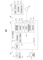
- FIG. 1 is a diagram illustrating a device configuration of an image processing system including a robot system including a robot control device according to an embodiment and a server as an external device.
- FIG. 2 is a functional block diagram of a robot control device and a server. 10 is a flowchart illustrating an example of a process for acquiring a detection result by a robot control device.
- FIG. 13 is a diagram illustrating another example of the device configuration of the image processing system.
- FIG. 2 is a functional block diagram of functions of a robot control device serving as an external device.
- FIG. 1 is a diagram showing the device configuration of an image processing system 200 including a robot system 100 equipped with a robot control device 20 according to one embodiment, and a server 90 as an external device.
- the image processing system 200 is configured as a system in which the server 90 as an external device is connected to the robot system 100 equipped with the robot control device 20 via a network 80.
- the robot system 100 comprises a robot controller 20, a robot 10 controlled by the robot controller 20, a teaching operation panel 30 connected to the robot controller 20, and a visual sensor 40 connected to the robot controller 20.
- the robot system 100 is configured to perform image processing such as detection and judgment of an object based on an image captured by the visual sensor 40, and to have the robot 10 handle the object based on these results.
- the robot controller 20 has a function to control the visual sensor 40 to obtain an image of the object, and a function to output image data based on the captured image to a server 90 to perform image processing such as detection and obtain the results (detection results, etc.).
- the robot controller 20 controls the operation of the robot 10 according to an operating program loaded into the robot controller 20 or commands from the teaching operation panel 30.
- the robot controller 20 may also have a function of performing image processing such as detection of images captured by the visual sensor.
- the robot controller 20 may have a hardware configuration as a general computer having a processor 21, memory (ROM, RAM, non-volatile memory, etc.), storage unit 22, operation unit, input/output interface, network interface, etc. (see FIG. 2).
- the teaching operation panel 30 is used as an operation terminal for teaching (creating a program) the operation program of the robot 10, teaching related to image capture and image processing by the visual sensor 40, displaying images captured by the visual sensor 40, and performing various other settings.
- An information processing device such as a tablet terminal may be used as the teaching operation panel 30.
- the teaching operation panel 30 may have a hardware configuration as a general computer having a processor, memory (ROM, RAM, non-volatile memory, etc.), storage device, operation unit, display unit 31, input/output interface, network interface, etc.
- the robot 10 is a vertical articulated robot, but other types of robots such as parallel link robots and dual-arm robots may be used depending on the purpose of the work.
- the robot 10 can perform the desired work using an end effector attached to the wrist.
- the robot 10 is equipped with a hand (not shown) and can perform operations such as picking up an object based on the detection position of the object detected from an image captured by the visual sensor 40.
- Objects to be detected by the visual sensor 40 i.e., objects to be handled by the robot 10) can be a variety of objects, such as machine parts, food, medicines, etc.
- the object may also be a three-dimensional object such as a box.
- the visual sensor 40 may be a two-dimensional camera that captures two-dimensional images, or a three-dimensional camera that can obtain distance images.
- a TOF (Time of Flight) camera that captures distance images using the time-of-flight method, or a stereo camera including two cameras, etc.
- the visual sensor 40 may be fixedly installed in the working space as shown in FIG. 1, or may be mounted on a predetermined movable part of the robot 10 (such as the tip of the arm). The visual sensor 40 has been calibrated, and the position of the visual sensor 40 in the working space is known to the robot control device 20.
- the robot control device 20 can determine the position detected on the image captured by the visual sensor 40 as a position on a coordinate system (such as a robot coordinate system) set in the working space.
- the calibration data (such as position information of the visual sensor 40) is stored in the memory unit 22 (see FIG. 2) of the robot control device 20.
- the server 90 can provide a function for performing image processing such as detection on image data sent from the robot control device 20.
- the server 90 may have a hardware configuration as a general computer having a processor, memory (ROM, RAM, non-volatile memory, etc.), storage device, operation unit, display unit, input/output interface, network interface, etc.
- FIG. 2 is a functional block diagram of the robot control device 20 and the server 90.
- the robot control device 20 includes an operation control unit 121, a visual sensor control unit 122, an image acquisition unit (first acquisition unit) 123, a preprocessing unit 124, an output unit 125, a detection unit 126, a detection result acquisition unit (second acquisition unit) 127, and a comparison and integration unit 128.
- These functional blocks may be realized by the processor 21 of the robot control device 20 executing software.
- FIG. 2 also illustrates a memory unit 22 provided in the robot control device 20.
- the memory unit 22 is, for example, a storage device consisting of a non-volatile memory or a hard disk drive.
- the memory unit 22 stores a robot program for controlling the robot 10, a program (detection program, etc.) for performing image processing such as workpiece detection based on an image captured by the visual sensor 40, calibration data, model data of the target object, various setting information, etc.
- the motion control unit 121 controls the motion of the robot 10 according to the robot program or according to commands from the teaching operation panel 30.
- the robot control device 20 is equipped with a servo control unit (not shown) that performs servo control on the servo motors of each axis of the robot 10 according to commands for each axis generated by the motion control unit 121.
- the visual sensor control unit 122 has the function of controlling the visual sensor 40.
- the visual sensor control unit 122 controls the imaging by the visual sensor 40 according to instructions written in the detection program.
- the image acquisition unit 123 has a function of acquiring an image captured by the visual sensor 40.
- the image captured by the visual sensor 40 is a two-dimensional image or a distance image.
- the pre-processing unit 124 performs pre-processing to efficiently perform image processing such as detection on the image captured by the visual sensor 40.
- the pre-processing unit 124 can perform pre-processing according to pre-specified instruction contents.
- the instruction contents may be, for example, contents input by an operator via the instruction operation panel 30.
- the pre-processing may include, for example, one or more of image reduction, background removal, and cropping.
- Image reduction is the process of reducing the size of a captured image to lower its resolution (number of pixels).
- Background removal is a process that removes background areas on the captured image where no object is located.
- the pre-processing unit 124 may detect the outline of the container on the image based on the model data of the container, and remove parts other than the container from the image.
- the pre-processing unit 124 may accept an operation by the worker to specify the area (outline) of the container on the captured image, and remove parts other than the specified container area from the image.
- the preprocessing unit 124 may, for example, treat areas in the distance image whose height is below a certain value (or above a certain value) as background and remove them from the image.
- the preprocessing unit 124 may treat areas in the image whose height is below a certain value as floor surface (background) and remove them from the image.
- Trimming can be achieved, for example, by an operator specifying an area on the captured image where no object is located, and removing the specified area from the captured image.
- the pre-processing unit 124 may be configured to accept an operation by the operator to specify such an unnecessary part on the captured image, and to perform processing to remove the unnecessary part from the captured image.
- This preprocessing can reduce the load on image processing such as detection and shorten the processing time. Furthermore, if the preprocessed image data is transferred to the server 90 for image processing, the transfer time of the image data can be shortened.
- the pre-processing unit 124 may have a function of providing a user interface for the operator to input the above-mentioned teaching contents.
- the user interface may be presented on the display unit 31 of the teaching operation panel 30. Input operations to the user interface may be accepted via the operation unit of the teaching operation panel 30.
- the pre-processing unit 124 provides the pre-processed image data to the output unit 125 and the detection unit 126.
- the pre-processing by the pre-processing unit 124 may include a process of dividing the captured image (image data) obtained from the visual sensor 40 into a plurality of regions.
- the pre-processing unit 124 divides the image data obtained from the visual sensor 40 into two regions, a first image portion and a second image portion
- the detection unit 126 executes a detection process on the first image portion
- the output unit 125 transmits the second image portion to the server 90 to execute a detection process on the second image portion.
- the detection result acquisition unit 127 acquires the detection result on the second image portion from the server 90.
- the robot control device 20 (comparison and integration unit 128) can integrate the detection result on the first image portion by the detection unit 126 and the detection result on the second image portion by the server 90 to obtain a final detection result.
- the output unit 125 outputs the image data that has been preprocessed by the preprocessing unit 124 to the server 90.
- the connection between the robot control device 20 and the server 90 may be a connection via a wired or wireless LAN (local area network), or a commercial network such as the Internet.
- the server 90 may provide a processing function based on so-called cloud computing.
- the output unit 125 sends the image data to the server 90 via the network 80, and causes the server 90 to execute detection processing on the image data.
- the output unit 125 is configured to have a function of transferring transmission data including, for example, image data and a request for detection processing to the server 90. In this case, the output unit 125 can transmit the transmission data to the server 90 at any timing when the image data is generated by the pre-processing unit 124.
- the detection unit 126 has a function of executing a detection process on the image data that has been subjected to preprocessing.
- the detection unit 126 detects an object by performing pattern matching between image features extracted from the image data and model data (model features) instructed by the operator.
- the image features are, for example, edge features.
- the detection unit 126 outputs the result of the detection process.
- the detection result includes, for example, information such as the time required for detection, the detected position and orientation of the object, the number of detections, the detection score, contrast, distortion, angle, and size.
- the detection score is an evaluation value as the degree of match of the pattern matching.
- the number of detections indicates the number of objects detected in one detection process.
- the contrast indicates the contrast of the outline of the object on the image against the background.
- the distortion indicates the degree of distortion of the object on the image relative to the work model.
- the angle indicates the deviation in the rotational direction of the object on the image relative to the work model.
- the size indicates the difference (ratio) between the size of the object on the image relative to the size of the work model.
- the detection unit 126 provides the information of the detection result to the comparison and integration unit 128.
- the server 90 comprises an image data receiving unit 191, a detection processing unit 192, and a detection result output unit 193.
- the image data receiving unit 191 receives image data from the output unit 125 of the robot control device 20.
- the image data receiving unit 191 is configured to be able to receive a transmission request for image data that arrives at any timing from the output unit 125 of the robot control device 20.
- the image data receiving unit 191 checks the transmission data (e.g., image data and a detection processing request) from the output unit 125, and provides the image data to the detection processing unit 192.
- the detection processing unit 192 executes detection processing on the received image data.
- Various data required for the detection processing such as a detection program and model data, are stored in advance in the server 90.
- the detection processing unit 192 has a function of performing detection by performing pattern matching between image features extracted from the image data and model data (model features).
- the detection results include information such as the time required for detection, the detected position and orientation of the object, the number of detections, the detection score, contrast, distortion, angle, size, etc.
- the detection result output unit 193 sends the detection result by the detection processing unit 192 to the robot control device 20.
- the detection result output unit 193 can transmit the detection result to the robot control device 20 at the timing when the detection result by the detection processing unit 192 is obtained.
- the detection result acquisition unit 127 of the robot control device 20 acquires the detection results from the detection result output unit 193 of the server 90.
- the detection result acquisition unit 127 is configured to be able to accept transmission data from the detection result output unit 193 that arrives at any timing.
- the detection result acquisition unit 127 provides the received detection results to the comparison and integration unit 128.
- the comparison and integration unit 128 has a function of obtaining a final detection result by at least comparing or integrating the detection result by the detection unit 126 in the robot control device 20 and the detection result by the detection processing unit 192 of the server 90.
- the function of determining the final detection result by the comparison and integration unit 128 includes a method of determining a type in which two detection results are compared and one of the detection results is selectively used, and a method of determining a type in which the two detection results are integrated and used.
- the comparison and integration unit 128 is configured to have, for example, one or more of the functions shown below.
- (F11) A function to adopt the earlier detection result of two detection results. This function is for shortening the overall operation time by selecting the detection result obtained first when the detection process is executed by the robot control device 20 and the server 90.
- the comparison and integration unit 128 may realize this function by starting detection by the detection unit 126 in the robot control device 20 and transmitting the preprocessed image data to the server 90, and then adopting the detection result obtained first.
- (F12) A function that adopts the detection result with the higher detection score between two detection results. In general, detection results that are false positives (misjudging that a non-target image feature is the target) tend to have low detection scores. Therefore, by adopting the detection result with the higher detection score, it is possible to adopt the correct detection result.
- a selection may be made based on a comparison using the detection position, the detection size, the detection distortion, or the detection angle.
- a reference value of the detection position may be stored in advance, and the two detection positions may be compared and the one closest to the reference value may be adopted (function (F13)).
- a statistical value (average value, mode value, etc.) obtained by performing detection a certain number of times in the robot system 100, or a design value of the placement position of the object may be used.
- the detection size a detection result whose detection size is closer to the size of the work model (closer to 100%) may be adopted (function (F14)).
- the detection distortion a detection result whose degree of detection distortion is smaller may be adopted (function (F15)).
- the detection angle a detection result whose deviation in the detection angle with respect to the work model is smaller may be adopted (function (F16)).
- This function is a determination method for obtaining a more appropriate detection result by integrating two detection results even in a situation where an object can only be detected by one of the detection processes. For example, assume that there are five objects to be detected (W1, W2, W3, W4, W5), and one detection process (first detection process) detects three objects (W1, W2, W3), while the other detection process (second detection process) detects four objects (W2, W3, W4, W5).
- the comparison and integration unit 128 determines the detection position information of (W1, W2, W3) as the result of the first detection process and the detection position information of (W2, W3, W4, W5) as the result of the second detection process, W2 and W3 are detected by both the first detection process and the second detection process.
- the first detection process is able to detect W1 that could not be detected in the second detection process.
- the second detection process was able to detect W4 and W5, which could not be detected by the first detection process. It is possible to grasp the difference between the positions of the two detection results.
- the comparison and integration unit 128 may determine that the same object has been detected when the difference in position between the two detection results is equal to or less than a predetermined threshold, and may determine that different objects have been detected when the difference in position exceeds a predetermined threshold. In the above example, the comparison and integration unit 128 can obtain a final detection result that the five objects (W1, W2, W3, W4, W5) have been correctly detected by integrating the detection results of the first detection process and the second detection process.
- (F22) A function that integrates the results of detections performed on different parts of image data. This function is effective when the pre-processing unit 124 executes a process of dividing the image data from the visual sensor 40 into a plurality of regions. For example, the pre-processing unit 124 divides the image data from the visual sensor 40 into two parts (a first image part and a second image part), the detection unit 126 of the robot control device 20 executes a detection process for the first image part, and the detection processing unit 192 of the server 90 executes a detection process for the second image part. In this case, the comparison and integration unit 128 can obtain a detection result for the entire image data from the visual sensor 40 by combining the respective detection results. This function makes it possible to distribute the load of image processing and shorten the overall time required for detection processing.
- the captured image from the visual sensor 40 is divided into two regions, and detection processing is performed on different partial images by two devices (the robot control device 20 and the server 90 as an external device). It is also possible to configure the captured image to be divided into three or more regions, and the detection processing for each partial image to be shared by three or more devices. For example, the detection processing for three or more partial images may be shared by the robot control device 20 and two or more external devices connected to the robot control device 20.
- the image can be divided by dividing the captured image evenly by the number of devices, or by setting the size of the partial images in proportion to the processing capacity of each of the multiple devices.
- the pre-processing unit 124 may have a function for automatically dividing the captured image evenly by the number of devices.
- the pre-processing unit 124 may be configured to receive information on the processing capacity of each device from the operator, and based on that information, divide the captured image into partial images with sizes proportional to the processing capacity of each of the multiple devices.
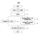
- FIG. 3 is a flowchart showing an example of a process for acquiring the detection results by the robot control device 20 (hereinafter also referred to as the detection result acquisition process). This process is executed under the control of the processor 21.
- the visual sensor control unit 122 the visual sensor 40 captures an image of an object (step S1).
- the pre-processing unit 124 performs pre-processing on the captured image in accordance with the specified instruction content (step S2). As described above, the pre-processing can include image reduction, background removal, cropping, image division, etc.
- the detection unit 126 executes detection processing on the preprocessed image data (step S3).
- the output unit 125 transmits the preprocessed image data to an external device (server 90) and requests detection processing (step S4).
- the detection result acquisition unit 127 receives the detection result from the external device (server 90) (step S5).
- the comparison and integration unit 128 obtains a final detection result by at least comparing or integrating the detection result by the detection unit 126 in the robot control device 20 and the detection result by the detection processing unit 192 of the server 90 (step S6).
- the comparison or integration here may include one or more of the above-mentioned functions (F11) to (F16), (F21), and (F22).
- the position information of the object obtained as a detection result in this way is provided to the operation control unit 121 and is used for position correction in controlling the robot 10.
- the robot control device 20 is configured to have an interface for outputting image data of an image captured by the visual sensor 40 connected to the robot control device 20 to an external device.
- the robot control device 20 can output image data to an external device to cause the external device to perform a detection process.
- the robot control device 20 also has a function as an interface for receiving information on the overall result of the detection process performed by the external device (including the time required for detection, the detected position and orientation of the object, the number of detections, the detection score, contrast, distortion, angle, size, etc.).
- the computational resources of the robot control device 20 are restricted by the need to prioritize control of the robot.
- the robot control device 20 having the above configuration makes it possible for the robot control device 20 connected to the visual sensor to efficiently realize the execution of the detection process by entrusting it to an external device, thereby improving the efficiency of the entire work by the robot system. Therefore, according to the above configuration, the robot control device 20 can perform the detection process even in a situation where the detection unit 126 is subject to operational restrictions. Furthermore, according to the above configuration, the robot control device 20 can perform the detection process even if it does not have the function of the detection unit 126.
- the robot control device 20 can offload image processing such as detection, which generally involves a significant computational load, to an external device such as a server that has advanced computational resources (processor processing power, memory performance, etc.), thereby improving overall processing efficiency.
- the robot control device 20 is configured to be able to transfer image data after preprocessing, including image reduction, to the external device, thereby reducing the transfer time to the external device and improving overall processing efficiency.
- the robot control device 20 itself is configured to be able to execute the detection process, so that even if a delay or interruption occurs in communication with an external device, work in the robot system is not interrupted. Furthermore, the robot control device 20 can obtain a final detection result by comparing or integrating the detection result by the robot control device 20 with the detection result by the external device. In this case, the robot control device 20 can compare the detection result by the robot control device 20 with the detection result by the external device and select and use the detection result with higher accuracy. Furthermore, the robot control device 20 can further enrich the information as a detection result by integrating the detection result by the robot control device 20 with the detection result by the external device so that they complement each other.
- the external device may be any of a variety of devices with image processing capabilities.
- a dedicated image processing device or a general-purpose personal computer may be used as the external device.
- the robot controller 20 sends the preprocessed image data to the multiple external devices and causes each external device to execute detection processing. Then, the robot controller 20 can compare or integrate the detection results of the robot controller 20 with the detection results of the multiple external devices to obtain a final detection result. For example, the robot controller 20 may determine, from among the multiple detection results, the one that satisfies any of the following selection criteria (r1) to (r6) as the final detection result.
- the detection time is the shortest.
- the detected position is closest to the reference value.
- the detected size is closest to the model data.
- the degree of detection distortion is the smallest.
- the deviation of the detected angle is the smallest.
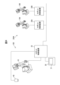
- FIG. 4 is a diagram showing an example of a system configuration in such a case.
- the image processing system 200A is configured such that the robot control devices 20A and 20B are connected to the above-mentioned robot system 100 via a network in the factory.
- the robot control devices 20A and 20B control the robots 10A and 10B, respectively.
- the robot control device 20 can use the robot control devices 20A and 20B as external devices.
- FIG. 5 is a functional block diagram of functions related to image processing among the functions possessed by each of the robot controllers 20A and 20B.
- each of the robot controllers 20A and 20B has an image data receiving unit 191A, a detection processing unit 192A, and a detection result output unit 193A.
- the image data receiving unit 191A has a function of receiving image data from the output unit 125 of the robot controller 20.
- the detection processing unit 192A executes detection processing on the received image data.
- the detection result output unit 193A has a function of sending the detection result to the robot controller 20.
- the output unit 125 of the robot controller 20 sends the preprocessed image data to the robot controllers 20A and 20B, causing each of the robot controllers 20A and 20B to execute detection processing on the image data.
- the detection result acquisition unit 127 of the robot controller 20 then receives the detection results from each of the robot controllers 20A and 20B.
- the comparison and integration unit 128 of the robot controller 20 can obtain the final detection result by comparing or integrating the detection result of the robot controller 20A with the detection results by the robot controllers 20A and 20B as described above.
- the comparison or integration function of the comparison and integration unit 128 may include functions based on one or more of the above-mentioned functions (F11) to (F16), (F21), and (F22).
- the comparison and integration unit 128 can select and use the most accurate detection result from the detection results of the robot control devices 20, 20A, and 20B by using any of the above-mentioned selection criteria (r1) to (r6).
- the robot control device 20 can also integrate the detection results of the robot control devices 20, 20A, and 20B so that they complement each other.
- FIG. 4 shows an example in which there are two robot control devices as external devices, there may be one robot control device as external devices, or three or more robot control devices as external devices.
- each embodiment makes it possible to efficiently and reliably perform image processing such as detection while preventing the device configuration in the robot system from becoming too complicated.
- the robot control device 20 (output unit 125) is configured to output preprocessed image data to an external device (server 90) to execute detection processing, but the robot control device 20 (output unit 125) may also send image data that has not been preprocessed (i.e., image data captured by the visual sensor 40) directly to an external device to execute detection processing. Even in this case, the advantages of the comparison or integration by the comparison and integration unit 128 described above can be realized.
- the functional allocation in the functional block diagram shown in FIG. 2 is an example, and various modified functional arrangements can be configured.
- the function of the teaching operation panel 30 can be defined as being integrated with the robot control device 20.
- FIG. 2 there can also be a configuration example in which some of the functions arranged in the robot control device 20 are arranged within the teaching operation panel 30.
- the configuration of the above-described embodiment can be applied not only to robot control devices, but also as a function of a control device that controls various industrial machines.
- the functional blocks of the robot control device 20 shown in FIG. 2 may be realized by one or more processors of the robot control device 20 executing various software stored in a storage device, or may be realized by a hardware-based configuration such as an ASIC (Application Specific Integrated Circuit).
- ASIC Application Specific Integrated Circuit
- the programs that execute various processes such as the detection result acquisition process in the above-mentioned embodiments can be recorded on various computer-readable recording media (e.g., semiconductor memory such as ROM, EEPROM, flash memory, magnetic recording media, and optical disks such as CD-ROM and DVD-ROM).
- semiconductor memory such as ROM, EEPROM, flash memory, magnetic recording media, and optical disks such as CD-ROM and DVD-ROM.
- a robot control device (20) comprising: (Appendix 2) A detection unit (126) that performs a detection process based on the preprocessed image data;
- the robot control device (20) described in Appendix 1 further includes a comparison and integration unit (128) that obtains a final detection result by at least one of comparing and integrating the detection results by the detection unit and the detection results by the one or more external devices.
- Appendix 4 The robot control device (20) described in Appendix 3, wherein the comparison and integration unit (128) selects as the final detection result, from among the detection results of the detection unit (126) or the detection results of the one or more external devices, a detection result that satisfies any one of the selection criteria of the shortest detection time, the highest detection score, a detection position that is closest to a predetermined reference value, a detection size that is closest to model data, a smallest degree of detection distortion, or a smallest deviation in detection angle.
- the pre-processing includes dividing the image data into a plurality of parts;
- (Appendix 7) The robot control device (20) of any one of appendixes 1 to 6, wherein the pre-processing includes at least one of reducing the image data, removing a background, or cropping the image data.
- (Appendix 8) The robot control device (20) according to any one of appendices 1 to 7, wherein the pre-processing unit (124) executes the pre-processing in accordance with teaching contents specified by an operator.
- (Appendix 9) A robot control device (20) described in any one of appendix 2 to 6, comprising an operation control unit (121) that controls the robot based on the final detection result.
- (Appendix 10) A robot control device (20) according to claim 1, comprising an operation control unit (121) that controls the robot based on the detection result.
- the one or more external devices (90) one or more servers having more advanced computing resources than the robot controller (20); one or more dedicated image processing devices; one or more computers, or 11.
- An image processing system (200) comprising:
Landscapes
- Engineering & Computer Science (AREA)
- Robotics (AREA)
- Mechanical Engineering (AREA)
- Computer Vision & Pattern Recognition (AREA)
- Physics & Mathematics (AREA)
- General Physics & Mathematics (AREA)
- Theoretical Computer Science (AREA)
- Manipulator (AREA)
- Image Analysis (AREA)
Abstract
Description
(F11)2つの検出結果のうち検出時間の早い方の検出結果を採用する機能。
この機能は、ロボット制御装置20とサーバ90とで検出処理を実行した場合に先に得られた検出結果を選択することで全体的な作業時間を短縮するための機能である。例えば、比較統合部128は、ロボット制御装置20において検出部126で検出を開始すると共に、前処理後の画像データをサーバ90側に送信した後、先に得られた方の検出結果を採用する形でこの機能を実現してもよい。
(F12)2つの検出結果のうち検出スコアが高い方の検出結果を採用する機能。
一般に、誤検出(対象物でない画像特徴を対象物と誤判定すること)となる検出結果は検出スコアが低いという傾向がみられる。したがって、検出スコアが高い方の検出結果を採用することで適正な検出結果を採用し得る。
(F21)2つの検出結果が互いに補完し合うように2つの検出結果を統合する機能。
本機能は、一方の検出処理のみでしか検出できなかった対象物があるような状況であっても2つの検出結果を統合することでより適正な検出結果を得る決定方法である。例えば、検出すべき対象物が5つある(W1、W2、W3、W4、W5)状況で、一方の検出処理(第1検出処理)では3つの対象物(W1、W2、W3)が検出でき、他方の検出処理(第2検出処理)では4つの対象物(W2、W3、W4、W5)が検出できているとする。比較統合部128は、第1検出処理の結果としての(W1、W2、W3)の検出位置情報と、第2検出処理の結果としての(W2、W3、W4、W5)の検出位置情報とから、
・W2及びW3は、第1検出処理及び第2検出処理の双方で検出できていること、
・第1検出処理では第2検出処理で検出できなかったW1を検出できていること、
・第2検出処理では第1検出処理では検出できなかったW4、W5を検出できていること、
を把握することができる。なお、この場合、比較統合部128は、2つの検出結果における位置の相違が所定の閾値以下である場合に同じ対象物を検出していると判断し、位置の相違が所定の閾値を超える場合に異なる対象物を検出していると判断するようにしてもよい。上記例の場合、比較統合部128は、第1検出処理の検出結果と第2検出処理の検出結果とを統合することで、5つの対象物(W1、W2、W3、W4、W5)を正しく検出したという最終的な検出結果を得ることができる。
この機能は、前処理部124が、視覚センサ40からの画像データを複数の領域に分割する処理を実行する場合に有効な機能である。例えば、前処理部124が、視覚センサ40による画像データを2つの部分(第1画像部分及び第2画像部分)に分割し、ロボット制御装置20の検出部126が第1画像部分について検出処理を実行し、サーバ90の検出処理部192が第2画像部分について検出処理を実行する。この場合、比較統合部128は、それぞれの検出結果をまとめることで、視覚センサ40からの画像データ全体に対する検出結果を得ることができる。この機能により、画像処理の負荷を分散し、検出処理に要する全体的な時間を短縮することが可能となる。
(r1)検出時間が最も短い。
(r2)検出スコアが最も高い。
(r3)検出位置が基準値に最も近い。
(r4)検出サイズがモデルデータに最も近い。
(r5)検出歪みの度合いが最も小さい。
(r6)検出角度のずれが最も小さい。
(付記1)
画像データを取得可能な第1取得部(123)と、
前記画像データを前処理する前処理部(124)と、
前記画像データ又は前記前処理された画像データを1つ以上の外部機器(90)に出力可能な出力部(125)と、
前記画像データ又は前記前処理された画像データに対する前記1つ以上の外部機器による検出処理の実行結果としての検出結果を取得する第2取得部(127)と、
を備えるロボット制御装置(20)。
(付記2)
前記前処理された画像データに基づいて検出処理を実行する検出部(126)と、
前記検出部による検出結果と前記1つ以上の外部機器による検出結果について、比較又は統合の少なくともいずれかを行うことにより最終的な検出結果を得る比較統合部(128)とを更に備える、付記1に記載のロボット制御装置(20)。
(付記3)
前記比較統合部(128)は、検出結果としての検出スコア、検出時間、検出位置、検出サイズ、検出歪み、又は検出角度のうち少なくともいずれかについて、前記検出部(126)の検出結果と前記1つ以上の外部機器(90)の検出結果とを比較することに基づき前記最終的な検出結果を得る、付記2に記載のロボット制御装置(20)。
(付記4)
前記比較統合部(128)は、前記検出部(126)の検出結果又は前記1つ以上の外部機器の検出結果のうち、前記検出時間が最も短い、前記検出スコアが最も高い、検出位置が所定の基準値に最も近い、検出サイズがモデルデータに最も近い、検出歪みの度合いが最も小さい、又は、検出角度のずれが最も小さい、のいずれかの選択基準を満たす検出結果を前記最終的な検出結果として選択する、付記3に記載のロボット制御装置(20)。
(付記5)
前記比較統合部(128)は、前記検出部(126)の検出結果と前記1つ以上の外部機器(90)の検出結果とを互いに補完し合うように統合することで前記最終的な検出結果を得る、付記2に記載のロボット制御装置(20)。
(付記6)
前記前処理は、前記画像データを複数の部分に分割する処理を含み、
前記比較統合部(128)は、前記検出部(126)と前記1つ以上の外部機器(90)とがそれぞれ前記分割された前記画像データの異なる部分について前記検出処理を実行した場合のそれぞれの検出結果を統合して前記最終的な検出結果を得る、付記2に記載のロボット制御装置(20)。
(付記7)
前記前処理は、前記画像データの縮小、背景の除去、又はトリミングの少なくともいずれかを含む、付記1から6のいずれか一項に記載のロボット制御装置(20)。
(付記8)
前記前処理部(124)は、作業者により指定された教示内容に従って前記前処理を実行する、付記1から7のいずれか一項に記載のロボット制御装置(20)。
(付記9)
前記最終的な検出結果に基づいてロボットを制御する動作制御部(121)を備える、付記2から6のいずれか一項に記載のロボット制御装置(20)。
(付記10)
前記検出結果に基づいてロボットを制御する動作制御部(121)を備える、付記1に記載のロボット制御装置(20)。
(付記11)
前記1つ以上の外部機器(90)は、
前記ロボット制御装置(20)より高度な計算リソースを有する1つ以上のサーバ、
1つ以上の画像処理専用機器、
1つ以上のコンピュータ、又は、
1つ以上の制御装置、のいずれかを含む、付記1から10のいずれか一項に記載のロボット制御装置(20)。
(付記12)
対象物を撮像し画像データを生成する視覚センサ(40)と、
検出処理を実行可能な1つ以上の外部機器(90)と、
前記視覚センサから前記画像データを取得可能な第1取得部(123)と、
前記画像データを前処理する前処理部(124)と、
前記画像データ又は前記前処理された画像データを前記1つ以上の外部機器に出力可能な出力部(125)と、
前記画像データ又は前記前処理された画像データに対する前記1つ以上の外部機器による検出処理の実行結果としての検出結果を取得する第2取得部(127)と、
を備える画像処理システム(200)。
20、20A、20B ロボット制御装置
21 プロセッサ
22 記憶部
30 教示操作盤
31 表示部
40 視覚センサ
80 ネットワーク
90 サーバ
100 ロボットシステム
121 動作制御部
122 視覚センサ制御部
123 画像取得部
124 前処理部
125 出力部
126 検出部
127 検出結果取得部
128 比較統合部
191 画像データ受付部
192 検出処理部
193 検出結果出力部
200、200A 画像処理システム
Claims (12)
- 画像データを取得可能な第1取得部と、
前記画像データを前処理する前処理部と、
前記画像データ又は前記前処理された画像データを1つ以上の外部機器に出力可能な出力部と、
前記画像データ又は前記前処理された画像データに対する前記1つ以上の外部機器による検出処理の実行結果としての検出結果を取得する第2取得部と、
を備えるロボット制御装置。 - 前記前処理された画像データに基づいて検出処理を実行する検出部と、
前記検出部による検出結果と前記1つ以上の外部機器による検出結果について、比較又は統合の少なくともいずれかを行うことにより最終的な検出結果を得る比較統合部とを更に備える、請求項1に記載のロボット制御装置。 - 前記比較統合部は、検出結果としての検出スコア、検出時間、検出位置、検出サイズ、検出歪み、又は検出角度のうち少なくともいずれかについて、前記検出部の検出結果と前記1つ以上の外部機器の検出結果とを比較することに基づき前記最終的な検出結果を得る、請求項2に記載のロボット制御装置。
- 前記比較統合部は、前記検出部の検出結果又は前記1つ以上の外部機器の検出結果のうち、
前記検出時間が最も短い、
前記検出スコアが最も高い、
前記検出位置が所定の基準値に最も近い、
前記検出サイズがモデルデータに最も近い、
前記検出歪みの度合いが最も小さい、又は、
前記検出角度のずれが最も小さい、
のいずれかの選択基準を満たす検出結果を前記最終的な検出結果として選択する、請求項3に記載のロボット制御装置。 - 前記比較統合部は、前記検出部の検出結果と前記1つ以上の外部機器の検出結果とを互いに補完し合うように統合することで前記最終的な検出結果を得る、請求項2に記載のロボット制御装置。
- 前記前処理は、前記画像データを複数の部分に分割する処理を含み、
前記比較統合部は、前記検出部と前記1つ以上の外部機器とがそれぞれ前記分割された前記画像データの異なる部分について前記検出処理を実行した場合のそれぞれの検出結果を統合して前記最終的な検出結果を得る、請求項2に記載のロボット制御装置。 - 前記前処理は、前記画像データの縮小、背景の除去、又はトリミングの少なくともいずれかを含む、請求項1から6のいずれか一項に記載のロボット制御装置。
- 前記前処理部は、作業者により指定された教示内容に従って前記前処理を実行する、請求項1から7のいずれか一項に記載のロボット制御装置。
- 前記最終的な検出結果に基づいてロボットを制御する動作制御部を備える、請求項2から6のいずれか一項に記載のロボット制御装置。
- 前記検出結果に基づいてロボットを制御する動作制御部を備える、請求項1に記載のロボット制御装置。
- 前記1つ以上の外部機器は、
前記ロボット制御装置より高度な計算リソースを有する1つ以上のサーバ、
1つ以上の画像処理専用機器、
1つ以上のコンピュータ、又は、
1つ以上の制御装置、のいずれかを含む、請求項1から10のいずれか一項に記載のロボット制御装置。 - 対象物を撮像し画像データを生成する視覚センサと、
検出処理を実行可能な1つ以上の外部機器と、
前記視覚センサから前記画像データを取得可能な第1取得部と、
前記画像データを前処理する前処理部と、
前記画像データ又は前記前処理された画像データを前記1つ以上の外部機器に出力可能な出力部と、
前記画像データ又は前記前処理された画像データに対する前記1つ以上の外部機器による検出処理の実行結果としての検出結果を取得する第2取得部と、
を備える画像処理システム。
Priority Applications (5)
| Application Number | Priority Date | Filing Date | Title |
|---|---|---|---|
| JP2025525530A JPWO2024252564A1 (ja) | 2023-06-07 | 2023-06-07 | |
| DE112023006096.7T DE112023006096T5 (de) | 2023-06-07 | 2023-06-07 | Robotersteuervorrichtung und Bildverarbeitungssystem |
| PCT/JP2023/021179 WO2024252564A1 (ja) | 2023-06-07 | 2023-06-07 | ロボット制御装置及び画像処理システム |
| CN202380098831.4A CN121219114A (zh) | 2023-06-07 | 2023-06-07 | 机器人控制装置以及图像处理系统 |
| TW113116785A TW202448647A (zh) | 2023-06-07 | 2024-05-07 | 機器人控制裝置及圖像處理系統 |
Applications Claiming Priority (1)
| Application Number | Priority Date | Filing Date | Title |
|---|---|---|---|
| PCT/JP2023/021179 WO2024252564A1 (ja) | 2023-06-07 | 2023-06-07 | ロボット制御装置及び画像処理システム |
Publications (1)
| Publication Number | Publication Date |
|---|---|
| WO2024252564A1 true WO2024252564A1 (ja) | 2024-12-12 |
Family
ID=93795332
Family Applications (1)
| Application Number | Title | Priority Date | Filing Date |
|---|---|---|---|
| PCT/JP2023/021179 Ceased WO2024252564A1 (ja) | 2023-06-07 | 2023-06-07 | ロボット制御装置及び画像処理システム |
Country Status (5)
| Country | Link |
|---|---|
| JP (1) | JPWO2024252564A1 (ja) |
| CN (1) | CN121219114A (ja) |
| DE (1) | DE112023006096T5 (ja) |
| TW (1) | TW202448647A (ja) |
| WO (1) | WO2024252564A1 (ja) |
Citations (2)
| Publication number | Priority date | Publication date | Assignee | Title |
|---|---|---|---|---|
| JP2018200680A (ja) * | 2017-05-25 | 2018-12-20 | キヤノン株式会社 | 撮影装置およびシステム |
| JP2020135623A (ja) * | 2019-02-22 | 2020-08-31 | ファナック株式会社 | 物体検出装置、制御装置及び物体検出用コンピュータプログラム |
Family Cites Families (1)
| Publication number | Priority date | Publication date | Assignee | Title |
|---|---|---|---|---|
| JP7148322B2 (ja) | 2018-08-23 | 2022-10-05 | ファナック株式会社 | 画像処理装置 |
-
2023
- 2023-06-07 CN CN202380098831.4A patent/CN121219114A/zh active Pending
- 2023-06-07 DE DE112023006096.7T patent/DE112023006096T5/de active Pending
- 2023-06-07 JP JP2025525530A patent/JPWO2024252564A1/ja active Pending
- 2023-06-07 WO PCT/JP2023/021179 patent/WO2024252564A1/ja not_active Ceased
-
2024
- 2024-05-07 TW TW113116785A patent/TW202448647A/zh unknown
Patent Citations (2)
| Publication number | Priority date | Publication date | Assignee | Title |
|---|---|---|---|---|
| JP2018200680A (ja) * | 2017-05-25 | 2018-12-20 | キヤノン株式会社 | 撮影装置およびシステム |
| JP2020135623A (ja) * | 2019-02-22 | 2020-08-31 | ファナック株式会社 | 物体検出装置、制御装置及び物体検出用コンピュータプログラム |
Also Published As
| Publication number | Publication date |
|---|---|
| CN121219114A (zh) | 2025-12-26 |
| JPWO2024252564A1 (ja) | 2024-12-12 |
| DE112023006096T5 (de) | 2026-02-26 |
| TW202448647A (zh) | 2024-12-16 |
Similar Documents
| Publication | Publication Date | Title |
|---|---|---|
| CN112276936B (zh) | 三维数据生成装置以及机器人控制系统 | |
| CN104842361B (zh) | 具有3d箱体定位功能的机器人系统 | |
| JP2012030320A (ja) | 作業システム、作業ロボット制御装置および作業プログラム | |
| US10825193B2 (en) | Position detecting apparatus and computer-readable recording medium | |
| JP6703812B2 (ja) | 3次元物体検査装置 | |
| JP2017042859A (ja) | ピッキングシステム、並びに、そのための処理装置、方法及びプログラム | |
| CN113284178B (zh) | 物体码垛方法、装置、计算设备及计算机存储介质 | |
| JP2012254518A (ja) | ロボット制御システム、ロボットシステム及びプログラム | |
| US9958856B2 (en) | Robot, robot control method and robot control program | |
| US20190317474A1 (en) | Numerical control system | |
| US11030767B2 (en) | Imaging apparatus and imaging system | |
| US20160005161A1 (en) | Robot system | |
| JP2020024484A (ja) | 制御システムおよび制御装置 | |
| CN113601510B (zh) | 基于双目视觉的机器人移动控制方法、装置、系统及设备 | |
| US20180215044A1 (en) | Image processing device, robot control device, and robot | |
| US10656097B2 (en) | Apparatus and method for generating operation program of inspection system | |
| CN114952832B (zh) | 基于单目六自由度物体姿态估计的机械臂拼装方法及装置 | |
| JP2014188617A (ja) | ロボット制御システム、ロボット、ロボット制御方法及びプログラム | |
| WO2020213194A1 (ja) | 表示制御システム、および、表示制御方法 | |
| JP2015003348A (ja) | ロボット制御システム、制御装置、ロボット、ロボット制御システムの制御方法及びロボットの制御方法 | |
| US12423843B2 (en) | Image processing device and machine tool | |
| JP2015160256A (ja) | ロボットシステム、処理装置及び制御方法 | |
| JP2020052032A (ja) | 撮像装置及び撮像システム | |
| WO2021210514A1 (ja) | ロボットの制御装置及び制御方法、ロボットシステム、ロボットの動作プログラムを生成する装置及び方法 | |
| CN121219114A (zh) | 机器人控制装置以及图像处理系统 |
Legal Events
| Date | Code | Title | Description |
|---|---|---|---|
| 121 | Ep: the epo has been informed by wipo that ep was designated in this application |
Ref document number: 23940666 Country of ref document: EP Kind code of ref document: A1 |
|
| ENP | Entry into the national phase |
Ref document number: 2025525530 Country of ref document: JP Kind code of ref document: A |
|
| WWE | Wipo information: entry into national phase |
Ref document number: 2025525530 Country of ref document: JP |
|
| WWE | Wipo information: entry into national phase |
Ref document number: 112023006096 Country of ref document: DE |
|
| WWP | Wipo information: published in national office |
Ref document number: 112023006096 Country of ref document: DE |