WO2024252553A1 - 量子化方法、量子化装置及びコンピュータープログラム - Google Patents
量子化方法、量子化装置及びコンピュータープログラム Download PDFInfo
- Publication number
- WO2024252553A1 WO2024252553A1 PCT/JP2023/021144 JP2023021144W WO2024252553A1 WO 2024252553 A1 WO2024252553 A1 WO 2024252553A1 JP 2023021144 W JP2023021144 W JP 2023021144W WO 2024252553 A1 WO2024252553 A1 WO 2024252553A1
- Authority
- WO
- WIPO (PCT)
- Prior art keywords
- quantization
- approximation error
- value
- class
- class boundary
- Prior art date
- Legal status (The legal status is an assumption and is not a legal conclusion. Google has not performed a legal analysis and makes no representation as to the accuracy of the status listed.)
- Ceased
Links
Images

Classifications
-
- H—ELECTRICITY
- H04—ELECTRIC COMMUNICATION TECHNIQUE
- H04N—PICTORIAL COMMUNICATION, e.g. TELEVISION
- H04N19/00—Methods or arrangements for coding, decoding, compressing or decompressing digital video signals
- H04N19/10—Methods or arrangements for coding, decoding, compressing or decompressing digital video signals using adaptive coding
- H04N19/102—Methods or arrangements for coding, decoding, compressing or decompressing digital video signals using adaptive coding characterised by the element, parameter or selection affected or controlled by the adaptive coding
- H04N19/124—Quantisation
Definitions
- the present invention relates to a quantization method, a quantization device, and computer program technology.
- L infinity constraint In high-quality digital signal processing, a quality assurance called the L infinity constraint (sometimes expressed as an infinity symbol written as a subscript to the lower right of the "L") is required. This constraint requires that the maximum absolute error be within an acceptable range.
- An example of an application is near-lossless coding of medical images.
- the L infinity constraint is realized by designing a corresponding quantizer.
- the present invention aims to provide technology that enables the provision of a more efficient quantizer.
- One aspect of the present invention is a quantization method in which, when a computer approximates a histogram of an input signal with a predetermined number of classes, the computer restricts class boundary candidates so as to keep the maximum absolute value of the quantization error below an allowable value, and stores in memory the quantization value that minimizes the approximation error and the minimum value of the approximation error at that time.
- the computer selects a class boundary for the next class, it calls up the stored minimum value from memory and uses it to calculate the approximation error in the class boundary selection at that time, thereby selecting a class boundary that minimizes the approximation error for the restricted class boundary candidates.
- One aspect of the present invention is a quantization device that includes a memory unit that stores a quantization value that minimizes the approximation error and the minimum value of the approximation error at that time when approximating a histogram of an input signal with a predetermined number of classes, and a control unit that restricts class boundary candidates so as to keep the maximum absolute value of the quantization error below an allowable value, stores the quantization value that minimizes the approximation error and the minimum value of the approximation error at that time in the memory unit, and when selecting a class boundary for the next class, retrieves the stored minimum value from memory and uses it to calculate the approximation error in the class boundary selection at that time, thereby selecting a class boundary that minimizes the approximation error for the restricted class boundary candidates.
- One aspect of the present invention is a computer program for causing a computer to function as a quantization device that includes a memory unit that stores a quantization value that minimizes the approximation error and the minimum value of the approximation error at that time when approximating a histogram of an input signal with a predetermined number of classes, and a control unit that restricts class boundary candidates so as to keep the maximum absolute value of the quantization error below an allowable value, stores the quantization value that minimizes the approximation error and the minimum value of the approximation error at that time in the memory unit, and when selecting a class boundary for the next class, retrieves the stored minimum value from memory and uses it to calculate the approximation error in the class boundary selection at that time, thereby selecting a class boundary that minimizes the approximation error for the restricted class boundary candidates.
- the present invention makes it possible to provide a more efficient quantizer.
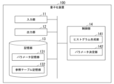
- FIG. 2 illustrates a specific example of a functional configuration of the quantization device 100.
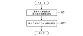
- 11 is a flowchart showing a specific example of a process flow of the quantization device 100.
- FIG. 2 is a diagram illustrating an outline of a hardware configuration example of an information processing device 90 applied to the present embodiment.
- K indicates the number of levels of the input signal to the quantizer (hereinafter referred to as the "number of input levels”).
- M indicates the number of levels of the output signal of the quantizer (hereinafter referred to as the "number of quantization levels”).
- the input to the quantizer is a histogram of the target signal.
- the quantizer to be formulated hereafter is an M-value quantizer defined by parameters ⁇ _m and L_m.
- ⁇ _m is the interval length of the m-th interval on the histogram (the m-th interval).
- L_m is the right end (upper end) of the m-th interval, and can be expressed as in the following equation (1). In the following description, L_m may also be called the class boundary of the m-th interval. Additionally, the possible values of L_m, which are the maximum values for each interval, are candidates for class boundaries.
- the m-th interval of the histogram [L_m-( ⁇ _m-1), L_m] will be referred to as the m-th bin (or the m-th quantization class).
- class refers to each interval of the histogram
- m-th quantization class refers to the m-th class of the histogram.
- the quantizer is designed to approximate the elements in the m-th bin with a representative value c_m and minimize the quantization error.
- the sum of squared errors shown in the following equation (2) is used as the quantization error e( ⁇ _m, L_m) in the m-th bin.
- c( ⁇ _m, L_m) is the quantization representative value of the m-th bin.
- the quantization representative value is set so that the maximum quantization error is equal to or smaller than the allowable value, as shown in the following formula (3).
- ⁇ is a parameter that controls the quality assurance of quantization.
- the above conditions indicate the L infinity constraint in quantizer design. Therefore, optimizing a quantizer that satisfies the L infinity constraint amounts to solving the following constrained minimization problem.
- L-infinity constraint quantizer A quantizer that satisfies the L-infinity constraint (hereinafter referred to as an "L-infinity constraint quantizer”) is designed by extending dynamic programming-based quantization (hereinafter referred to as "DP quantization"). Therefore, we clarify the constraints on the DP quantizer that are required to satisfy the L-infinity constraint.
- the quantization representative value must be calculated according to the range of ⁇ _m. Specifically, this is done according to the following formula (5).
- Dynamic programming is used to solve the constrained minimization problem shown in equation (4).
- the quantization error of each quantization bin is expressed by equation (2), and the quantization representative value is expressed by equation (5).
- the quantization representative value is constrained as described in equation (5).
- the quantization error e( ⁇ _m, L_m) of the Mth bin depends on the upper end L_m of the Mth bin and the factor prime ⁇ _m of the same bin.
- e( ⁇ _m, L_m) depends on L_m and ⁇ _m. Therefore, S_m[L_m] is expressed by the following recurrence formula using S_(m-1)[L_m- ⁇ _m].
- the index of the histogram element corresponding to the kth non-zero element in the histogram is represented as F[ ⁇ k].
- ⁇ _i is the number of non-zero elements in the i-th bin
- ⁇ L_i represents the upper end of the same bin.
- This error is stored in a look-up table represented by the following formula:
- ⁇ S_m[ ⁇ L_m] is equal to S_m[F[ ⁇ L_m]].
- ⁇ _m The key to introducing the L infinity constraint is to set an appropriate range for ⁇ _m. Specifically, the upper limit of ⁇ _m should be set to the following:
- ⁇ U_m in the above equation indicates that ⁇ U_m has two candidate values as its upper limit.
- ⁇ _l[m] is the upper limit of ⁇ _m.
- ⁇ [m] corresponds to L_m-m+1 in equation (7).
- the maximum distance between non-zero elements in each bin must be constrained. That maximum distance is at most about the extent of what can be expressed by the following equation.
- Fig. 1 is a diagram showing a specific example of the functional configuration of the quantization device 100.
- the quantization device 100 comprises an input unit 11, an output unit 12, a storage unit 13, and a control unit 14.
- the input unit 11 receives signals from other devices or networks, and inputs the signals to its own device (the quantization device 100).
- the signal input by the input unit 11 is referred to as the "input signal”.
- the output unit 12 outputs a signal (hereinafter referred to as the "converted signal”) obtained by quantizing the input signal with a predetermined number of classes by the control unit 14.
- the storage unit 13 is configured using a storage device such as a magnetic hard disk drive or a semiconductor storage device.
- the storage unit 13 stores information used by the control unit 14.
- the storage unit 13 functions as, for example, a parameter storage unit 131 and a reference table storage unit 132.
- the parameter storage unit 131 stores the quantization representative value and minimum approximation error determined by the control unit 14.
- the reference table storage unit 132 stores each value of the reference table generated by the control unit 14.
- the control unit 14 is configured using a processor such as a CPU (Central Processing Unit) and a memory.
- the control unit 14 functions as a histogram generating unit 141 and a parameter determining unit 142 by the processor executing a program. All or part of the functions of the control unit 14 may be realized using hardware such as an ASIC (Application Specific Integrated Circuit), a PLD (Programmable Logic Device), or an FPGA (Field Programmable Gate Array).
- the above program may be recorded on a computer-readable recording medium.
- Examples of computer-readable recording media include portable media such as flexible disks, optical magnetic disks, ROMs, CD-ROMs, and semiconductor storage devices (e.g., SSDs: Solid State Drives), and storage devices such as hard disks and semiconductor storage devices built into computer systems.
- portable media such as flexible disks, optical magnetic disks, ROMs, CD-ROMs, and semiconductor storage devices (e.g., SSDs: Solid State Drives), and storage devices such as hard disks and semiconductor storage devices built into computer systems.
- SSDs Solid State Drives
- the histogram generation unit 141 generates a histogram of the input signal (hereinafter referred to as the "input histogram").
- the parameter determination unit 142 determines a quantization value (quantization representative value) that minimizes the approximation error when approximating an input histogram with a predetermined number of classes, and the minimum value of the approximation error at that time (minimum approximation error). At this time, the parameter determination unit 142 determines the above two values by restricting candidates for class boundaries so as to keep the maximum absolute value of the quantization error below the allowable error. Specifically, the parameter determination unit 142 determines the quantization representative value by using the above-mentioned equation (5). The parameter determination unit 142 determines the minimum approximation error by using the above-mentioned equation (9). The parameter determination unit 142 records (stores) the determined quantization representative value and minimum approximation error in the memory unit 13.
- the parameter determination unit 142 determines the class boundary for each class.
- the parameter determination unit 142 reads out the minimum approximation error stored in the parameter storage unit 131 of the storage unit 13, and uses it to calculate the approximation error in selecting the class boundary at that time. By operating in this manner, the parameter determination unit 142 can determine the class boundary that minimizes the approximation error for the constrained class boundary candidates.
- the process of determining the class boundary is, in other words, the process of calculating the above-mentioned L_m.
- L_m the value of the right end (class boundary) of the previous quantization interval (previous class) is calculated using the following formula and recorded in the reference table of the storage unit 13.
- ⁇ _m indicates the optimal solution in formula (6).
- the parameter determination unit 142 traces the reference table backwards and identifies L_(M-2), which is the right end (class boundary) of the previous quantization interval (previous class) that corresponds to ⁇ _(M-1).
- the parameter determination unit 142 determines the class boundary for each class.
- the control unit 14 quantizes the input signal using the class boundary for each class determined in this way.
- FIG. 2 is a flowchart showing a specific example of the processing flow of the quantization device 100.
- the quantization device 100 determines a quantization representative value and a minimum approximation error (step S101). After that, the quantization device 100 identifies class boundaries for each class (step S102).
- the present invention configured in this way makes it possible to reduce bit depth conversion errors. It is possible to minimize quantization errors while satisfying constraints, and it is possible to reduce quantization errors in quantizers incorporated into digital signal processing.
- FIG. 3 is a diagram showing an outline of an example of the hardware configuration of an information processing device 90 applied to this embodiment.
- the information processing device 90 includes a processor 91, a main memory device 92, a communication interface 93, an auxiliary memory device 94, an input/output interface 95, and an internal bus 96.
- the processor 91, the main memory device 92, the communication interface 93, the auxiliary memory device 94, and the input/output interface 95 are connected to each other via the internal bus 96 so that they can communicate with each other.
- the information processing device 90 may be applied to, for example, a quantization device 100.
- the memory unit 13 may be configured using the main memory device 92 or the auxiliary memory device 94.
- the control unit 14 may be configured using the processor 91.
- the present invention is applicable to quantizers incorporated into digital signal processing.
- 100...quantization device 11...input unit, 12...output unit, 13...storage unit, 131...parameter storage unit, 132...reference table storage unit, 14...control unit, 141...histogram generation unit, 142...parameter determination unit, 90...information processing device, 91...processor, 92...main storage unit, 93...communication interface, 94...auxiliary storage unit, 95...input/output interface
Landscapes
- Engineering & Computer Science (AREA)
- Multimedia (AREA)
- Signal Processing (AREA)
- Compression, Expansion, Code Conversion, And Decoders (AREA)
Abstract
入力信号のヒストグラムに対して、所定のクラス数で、同ヒストグラムを近似する際、近似誤差を最小化する量子化値、および、そのときの近似誤差の最小値を記憶する記憶部と、量子化誤差の絶対値の最大値を許容値以下に抑えるように、クラス境界の候補を制限し、近似誤差を最小化する量子化値、および、そのときの近似誤差の最小値を前記記憶部に格納し、次のクラスでのクラス境界を選択する際、上記格納した最小値をメモリから呼び出し、その時点でのクラス境界選択における近似誤差の計算に用いることで、制約されたクラス境界の候補に対して近似誤差を最小化するクラス境界を選択する制御部と、を備える量子化装置。
Description
本発明は、量子化方法、量子化装置及びコンピュータープログラムの技術に関する。
近年,広ダイナミックレンジのデジタル信号処理への期待が高まっている。これを受けて、広ダイナミックレンジを有するデジタル信号に対する高いビット深度を用いた表現が検討されている。これにともない、取得する信号のビット深度を従来の8ビットから10ビット以上へと拡張した高ビット深度信号を取得可能なデバイスが登場してきている。一方、信号の高ビット深度化により、消費メモリが増大する。そのため、リソースに制約のある環境下で利用するためには、効率的な量子化手法が必要である。
高品質なデジタル信号処理用においては、L無限大(“L”の右下に無限大の記号を添え字として記して表すこともある。)制約と呼ばれる品質保証が要求される。本制約は、絶対値誤差の最大値が許容範囲に収まることを要請する制約である。応用先の例としては、医療画像に対するニアロスレス符号化があげられる。L無限大制約は、対応した量子化器を設計することで実現される。
Y. Bandoh, S. Takamura, and A. Shimizu, "Sparse DP quantization algorithm, " IEICE Trans.Fundamentals, vol. E102-A, no. 3, 2019.
S. Minewaki, M. Iwahashi, H. Kobayashi, T. Yoshida, and H. Kiya, "Near lossless coding of sparse histogram images based on zero-skip quantization, " Multimed Tools Appl., vol. 78, no. 1, pp. 27-45,Sept. 2017.
しかし、従来、L無限大制約を満たす量子化器の最適設計は解決されていない。例えば、動的計画法ベースの量子化(例えば非特許文献1参照)では、量子化誤差を最小化できるものの、L無限大制約を満たす保証はない。一方、ZSQと呼ばれる手法(例えば非特許文献2参照)は、L無限大制約を満たす量子化器を実現するものの、貪欲法ベースの方式であるため、設計された量子化器は、同制約条件下で量子化誤差を最小化できる保証がない。
上記事情に鑑み、本発明は、より効率的な量子化器の提供を可能する技術の提供を目的としている。
本発明の一態様は、コンピューターが、入力信号のヒストグラムに対して、所定のクラス数で、同ヒストグラムを近似する際、量子化誤差の絶対値の最大値を許容値以下に抑えるように、クラス境界の候補を制限し、近似誤差を最小化する量子化値、および、そのときの近似誤差の最小値をメモリに格納し、コンピューターが、次のクラスでのクラス境界を選択する際、上記格納した最小値をメモリから呼び出し、その時点でのクラス境界選択における近似誤差の計算に用いることで、制約されたクラス境界の候補に対して近似誤差を最小化するクラス境界を選択する、量子化方法である。
本発明の一態様は、入力信号のヒストグラムに対して、所定のクラス数で、同ヒストグラムを近似する際、近似誤差を最小化する量子化値、および、そのときの近似誤差の最小値を記憶する記憶部と、量子化誤差の絶対値の最大値を許容値以下に抑えるように、クラス境界の候補を制限し、近似誤差を最小化する量子化値、および、そのときの近似誤差の最小値を前記記憶部に格納し、次のクラスでのクラス境界を選択する際、上記格納した最小値をメモリから呼び出し、その時点でのクラス境界選択における近似誤差の計算に用いることで、制約されたクラス境界の候補に対して近似誤差を最小化するクラス境界を選択する制御部と、を備える、量子化装置である。
本発明の一態様は、入力信号のヒストグラムに対して、所定のクラス数で、同ヒストグラムを近似する際、近似誤差を最小化する量子化値、および、そのときの近似誤差の最小値を記憶する記憶部と、量子化誤差の絶対値の最大値を許容値以下に抑えるように、クラス境界の候補を制限し、近似誤差を最小化する量子化値、および、そのときの近似誤差の最小値を前記記憶部に格納し、次のクラスでのクラス境界を選択する際、上記格納した最小値をメモリから呼び出し、その時点でのクラス境界選択における近似誤差の計算に用いることで、制約されたクラス境界の候補に対して近似誤差を最小化するクラス境界を選択する制御部と、を備える量子化装置としてコンピューターを機能させるためのコンピュータープログラムである。
本発明により、より効率的な量子化器の提供が可能となる。
本発明の実施形態について、図面を参照して詳細に説明する。
以下、図又は式において変数等の上に付された記号(^:ハット、~:チルダ)は、変数の前に記載する。例えば、「^」が上に付されたcは、「^c」と表記する。以下、図又は式において変数又は記号の下付きの記号等と上付きの記号等とでは、それぞれ直前に下線「_」を記載したうえで、下付きの記号等を先に記載する。例えば、下付き「1」と上付き「*」とが付された変数Δは、「Δ_1_*」と表記する。例えば、下付き「i=0」と上付き「m」とが付された記号Σは、「Σ_i=0_m」と表記する。
以下、図又は式において変数等の上に付された記号(^:ハット、~:チルダ)は、変数の前に記載する。例えば、「^」が上に付されたcは、「^c」と表記する。以下、図又は式において変数又は記号の下付きの記号等と上付きの記号等とでは、それぞれ直前に下線「_」を記載したうえで、下付きの記号等を先に記載する。例えば、下付き「1」と上付き「*」とが付された変数Δは、「Δ_1_*」と表記する。例えば、下付き「i=0」と上付き「m」とが付された記号Σは、「Σ_i=0_m」と表記する。
以下の説明では、K-値の離散信号をM-値に変換する量子化器を定式化する。KとMとの関係は、M<Kである。Kは、量子化器の入力信号のレベル数(以下「入力レベル数」というう。)を示す。Mは、量子化器の出力信号のレベル数(以下「量子化レベル数」という。)を示す。量子化器への入力は、対象となる信号のヒストグラムである。ヒストグラムの第k番目の要素をH[k](k=0,・・・,K-1)とする。以降で定式化する量子化器は、パラメータΔ_m及びL_mで定義されるM-値の量子化器である。Δ_mは、m番目のヒストグラム上の区間(第m区間)の区間長である。L_mは第m区間の右端(上端)であり、以下の式(1)のように表せる。なお、以下の説明では、L_mのことを第m区間のクラス境界と呼ぶこともある。また、各区間の最大値であるL_mの取りうる値が、クラス境界の候補となる。

以降、ヒストグラムのm番目の区間[L_m-(Δ_m-1),L_m]を第mビン(又は第m量子化クラス)と呼ぶ。このように、以下の説明で「クラス」とは、ヒストグラムの各区間を示し、第m量子化クラス(又は単に「第mクラス」ともいう)はヒストグラムのm番目のクラスを指す。量子化器は、第mビン内の要素を代表値c_mで近似し、量子化誤差を最小化するように設計される。第mビン内の量子化誤差e(Δ_m,L_m)として、以下に示す式(2)のような二乗誤差和を用いる。

ここで、c(Δ_m,L_m)は、第mビンの量子化代表値である。量子化代表値は、以下に示す式(3)のように、最大量子化誤差が許容値以下になるように設定される。

ここでδは、量子化の品質保証を制御するパラメータである。上述した条件は、量子化器設計でのL無限大制約を示している。従って、L無限大制約を満たす量子化器の最適化は、以下の制約条件付き最小化問題を求解することになる。

[動的計画法に基づく量子化器設計]
L無限大制約を満たす量子化器(以下「L無限大制約量子化器」という。)の設計を動的計画法ベースの量子化(以下「DP量子化」という。)を拡張する形で行う。そこで、L無限大制約を満たすために必要となるDP量子化器に対する制約を明らかにする。
L無限大制約を満たす量子化器(以下「L無限大制約量子化器」という。)の設計を動的計画法ベースの量子化(以下「DP量子化」という。)を拡張する形で行う。そこで、L無限大制約を満たすために必要となるDP量子化器に対する制約を明らかにする。
DP量子化器に対する制約には、2つのポイントがある。第一のポイントは、Δ_mの制約として、各Δ_m(m=0,・・・,M-1)は、2δ+1以下に設定する必要があることである。第二のポイントは、Δ_mの範囲に応じて、量子化代表値を計算する必要があることである。具体的には、以下に示す式(5)による。
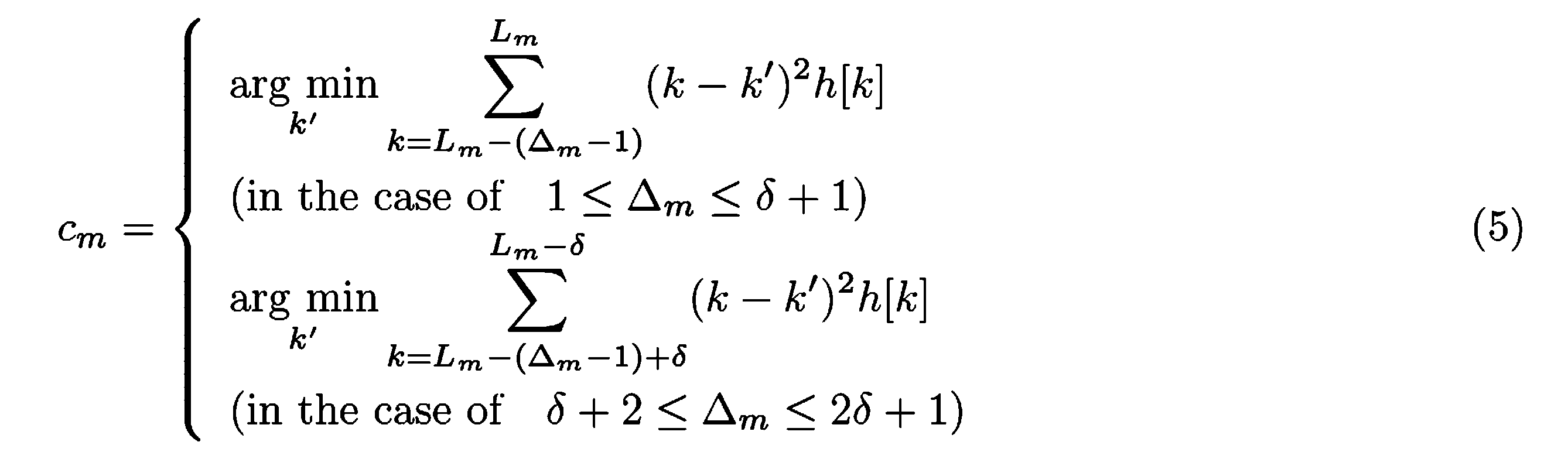
式(4)に示す制約条件付きの最小化問題を解くために動的計画法を用いる。各量子化ビンの量子化誤差は式(2)で表されており、量子化代表値は式(5)で表されている。量子化代表値は式(5)に記載されるように制約される。第Mビンの量子化誤差e(Δ_m,L_m)は、第Mビンの上端L_m、同ビンの要数素Δ_mに依存する。
したがって、式(4)で表される最適化問題の求解として動的計画法に基づくアプローチをとる。各L_m(m=0,・・・,M-1)の量子化誤差の最小値は、以下の式として表される。

各L_m(m=0,・・・,M-1)の量子化誤差の最小値として、S_m[L_m]を定義する。ここで、ヒストグラムh[k](k=0,・・・,K-1)の区間[0,L_m]は、m+1 ビンに分割されている。e(Δ_m,L_m)は、L_m、Δ_mに依存している。そのため、S_m[L_m]は、S_(m-1)[L_m-Δ_m]を用いて、以下の漸化式により表される。

ここで、m及びL_mはそれぞれ以下のように表される。
m=1,・・・,M-1
L_m=m,・・・,K-(M-m)
また、U_mは、Δ_mの上限として、次式により定める。
m=1,・・・,M-1
L_m=m,・・・,K-(M-m)
また、U_mは、Δ_mの上限として、次式により定める。

式(6)によれば、最良パラメータはΔ_m=1,・・・,U_mの範囲において選択される。前述の通り、この範囲の制約は、L無限大制約を満たすために課せられている。m=1、m=M-1において、各々式(6)を用いて、式(4)の最小化問題は以下のように表せる。

[疎性を考慮した拡張]
上述の量子化器設計を量子化対象信号の疎性を考慮した形で拡張する。ここでいう疎性とは、ヒストグラム内の要素として、多くのゼロ要素が含まれることを指す。以降、ヒストグラム内のゼロ要素をゼロ頻度値と呼ぶ。ゼロ頻度値を適切に考慮することにより、動的計画法ベースのL無限大制約量子化(DP量子化)の計算量を低減する。
上述の量子化器設計を量子化対象信号の疎性を考慮した形で拡張する。ここでいう疎性とは、ヒストグラム内の要素として、多くのゼロ要素が含まれることを指す。以降、ヒストグラム内のゼロ要素をゼロ頻度値と呼ぶ。ゼロ頻度値を適切に考慮することにより、動的計画法ベースのL無限大制約量子化(DP量子化)の計算量を低減する。
以下では、ヒストグラム内の第k番目の非ゼロ要素に対応するヒストグラムの要素のインデックスをF[~k]として表す。ヒストグラム内の区間[0,F[~L_m]]をm+1個のビンに分割することを考える。区間[0,F[~L_m]]のうち、以下の式で表される部分区間は、第i番目のビンである。

上記式において、~Δ_iは第i番目のビンの非ゼロ要素数であり、~L_iは同ビンの上端を表す。式(5)の量子化代表値で第i番目のビンを近似したことによる量子化誤差を以下のような式で表す。

この誤差は、以下の式で表される参照テーブルに格納される。

また、量子化誤差和は以下の式で表される。

上記式の最小値は、以下の参照テーブルに格納される。

なお、~S_m[~L_m]は、S_m[F[~L_m]]に等しい。また、~E[~Δ_m,~L_m]は、~Δ_m及び~L_mに依存する。そのため、~S_m[~L_m]に格納すべき値は、~S_(m-1)[~L_m-~Δ_m]を用いて、次式により計算される。なお、m=1,・・・,M-1である。

上記の定式化は、式(5)の量子化代表値および非ゼロ要素に関する制約を導くが、式(6)と同様に、漸化式(9)を得ることが出来る。したがって、漸化式(9)を用いることで、~S_m[~L_m]の計算は、最適パラメータ~Δ_mの選択に帰着される。
L無限大制約を導入するためのポイントは、~Δ_mの適切な範囲を設定することである。具体的には、~Δ_mの上限を以下とすることである。

式(7)におけるU_mと対比して、上式における~U_mを説明すると、上式は~U_mが、その上限として、二つの候補値を持つことを表している。まず、Ψ_l[m]は~Δ_mの上限である。Ψ[m]は式(7)のL_m-m+1に対応している。L無限大制約を満たすためには、各ビンの非ゼロ要素間の最大距離を制約しなければならない。その最大距離は、高々、以下の式で表される程度である。

この値は、式(7)の2δ+1に対応している。
次に、上述した方法により、入力信号のヒストグラムに対して所定のクラス数で複数のクラスに分ける処理を行う量子化装置100の機能構成の具体例について説明する。図1は、量子化装置100の機能構成の具体例を示す図である。量子化装置100は、入力部11、出力部12、記憶部13及び制御部14を備える。入力部11は、他の装置やネットワークから信号を受け付け、信号を自装置(量子化装置100)に入力する。入力部11によって入力された信号を「入力信号」という。出力部12は、制御部14によって入力信号が所定数のクラスで量子化された信号(以下「変換後信号」という。)を出力する。
記憶部13は、磁気ハードディスク装置や半導体記憶装置等の記憶装置を用いて構成される。記憶部13は、制御部14によって使用される情報を記憶する。記憶部13は、例えばパラメータ記憶部131及び参照テーブル記憶部132として機能する。パラメータ記憶部131は、制御部14によって決定される量子化代表値及び最小近似誤差を記憶する。参照テーブル記憶部132は、制御部14によって生成される参照テーブルの各値を記憶する。
制御部14は、CPU(Central Processing Unit)等のプロセッサーとメモリとを用いて構成される。制御部14は、プロセッサーがプログラムを実行することによって、ヒストグラム生成部141及びパラメータ決定部142として機能する。なお、制御部14の各機能の全て又は一部は、ASIC(Application Specific Integrated Circuit)やPLD(Programmable Logic Device)やFPGA(Field Programmable Gate Array)等のハードウェアを用いて実現されても良い。上記のプログラムは、コンピューター読み取り可能な記録媒体に記録されても良い。コンピューター読み取り可能な記録媒体とは、例えばフレキシブルディスク、光磁気ディスク、ROM、CD-ROM、半導体記憶装置(例えばSSD:Solid State Drive)等の可搬媒体、コンピューターシステムに内蔵されるハードディスクや半導体記憶装置等の記憶装置である。上記のプログラムは、電気通信回線を介して送信されてもよい。
ヒストグラム生成部141は、入力信号のヒストグラム(以下「入力ヒストグラム」という。)を生成する。
パラメータ決定部142は、入力ヒストグラムを予め定められた所定のクラス数で近似する際の近似誤差を最小化する量子化値(量子化代表値)と、そのときの近似誤差の最小値(最小近似誤差)と、を決定する。このとき、パラメータ決定部142は、量子化誤差の絶対値の最大値を許容誤差以下に抑えるように、クラス境界の候補を制限して上記2つの値を決定する。具体的には、パラメータ決定部142は、上述した式(5)を用いることによって、量子化代表値を決定する。パラメータ決定部142は、上述した式(9)を用いることによって、最小近似誤差を決定する。パラメータ決定部142は、決定された量子化代表値及び最小近似誤差を記憶部13に記録(格納)する。
次に、パラメータ決定部142は、各クラスでのクラス境界を決定する。このとき、パラメータ決定部142は、記憶部13のパラメータ記憶部131に格納されている最小近似誤差を読み出し、その時点でのクラス境界の選択における近似誤差の計算に用いる。このようにパラメータ決定部142が動作することによって、制約されたクラス境界の候補に対して近似誤差を最小化するクラス境界を決定することができる。
パラメータ決定部142が各クラスでのクラス境界を決定する処理の具体例について説明する。なお、クラス境界を決定する処理は、言い換えれば上述したL_mを算出する処理である。L_mに対して、一つ前の量子化区間(一つ前のクラス)の右端(クラス境界)の値を以下の式で算出して記憶部13の参照テーブルに記録しておく。なお、以下の式において、Δ_mは式(6)における最適解を示す。
L_m-Δ_m
L_m-Δ_m
パラメータ決定部142は、この処理をm=0からm=M-1まで繰り返し実行して参照テーブルに値を記録する。m=M-1の処理として、式(8)で得られたΔ_(M-1)の最適解が求まると、パラメータ決定部142は、参照テーブルを逆にたどり、Δ_(M-1)に対応する一つ前の量子化区間(一つ前のクラス)の右端(クラス境界)であるL_(M-2)を同定する。パラメータ決定部142は、この処理をm=M-2からm=0まで繰り返し実行することで、L_(M-3)からL_1の値をそれぞれ同定する。このような処理の実行によって、パラメータ決定部142が各クラスでのクラス境界を決定する。制御部14は、このように決定された各クラスのクラス境界を用いて入力信号を量子化する。
図2は、量子化装置100の処理の流れの具体例を示すフローチャートである。まず、量子化装置100は、量子化代表値及び最小近似誤差を決定する(ステップS101)。その後、量子化装置100は、各クラスのクラス境界を同定する(ステップS102)。
このように構成された本発明により、ビット深度変換誤差を低減することが可能となる。制約条件を満した上で、量子化誤差を最小化することが可能となり、デジタル信号処理に組み込まれる量子化器における量子化誤差の低減が可能となる。
図3は、本実施形態に適用される情報処理装置90のハードウェア構成例の概略を示す図である。情報処理装置90は、プロセッサー91、主記憶装置92、通信インターフェース93、補助記憶装置94、入出力インターフェース95及び内部バス96を備える。プロセッサー91、主記憶装置92、通信インターフェース93、補助記憶装置94及び入出力インターフェース95は、内部バス96を介して互いに通信可能に接続される。情報処理装置90は、例えば量子化装置100に適用されてもよい。この場合、例えば記憶部13は主記憶装置92を用いて構成されてもよいし、補助記憶装置94を用いて構成されてもよい。制御部14は、プロセッサー91を用いて構成されてもよい。
以上、この発明の実施形態について図面を参照して詳述してきたが、具体的な構成はこの実施形態に限られるものではなく、この発明の要旨を逸脱しない範囲の設計等も含まれる。
本発明は、デジタル信号処理に組み込まれる量子化器に適用可能である。
100…量子化装置、11…入力部、12…出力部、13…記憶部、131…パラメータ記憶部、132…参照テーブル記憶部、14…制御部、141…ヒストグラム生成部、142…パラメータ決定部、90…情報処理装置、91…プロセッサー、92…主記憶装置、93…通信インターフェース、94…補助記憶装置、95…入出力インターフェース
Claims (3)
- コンピューターが、入力信号のヒストグラムに対して、所定のクラス数で、同ヒストグラムを近似する際、量子化誤差の絶対値の最大値を許容値以下に抑えるように、クラス境界の候補を制限し、近似誤差を最小化する量子化値、および、そのときの近似誤差の最小値をメモリに格納し、
コンピューターが、次のクラスでのクラス境界を選択する際、上記格納した最小値をメモリから呼び出し、その時点でのクラス境界選択における近似誤差の計算に用いることで、制約されたクラス境界の候補に対して近似誤差を最小化するクラス境界を選択する、量子化方法。 - 入力信号のヒストグラムに対して、所定のクラス数で、同ヒストグラムを近似する際、近似誤差を最小化する量子化値、および、そのときの近似誤差の最小値を記憶する記憶部と、
量子化誤差の絶対値の最大値を許容値以下に抑えるように、クラス境界の候補を制限し、近似誤差を最小化する量子化値、および、そのときの近似誤差の最小値を前記記憶部に格納し、次のクラスでのクラス境界を選択する際、上記格納した最小値をメモリから呼び出し、その時点でのクラス境界選択における近似誤差の計算に用いることで、制約されたクラス境界の候補に対して近似誤差を最小化するクラス境界を選択する制御部と、
を備える、量子化装置。 - 入力信号のヒストグラムに対して、所定のクラス数で、同ヒストグラムを近似する際、近似誤差を最小化する量子化値、および、そのときの近似誤差の最小値を記憶する記憶部と、
量子化誤差の絶対値の最大値を許容値以下に抑えるように、クラス境界の候補を制限し、近似誤差を最小化する量子化値、および、そのときの近似誤差の最小値を前記記憶部に格納し、次のクラスでのクラス境界を選択する際、上記格納した最小値をメモリから呼び出し、その時点でのクラス境界選択における近似誤差の計算に用いることで、制約されたクラス境界の候補に対して近似誤差を最小化するクラス境界を選択する制御部と、を備える量子化装置としてコンピューターを機能させるためのコンピュータープログラム。
Priority Applications (1)
| Application Number | Priority Date | Filing Date | Title |
|---|---|---|---|
| PCT/JP2023/021144 WO2024252553A1 (ja) | 2023-06-07 | 2023-06-07 | 量子化方法、量子化装置及びコンピュータープログラム |
Applications Claiming Priority (1)
| Application Number | Priority Date | Filing Date | Title |
|---|---|---|---|
| PCT/JP2023/021144 WO2024252553A1 (ja) | 2023-06-07 | 2023-06-07 | 量子化方法、量子化装置及びコンピュータープログラム |
Publications (1)
| Publication Number | Publication Date |
|---|---|
| WO2024252553A1 true WO2024252553A1 (ja) | 2024-12-12 |
Family
ID=93795570
Family Applications (1)
| Application Number | Title | Priority Date | Filing Date |
|---|---|---|---|
| PCT/JP2023/021144 Ceased WO2024252553A1 (ja) | 2023-06-07 | 2023-06-07 | 量子化方法、量子化装置及びコンピュータープログラム |
Country Status (1)
| Country | Link |
|---|---|
| WO (1) | WO2024252553A1 (ja) |
Citations (3)
| Publication number | Priority date | Publication date | Assignee | Title |
|---|---|---|---|---|
| JP2017028584A (ja) * | 2015-07-24 | 2017-02-02 | 日本電信電話株式会社 | 適応量子化方法、適応量子化装置及び適応量子化プログラム |
| JP2017123614A (ja) * | 2016-01-08 | 2017-07-13 | 日本電信電話株式会社 | 量子化方法、量子化装置及び量子化プログラム |
| JP2017123501A (ja) * | 2016-01-04 | 2017-07-13 | 日本電信電話株式会社 | 量子化方法、量子化装置及び量子化プログラム |
-
2023
- 2023-06-07 WO PCT/JP2023/021144 patent/WO2024252553A1/ja not_active Ceased
Patent Citations (3)
| Publication number | Priority date | Publication date | Assignee | Title |
|---|---|---|---|---|
| JP2017028584A (ja) * | 2015-07-24 | 2017-02-02 | 日本電信電話株式会社 | 適応量子化方法、適応量子化装置及び適応量子化プログラム |
| JP2017123501A (ja) * | 2016-01-04 | 2017-07-13 | 日本電信電話株式会社 | 量子化方法、量子化装置及び量子化プログラム |
| JP2017123614A (ja) * | 2016-01-08 | 2017-07-13 | 日本電信電話株式会社 | 量子化方法、量子化装置及び量子化プログラム |
Similar Documents
| Publication | Publication Date | Title |
|---|---|---|
| US20080048895A1 (en) | Data Encoding and Decoding Using Slepian-Wolf Coded Nested Quantization to Achieve Wyner-Ziv Coding | |
| JP2006126810A (ja) | 後方適応規則を用いた整数データの無損失適応Golomb−Rice符号化および復号化 | |
| JP2013526140A (ja) | 算術符号化のための適応型2値化 | |
| JP7233875B2 (ja) | 作成方法、コンピュータ及びプログラム | |
| CN118872279A (zh) | 用于基于神经的媒体压缩的熵译码 | |
| WO2018019044A1 (zh) | 编码方法和设备 | |
| CN104412512B (zh) | 编码装置、解码装置、编码方法以及解码方法 | |
| JP2025508344A (ja) | 量子化エントロピーコーディング分布パラメータを使用したニューラルネットワークメディア圧縮 | |
| Powell et al. | Quantization and finite frames | |
| Daubechies et al. | Robust and practical analog-to-digital conversion with exponential precision | |
| CN106537914B (zh) | 通过限制的进位运算来执行算术编译的方法和设备 | |
| JP5570409B2 (ja) | データ圧縮装置及びデータ圧縮方法及びデータ圧縮プログラム | |
| US20100039300A1 (en) | Lzw data compression algorithm | |
| JP2011176407A (ja) | 画像符号化装置,画像復号装置,画像符号化方法,画像復号方法およびそれらのプログラム | |
| CN112956131A (zh) | 编码装置、解码装置、代码串的数据结构、编码方法、解码方法、编码程序、解码程序 | |
| JP2968666B2 (ja) | 画像符号化方法および装置 | |
| JP2004532578A (ja) | ダイナミックエレメントマッチング | |
| US20150339189A1 (en) | Fixed point conversion of llr values based on correlation | |
| US8320687B2 (en) | Universal lossy compression methods | |
| CN110999088B (zh) | 音频数据编码装置、音频数据解码装置、音频数据编码方法、音频数据解码方法、记录介质 | |
| JP5057334B2 (ja) | 線形予測係数算出装置、線形予測係数算出方法、線形予測係数算出プログラム、および記憶媒体 | |
| Hidayat et al. | Survey of performance measurement indicators for lossless compression technique based on the objectives | |
| JP6538572B2 (ja) | 量子化方法、量子化装置及び量子化プログラム | |
| CN113243085B (zh) | 变换装置、编码装置、解码装置、它们的方法及记录介质 | |
| US10585626B2 (en) | Management of non-universal and universal encoders |
Legal Events
| Date | Code | Title | Description |
|---|---|---|---|
| 121 | Ep: the epo has been informed by wipo that ep was designated in this application |
Ref document number: 23940657 Country of ref document: EP Kind code of ref document: A1 |
|
| NENP | Non-entry into the national phase |
Ref country code: DE |