WO2024252550A1 - ヘッドホン装置、音響信号出力方法 - Google Patents
ヘッドホン装置、音響信号出力方法 Download PDFInfo
- Publication number
- WO2024252550A1 WO2024252550A1 PCT/JP2023/021134 JP2023021134W WO2024252550A1 WO 2024252550 A1 WO2024252550 A1 WO 2024252550A1 JP 2023021134 W JP2023021134 W JP 2023021134W WO 2024252550 A1 WO2024252550 A1 WO 2024252550A1
- Authority
- WO
- WIPO (PCT)
- Prior art keywords
- acoustic signal
- signal output
- sound
- output device
- sound hole
- Prior art date
- Legal status (The legal status is an assumption and is not a legal conclusion. Google has not performed a legal analysis and makes no representation as to the accuracy of the status listed.)
- Ceased
Links
Images




Classifications
-
- G—PHYSICS
- G10—MUSICAL INSTRUMENTS; ACOUSTICS
- G10K—SOUND-PRODUCING DEVICES; METHODS OR DEVICES FOR PROTECTING AGAINST, OR FOR DAMPING, NOISE OR OTHER ACOUSTIC WAVES IN GENERAL; ACOUSTICS NOT OTHERWISE PROVIDED FOR
- G10K11/00—Methods or devices for transmitting, conducting or directing sound in general; Methods or devices for protecting against, or for damping, noise or other acoustic waves in general
- G10K11/16—Methods or devices for protecting against, or for damping, noise or other acoustic waves in general
- G10K11/175—Methods or devices for protecting against, or for damping, noise or other acoustic waves in general using interference effects; Masking sound
-
- H—ELECTRICITY
- H04—ELECTRIC COMMUNICATION TECHNIQUE
- H04R—LOUDSPEAKERS, MICROPHONES, GRAMOPHONE PICK-UPS OR LIKE ACOUSTIC ELECTROMECHANICAL TRANSDUCERS; ELECTRIC HEARING AIDS; PUBLIC ADDRESS SYSTEMS
- H04R1/00—Details of transducers, loudspeakers or microphones
- H04R1/10—Earpieces; Attachments therefor ; Earphones; Monophonic headphones
-
- H—ELECTRICITY
- H04—ELECTRIC COMMUNICATION TECHNIQUE
- H04R—LOUDSPEAKERS, MICROPHONES, GRAMOPHONE PICK-UPS OR LIKE ACOUSTIC ELECTROMECHANICAL TRANSDUCERS; ELECTRIC HEARING AIDS; PUBLIC ADDRESS SYSTEMS
- H04R1/00—Details of transducers, loudspeakers or microphones
- H04R1/20—Arrangements for obtaining desired frequency or directional characteristics
- H04R1/32—Arrangements for obtaining desired frequency or directional characteristics for obtaining desired directional characteristic only
- H04R1/40—Arrangements for obtaining desired frequency or directional characteristics for obtaining desired directional characteristic only by combining a number of identical transducers
Definitions
- the present invention relates to a headphone device that is configured using multiple audio signal output devices.
- Non-Patent Document 1 When trying to control a sound field, a speaker array consisting of multiple speakers is often used.
- multiple speakers are placed to surround a closed space in which the sound field is to be reproduced, and the sound field is controlled. More specifically, the sound pressure and particle velocity (sound pressure gradient) at the boundary of the closed space are controlled, and the sound field of the closed space is controlled according to the Kirchhoff-Helmholtz integral equation.
- Non-Patent Document 1 does not guarantee any control of the sound field in spaces other than the closed space, i.e., in spaces outside the closed space, so sound pressure may increase and sound leakage may occur. This is the same even when the method described in Non-Patent Document 1 is applied to headphones, in which case sounds reproduced through headphones equipped with multiple audio signal output devices equivalent to speakers will be heard by people other than the listener.
- the present invention aims to provide a headphone device that uses multiple audio signal output devices to reproduce sounds that cannot be heard by anyone other than the listener.
- One aspect of the present invention includes an acoustic signal output device array configured to reproduce a sound field based on the Rayleigh integral of the second kind in the vicinity of the pinna.
- One aspect of the present invention includes an acoustic signal output device array that includes multiple acoustic signal output devices arranged to surround the auricle, the acoustic signal output devices providing localized reproduction based on dipole sound sources.
- the present invention makes it possible to reproduce sound so that it cannot be heard by anyone other than the listener, thereby reducing sound leakage.
- FIG. 1 is a see-through perspective view illustrating the configuration of an acoustic signal output device 10.
- Fig. 2A is a transparent plan view illustrating the configuration of the acoustic signal output device 10.
- Fig. 2B is a transparent front view illustrating the configuration of the acoustic signal output device 10.
- Fig. 2C is a bottom view illustrating the configuration of the acoustic signal output device 10.
- Figure 3A is an end view of 2BA-2BA of Figure 2B
- Figure 3B is an end view of 2A-2A of Figure 2A
- Figure 3C is an end view of 2BC-2BC of Figure 2B.
- FIG. 4 is a conceptual diagram illustrating the arrangement of sound holes.
- FIG. 4 is a conceptual diagram illustrating the arrangement of sound holes.
- FIG. 5 is a front view illustrating the configuration of the headphone device 20.
- FIG. 6 is a side view illustrating the configuration of the headphone device 20.
- FIG. 7 is a top view illustrating the configuration of the headphone device 20.
- FIG. 8 is a diagram illustrating a frame of the acoustic signal output device array 211.
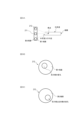
- FIG. Fig. 9A is a diagram showing how acoustic signals emitted from the auricle-side sound holes of a plurality of acoustic signal output devices 212 included in the acoustic signal output device array 211 form focal points.
- FIG. 9B is a diagram showing how the auricle-side sound holes are eccentric on the first end face of the acoustic signal output device 212.
- Fig. 9C is a diagram showing how the sound holes on the opposite side to the auricle side are eccentric on the second end face of the acoustic signal output device 212.
- an audio signal output device that realizes local reproduction based on a dipole sound source.
- local reproduction based on a dipole sound source refers to reproduction that utilizes the characteristics of a dipole sound source, in which the sound pressure is high only in the vicinity of the sound source and the sound pressure drops rapidly when moving away from the sound source.
- the reproduction method using a plurality of such audio signal output devices is theoretically equivalent to reproduction of a sound field based on the second kind of Rayleigh integral derived from the Kirchhoff-Helmholtz integral equation (see Reference Non-Patent Document 1).
- this reproduction method since the sound pressure is high only in the vicinity of each audio signal output device, the sounds leaking from each audio signal output device do not interfere with each other, and it is possible to prevent the amplification of sound leakage due to interference. Therefore, this reproduction method has the characteristic of less sound leakage to the surroundings.
- a dipole sound source is a sound source in which a positive phase sound source and a negative phase sound source are arranged adjacent to each other.
- a dipole sound source is described as an infinitesimal positive and negative dual sound source, the sound from the positive phase sound source and the sound from the negative phase sound source cancel each other out regardless of frequency, resulting in a directional characteristic of a figure of eight (see Reference Non-Patent Document 2).
- the size of the sound source is actually finite, the cancellation area becomes wider as the frequency of the sound that is easily diffracted (i.e., the wavelength is long).
- a single speaker driver unit can also be considered as a positive and negative dual sound source, so an acoustic signal output device that realizes local reproduction based on a dipole sound source can be configured using one speaker driver unit. An example of such a configuration will be described later.
- the Rayleigh integral of the second kind is an integral of the product of sound pressure and a dipole function on the plane S1, but in practice, the Rayleigh integral of the second kind can be regarded as the sum of the products of sound pressure and dipole function when dipole sound sources are discretely arranged. Therefore, a reproduction method using a plurality of sound signal output devices that realizes local reproduction based on a dipole sound source can be said to correspond to reproduction of a sound field based on the Rayleigh integral of the second kind.
- the acoustic signal output device 10 is an acoustic signal output device that outputs an acoustic signal from a dipole sound source, and can be used, for example, in open-ear headphones, which are acoustic listening devices worn without sealing the ear canal of a listener. As illustrated in Fig. 1, Fig. 2A, Fig. 2B, Fig. 2C, Fig. 3A, Fig. 3B, and Fig.
- the acoustic signal output device 10 has a driver unit 11 that converts an output signal (electrical signal representing an acoustic signal) output from a playback device into an acoustic signal and outputs it, and a housing 12 that houses the driver unit 11 inside.
- the driver unit (speaker driver unit) 11 is a device (device having a speaker function) that emits (emits sound) an acoustic signal AC1 (first acoustic signal) based on an input output signal to one side (D1 direction side) and emits an acoustic signal AC2 (second acoustic signal) that is an inverse phase signal (phase inversion signal) of the acoustic signal AC1 or an approximation signal of the inverse phase signal to the other side (D2 direction side).
- the acoustic signal emitted from the driver unit 11 to one side is called the acoustic signal AC1 (first acoustic signal)
- the acoustic signal emitted from the driver unit 11 to the other side is called the acoustic signal AC2 (second acoustic signal).
- the driver unit 11 includes a diaphragm 113 that emits the acoustic signal AC1 from one surface 113a in the D1 direction by vibration and emits the acoustic signal AC2 from the other surface 113b in the D2 direction by this vibration (see FIG. 2B).
- the driver unit 11 emits the acoustic signal AC1 from the surface 111 on one side in the D1 direction by vibrating the diaphragm 113 based on the input output signal, and emits the acoustic signal AC2, which is an inverse phase signal of the acoustic signal AC1 or an approximation of the inverse phase signal, from the other side 112 in the D2 direction. That is, the acoustic signal AC2 is emitted secondarily with the emission of the acoustic signal AC1.
- the D2 direction (the other side) is, for example, the opposite direction to the D1 direction (one side), but the D2 direction does not need to be strictly the opposite direction to the D1 direction, as long as the D2 direction is different from the D1 direction.
- the relationship between the one side (D1 direction) and the other side (D2 direction) depends on the type and shape of the driver unit 11.
- the acoustic signal AC2 may be strictly an inverse phase signal of the acoustic signal AC1, or the acoustic signal AC2 may be an approximation of the inverse phase signal of the acoustic signal AC1.
- the approximation signal of the opposite phase signal of the acoustic signal AC1 may be (1) a signal obtained by shifting the phase of the opposite phase signal of the acoustic signal AC1, (2) a signal obtained by changing (amplifying or attenuating) the amplitude of the opposite phase signal of the acoustic signal AC1, or (3) a signal obtained by shifting the phase of the opposite phase signal of the acoustic signal AC1 and further changing the amplitude.
- the phase difference between the opposite phase signal of the acoustic signal AC1 and its approximation signal is desirably ⁇ 1 % or less of one period of the opposite phase signal of the acoustic signal AC1.
- ⁇ 1 % are 1%, 3%, 5%, 10%, 20%, etc.
- the difference between the amplitude of the opposite phase signal of the acoustic signal AC1 and the amplitude of its approximation signal is desirably ⁇ 2 % or less of the amplitude of the opposite phase signal of the acoustic signal AC1.
- Examples of ⁇ 2 % are 1%, 3%, 5%, 10%, 20%, etc.
- examples of the type of the driver unit 11 include a dynamic type, a balanced armature chair type, a hybrid type of a dynamic type and a balanced armature type, and a condenser type.
- the shape of the driver unit 11 and the diaphragm 113 there is no limitation on the shape of the driver unit 11 and the diaphragm 113.
- the outer shape of the driver unit 11 is a substantially cylindrical shape with both end faces, and the diaphragm 113 is a substantially disc shape, but this does not limit the acoustic signal output device 10.
- the outer shape of the driver unit 11 may be a rectangular parallelepiped shape, and the diaphragm 113 may be a dome shape.
- examples of the acoustic signal are sounds such as music, voice, sound effects, and environmental sounds.
- acoustic signal AC1 and acoustic signal AC2 are acoustic signals from a positive-phase sound source and a negative-phase sound source, respectively.
- the housing 12 is a hollow member having a wall on the outside, and houses the driver unit 11 inside.
- the driver unit 11 is fixed to the end of the housing 12 on the D1 direction side.
- this does not limit the acoustic signal output device 10.
- the shape of the housing 12 is rotationally symmetric (line symmetric) or approximately rotationally symmetric about the axis A1 extending along the D1 direction. This makes it easy to provide a sound hole 123a (described in detail later) so that the variation in the energy of the sound emitted from the housing 12 for each direction is reduced. As a result, it becomes easy to reduce sound leakage uniformly in each direction.
- the housing 12 has a first end face which is a wall portion 121 arranged on one side (D1 direction side) of the driver unit 11, a second end face which is a wall portion 122 arranged on the other side (D2 direction side) of the driver unit 11, and a side face which is a wall portion 123 which surrounds the space between the first end face and the second end face and is centered on an axis line A1 passing through the first end face and the second end face (see FIG. 2B and FIG. 3B).
- the housing 12 has a substantially cylindrical shape with both end faces.
- the distance between the wall portion 121 and the wall portion 122 is 10 mm, and the walls 121 and 122 are circular with a radius of 10 mm.
- the housing 12 may be a substantially dome-shaped shape with walls at the ends, a hollow substantially cubic shape, or any other three-dimensional shape.
- the housing 12 may be made of a rigid body such as synthetic resin or metal, or may be made of an elastic body such as rubber.
- the wall of the housing 12 is provided with a sound hole 121a (first sound hole) for guiding the acoustic signal AC1 (first acoustic signal) emitted from the driver unit 11 to the outside, and a sound hole 121b (second sound hole) for guiding the acoustic signal AC2 (first acoustic signal) emitted from the driver unit 11 to the outside.
- the sound hole 121a and the sound hole 123a are, for example, through holes that penetrate the wall of the housing 12. However, this does not limit the acoustic signal output device 10. As long as the acoustic signals AC1 and AC2 can be output to the outside, the sound holes 121a and 123a do not have to be through holes. .
- the acoustic signal AC1 emitted from the sound hole 121a reaches the ear canal of the listener and is heard by the listener.
- an acoustic signal AC2 which is an inverse phase signal of the acoustic signal AC1 or an approximation of the inverse phase signal, is emitted from the sound hole 123a.
- a part of this acoustic signal AC2 cancels out a part of the acoustic signal AC1 emitted from the sound hole 121a (sound leakage component).
- the attenuation rate ⁇ 11 of the acoustic signal AC1 (first acoustic signal) at the position P2 (second point) based on the position P1 (first point) can be set to a predetermined value ⁇ th or less
- the attenuation amount ⁇ 12 of the acoustic signal AC1 (first acoustic signal) at the position P2 (second point) based on the position P1 (first point) can be set to a predetermined value ⁇ th or more.
- the position P1 (first point) is a predetermined point where the acoustic signal AC1 (first acoustic signal) emitted from the sound hole 121a (first sound hole) arrives.
- the position P2 (second point) is a predetermined point that is farther away from the acoustic signal output device 10 than the position P1 (first point).
- the predetermined value ⁇ th is a value smaller (lower) than the attenuation rate ⁇ 21 of an arbitrary or specific acoustic signal (sound) due to air propagation at a position P2 (second position) based on the position P1 (first position).
- the predetermined value ⁇ th is a value larger than the attenuation amount ⁇ 22 of an arbitrary or specific acoustic signal (sound) due to air propagation at a position P2 (second position) based on the position P1 (first position). That is, the acoustic signal output device 10 is designed so that the attenuation rate ⁇ 11 is equal to or smaller than a predetermined value ⁇ th smaller than the attenuation rate ⁇ 21 , or the attenuation amount ⁇ 12 is equal to or larger than a predetermined value ⁇ th larger than the attenuation amount ⁇ 22.
- the acoustic signal AC1 is propagated through the air from the position P1 to the position P2, and is attenuated due to this air propagation and the acoustic signal AC2.
- the attenuation rate ⁇ 11 is the ratio (AMP2 (AC1)/AMP1(AC1)) of the magnitude AMP2 (AC1) of the acoustic signal AC1 at position P2 attenuated due to air propagation and acoustic signal AC2 to the magnitude AMP1 (AC1) of the acoustic signal AC1 at position P1.
- the attenuation amount ⁇ 12 is the difference (
- any or a specific acoustic signal ACar propagated through the air from position P1 to position P2 is attenuated due to air propagation, not due to the acoustic signal AC2.
- the attenuation rate ⁇ 21 is the ratio ( AMP2(ACar)/AMP1 ( ACar )) of the magnitude AMP2 ( ACar ) of the acoustic signal ACar at position P2 attenuated due to air propagation (attenuation without being due to the acoustic signal AC2) to the magnitude AMP1( ACar ) of the acoustic signal ACar at position P1.
- the attenuation amount ⁇ 22 is the difference (
- the magnitude of the acoustic signal include the sound pressure of the acoustic signal or the energy of the acoustic signal.
- the "sound leakage component" means, for example, a component of the acoustic signal AC1 emitted from the sound hole 121a that is likely to reach an area other than that of the listener wearing the acoustic signal output device 10 (for example, a person other than the listener wearing the acoustic signal output device 10).
- the "sound leakage component” means a component of the acoustic signal AC1 that propagates in a direction other than the D1 direction.
- the direct wave of the acoustic signal AC1 is mainly emitted from the sound hole 121a
- the direct wave of the second acoustic signal is mainly emitted from the second sound hole.
- a part of the direct wave of the acoustic signal AC1 emitted from the sound hole 121a (sound leakage component) is offset by interference with at least a part of the direct wave of the acoustic signal AC2 emitted from the sound hole 123a.
- this does not limit the acoustic signal output device 10, and this offsetting can occur with other than direct waves.
- the sound leakage component which is at least one of the direct wave and the reflected wave of the acoustic signal AC1 emitted from the sound hole 121a, may be cancelled out by at least one of the direct wave and the reflected wave of the acoustic signal AC2 emitted from the sound hole 123a. This makes it possible to suppress sound leakage.
- the following shows an example of the arrangement of sound holes 121a and 123a.
- Sound hole 121a (first sound hole) is provided in area AR1 (first area) of wall 121 arranged on one side of driver unit 11 (the D1 direction side where acoustic signal AC1 is emitted) (see Figures 1, 2A, 2B, and 3B). That is, sound hole 121a opens facing the D1 direction (first direction) along axis A1. Also, sound hole 123a (second sound hole) is provided in area AR3 of wall 123 adjacent to area AR between area AR1 (first area) of wall 121 of housing 12 and area AR2 (second area) of wall 122 arranged on the D2 direction side of driver unit 11 (the other side where acoustic signal AC2 is emitted).
- the sound hole 121a first sound hole
- the sound hole 123a second sound hole
- the housing 12 has a first end face which is a wall portion 121 arranged on one side (D1 direction side) of the driver unit 11, a second end face which is a wall portion 122 arranged on the other side (D2 direction side) of the driver unit 11, and a side face which is a wall portion 123 which surrounds the space between the first end face and the second end face and is centered on an axis A1 along the emission direction (D1 direction) of the acoustic signal AC1 passing through the first end face and the second end face (see FIG. 2B and FIG. 3B), the sound hole 121a (first sound hole) is provided on the first end face, and the sound hole 123a (second sound hole) is provided on the side face.
- no sound hole is provided on the wall portion 122 side of the housing 12. If a sound hole is provided on the wall portion 122 side of the housing 12, the sound pressure level of the acoustic signal AC2 emitted from the housing 12 exceeds the level required to offset the sound leakage component of the acoustic signal AC1, and the excess is perceived as sound leakage.
- the sound hole 121a is disposed on or near the axis A1 along the emission direction (D1 direction) of the acoustic signal AC1.
- the axis A1 passes through the center or near the center of the area AR1 (first area) of the wall 121 disposed on one side (D1 direction side) of the driver unit 11 of the housing 12.
- the axis A1 is an axis extending in the D1 direction through the central area of the housing 12. That is, the sound hole 121a is provided at the central position of the area AR1 of the wall 121 of the housing 12.
- the edge shape of the open end of the sound hole 121a is a circle (the open end is circular).
- the radius of such a sound hole 121a is, for example, 3.5 mm.
- this does not limit the acoustic signal output device 10.
- the edge shape of the open end of the sound hole 121a may be other shapes such as an ellipse, a rectangle, a triangle, etc.
- the open end of the sound hole 121a may be in a mesh pattern. In other words, the open end of the sound hole 121a may be composed of multiple holes.
- one sound hole 121a is provided in the area AR1 (first area) of the wall 121 of the housing 12.
- this does not limit the acoustic signal output device 10.
- two or more sound holes 121a may be provided in the area AR1 (first area) of the wall 121 of the housing 12.
- the sound hole 123a (second sound hole) be positioned taking into consideration the following points, for example:
- Sound hole 123a is positioned so that the propagation path of the sound leakage component of sound signal AC1 to be cancelled overlaps with the propagation path of sound signal AC2 emitted from sound hole 123a.
- the propagation area of the acoustic signal AC2 emitted from the sound hole 123a and the frequency characteristics of the housing 12 vary depending on the opening area of the sound hole 123a. Furthermore, the frequency characteristics of the housing 12 affect the frequency characteristics of the acoustic signal AC2 emitted from the sound hole 123a, i.e., the amplitude at each frequency. Taking into consideration the propagation area and frequency characteristics of the acoustic signal AC2 emitted from the sound hole 123a, the opening area of the sound hole 123a is determined so that in the area where the sound leakage components are to be cancelled out, the sound leakage components are cancelled out by the acoustic signal AC2 emitted from the sound hole 123a.
- the sound hole 123a (second sound hole) be configured as follows, for example.
- the sound holes 123a are provided along a circumference (circle) C1 centered on the axis A1 along the emission direction of the acoustic signal AC1 (first acoustic signal).
- the acoustic signal AC2 is emitted radially (radially centered on the axis A1) from the sound holes 123a to the outside.
- the sound leakage component of the acoustic signal AC1 is also emitted radially (radially centered on the axis A1) from the sound hole 121a to the outside.
- the sound leakage component of the acoustic signal AC1 can be appropriately canceled by the acoustic signal AC2.
- an example is shown in which multiple sound holes 123a are provided on the circumference C1.
- the multiple sound holes 123a are provided along the circumference C1, and it is not necessary that all of the sound holes 123a are positioned strictly on the circumference C1.
- the sum of the opening areas of the sound holes 123a (second sound holes) provided along a first arc region, which is any of the unit arc regions, is the same or approximately the same as the sum of the opening areas of the sound holes 123a (second sound holes) provided along a second arc region, which is any of the unit arc regions excluding the first arc region.
- the sum of the opening areas of the sound holes 123a (second sound holes) provided along a first arc region which is any of the unit arc regions
- the sum of the opening areas of the sound holes 123a (second sound holes) provided along a second arc region which is any of the unit arc regions excluding the first arc region.
- the sum of the opening areas of the sound holes 123a (second sound holes) provided along a first arc region (for example, unit arc region C1-1) that is one of the unit arc regions C1-1, ..., C1-4 is the same or approximately the same as the sum of the opening areas of the sound holes 123a (second sound holes) provided along a second arc region (for example, unit arc region C1-2) that is one of the unit arc regions excluding the first arc region.
- the sound pressure distribution of the acoustic signal AC2 emitted from the sound hole 123a provided along the first arc region and the sound pressure distribution of the acoustic signal AC2 emitted from the sound hole 123a provided along the second arc region are point symmetric or approximately point symmetric with respect to the axis A1.
- the sums of the opening areas of the sound holes 123a (second sound holes) provided along each unit arc region are all the same or approximately the same.
- the sound pressure distribution of the acoustic signal AC2 emitted from the sound hole 123a is point symmetric or approximately point symmetric with respect to the axis A1.
- the sound leakage component of the acoustic signal AC1 can be more appropriately canceled out by the acoustic signal AC2.
- the multiple sound holes 123a are arranged along the circumference C1 with the same shape, size, and spacing.
- multiple sound holes 123a with a width of 4 mm and a height of 3.5 mm are arranged along the circumference C1 with the same shape, size, and spacing.
- the sound leakage components of the acoustic signal AC1 can be more appropriately cancelled out by the acoustic signal AC2.
- sound hole 123a (second sound hole) is provided in a wall portion adjacent to area AR located on the other side (D2 direction side) of driver unit 11 (see FIG. 3B). This allows the direct wave of acoustic signal AC2 emitted from the other side of driver unit 11 to be efficiently guided to the outside from sound hole 123a. As a result, the sound leakage component of acoustic signal AC1 can be more appropriately cancelled out by acoustic signal AC2.
- the edge of the open end of the sound hole 123a is rectangular (the open end is square), but this does not limit the acoustic signal output device 10.
- the edge of the open end of the sound hole 123a may be circular, elliptical, triangular, or other shapes.
- the open end of the sound hole 123a may also be mesh-like.
- the open end of the sound hole 123a may be composed of multiple holes.
- There is also no limit to the number of sound holes 123a and a single sound hole 123a may be provided in the area AR3 of the wall 123 of the housing 12, or multiple sound holes 123a may be provided.
- the ratio S2 / S1 of the sum S2 of the opening areas of the sound holes 123a (second sound holes) to the sum S1 of the opening areas of the sound holes 121a (first sound holes) satisfies 2/3 ⁇ S2 / S1 ⁇ 4. This allows the sound leakage component of the acoustic signal AC1 to be appropriately cancelled out by the acoustic signal AC2.
- the sound leakage suppression performance may also depend on the ratio between the area of the wall 123 in which the sound hole 123a is provided and the opening area of the sound hole 123a.
- the housing 12 has a first end face which is the wall 121 arranged on one side (D1 direction side) of the driver unit 11, a second end face which is the wall 122 arranged on the other side (D2 direction side) of the driver unit 11, and a side face which is the wall 123 surrounding the space between the first end face and the second end face around the axis A1 along the emission direction (D1 direction) of the acoustic signal AC1 passing through the first end face and the second end face, and the sound hole 121a (first sound hole) is provided on the first end face, and the sound hole 123a (second sound hole) is provided on the side face (see FIG.
- the ratio S2 / S3 of the sum S2 of the opening areas of the sound holes 123a to the total area S3 of the side surfaces is 1/20 ⁇ S2 / S3 ⁇ 1/5. This allows the sound leakage component of the acoustic signal AC1 to be appropriately cancelled by the acoustic signal AC2. However, this does not limit the acoustic signal output device 10.
- Fig. 5 to Fig. 7 are all diagrams showing the configuration of the headphone device 20, with Fig. 5 being a front view of the headphone device 20 seen from the front, Fig. 6 being a side view of the headphone device 20 seen from the left side, and Fig. 7 being a top view of the headphone device 20 seen from above.
- the headphone device 20 includes a right headphone 21R, a left headphone 21L, and a headband 22.
- the headphone device 20 is configured such that the right headphone 21R and the left headphone 21L are connected to the left and right ends of the headband 22.
- Both the right headphone 21R and the left headphone 21L have an acoustic signal output device array 211.
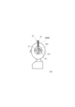
- the acoustic signal output device array 211 includes a plurality of acoustic signal output devices 212 arranged to surround the pinna of the listener (see Fig. 6).
- the acoustic signal output device 212 is an acoustic signal output device that realizes local reproduction based on a dipole sound source, and is, for example, the acoustic signal output device 10 described in ⁇ Technical Background>. Therefore, the acoustic signal output device array 211 is configured to reproduce a sound field based on the Rayleigh integral of the second kind in the vicinity of the pinna.
- the acoustic signal output device array 211 is configured as a frame-like structure surrounding the auricle, which serves as the framework of the headphone device 20, and multiple acoustic signal output devices 212 may be provided on the frame so as to surround the auricle (see FIG. 8).
- the headphone device 20 becomes an open-type headphone, which allows the headphone device 20 to take in sounds around the listener without blocking them, and allows the listener to easily hear sounds that warn of danger, such as horns, warning sounds, and alarms, even when the headphone device 20 is used outdoors.
- the input signal of the acoustic signal output device 212 included in the acoustic signal output device array 211 may be a signal picked up by a sound pressure type microphone arranged at a position corresponding to the position of the acoustic signal output device 212, out of signals picked up using a microphone array including a plurality of sound pressure type microphones arranged at positions corresponding to the positions of the acoustic signal output devices 212 included in the acoustic signal output device array 211.
- the input signal of the acoustic signal output device 212 included in the acoustic signal output device array 211 may be a sound pressure signal at a position corresponding to the position of the acoustic signal output device 212 included in the acoustic signal output device array 211, calculated using the boundary element method.
- FIG. 6 illustrates an acoustic signal output device array 211 in which multiple acoustic signal output devices 212 are arranged in a circle
- the arrangement shape does not necessarily have to be circular, and may be elliptical, rectangular, or even other shapes. In other words, it is sufficient that the multiple acoustic signal output devices 212 are arranged so as to surround the auricle.
- an acoustic signal output device 212 that has a substantially cylindrical housing with both end faces (hereinafter, the end face on the auricle side is referred to as the first end face, and the end face opposite the auricle side is referred to as the second end face) like the acoustic signal output device 10 in Fig.
- the auricle side sound hole for emitting a desired acoustic signal (hereinafter, referred to as the first acoustic signal) on the first end face
- a sound hole for emitting an acoustic signal of substantially opposite phase to the acoustic signal (an opposite phase acoustic signal or an approximate signal thereof, hereinafter, referred to as the second acoustic signal) on the second end face.
- each acoustic signal output device 212 included in the acoustic signal output device array 211 is arranged so that the first acoustic signal arrives with a focus on either a point near the entrance of the ear canal, a point on the eardrum, or a point between the entrance of the ear canal and the eardrum (see Fig. 9A), thereby making it possible to reduce the sound emitted from each acoustic signal output device 212 included in the acoustic signal output device array 211 and to further suppress sound leakage.
- the first end face on which the sound hole on the pinna side is provided may be arranged to face the entrance of the ear canal, and the sound hole on the pinna side may be arranged so as to be eccentric on the first end face (see FIG. 9B). Also, when the sound hole on the side opposite the pinna side is provided on the second end face, the sound hole may be arranged so as to be eccentric on the second end face (see FIG. 9C).
- the present invention it is possible to reproduce sound so that it cannot be heard by anyone other than the listener, thereby suppressing sound leakage.
- multiple acoustic signal output devices that realize localized reproduction based on a dipole sound source, it is possible to localize the sound field at any position.
Landscapes
- Physics & Mathematics (AREA)
- Engineering & Computer Science (AREA)
- Acoustics & Sound (AREA)
- Health & Medical Sciences (AREA)
- Otolaryngology (AREA)
- Signal Processing (AREA)
- Multimedia (AREA)
- Soundproofing, Sound Blocking, And Sound Damping (AREA)
Priority Applications (2)
| Application Number | Priority Date | Filing Date | Title |
|---|---|---|---|
| JP2025525518A JPWO2024252550A1 (https=) | 2023-06-07 | 2023-06-07 | |
| PCT/JP2023/021134 WO2024252550A1 (ja) | 2023-06-07 | 2023-06-07 | ヘッドホン装置、音響信号出力方法 |
Applications Claiming Priority (1)
| Application Number | Priority Date | Filing Date | Title |
|---|---|---|---|
| PCT/JP2023/021134 WO2024252550A1 (ja) | 2023-06-07 | 2023-06-07 | ヘッドホン装置、音響信号出力方法 |
Publications (1)
| Publication Number | Publication Date |
|---|---|
| WO2024252550A1 true WO2024252550A1 (ja) | 2024-12-12 |
Family
ID=93795580
Family Applications (1)
| Application Number | Title | Priority Date | Filing Date |
|---|---|---|---|
| PCT/JP2023/021134 Ceased WO2024252550A1 (ja) | 2023-06-07 | 2023-06-07 | ヘッドホン装置、音響信号出力方法 |
Country Status (2)
| Country | Link |
|---|---|
| JP (1) | JPWO2024252550A1 (https=) |
| WO (1) | WO2024252550A1 (https=) |
Citations (1)
| Publication number | Priority date | Publication date | Assignee | Title |
|---|---|---|---|---|
| WO2023084574A1 (ja) * | 2021-11-09 | 2023-05-19 | 日本電信電話株式会社 | 音響信号出力装置 |
-
2023
- 2023-06-07 JP JP2025525518A patent/JPWO2024252550A1/ja active Pending
- 2023-06-07 WO PCT/JP2023/021134 patent/WO2024252550A1/ja not_active Ceased
Patent Citations (1)
| Publication number | Priority date | Publication date | Assignee | Title |
|---|---|---|---|---|
| WO2023084574A1 (ja) * | 2021-11-09 | 2023-05-19 | 日本電信電話株式会社 | 音響信号出力装置 |
Also Published As
| Publication number | Publication date |
|---|---|
| JPWO2024252550A1 (https=) | 2024-12-12 |
Similar Documents
| Publication | Publication Date | Title |
|---|---|---|
| JP7582280B2 (ja) | 音響システム | |
| JP5363825B2 (ja) | ノイズキャンセルヘッドホン | |
| US9613614B2 (en) | Noise-reducing headphone | |
| GB2454605A (en) | Noise-cancelling ear-worn speaker-carrying devices with vents to bypass seals and cancel sound leakage | |
| US12513456B2 (en) | Sound system | |
| CN204305320U (zh) | 降噪耳机 | |
| JP6932029B2 (ja) | ホーンスピーカー、スピーカーユニット、メガホン、アダプター、及び放送システム | |
| WO2024252550A1 (ja) | ヘッドホン装置、音響信号出力方法 | |
| JP7622750B2 (ja) | スピーカシステム | |
| WO2024252549A1 (ja) | ヘッドホン装置、音響信号出力方法 | |
| EP3673482A1 (en) | Noise cancellation headphone | |
| WO2023187900A1 (ja) | 音響システム | |
| JP7785641B2 (ja) | 音響信号出力装置 | |
| WO2022215109A1 (ja) | キャンセル装置 | |
| JP7364044B2 (ja) | スピーカシステム | |
| WO2024100815A1 (ja) | 音響信号出力装置 | |
| WO2024100817A1 (ja) | 音響信号出力装置 | |
| WO2024100816A1 (ja) | 音響信号出力装置 | |
| WO2024100822A1 (ja) | 音響信号出力装置 | |
| US20240236559A9 (en) | Sound system | |
| WO2024150792A1 (ja) | 音響信号出力装置 | |
| CN120835238A (zh) | 开放式耳机 | |
| JPS6224998B2 (https=) |
Legal Events
| Date | Code | Title | Description |
|---|---|---|---|
| 121 | Ep: the epo has been informed by wipo that ep was designated in this application |
Ref document number: 23940654 Country of ref document: EP Kind code of ref document: A1 |
|
| ENP | Entry into the national phase |
Ref document number: 2025525518 Country of ref document: JP Kind code of ref document: A |
|
| NENP | Non-entry into the national phase |
Ref country code: DE |