WO2024252546A1 - 音響信号制御装置及び方法 - Google Patents
音響信号制御装置及び方法 Download PDFInfo
- Publication number
- WO2024252546A1 WO2024252546A1 PCT/JP2023/021112 JP2023021112W WO2024252546A1 WO 2024252546 A1 WO2024252546 A1 WO 2024252546A1 JP 2023021112 W JP2023021112 W JP 2023021112W WO 2024252546 A1 WO2024252546 A1 WO 2024252546A1
- Authority
- WO
- WIPO (PCT)
- Prior art keywords
- sound
- acceleration
- sound image
- image position
- engine
- Prior art date
- Legal status (The legal status is an assumption and is not a legal conclusion. Google has not performed a legal analysis and makes no representation as to the accuracy of the status listed.)
- Ceased
Links
Images




Classifications
-
- H—ELECTRICITY
- H04—ELECTRIC COMMUNICATION TECHNIQUE
- H04S—STEREOPHONIC SYSTEMS
- H04S7/00—Indicating arrangements; Control arrangements, e.g. balance control
- H04S7/30—Control circuits for electronic adaptation of the sound field
- H04S7/302—Electronic adaptation of stereophonic sound system to listener position or orientation
-
- G—PHYSICS
- G10—MUSICAL INSTRUMENTS; ACOUSTICS
- G10K—SOUND-PRODUCING DEVICES; METHODS OR DEVICES FOR PROTECTING AGAINST, OR FOR DAMPING, NOISE OR OTHER ACOUSTIC WAVES IN GENERAL; ACOUSTICS NOT OTHERWISE PROVIDED FOR
- G10K15/00—Acoustics not otherwise provided for
- G10K15/02—Synthesis of acoustic waves
-
- G—PHYSICS
- G10—MUSICAL INSTRUMENTS; ACOUSTICS
- G10K—SOUND-PRODUCING DEVICES; METHODS OR DEVICES FOR PROTECTING AGAINST, OR FOR DAMPING, NOISE OR OTHER ACOUSTIC WAVES IN GENERAL; ACOUSTICS NOT OTHERWISE PROVIDED FOR
- G10K15/00—Acoustics not otherwise provided for
- G10K15/08—Arrangements for producing a reverberation or echo sound
- G10K15/12—Arrangements for producing a reverberation or echo sound using electronic time-delay networks
-
- B—PERFORMING OPERATIONS; TRANSPORTING
- B60—VEHICLES IN GENERAL
- B60Q—ARRANGEMENT OF SIGNALLING OR LIGHTING DEVICES, THE MOUNTING OR SUPPORTING THEREOF OR CIRCUITS THEREFOR, FOR VEHICLES IN GENERAL
- B60Q9/00—Arrangement or adaptation of signal devices not provided for in one of main groups B60Q1/00 - B60Q7/00, e.g. haptic signalling
-
- H—ELECTRICITY
- H04—ELECTRIC COMMUNICATION TECHNIQUE
- H04R—LOUDSPEAKERS, MICROPHONES, GRAMOPHONE PICK-UPS OR LIKE ACOUSTIC ELECTROMECHANICAL TRANSDUCERS; ELECTRIC HEARING AIDS; PUBLIC ADDRESS SYSTEMS
- H04R2499/00—Aspects covered by H04R or H04S not otherwise provided for in their subgroups
- H04R2499/10—General applications
- H04R2499/13—Acoustic transducers and sound field adaptation in vehicles
-
- H—ELECTRICITY
- H04—ELECTRIC COMMUNICATION TECHNIQUE
- H04S—STEREOPHONIC SYSTEMS
- H04S2400/00—Details of stereophonic systems covered by H04S but not provided for in its groups
- H04S2400/11—Positioning of individual sound objects, e.g. moving airplane, within a sound field
-
- H—ELECTRICITY
- H04—ELECTRIC COMMUNICATION TECHNIQUE
- H04S—STEREOPHONIC SYSTEMS
- H04S2400/00—Details of stereophonic systems covered by H04S but not provided for in its groups
- H04S2400/13—Aspects of volume control, not necessarily automatic, in stereophonic sound systems
-
- H—ELECTRICITY
- H04—ELECTRIC COMMUNICATION TECHNIQUE
- H04S—STEREOPHONIC SYSTEMS
- H04S7/00—Indicating arrangements; Control arrangements, e.g. balance control
- H04S7/30—Control circuits for electronic adaptation of the sound field
- H04S7/305—Electronic adaptation of stereophonic audio signals to reverberation of the listening space
Definitions
- the present disclosure relates to an audio signal control device and method.
- Patent Document 1 has the following problems. For example, if there is a difference between the actual acceleration of the moving object and the acceleration the driver feels by listening to the engine sound, the driver will feel uncomfortable. Specifically, when the accelerator is opened and the engine speed only increases without increasing the speed, the driver will feel uncomfortable, such as "the acceleration is not linear, it is slow.” This conventional technology cannot auditorily compensate for the difference between the actual acceleration of the moving object and the acceleration the driver feels by listening to the engine sound, and cannot reduce the discomfort the driver feels when driving a moving object.
- the present disclosure has been made to solve the above-mentioned problems, and aims to reduce the discomfort felt by a driver when boarding and driving a moving body by auditorily compensating for the difference between the actual acceleration of the moving body and the acceleration that the driver feels by listening to the engine sound.
- the audio signal control device comprises: a sound effect generating unit that generates a plurality of sound effects using a pseudo engine sound, which is an acoustic signal that reproduces an engine sound generated by a moving object or a simulator that simulates the operation of the moving object;
- the vehicle has a sound image position control unit that controls a sound image position, which is a position where sound images of the multiple sound effects are located, based on an acceleration of the moving body or the simulator and an estimated value of an audible acceleration, which is the acceleration experienced by an occupant of the moving body or the simulator by listening to the engine sound.
- the sound effects 103a to 103d are sent to the driver 24 of the vehicle 20 using the speakers 23a to 23d, respectively. If a passenger 25 other than the driver 24 is also on board the vehicle 20, the generated sound effects 103a to 103d may also be sent to the passenger 25.
- the acceleration that the driver 24 feels when listening to the engine sound is a psychologically perceived acceleration that is recalled based on the driver 24's past experiences. Specifically, if the volume of the engine sound increases or the frequency of the engine sound increases with an increase in engine speed, the driver 24 feels as if the moving object 20 is accelerating.
- the acceleration experienced by the driver 24 by listening to the engine sound is distinguished between the psychologically perceived acceleration recalled based on the driver's 24's past experiences as “auditory acceleration” and the perceived acceleration induced by the movement of the pseudo engine sound 102 (i.e., auditory vection) as “auditory vection acceleration”. Note that, since the engine sound is also heard by passengers 25 other than the driver 24, passengers 25 other than the driver 24 may be included in the definitions of auditory acceleration and auditory vection acceleration.
- the position of the sound image 26 can also be freely controlled by a psychological acoustic effect called the "precedence effect.”
- the "precedence effect” is a phenomenon in which, for example, when the same sound is sent from two different directions, if there is a delay in one of the sounds, the sound is heard as one sound coming from the direction of the sound that reaches the ear first. Due to the "precedence effect," the position of the sound image 26 changes according to the arrival time difference between sounds from multiple different directions.
- the position of the sound image 26 can be freely controlled by controlling the delay times of the multiple sound effects. In other words, the driver 24 can be made to perceive various changes in the position of the sound image 26.
- the sound image position calculation unit 7 calculates a sound image position 106 indicating the position of a sound image 26 perceived by the driver 24, which is a sound image generated by a plurality of sound effects 103, based on the audible acceleration information 105 and the speed information 104. More specifically, if there is a difference between the audible acceleration A' felt by the driver 24 from the engine sound and the actual acceleration A of the moving body 20, the sound image position 106 is calculated so as to move the sound image 26.
- the speed information 104 is information that indicates the actual moving speed and moving direction of the moving body 20.
- the speed information 104 can be obtained from a vehicle speed sensor provided in the moving body 20, information from the steering angle of the steering wheel, a Global Positioning System (GPS), an Inertial Measurement Unit (IMU), the ECU 22 of the moving body 20, etc.
- the speed information 104 may be obtained at predetermined frame periods, similar to the frame period of the pseudo engine sound 102, but does not have to be synchronized with the frame period of the pseudo engine sound 102.
- the actual acceleration A of the moving body 20 can be calculated from the derivative of the speed of the moving body 20 or the difference per predetermined time period using the speed information 104.
- the actual acceleration A of the moving body 20 may also be calculated directly from an acceleration sensor provided in the moving body 20.
- the number of the current frame is t
- the auditory acceleration of the current frame and the actual acceleration of the moving object 20 in the current frame are A'(t) and A(t), respectively.
- the acceleration at which the sound image 26 moves i.e., the auditory vection acceleration
- the direction of movement of the sound image 26 is limited to only the traveling direction of the moving object 20
- the distance that the sound image 26 moves per frame i.e., the amount of displacement of the position of the sound image
- ⁇ x(t) can be expressed, for example, by equation (2).
- ⁇ x(t) which is the difference between the sound image position (x(t)) of the sound image 26 in the current frame and the sound image position (x(t-1)) in the previous frame, becomes larger as the difference between the audible acceleration A' and the actual acceleration A of the moving body 20 becomes larger.
- the greater the difference between the two accelerations the greater the distance the sound image 26 moves.
- the example of equation (2) is a case in which the difference between the audible acceleration A' and the actual acceleration of the moving body 20 is compensated for, but this is not limited to this. For example, a stronger sense of acceleration may be created by making the acceleration a(t) of the movement of the sound image position 106 larger than the actual acceleration A of the moving body 20.
- acoustic signal transmission characteristics in the vehicle cabin are affected by reflection or diffraction by the seats, window glass, etc., but for simplicity, the vehicle cabin is described as a free sound field that is not affected by reflection or diffraction.
- the effects of reflection or diffraction in the vehicle cabin can be reduced, for example, by a filter having the inverse characteristics of the acoustic space characteristics in the vehicle cabin.
- the acoustic space characteristics in the vehicle cabin can be obtained from an impulse response.
- a reference signal such as a time stretched pulse (TSP) is sent from each speaker, and the reference signal is acquired using a microphone installed at the position of the driver 25, thereby obtaining an impulse response.
- TSP time stretched pulse
- a filter coefficient having the inverse characteristics of the acoustic space characteristics can be calculated from the impulse response.
- sound image 26a is localized in the center between the two front speakers using only speakers 23a and 23b.
- the distance from speaker 23a to sound image 26a is equal to the distance from speaker 23b to sound image 26a, so delay time 107a and delay time 107b can be set to the same value.
- the arrival time of sound effect 103a sent from speaker 23a to sound image 26a will be the same as the arrival time of sound effect 103b sent from speaker 23b to sound image 26a. Therefore, sound image 26a generated by sound effect 103a and sound effect 103b will be localized in the center between the two front speakers.
- delay time 107c and delay time 107d can be set to the same value.
- the arrival time of sound effect 103c sent from speaker 23c to sound image 26b will be the same as the arrival time of sound effect 103d sent from speaker 23d to sound image 26b. Therefore, sound image 26b generated by sound effect 103c and sound effect 103d will be localized in the center between the two rear speakers.
- sound image 26 is moved back and forth on line segment CL using four speakers, speakers 23a to 23d. If delay times 107a to 107d are all set to the same value, the arrival times of sound effects 103a to 103d sent from speakers 23a to 23d to sound image 26 will all be the same. Therefore, sound image 26 will be localized at the center position of the four speakers. Note that sound image 26 can be considered to be a sound image generated by sound images 26a and 26b in appearance. Therefore, if a certain time difference is given between the set of delay times 107a and 107b and the set of delay times 107c and 107d, a "precedence effect" will occur between sound images 26a and 26b.
- the delay time of the pair of delay times 107c and 107d should be made shorter than the delay time of the pair of delay times 107a and 107b. That is, by controlling the delay time between the front and rear speakers, it is possible to move the sound image 26 forward or backward.
- the above describes an example of moving sound image 26 in the forward/backward direction.
- a certain time difference is provided between the delay time of the right speaker (i.e., the set of delay times 107a and 107c) and the delay time of the left speaker (i.e., the set of delay times 107b and 107d). Therefore, by controlling the delay times of multiple sound effects, it is possible to freely control the position of sound image 26.
- the arrival time difference between each of the multiple sound effects 103 is determined according to the sound image position (x(t)) of the current frame indicated by the sound image position 106.
- the delay time calculation unit 8 calculates the delay times of the sound effects 103a to 103d according to the determined arrival time differences, and outputs them as delay times 107a to 107d, respectively.
- the sense of acceleration (or deceleration) of the moving body 20 is audibly enhanced by moving the sound image 26 in front of and behind the driver 24, but this is not limited to the above.
- the sound image 26 may be moved from the right side of the driver 24 to the left side (or from the left side to the right side) according to the speed information 104.
- By moving the sound image 26 left and right it is possible to create a sense of turning of the moving body 20 for the driver 24, thereby increasing the satisfaction level when driving.
- speakers 23a to 23d are arranged horizontally, but the arrangement of the speakers is not limited to horizontal.
- the speakers may be arranged above or below the driver 24, such as by placing speaker 23b above the driver 24 and speaker 23d at the driver's feet.
- the sound image 26 can also be moved in the vertical direction of the driver 24.
- the discomfort felt when driving a moving body capable of three-dimensional movement can be reduced.
- the processor 30 controls the entire audio signal control device 1.
- the processor 30 is a CPU (Central Processing Unit), an FPGA (Field Programmable Gate Array), a DSP (Digital Signal Processor), etc.
- the processor 30 may be a single processor or a multi-processor.
- the audio signal control device 1 may have a processing circuit such as an ASIC (Application Specific Integrated Circuit) in addition to a computer.
- the processing circuit may be a single circuit or a composite circuit.
- the memory 31 is the main memory device of the acoustic signal control device 1.
- the memory 31 holds data necessary for the operation of the processor 30.
- the memory 31 is a RAM (Random Access Memory).
- the storage device 32 is an auxiliary storage device for the acoustic signal control device 1.
- the storage device 32 stores initial value data, programs, error logs, etc. required for the operation of the acoustic signal control device 1.
- the storage device 32 is a ROM (Read Only Memory), HDD (Hard Disk Drive), or SSD (Solid State Drive).
- the interface 33 is an input/output interface for sending and receiving data to and from external devices connected to the audio signal control device 1.
- the interface 33 is a NIC (Network Interface Controller).
- the external devices are the D/A 27 and the ECU 22.
- the interface 33 inputs the engine sound information 101 and speed information 104 output from the ECU 22 to the processor 30.
- the interface 33 outputs multiple sound effects 103 output from the processor 30 to the D/A 27.
- the interface 33 is also a device that inputs information necessary for controlling the audio signal control device 1 and execution commands for the control processing of the audio signal control device 1.
- the acoustic signal control device 1 is mounted on the mobile object 20, but is not limited to this.
- the mobile object 20 is a driving simulator, it may be configured by a computer or the like located in a different location from the mobile object 20.
- various information about the mobile object 20 may be input to the acoustic signal control device 1 on the computer by data transmission via a communication network connected to the interface 33.
- the multiple sound effects 103 generated by the acoustic signal control device 1 on the computer may be sent to the D/A 27 of the mobile object 20 via a communication network.
- the communication network may be, for example, a wired or wireless network, such as a dedicated line such as a LAN (Local Area Network), or the Internet.
- step ST5 the sound signal control unit 5 generates multiple sound effects 103 by delaying the pseudo engine sound 102 according to multiple delay times 107 (step ST5).
- the gain calculation unit 10 calculates gains indicating the volume of the multiple sound effects 103 according to the sound image position 106 indicating the position where the sound image 26 is localized.
- the obtained gains are output as multiple gains 108.
- the multiple gains 108 are all or part of the gains 108a to 108d. Note that when there is no need to explain the gains 108a to 108d individually, they will be abbreviated as multiple gains 108.
- the volume of the sound effect sent from the rear speaker is made larger than the volume of the sound effect sent from the front speaker. That is, the gain of the pair of gains 108c and 108d is made larger than the gain of the pair of gains 108a and 108b. Therefore, by controlling the volume of each of the multiple sound effects 103, it is possible to freely control the position of the sound image 26.
- step ST5A the sound signal control unit 5 generates multiple sound effects 103 by controlling the volume of the pseudo engine sound 102 according to multiple gains 108 (step ST5A).
- the acoustic signal control device of this embodiment can auditorily compensate for the difference between the actual acceleration of the moving body and the acceleration that the driver feels by listening to the engine sound by moving the position where the sound image of the pseudo engine sound is located, thereby reducing the sense of discomfort felt by the driver when he or she is in the moving body and driving.
- Embodiment 3 the sound image position is controlled by delaying each of the multiple sound effects, but the method of controlling the sound image position is not limited to delay. For example, it is possible to control the sound image position by adding reverberation to each of the multiple sound effects. This will be described as a third embodiment.
- a sound source with a long reverberation time is perceived as being affected by reflection or diffraction to a large extent, and is therefore perceived as a sound source coming from a distance.
- a sound source with a short reverberation time is perceived as being affected by reflection or diffraction to a small extent, and is therefore perceived as a nearby sound source.
- the reverberation time of the sound effect sent from the front speakers is made shorter than the reverberation time of the sound effect sent from the rear speakers.
- the reverberation time of the pair of reverberation times 109a and 109b should be made shorter than the reverberation time of the pair of reverberation times 109c and 109d.
- the reverberation time of the sound effects sent from the rear speakers is set to be shorter than the reverberation time of the sound effects sent from the front speakers.
- the sound signal control unit 5 generates multiple sound effects 103 by adding reverberation to the pseudo engine sound 102 according to multiple reverberation times 109. More specifically, the sound signal control unit 5 uses the reverberation control units 13a to 13d to control the reverberation time of the pseudo engine sound 102 according to the reverberation times 109a to 109d (in other words, by adding reverberation) to generate the sound effects 103a to 103d, respectively.
- the reverberation control units 13a to 13d are filters that generate reverberation, such as comb filters. Note that the reverberation control units 13a to 13d may have filters that have the inverse characteristics of the acoustic space characteristics, similar to the filters 9a to 9d shown in embodiment 1.
- FIG. 8 is a flowchart showing the operation of the acoustic signal control device 1 in embodiment 3.
- the processes from step ST1 to step ST3 are the same as those shown in FIG. 1 in embodiment 1, so the explanation is omitted.
- step ST4B the reverberation time calculation unit 12 calculates multiple reverberation times 109 indicating the time that the reverberation of the multiple sound effects 103 will continue, according to the position indicated by the sound image position 106. Specifically, the reverberation times of the sound effects 103a to 103d output by the filters 9a to 9d are calculated, and output as reverberation times 109a to 109d, respectively (step ST4B).
- the acoustic signal control device of this embodiment generates a plurality of sound effects using a pseudo engine sound that reproduces the engine sound generated by a moving body, and controls the reverberation time of each of the plurality of sound effects based on engine sound information and speed information, thereby controlling the sound image position, which indicates the position where the sound image generated by the plurality of sound effects is located. Therefore, the acoustic signal control device of this embodiment can auditorily compensate for the difference between the actual acceleration of the moving body and the acceleration that the driver feels by listening to the engine sound by moving the position where the sound image of the pseudo engine sound is located, thereby reducing the sense of discomfort felt by the driver when he or she is in the moving body and driving.
- Embodiment 4 The configuration of the first embodiment can also be combined with the configuration of the second embodiment. Specifically, it is possible to delay a plurality of sound effects, and further control the volume of the delayed sound effects. This will be described as a fourth embodiment.
- FIG. 9 is a block diagram showing the configuration of an acoustic signal control device 1 in embodiment 4.
- the new configuration includes a gain calculation unit 10 and gain control units 11a to 11d.
- the other configurations and operations are the same as those in FIG. 1, and so a description thereof will be omitted.
- the gain calculation unit 10 calculates gains indicating the volume of the multiple sound effects 103 according to the sound image position 106 indicating the position where the sound image 26 is localized. The obtained gains are output as multiple gains 108.
- the interaural time difference (ITD) is dominant in the low frequency range
- the interaural level difference (ILD) is dominant in the high frequency range. Therefore, depending on the frequency characteristics of the pseudo engine sound 102 (i.e., the multiple sound effects 103), it may be difficult to control the sound image position 106 by controlling only the delay time or only the volume.
- the difference in delay time between the sound effects 103 is large, specifically, when the difference in delay time exceeds approximately 0.04 seconds, the sound effects are not localized as a single sound image, and as a result, the sound effects are perceived as separate echoes, and no precedence effect occurs. Therefore, by combining delay time control and gain control in controlling the sound image position 106 using multiple sound effects 103, the weaknesses of both control methods can be compensated for, and the sound image position 106 can be controlled with high precision.
- the low frequency components of the plurality of sound effects 103 are controlled by the delay time, and the high frequency components of the plurality of sound effects 103 are controlled by the gain, thereby controlling the sound image position 106.
- the delay time calculation unit 8 calculates the delay time, and for the high frequency components of the pseudo engine sound 102 that are equal to or greater than a predetermined threshold (e.g., frequency components equal to or greater than 2000 Hz), the gain calculation unit 10 calculates the gain.
- the predetermined threshold is not limited to 2000 Hz, and may be another value.
- the predetermined threshold may be changed as appropriate depending on the frequency characteristics of the pseudo engine sound 102, the type of moving object, and the like.
- the method of calculating the delay time and the gain does not depend on a predetermined threshold value, but rather, for example, the control of the sound image position 106 by the delay time and the gain may be apportioned according to the frequency of the pseudo engine sound 102.
- the ratio between the control of the delay time and the control of the gain may be such that the ratio of control by the gain increases as the frequency of the pseudo engine sound 102 (i.e., the multiple sound effects 103) becomes higher.
- the delay time of the plurality of sound effects 103 exceeds a predetermined threshold (for example, 0.04 seconds)
- a volume difference corresponding to the delay time is generated in the plurality of sound effects 103, so that the sound image position can be controlled.
- the gain calculation unit 10 calculates a plurality of gains 108 instead of the delay time calculation unit 8 so that the sound image 26 is localized at the position indicated by the sound image position 106.
- the threshold indicating the predetermined delay time difference is not limited to 0.04 seconds, and may be another value.
- the threshold indicating the predetermined delay time difference may be appropriately changed depending on the type of moving body, the size of the vehicle interior, and the like.
- the delay time and the gain may be calculated not by a threshold value indicating a predetermined delay time, but by proportionally dividing the delay time and the gain. For example, the ratio of the delay time control and the gain control may be increased as the delay time becomes longer.
- FIG. 10 is a flowchart showing the operation of the acoustic signal control device 1 in embodiment 4.
- the processes from step ST1 to step ST4 are the same as those shown in FIG. 1 in embodiment 1, so the explanation is omitted.
- step ST4A the gain calculation unit 10 calculates multiple gains 108 indicating the volume of the multiple sound effects 103 according to the position indicated by the sound image position 106. Specifically, the gains of the sound effects 103a to 103d output by the filters 9a to 9d are calculated, and are output as gains 108a to 108d, respectively (step ST4A).
- step ST5 the sound signal control unit 5 generates multiple sound effects 103 by delaying the pseudo engine sound 102 according to multiple delay times 107 (step ST5).
- step ST6A the audio signal control unit 5 controls the volumes of the multiple sound effects 103 according to the multiple gains 108. More specifically, the audio signal control unit 5 uses the gain control units 11a to 11d to control the volumes of the sound effects 103a to 103d according to the gains 108a to 108d, respectively (step ST6A).
- the acoustic signal control device of this embodiment generates a plurality of sound effects using a pseudo engine sound that reproduces the engine sound generated by a moving body, and controls the delay time of each of the plurality of sound effects based on engine sound information and speed information, and also controls the gain of each of the plurality of sound effects, thereby controlling the sound image position, which indicates the position where the sound image generated by the plurality of sound effects is located.
- the acoustic signal control device of this embodiment can auditorily compensate for the difference between the actual acceleration of the moving body and the acceleration that the driver feels by listening to the engine sound by moving the position where the sound image of the pseudo engine sound is located, thereby reducing the sense of discomfort felt by the driver when he or she is in the moving body and driving.
- the audio signal control device of this embodiment combines delay time control and volume control in controlling the sound image position using multiple sound effects, making it possible to compensate for the weaknesses of both control methods and to control the sound image position with high precision.
- Embodiment 5 The configuration of the first embodiment can also be combined with the configuration of the third embodiment. Specifically, it is possible to apply delays to a plurality of sound effects and further apply reverberation to the plurality of sound effects. This will be described as a fifth embodiment.
- FIG. 11 is a block diagram showing the configuration of an acoustic signal control device 1 in embodiment 5.
- the new configuration includes a reverberation time calculation unit 12 and reverberation control units 13a to 13d.
- the other configurations and operations are the same as those in FIG. 1, and so descriptions are omitted.
- the reverberation time calculation unit 12 calculates the reverberation time indicating the time that the reverberation of the multiple sound effects 103 continues according to the sound image position 106 indicating the position where the sound image 26 is located.
- the obtained reverberation time is output as multiple reverberation times 109.
- the sound signal control unit 5 adds reverberation to each of the multiple sound effects 103 according to the multiple reverberation times 109. More specifically, the sound signal control unit 5 uses the reverberation control units 13a to 13d to control the reverberation time (add reverberation) of each of the sound effects 103a to 103d according to the reverberation times 109a to 109d.
- FIG. 12 is a flowchart showing the operation of the acoustic signal control device 1 in embodiment 5.
- the processes from step ST1 to step ST4 are the same as those shown in FIG. 1 in embodiment 1, so the explanation is omitted.
- step ST4B the reverberation time calculation unit 12 calculates multiple reverberation times 109 indicating the time that the reverberation of the multiple sound effects 103 will continue, according to the position indicated by the sound image position 106. Specifically, the reverberation times of the sound effects 103a to 103d output by the filters 9a to 9d are calculated, and output as reverberation times 109a to 109d, respectively (step ST4B).
- step ST5 the sound signal control unit 5 generates multiple sound effects 103 by delaying the pseudo engine sound 102 according to multiple delay times 107 (step ST5).
- step ST6B the audio signal control unit 5 controls the reverberation times of the multiple sound effects 103 according to the multiple reverberation times 109. More specifically, the audio signal control unit 5 uses the reverberation control units 13a to 13d to control the reverberation times of the sound effects 103a to 103d according to the reverberation times 109a to 109d, respectively (step ST6B).
- the acoustic signal control device of this embodiment generates a plurality of sound effects using a pseudo engine sound that reproduces the engine sound generated by a moving body, and controls the delay time of each of the plurality of sound effects based on engine sound information and speed information, and also controls the reverberation time of each of the plurality of sound effects, thereby controlling the sound image position, which indicates the position where the sound image generated by the plurality of sound effects is located.
- the acoustic signal control device of this embodiment can auditorily compensate for the difference between the actual acceleration of the moving body and the acceleration that the driver feels by listening to the engine sound by moving the position where the sound image of the pseudo engine sound is located, thereby reducing the sense of discomfort felt by the driver when he or she is in the moving body and driving.
- the audio signal control device of this embodiment combines delay time control and reverberation time control in controlling the sound image position using multiple sound effects, making it possible to compensate for the weaknesses of control using delay time and to control the sound image position with high precision.
- Embodiment 6 Furthermore, the configuration of the first embodiment can be combined with the configuration of the second embodiment and the configuration of the third embodiment. Specifically, it is possible to delay a plurality of sound effects, control the volume of the plurality of sound effects, and add reverberation to the plurality of sound effects. This will be described as the sixth embodiment.
- FIG. 13 is a block diagram showing the configuration of an acoustic signal control device 1 in embodiment 6.
- the new configuration includes a gain calculation unit 10, gain control units 11a to 11d, a reverberation time calculation unit 12, and reverberation control units 13a to 13d.
- the other configurations and operations are the same as those in FIG. 1, and so descriptions are omitted.
- the gain calculation unit 10 calculates gains indicating the volume of the multiple sound effects 103 according to the sound image position 106 indicating the position where the sound image 26 is localized. The obtained gains are output as multiple gains 108.
- the reverberation time calculation unit 12 calculates the reverberation time indicating the time that the reverberation of the multiple sound effects 103 continues according to the sound image position 106 indicating the position where the sound image 26 is located.
- the obtained reverberation time is output as multiple reverberation times 109.
- the audio signal control unit 5 controls the volume of each of the multiple sound effects 103 according to the multiple gains 108. More specifically, the audio signal control unit 5 uses gain control units 11a to 11d to control the volume of each of the sound effects 103a to 103d according to the gains 108a to 108d.
- the sound signal control unit 5 adds reverberation to each of the multiple sound effects 103 according to the multiple reverberation times 109. More specifically, the sound signal control unit 5 uses the reverberation control units 13a to 13d to control the reverberation time (i.e., add reverberation) of each of the sound effects 103a to 103d according to the reverberation times 109a to 109d.
- FIG. 14 is a flowchart showing the operation of the acoustic signal control device 1 in embodiment 6.
- the processes from step ST1 to step ST4 are the same as those shown in FIG. 1 in embodiment 1, so the explanation is omitted.
- step ST4A the gain calculation unit 10 calculates multiple gains 108 indicating the volume of the multiple sound effects 103 according to the position indicated by the sound image position 106. Specifically, the gains of the sound effects 103a to 103d output by the filters 9a to 9d are calculated, and are output as gains 108a to 108d, respectively (step ST4A).
- step ST4B the reverberation time calculation unit 12 calculates multiple reverberation times 109 indicating the time that the reverberation of the multiple sound effects 103 will continue, according to the position indicated by the sound image position 106. Specifically, the reverberation times of the sound effects 103a to 103d output by the filters 9a to 9d are calculated, and output as reverberation times 109a to 109d, respectively (step ST4B).
- step ST5 the sound signal control unit 5 generates multiple sound effects 103 by delaying the pseudo engine sound 102 according to multiple delay times 107 (step ST5).
- step ST6A the audio signal control unit 5 controls the volumes of the multiple sound effects 103 according to the multiple gains 108. More specifically, the audio signal control unit 5 uses the gain control units 11a to 11d to control the volumes of the sound effects 103a to 103d according to the gains 108a to 108d, respectively (step ST6A).
- step ST6B the audio signal control unit 5 controls the reverberation times of the multiple sound effects 103 according to the multiple reverberation times 109. More specifically, the audio signal control unit 5 uses the reverberation control units 13a to 13d to control the reverberation times of the sound effects 103a to 103d according to the reverberation times 109a to 109d, respectively (step ST6B).
- the acoustic signal control device of this embodiment generates a plurality of sound effects using a pseudo engine sound that reproduces the engine sound generated by a moving body, and controls the delay time, volume, and reverberation time of the plurality of sound effects based on engine sound information and speed information, thereby controlling the sound image position, which indicates the position where the sound image generated by the plurality of sound effects is located. Therefore, the acoustic signal control device of this embodiment can auditorily compensate for the difference between the actual acceleration of the moving body and the acceleration that the driver feels by listening to the engine sound by moving the position where the sound image of the pseudo engine sound is located, thereby reducing the sense of discomfort felt by the driver when he or she is in the moving body and driving.
- the audio signal control device of this embodiment combines delay time control, volume control, and reverberation time control in controlling the sound image position using multiple sound effects, making it possible to compensate for the weaknesses of each control and control the sound image position with high precision.
- control based on delay time may be omitted from the audio signal control device of the sixth embodiment, and the same effect as described above can be achieved.
- the acoustic signal control device can be applied to various moving bodies or moving body simulators, such as automobiles, trains, ships, and aircraft.
- the acoustic signal control device is suitable for use in moving bodies operated by a driver, and in driving simulators for moving bodies that simulate the driving state of a driver.
Landscapes
- Physics & Mathematics (AREA)
- Engineering & Computer Science (AREA)
- Acoustics & Sound (AREA)
- Multimedia (AREA)
- Signal Processing (AREA)
- Health & Medical Sciences (AREA)
- Audiology, Speech & Language Pathology (AREA)
- General Health & Medical Sciences (AREA)
- Fittings On The Vehicle Exterior For Carrying Loads, And Devices For Holding Or Mounting Articles (AREA)
Abstract
移動体の実際の加速度と、運転手がエンジン音を聴くことにより体感する加速度との差を聴感的に補うことで、運転手が移動体に搭乗して運転する際の違和感を軽減することを目的とする。 移動体又は当該移動体の動作を模擬するシミュレータが発生させたエンジン音を再現した音響信号である擬似エンジン音を用いて、複数の効果音を生成する効果音生成部と、 前記移動体又は前記シミュレータの加速度と、前記移動体又は前記シミュレータの乗員が前記エンジン音を聴くことにより体感する加速度である聴感加速度の推定値とに基づいて、前記複数の効果音の音像が定位する位置である音像位置を制御する音像位置制御部と を有する。
Description
本開示は、音響信号制御装置及び方法に関する。
自動車などの移動体の車室内において、運転状態を反映した生々しいエンジン音を生成することができる車室内音場制御装置が提案されている。
従来技術として、例えば、疑似的に生成したエンジン音(疑似エンジン音)に広がり感を増す効果を付与することで、運転手が移動体に搭乗して運転する際の臨場感を増す装置が提案されている(特許文献1参照)。
従来技術として、例えば、疑似的に生成したエンジン音(疑似エンジン音)に広がり感を増す効果を付与することで、運転手が移動体に搭乗して運転する際の臨場感を増す装置が提案されている(特許文献1参照)。
しかしながら、特許文献1に記載の従来技術には以下の問題がある。例えば、移動体の実際の加速度と、運転手がエンジン音を聴くことにより体感する加速度とに差が生じる場合、運転手は違和感を覚える。具体的には、アクセルを開けた時、エンジン回転数が上がるのみで速度が上がらない場合、運転手は「加速がリニアではない、遅い」などの違和感を覚える。この従来技術では、移動体の実際の加速度と、運転手がエンジン音を聴くことにより体感する加速度との差を聴感的に補うことができず、運転手が移動体に搭乗して運転する際の違和感を軽減することができない。
本開示は、上記のような課題を解決するためになされたものであり、移動体の実際の加速度と、運転手がエンジン音を聴くことにより体感する加速度との差を聴感的に補うことで、運転手が移動体に搭乗して運転する際の違和感を軽減することを目的とする。
本開示にかかる音響信号制御装置は、
移動体又は当該移動体の動作を模擬するシミュレータが発生させたエンジン音を再現した音響信号である擬似エンジン音を用いて、複数の効果音を生成する効果音生成部と、
前記移動体又は前記シミュレータの加速度と、前記移動体又は前記シミュレータの乗員が前記エンジン音を聴くことにより体感する加速度である聴感加速度の推定値とに基づいて、前記複数の効果音の音像が定位する位置である音像位置を制御する音像位置制御部と
を有する。
移動体又は当該移動体の動作を模擬するシミュレータが発生させたエンジン音を再現した音響信号である擬似エンジン音を用いて、複数の効果音を生成する効果音生成部と、
前記移動体又は前記シミュレータの加速度と、前記移動体又は前記シミュレータの乗員が前記エンジン音を聴くことにより体感する加速度である聴感加速度の推定値とに基づいて、前記複数の効果音の音像が定位する位置である音像位置を制御する音像位置制御部と
を有する。
本開示にかかる音響信号制御方法は、
効果音生成部が、移動体又は当該移動体の動作を模擬するシミュレータが発生させたエンジン音を再現した音響信号である擬似エンジン音を用いて、複数の効果音を生成し、
音像位置制御部が、前記移動体又は前記シミュレータの加速度と、前記移動体又は前記シミュレータの乗員が前記エンジン音を聴くことにより体感する加速度である聴感加速度の推定値とに基づいて、前記複数の効果音の音像が定位する位置である音像位置を制御する。
効果音生成部が、移動体又は当該移動体の動作を模擬するシミュレータが発生させたエンジン音を再現した音響信号である擬似エンジン音を用いて、複数の効果音を生成し、
音像位置制御部が、前記移動体又は前記シミュレータの加速度と、前記移動体又は前記シミュレータの乗員が前記エンジン音を聴くことにより体感する加速度である聴感加速度の推定値とに基づいて、前記複数の効果音の音像が定位する位置である音像位置を制御する。
本開示によれば、運転手が移動体に搭乗して運転する際の違和感を軽減することができる。
以下、図面を参照しながら実施の形態を説明する。以下の実施の形態は、例にすぎず、本発明の範囲内で種々の変更が可能である。実施の形態の説明及び図面において、同じ要素及び対応する要素には同じ符号を付している。同じ符号が付された要素の説明は、適宜に省略又は簡略化する。以下の実施の形態では、「部」を「回路」、「工程」、「手順」又は「処理」に適宜読み替えてもよい。
実施の形態1.
<構成>
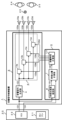
実施の形態1における音響信号制御装置について、図1~図4を用いて説明する。図1は、実施の形態1における音響信号制御装置1の構成を示すブロック図である。
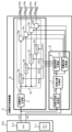
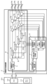
図1において、音響信号制御装置1は、効果音生成部2、音像位置制御部3で構成されている。効果音生成部2は、音響信号生成部4、音響信号制御部5で構成されている。音像位置制御部3は、聴感加速度推定部6、音像位置計算部7、遅延時間計算部8で構成されている。
<構成>
実施の形態1における音響信号制御装置について、図1~図4を用いて説明する。図1は、実施の形態1における音響信号制御装置1の構成を示すブロック図である。
図1において、音響信号制御装置1は、効果音生成部2、音像位置制御部3で構成されている。効果音生成部2は、音響信号生成部4、音響信号制御部5で構成されている。音像位置制御部3は、聴感加速度推定部6、音像位置計算部7、遅延時間計算部8で構成されている。
移動体20は、乗員である運転手24が搭乗し、運転手24の運転若しくは操縦により移動可能な移動体である。移動体20には、乗員として運転手24以外の同乗者25が搭乗していてもよい。移動体20は、例えば、自動車、二輪車、トラック、鉄道、船舶、航空機などである。移動体20は、エンジン21と、それぞれ図示しない操舵機構、車輪などの被駆動装置、電池、燃料などの動力リソースなどを備える。エンジン21は、例えば、ガソリンエンジン、ディーゼルエンジンなどの内燃機、又は電動機などである。エンジン21は、内燃機と電動機とを組み合せたハイブリッド構成であってもよい。
なお、移動体20は、移動体20の動作を模擬する運転シミュレータであってもよい。運転シミュレータは、移動体20の動作として、例えば、移動体20の移動状態若しくは運転状態、エンジンの動作などを模擬する。運転シミュレータは、移動体20の動作を模擬するための、コンピュータなどの制御装置(図示せず)を備える。運転シミュレータは、運転手24に移動体20の移動状態などを体験させるため、スピーカ(図示せず)などの音響装置、ディスプレイ(図示せず)などの表示装置を備えてもよい。運転シミュレータは、実際の移動体と同様に、運転手24が搭乗可能な筐体を備えてもよい。運転シミュレータの制御装置は、エンジン21の動作を模擬するエンジン音を示す模擬エンジン音を、発生させることができる。運転シミュレータの制御装置は、実際の移動体と同様に、運転手24の運転操作に応じて、模擬エンジン音の音量、音質、周波数特性などを、変化させることができる。模擬エンジン音は、エンジン21の代わりに設置された音響装置(例えば、スピーカ)を用いて、運転手24に聴こえるように送出されてもよい。また、模擬エンジン音は、スピーカ23a~23dの内のいずれか1つ又は複数用いて、送出されてもよい。
以降、移動体20は、特に断りが無い限り、移動体20の運転シミュレータを含めるものとして説明する。また、移動体20のエンジン21が発生させたエンジン音は、特に断りが無い限り、移動体20の運転シミュレータが生成した模擬エンジン音を含めるものとして説明する。
効果音生成部2は、エンジン音情報101に基づいて、移動体20が発生させたエンジン音を再現した音響信号である擬似エンジン音102を生成する。そして、効果音生成部2は、後述する複数の遅延時間107と疑似エンジン音102とを用いて複数の効果音103を生成する。複数の効果音103は、効果音103a~103dの全部若しくは一部を表す。なお、効果音103a~103dを個別に説明する必要が無い場合、複数の効果音103として省略する。
音像位置制御部3は、エンジン音情報101と速度情報104とに基づいて、複数の効果音103によって生成された音像26が定位する位置を示す音像位置106を制御する。音像とは、同一の音を複数の方向から人の左右の耳に与えると生じる、聴感上の音源である。運転手24若しくは同乗者25は、音像26を、音像位置106が示す位置に知覚する。
音響信号生成部4は、エンジン音情報101が示す各種情報を用いて、移動体20が発生させたエンジン音を再現した音響信号である疑似エンジン音102を生成する。例えば、疑似エンジン音102は、サンプリング周波数16kHz、振幅分解能16bit、所定のフレーム長(10msec)で区切られたデジタル信号であり、所定のフレーム周期毎に生成される。以降の説明を簡単にするため、フレーム周期を10msecとし、フレーム長と同じ時間長で同期させることとするが、フレーム周期は、10msecに限らない。例えば、フレーム周期を20msecとして、フレーム長(10msec)とは異なる時間長にしてもよい。この場合、例えば、疑似エンジン音102は、同一内容のフレームが2つ連続した2フレーム分のデジタル信号として、生成される。
エンジン音情報101は、移動体20に備えられたエンジン21に関する情報であり、例えば、内燃機若しくは電動機などのエンジンの回転数情報、エンジンの形式情報などである。例えば、エンジン音情報101は、疑似エンジン音102のフレーム周期と同期して、予め定められたフレーム周期毎に取得されてもよいが、エンジン音情報101のフレーム周期はこれに限らない。エンジン音情報101の取得のための周期は、疑似エンジン音102のフレーム周期と同期しなくてもよい。エンジン音情報101は、移動体20の運転シミュレータが発生させる模擬エンジン音に関する情報であってもよい。
エンジンの回転数情報は、例えば、エンジン21の出力軸の所定の時間あたりの回転数、所定の時間あたりの各気筒の爆発回数などである。例えば、エンジンの回転数情報は、エンジン21を制御するECU(Electronic Cotrol Unit)22を介して取得することができる。エンジンの回転数情報は、点火コイルの電気信号又はエンジン21の振動から推定してもよい。また、エンジンの回転数情報は、エンジン21に接続された変速機、ドライブシャフト、ドライブスプロケットの回転数から得られる信号であってもよい。エンジンの回転数情報は、運転シミュレータを制御する制御装置から取得されてもよい。
エンジンの形式情報は、例えば、エンジン21が内燃機の場合、内燃機の形式に関する情報である。例えば、内燃機の形式に関する情報は、シリンダー数、ローター数、シリンダーの配置(直列型、V型、水平対向型など)、点火方法(火花点火、圧縮点火など)、過給機の有無などである。また、エンジンの形式情報は、例えば、エンジン21が電動機の場合、電動機の形式に関する情報である。例えば、電動機の形式に関する情報は、電動機の個数、電動機の出力などである。なお、電動機の形式に関する情報は、模擬する内燃機の形式に関する情報、模擬する移動体の形状若しくは種別の情報(例えば、スポーツカー、SUV(スポーツ多用途車両)、二輪車、バス、トラック、鉄道、船舶、航空機など)が含まれていてもよい。
音響信号生成部4は、エンジン音情報101以外の情報に基づいて、疑似エンジン音102を生成してもよい。例えば、音響信号生成部4は、マイクロホンを用いて、移動体20の車室内若しくはエンジンルーム内のエンジン音をリアルタイムで収録し、収録されたエンジン音を疑似エンジン音102として生成してもよい。あるいは、音響信号生成部4は、予め収録されたエンジン音を加工若しくは修正することで疑似エンジン音102を生成してもよい。また、音響信号生成部4は、例えば、振動ピックアップを用いてエンジン21の振動を検出し、検出されたエンジン21の振動からエンジン音を推定することで、疑似エンジン音102を生成してもよい。なお、疑似エンジン音102は、移動体20の形状に基づいて生成されることが望ましいが、移動体20の形状と疑似エンジン音102の移動体の種類が異なっていてもよい。例えば、移動体20が自動車の場合、疑似エンジン音102を、航空機のエンジン音(例えば、ガスタービンのエンジン音)としてもよい。あるいは、疑似エンジン音102は、例えば、正弦波、矩形波などの信号音から生成されてもよい。
音響信号制御部5は、疑似エンジン音102を、後述する複数の遅延時間107に応じて遅延させることにより、複数の効果音103を生成する。より具体的には、音響信号制御部5は、フィルタ9a~9dを用いて、疑似エンジン音102を、各フィルタに対応した遅延時間107a~107dに応じて遅延させることにより、効果音103a~103dをそれぞれ生成する。例えば、効果音103a~103dのそれぞれのフレーム長は、疑似エンジン音102と同様に、10msecである。
フィルタ9a~9dは、信号の位相を変更するフィルタである。例えば、フィルタ9a~9dは、オールパスフィルタ、位相シフタ、遅延フィルタなどである。
フィルタ9a~9dは、信号の位相を変更するフィルタである。例えば、フィルタ9a~9dは、オールパスフィルタ、位相シフタ、遅延フィルタなどである。
効果音103a~103dは、スピーカ23a~23dを用いて、移動体20に搭乗する運転手24に向けてそれぞれ送出される。なお、運転手24以外の同乗者25が移動体20に搭乗している場合、生成された効果音103a~103dは、同乗者25にも送出されてもよい。
ここで、本実施の形態の音響信号制御装置の特徴である、「聴覚性ベクション」により、移動体20に搭乗する運転手24に移動感を付与させるメカニズムを説明する。
一般に、運転手24がエンジン音を聴くことにより体感する加速度は、運転手24の過去の体験に基づいて想起される、心理的な体感加速度である。具体的には、エンジン回転数の上昇に伴い、エンジン音の音量が増加したり、エンジン音の周波数が高くなったりした場合、運転手24は移動体20が加速しているように感じる。
また、視覚誘導性自己運動感覚(ベクション)という、人の知覚心理に基づく現象が知られている。ベクションとは、広域な視野に一様な方向に動く視覚刺激を提示すると、観察者は、その運動と反対方向に錯覚的に自己身体の移動感覚を覚える現象である。具体的な事例として、観察者が停車中の列車に乗車している際、反対ホーム側の列車が動くのを見ると、観察者は、観察者の列車が動いているような錯覚を覚える。
一般的にベクションというと視覚に関する現象であるが、音を移動させることで聴覚においてもベクションが発生することが知られている。この聴覚におけるベクションを、「聴覚性ベクション」と呼ぶ。本実施の形態では、音像位置制御部3が、疑似エンジン音102の定位位置(すなわち、音像26)を移動させることで、運転手24の「聴覚性ベクション」を誘発する。その結果、移動体20に搭乗している運転手24は、移動体20が加速していると感じる。
一般的にベクションというと視覚に関する現象であるが、音を移動させることで聴覚においてもベクションが発生することが知られている。この聴覚におけるベクションを、「聴覚性ベクション」と呼ぶ。本実施の形態では、音像位置制御部3が、疑似エンジン音102の定位位置(すなわち、音像26)を移動させることで、運転手24の「聴覚性ベクション」を誘発する。その結果、移動体20に搭乗している運転手24は、移動体20が加速していると感じる。
本出願では、運転手24がエンジン音を聴くことにより体感する加速度のうち、運転手24の過去の体験に基づいて想起される心理的な体感加速度を「聴感加速度」と呼び、疑似エンジン音102の移動(すなわち、聴覚性ベクション)により誘発される体感加速度を「聴覚性ベクション加速度」と呼び、区別する。なお、エンジン音は運転手24以外の同乗者25も聴くので、聴感加速度及び聴覚性ベクション加速度の定義に、運転手24以外の同乗者25を含めても構わない。
聴覚性ベクション加速度と聴感加速度とは、両者共に、運転手24がエンジン音を聴くことで体感する加速度であるが、聴覚性ベクション加速度の性質と聴感加速度の性質とは、異なる。聴覚性ベクション加速度は、音像26の「移動」のみにより知覚される。そのため、聴覚性ベクション加速度は、音像を構成している効果音の音質などが問われない。また、聴覚性ベクション加速度は、運転手24が、自身が移動していると錯覚する。そのため、物理的な加速度(加速G)のように、聴覚性ベクション加速度は、実際に移動する加速度に近い性質を有する。よって、聴覚性ベクション加速度は、移動体20の実際の加速度との差を聴感的に補う(演出する)ことができる。言い換えれば、聴覚性ベクション加速度は、移動体20の実際の加速度と、聴感加速度(すなわち、エンジン音による音量増加、回転数上昇などにより体感する心理的な加速度)との差を小さくすることが可能である。このとき、聴感加速度と、移動体20の実際の加速度との加速度の差に応じて聴覚性ベクション加速度を制御することで、聴覚性ベクション加速度を過度に生じさせないようにすることができる。運転手24が体感する加速度の制御を、聴覚性ベクション加速度に基づいて行うことで、運転手24の違和感は、軽減する。その結果、「加速がリニアでない、遅い」などの運転手24の不満は解消する。そして、運転手24は、アクセルを更に開けたりすること無く、運転をスムーズに行うことができる。
また、音像26の位置は、「先行音効果」と呼ばれる心理音響効果により、自在に制御することができる。「先行音効果」とは、例えば、異なる2方向から同じ音を送出した場合、その片方に遅延がある場合、先に耳に届く音の方向からの1つの音に聞こえる現象である。音像26の位置は、「先行音効果」により、複数の異なる方向からの音の到達時間差に応じて、変化する。本実施の形態の音響信号制御装置では、複数の効果音の遅延時間をそれぞれ制御することで、音像26の位置を自在に制御することができる。つまり、音像26の位置の様々な変化を、運転手24に知覚させることができる。
聴感加速度推定部6は、エンジン音情報101を用いて聴感加速度を推定し、聴感加速度の推定値の情報を示す聴感加速度情報105を出力する。聴感加速度情報105は、運転手24以外の同乗者25の聴感加速度の推定値の情報が含まれてもよい。
聴感加速度情報105は、例えば、官能評価実験などにより予め得られたデータを用いて、線形回帰分析による回帰式により求めることができる。式(1)は、回帰式の一例である。式(1)を用いて、エンジン21のエンジン回転数の変化量ΔRから、聴感加速度A’を推定することができる。
聴感加速度情報105は、例えば、官能評価実験などにより予め得られたデータを用いて、線形回帰分析による回帰式により求めることができる。式(1)は、回帰式の一例である。式(1)を用いて、エンジン21のエンジン回転数の変化量ΔRから、聴感加速度A’を推定することができる。

ただし、αとβは、官能評価実験により予め求められた所定の定数である。
音像位置計算部7は、聴感加速度情報105と速度情報104とに基づいて、複数の効果音103により生成される音像であって、運転手24が知覚する音像26の位置を示す音像位置106を計算する。より具体的には、運転手24がエンジン音から体感する聴感加速度A’と、移動体20の実際の加速度Aとに差がある場合、音像26を移動させるように、音像位置106を計算する。
速度情報104は、移動体20の実際の移動速度及び移動方向を示す情報である。例えば、速度情報104は、移動体20が備える車速センサやハンドルの操作舵角からの情報の他、GPS(Global Positioning System)、IMU(Inertial Measurement Unit)、移動体20のECU22などから得ることができる。例えば、速度情報104は、疑似エンジン音102のフレーム周期と同様に、予め定められたフレーム周期毎に取得されてもよいが、疑似エンジン音102のフレーム周期と同期しなくてもよい。
移動体20の実際の加速度Aは、速度情報104を用いて、移動体20の速度の微分、若しくは所定時間あたりの差分から求めることができる。また、移動体20の実際の加速度Aは、移動体20が備える加速度センサから直接求めてもよい。
移動体20の実際の加速度Aは、速度情報104を用いて、移動体20の速度の微分、若しくは所定時間あたりの差分から求めることができる。また、移動体20の実際の加速度Aは、移動体20が備える加速度センサから直接求めてもよい。
遅延時間計算部8は、音像26が定位する位置を示す音像位置106に応じて、複数の遅延時間107を計算する。複数の遅延時間107は、遅延時間107a~107dの全部又は一部である。遅延時間107a~107dの計算方法については、後述する。なお、遅延時間107a~107dを個別に説明する必要が無い場合、複数の遅延時間107として省略する。
図2は、実施の形態1における音響信号制御装置1の具体的な構成を示す一例である。図2の例では、移動体20は自動車である。移動体20には、運転手24と同乗者25とが搭乗している。スピーカ23a~23dは、運転手24と同乗者25とを取り囲むように配置されている。スピーカ23aとスピーカ23bは、運転手24と同乗者25の前方に配置されている。また、スピーカ23cとスピーカ23dは、運転手24と同乗者25の後方に配置されている。
D/A27は、デジタル信号である複数の効果音103をアナログ信号に変換するための、デジタル/アナログ変換装置である。増幅装置28は、例えば、オーディオアンプであり、D/A27から出力された複数の効果音103を増幅する。増幅された複数の効果音103は、それぞれ、スピーカ23a~23dから送出される。そして、効果音103a~103dにより生成された音像26が運転手24に知覚される。
D/A27は、デジタル信号である複数の効果音103をアナログ信号に変換するための、デジタル/アナログ変換装置である。増幅装置28は、例えば、オーディオアンプであり、D/A27から出力された複数の効果音103を増幅する。増幅された複数の効果音103は、それぞれ、スピーカ23a~23dから送出される。そして、効果音103a~103dにより生成された音像26が運転手24に知覚される。
音像位置計算部7は、運転手24が体感する聴感加速度A’と、移動体20の実際の加速度Aとに差がある場合、「聴覚性ベクション」を誘発させるように、音像位置を移動させる。図2に示すように、例えば、移動体20の加速時には、音像26を、運転手24の前方から後方に向かって移動させる(図2中の、矢印”R”)。また、例えば、移動体20の減速時には、音像26を、運転手24の後方から前方に向かって移動させる(図2中の、矢印”F”)。このように、音像26を移動させることにより、運転手24に対して「聴覚性ベクション」を誘発させることができるので、移動体の実際の加速度と、運転手がエンジン音を聴くことにより体感する加速度との差を聴感的に補うことができる。
ここで、現フレームの番号をtとし、現フレームの聴感加速度と、現フレームの移動体20の実際の加速度を、それぞれA’(t)、A(t)とする。音像26が移動する加速度(すなわち、聴覚性ベクション加速度)をa(t)=A’(t)―A(t)と定義し、音像26の移動方向を、移動体20の進行方向のみに限定すると、1フレームあたりの音像26が移動する距離(すなわち、音像の位置の変位量)Δx(t)は、例えば、式(2)で表すことができる。

式(2)において、音像26の現フレームの音像位置(x(t))と、前フレームの音像位置(x(t-1))との差であるΔx(t)は、聴感加速度A’と、移動体20の実際の加速度Aとの差が大きいほど、大きくなる。すなわち、両加速度の差が大きいほど、音像26が移動する距離が大きくなる。なお、式(2)の例は、聴感加速度A’と移動体20の実際の加速度との差を補う場合であるが、これに限らない。例えば、移動体20の実際の加速度Aよりも、音像位置106の移動の加速度a(t)を大きくすることにより、より強い加速感を演出してもよい。
遅延時間計算部8は、音像26が定位する位置を示す音像位置106(x(t))に応じて、複数の遅延時間107を計算する。遅延時間の計算の一例として、図2に示すように、運転手24と同乗者25との中間位置を示す線分CLを定義し、この線分CL上で、音像26を前後に移動させる場合について説明する。中間位置とは、線分CL上の任意の点から運転手25までの距離と、同じ任意の点から同乗者26までの距離とが等距離であることを示す。なお、車室内の音響信号伝達特性(音響空間特性)は、座席や窓ガラスなどによる反射又は回折により影響を受けるが、説明を簡単にするため、車室内を、反射又は回折による影響の無い自由音場として、説明する。
なお、車室内における反射又は回折の影響は、例えば、車室内の音響空間特性の逆特性を有するフィルタにより、軽減することができる。例えば、車室内の音響空間特性は、インパルス応答から得ることができる。具体的には、各スピーカからTSP(Time Stretched Pulse)などの基準信号を送出し、運転手25の位置に設置したマイクロホンを用いて基準信号を取得することで、インパルス応答を得ることができる。そして、インパルス応答から、音響空間特性の逆特性を有するフィルタ係数を算出することができる。こうして得られた逆特性のフィルタ係数を、フィルタ9a~9dのフィルタ係数に加味することで、効果音103a~103dを、反射又は回折の影響が打ち消された信号に補正することができる。
まず、スピーカ23aとスピーカ23bのみを用いて、音像26aを、前部の2つのスピーカ間の中央に定位させる場合について説明する。この場合、スピーカ23aから音像26aまでの距離と、スピーカ23bから音像26aまでの距離は等しくなるため、遅延時間107aと、遅延時間107bとを同一の値とすればよい。そうすることにより、スピーカ23aから送出された効果音103aの音像26aまでの到達時間と、スピーカ23bから送出された効果音103bの音像26aまでの到達時間は同じとなる。したがって、効果音103aと効果音103bとによって生成された音像26aは、前部の2つのスピーカ間の中央に定位することとなる。
次に、スピーカ23cとスピーカ23dのみを用いて、音像26bを、後部の2つのスピーカ間の中央に定位させる場合について説明する。この場合、前部の2つのスピーカの場合と同様に、遅延時間107cと遅延時間107dとを同一の値とすればよい。そうすることにより、スピーカ23cから送出された効果音103cの音像26bまでの到達時間と、スピーカ23dから送出された効果音103dの音像26bまでの到達時間は同じとなる。したがって、効果音103cと効果音103dとによって生成された音像26bは、後部の2つのスピーカ間の中央に定位することとなる。
続いて、スピーカ23a~23dの4つのスピーカを用いて、音像26を、線分CL上で前後に移動させる場合について説明する。遅延時間107a~107dを全て同一の値とすると、スピーカ23a~23dのそれぞれから送出された効果音103a~103dの音像26までの到達時間は全て同じとなる。したがって、音像26は、4つのスピーカの中央位置に定位することとなる。なお、音像26は、見かけ上、音像26aと音像26bとによって生成された音像とみなすことができる。そこで、遅延時間107aと遅延時間107bの組と、遅延時間107cと遅延時間107dの組との間に一定の時間差を与えると、音像26aと音像26bとの間で「先行音効果」が生じる。その結果、時間差に応じて、線分CL上で音像26の位置が変化する。音像26を、4つのスピーカの中央位置より前部に定位させるには、前部スピーカから送出される効果音の到達時間を、後部スピーカからの送出される効果音の到達時間よりも早くする。すなわち、遅延時間107aと遅延時間107bの組の遅延時間を、遅延時間107cと遅延時間107dの組の遅延時間よりも小さくすればよい。また、音像26を、4つのスピーカの中央位置より後部に定位させるには、後部スピーカから送出される効果音の到達時間を、前部スピーカから送出される効果音の到達時間よりも早くする。すなわち、遅延時間107cと遅延時間107dの組の遅延時間を、遅延時間107aと遅延時間107bの組の遅延時間よりも小さくすればよい。つまり、前部と後部のスピーカの間の遅延時間を制御することで、音像26を前後に移動させることが可能である。
以上、音像26を前後方向に移動させる例について説明した。同様な原理を用いることで、音像26を左右方向に移動させることも可能である。具体的には、右側スピーカの遅延時間(すなわち、遅延時間107aと遅延時間107cの組)と、左側スピーカの遅延時間(すなわち、時間107bと遅延時間107dの組)との間に一定の時間差を与えればよい。したがって、複数の効果音の遅延時間をそれぞれ制御することで、音像26の位置を自在に制御することが可能である。
複数の効果音103のそれぞれの到達時間差は、音像位置106が示す現フレームの音像位置(x(t))に応じて定められる。遅延時間計算部8は、定められた到達時間差に従って、効果音103a~103dの遅延時間をそれぞれ計算し、遅延時間107a~107dとしてそれぞれ出力する。
スピーカ23a~23dのそれぞれの設置位置は、図2に例示されるように、運転手24若しくは同乗者25を取り囲むように設置されることが望ましいが、これに限らない。移動体20の室内形状は、移動体の種別に応じて異なるため、スピーカ23a~23dのそれぞれの設置位置は、適宜変更されてもよい。また、スピーカ23a~23dのそれぞれの設置位置の高さは、例えば、運転手24若しくは同乗者25の耳の高さを基準として設置されることが望ましいが、これに限らない。例えば、スピーカ23a~23dは、移動体20の天井、又は、運転手24の足元付近に設置されてもよい。また、スピーカの個数は4個に制限されず、例えば、5個以上であってもよい。なお、スピーカの個数は2個以上であれば、音像位置26の移動は可能であり、例えば、スピーカ23a及びスピーカ23cの2個の構成も可能である。
図2の例では、音像26を運転手24の前後に移動させることで、移動体20の加速感(若しくは減速感)を聴感的に補っているが、これに限らない。例えば、速度情報104に応じて、音像26を、運転手24の右側から左側(若しくは左側から右側)に移動させてもよい。音像26を左右に移動させることで、運転手24に対し、移動体20の旋回感を演出することができ、運転時の満足度を高めることができる。
図2の例では、スピーカ23a~23dは水平に配置されているが、スピーカの配置は水平に限らない。例えば、スピーカ23bを運転手24の頭上位置に配置し、スピーカ23dを運転手24の足元位置に配置するように、スピーカを運転手24の上下位置に配置してもよい。スピーカを運転手24の上下位置に配置することで、音像26を運転手24の上下方向にも移動させることができる。音像26を運転手24の上下方向に移動させることで、例えば、三次元行動可能な移動体(航空機、ドローン、潜水艇など)を運転する際の違和感を軽減することができる。
<ハードウェア>
図1に示される音響信号制御装置1の各構成は、例えば、プロセッサを内蔵する情報処理装置であるコンピュータで実現可能である。図3は、実施の形態1における音響信号制御装置1が有するハードウェアの構成を示す図である。図3において、音響信号制御装置1は、プロセッサ30、メモリ31、記憶装置32、インタフェース33、信号路34とで構成される。
図1に示される音響信号制御装置1の各構成は、例えば、プロセッサを内蔵する情報処理装置であるコンピュータで実現可能である。図3は、実施の形態1における音響信号制御装置1が有するハードウェアの構成を示す図である。図3において、音響信号制御装置1は、プロセッサ30、メモリ31、記憶装置32、インタフェース33、信号路34とで構成される。
プロセッサ30を内蔵するコンピュータは、例えば、機器組み込み用途のマイクロコンピュータ、及びSoC(System on Chip)などである。あるいは、スマートフォン、タブレット型コンピュータなどの可搬型コンピュータなどである。
プロセッサ30は、音響信号制御装置1の全体を制御する。例えば、プロセッサ30は、CPU(Central Processing Unit)、FPGA(Field Programmable Gate Array)、DSP(Digital Signal Processor)などである。プロセッサ30は、単一のプロセッサでもマルチプロセッサでもよい。また、音響信号制御装置1は、コンピュータ以外にASIC(Application Specific Integrated Circuit)などの処理回路を有してもよい。処理回路は、単一回路又は複合回路でもよい。
メモリ31は、音響信号制御装置1の主記憶装置である。例えば、メモリ31は、プロセッサ30の動作に必要なデータを保持する。例えば、メモリ31は、RAM(Random Access Memory)である。
記憶装置32は、音響信号制御装置1の補助記憶装置である。例えば、記憶装置32は、音響信号制御装置1の動作に必要な初期値データ、プログラム、エラーログなどを記憶する。例えば、記憶装置32は、ROM(Read Only Memory)、HDD(Hard Disk Drive)、又はSSD(Solid State Drive)である。
インタフェース33は、音響信号制御装置1に接続される外部装置とデータの送受を行うための、入出力インタフェースである。例えば、インタフェース33は、NIC(Network Interface Controller)などである。例えば、外部装置は、図3の例ではD/A27、ECU22である。インタフェース33は、プロセッサ30に、ECU22から出力されるエンジン音情報101と速度情報104とを入力する。インタフェース33は、D/A27に、プロセッサ30から出力される複数の効果音103を出力する。また、インタフェース33は、音響信号制御装置1の制御に必要な情報と、音響信号制御装置1の制御処理の実行命令とを入力するデバイスでもある。
信号路34は、図3に記された、音響信号制御装置1の各構成要素間でデータ送受信を行うための伝送路(バス)である。
プロセッサ30は、記憶装置32に記憶されている音響信号制御プログラムを、信号路34を通じてメモリ31に読み出す。そして、プロセッサ30が、そのプログラムを実行することで、音響信号制御方法の各処理を実現することができる。記憶装置32は、実施の形態1の音響信号制御方法を実現するためのプログラム及びデータを保持する。なお、音響信号制御プログラムは、インタフェース33を介して、音響信号制御装置1の外部から供給されてもよい。また、音響信号制御プログラムは、コンピュータで読み取り可能な不揮発性記憶媒体(例えば、CD(Compact Disc)、DVD(Digital Versatile Disc)、フラッシュメモリ、など)により提供されてもよい。即ち、音響信号制御プログラムは、例えば、プログラムプロダクトとして提供されてもよい。
なお、音響信号制御装置1は、移動体20に搭載されるが、これに限らない。例えば、移動体20が運転シミュレータの場合、移動体20とは別の場所にあるコンピュータ等により構成されてもよい。この場合、移動体20の各種情報は、例えば、インタフェース33に接続された通信網を介してデータ伝送を行い、上記コンピュータ上の音響信号制御装置1に入力されればよい。また、上記コンピュータ上の音響信号制御装置1で生成された複数の効果音103は、例えば、通信網を介して移動体20のD/A27へ送出されればよい。なお、通信網は、例えば、有線又は無線のネットワークであり、LAN(Local Area Network)などの専用線、インターネットなどである。
<動作>
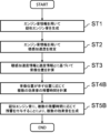
次に、実施の形態1における、音響信号制御装置の動作について説明する。図4は、実施の形態1における音響信号制御装置1の動作を表すフローチャートである。
次に、実施の形態1における、音響信号制御装置の動作について説明する。図4は、実施の形態1における音響信号制御装置1の動作を表すフローチャートである。
ステップST1において、音響信号生成部4が、エンジン音情報101を用いて、疑似エンジン音102を生成する(ステップST1)。
ステップST2において、聴感加速度推定部6が、エンジン音情報101を用いて聴感加速度を推定し、聴感加速度の推定値の情報を示す聴感加速度情報105を出力する(ステップST2)。
ステップST3において、音像位置計算部7が、聴感加速度情報105と速度情報104とに基づいて、複数の効果音103によって生成された音像26であって、運転手24が知覚する音像26の位置を示す音像位置106を計算する(ステップST3)。
ステップST4において、遅延時間計算部8が、音像位置106が示す位置に応じて、複数の遅延時間107を計算する。具体的には、フィルタ9a~9dが出力する効果音103a~103dの遅延時間をそれぞれ計算し、遅延時間107a~107dとしてそれぞれ出力する(ステップST4)。
ステップST5において、音響信号制御部5が、疑似エンジン音102を、複数の遅延時間107に応じて遅延させることにより、複数の効果音103を生成する(ステップST5)。
なお、ステップST1の処理は、ステップST5の処理前に行われていれば良いので、ステップST1の処理は、ステップST2からステップST4までのいずれかの処理の後に行ってもよい。
上記したように、本実施の形態の音響信号制御装置は、エンジン音情報と複数の遅延時間とに基づいて、移動体が発生させたエンジン音を再現した擬似エンジン音を用いて複数の効果音を生成し、エンジン音情報と速度情報とに基づいて、複数の効果音の遅延時間をそれぞれ制御することで、複数の効果音によって生成された音像が定位する位置を示す音像位置を制御するようにした。
よって、本実施の形態の音響信号制御装置は、疑似エンジン音の音像が定位する位置を移動させることで、移動体の実際の加速度と、運転手がエンジン音を聴くことにより体感する加速度との差を聴感的に補うことができるため、運転手が移動体に搭乗して運転する際の違和感を軽減することができる。
よって、本実施の形態の音響信号制御装置は、疑似エンジン音の音像が定位する位置を移動させることで、移動体の実際の加速度と、運転手がエンジン音を聴くことにより体感する加速度との差を聴感的に補うことができるため、運転手が移動体に搭乗して運転する際の違和感を軽減することができる。
実施の形態2.
上述した実施の形態1では、複数の効果音をそれぞれ遅延させることで音像位置を制御しているが、音像位置の制御方法は、遅延に限らない。例えば、複数の効果音の音量をそれぞれ変化させることで、音像位置を制御することが可能である。これを実施の形態2として説明する。
上述した実施の形態1では、複数の効果音をそれぞれ遅延させることで音像位置を制御しているが、音像位置の制御方法は、遅延に限らない。例えば、複数の効果音の音量をそれぞれ変化させることで、音像位置を制御することが可能である。これを実施の形態2として説明する。
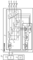
図5は、実施の形態2における音響信号制御装置1の構成を示すブロック図である。図1と比較して新たな構成は、ゲイン計算部10と、ゲイン制御部11a~11dである。その他の構成と動作については図1と同様であり、説明を省略する。
ゲイン計算部10は、音像26が定位する位置を示す音像位置106に応じて、複数の効果音103の音量を示すゲインを計算する。得られたゲインは、複数のゲイン108として出力される。複数のゲイン108は、ゲイン108a~108dの全部又は一部である。なお、ゲイン108a~108dを個別に説明する必要が無い場合、複数のゲイン108として省略する。
ゲイン計算部10で、複数の効果音103の音量の制御によって音像26の位置を変更するためには、一般に「パンニング」と呼ばれる方法を用いることができる。具体的には、図2の例において、音像26を、4つのスピーカの中央位置より前部に定位させるには、前部スピーカから送出される効果音の音量を、後部スピーカから送出される効果音の音量よりも大きくする。すなわち、ゲイン108aとゲイン108bの組のゲイン(すなわち、音量)を、ゲイン108cとゲイン108dの組のゲイン(すなわち、音量)よりも大きくすればよい。また、音像26を、4つのスピーカの中央位置より後部に定位させるには、後部スピーカから送出される効果音の音量を、前部スピーカから送出される効果音の音量よりも大きくする。すなわち、ゲイン108cとゲイン108dの組のゲインを、ゲイン108aとゲイン108bの組のゲインよりも大きくすればよい。したがって、複数の効果音103の音量をそれぞれ制御することで、音像26の位置を自在に制御することが可能である。
音響信号制御部5は、複数のゲイン108に応じて、疑似エンジン音102の音量を制御することにより、複数の効果音103を生成する。より具体的には、音響信号制御部5は、ゲイン制御部11a~11dを用いて、ゲイン108a~108dに応じて疑似エンジン音102の音量を制御することにより、効果音103a~103dをそれぞれ生成する。例えば、ゲイン制御部11a~11dは、増幅装置又は減衰装置など、デジタル信号の振幅を制御する装置である。なお、ゲイン制御部11a~11dは、実施の形態1で示したフィルタ9a~9dと同様、音響空間特性の逆特性を有するフィルタを有していてもよい。
図6は、実施の形態2における音響信号制御装置1の動作を示すフローチャートである。ステップST1からステップST3までの各処理は、実施の形態1の図1で示したのと同様であるので、説明を省略する。
ステップST4Aにおいて、ゲイン計算部10が、音像位置106が示す位置に応じて、複数の効果音103の音量を示す複数のゲイン108を計算する。具体的には、フィルタ9a~9dが出力する効果音103a~103dのゲインをそれぞれ計算し、ゲイン108a~108dとしてそれぞれ出力する(ステップST4A)。
ステップST5Aにおいて、音響信号制御部5が、疑似エンジン音102を、複数のゲイン108に応じて音量を制御することにより、複数の効果音103を生成する(ステップST5A)。
上記したように、本実施の形態の音響信号制御装置は、エンジン音情報と複数の効果音の音量を示すゲインに基づいて、移動体が発生させたエンジン音を再現した擬似エンジン音を用いて複数の効果音を生成し、エンジン音情報と速度情報とに基づいて、複数の効果音のゲインをそれぞれ制御することで、複数の効果音によって生成された音像が定位する位置を示す音像位置を制御するようにした。
よって、本実施の形態の音響信号制御装置は、疑似エンジン音の音像が定位する位置を移動させることで、移動体の実際の加速度と、運転手がエンジン音を聴くことにより体感する加速度との差を聴感的に補うことができるため、運転手が移動体に搭乗して運転する際の違和感を軽減することができる。
よって、本実施の形態の音響信号制御装置は、疑似エンジン音の音像が定位する位置を移動させることで、移動体の実際の加速度と、運転手がエンジン音を聴くことにより体感する加速度との差を聴感的に補うことができるため、運転手が移動体に搭乗して運転する際の違和感を軽減することができる。
実施の形態3.
上述した実施の形態1では、複数の効果音をそれぞれ遅延させることで、音像位置を制御しているが、音像位置の制御方法は、遅延に限らない。例えば、複数の効果音にそれぞれ残響を付与することで、音像位置を制御することが可能である。これを実施の形態3として説明する。
上述した実施の形態1では、複数の効果音をそれぞれ遅延させることで、音像位置を制御しているが、音像位置の制御方法は、遅延に限らない。例えば、複数の効果音にそれぞれ残響を付与することで、音像位置を制御することが可能である。これを実施の形態3として説明する。
図7は、実施の形態3における音響信号制御装置1の構成を示すブロック図である。図1と比較して新たな構成は、残響時間計算部12と、残響制御部13a~13dとである。その他の構成と動作については図1と同様であり、説明を省略する。
残響時間計算部12は、音像26が定位する位置を示す音像位置106に応じて、複数の効果音103の残響が継続する時間を示す残響時間を計算する。得られた残響時間は、複数の残響時間109として出力される。複数の残響時間109は、残響時間109a~109dの全部又は一部である。なお、残響時間109a~109dを個別に説明する必要が無い場合、複数の残響時間109として省略する。
一般に、残響時間が長い音源は、反射又は回折の影響を多く受けているとみなされるため、遠方から到来した音源と知覚される。一方、残響時間が短い音源は、反射又は回折の影響が少ないとみなされるため、近傍の音源と知覚される。この原理を応用し、複数の効果音103の残響時間をそれぞれ制御することにより、音像の位置を制御することが可能である。具体的には、図2の例において、音像26を、4つのスピーカの中央位置より前部に定位させるには、前部スピーカから送出される効果音の残響時間を、後部スピーカから送出される効果音の残響時間よりも小さくする。すなわち、残響時間109aと残響時間109bの組の残響時間を、残響時間109cと残響時間109dの組の残響時間よりも小さくすればよい。また、音像26を、4つのスピーカの中央位置より後部に定位させるには、後部スピーカから送出される効果音の残響時間を、前部スピーカから送出される効果音の残響時間よりも小さくする。すなわち、残響時間109cと残響時間108dの組の残響時間を、残響時間109aと残響時間109bの組の残響時間よりも小さくすればよい。したがって、複数の効果音103の残響時間をそれぞれ制御することで、音像26の位置を自在に制御することが可能である。
音響信号制御部5は、複数の残響時間109に応じて、疑似エンジン音102に残響を付与することにより、複数の効果音103を生成する。より具体的には、音響信号制御部5は、残響制御部13a~13dを用いて、残響時間109a~109dに応じて疑似エンジン音102の残響時間を制御することにより(言い換えれば、残響を付与することにより)、効果音103a~103dをそれぞれ生成する。例えば、残響制御部13a~13dは、コムフィルタなど、残響を生成するフィルタである。なお、残響制御部13a~13dは、実施の形態1で示したフィルタ9a~9dと同様、音響空間特性の逆特性を有するフィルタを有していてもよい。
図8は、実施の形態3における音響信号制御装置1の動作を示すフローチャートである。ステップST1からステップST3までの各処理は、実施の形態1の図1で示したのと同様であるので、説明を省略する。
ステップST4Bにおいて、残響時間計算部12が、音像位置106が示す位置に応じて、複数の効果音103の残響が継続する時間を示す複数の残響時間109を計算する。具体的には、フィルタ9a~9dが出力する効果音103a~103dの残響時間をそれぞれ計算し、残響時間109a~109dとしてそれぞれ出力する(ステップST4B)。
ステップST5Bにおいて、音響信号制御部5が、疑似エンジン音102に、複数の残響時間109に応じて残響を付与することにより、複数の効果音103を生成する(ステップST5B)。
上記したように、本実施の形態の音響信号制御装置は、移動体が発生させたエンジン音を再現した擬似エンジン音を用いて複数の効果音を生成し、エンジン音情報と速度情報とに基づいて、複数の効果音の残響時間をそれぞれ制御することで、複数の効果音によって生成された音像が定位する位置を示す音像位置を制御するようにした。
よって、本実施の形態の音響信号制御装置は、疑似エンジン音の音像が定位する位置を移動させることで、移動体の実際の加速度と、運転手がエンジン音を聴くことにより体感する加速度との差を聴感的に補うことができるため、運転手が移動体に搭乗して運転する際の違和感を軽減することができる。
よって、本実施の形態の音響信号制御装置は、疑似エンジン音の音像が定位する位置を移動させることで、移動体の実際の加速度と、運転手がエンジン音を聴くことにより体感する加速度との差を聴感的に補うことができるため、運転手が移動体に搭乗して運転する際の違和感を軽減することができる。
実施の形態4.
実施の形態1の構成は、実施の形態2の構成と組み合わせることも可能である。具体的には、複数の効果音に対して遅延を生じさせた上、更に、遅延させた複数の効果音の音量を制御することが可能である。これを実施の形態4として説明する。
実施の形態1の構成は、実施の形態2の構成と組み合わせることも可能である。具体的には、複数の効果音に対して遅延を生じさせた上、更に、遅延させた複数の効果音の音量を制御することが可能である。これを実施の形態4として説明する。
図9は、実施の形態4における音響信号制御装置1の構成を示すブロック図である。図1と比較して新たな構成は、ゲイン計算部10と、ゲイン制御部11a~11dとがそれぞれ追加されている。その他の構成と動作については図1と同様であり、説明を省略する。
ゲイン計算部10は、音像26が定位する位置を示す音像位置106に応じて、複数の効果音103の音量を示すゲインを計算する。得られたゲインは、複数のゲイン108として出力される。
音響信号制御部5は、複数のゲイン108に応じて、複数の効果音103の音量をそれぞれ制御する。より具体的には、音響信号制御部5は、ゲイン制御部11a~11dを用いて、ゲイン108a~108dに応じて、効果音103a~103dの音量をそれぞれ制御する。
人は、音源、すなわち、音波を発生させる物体の位置によって左右の耳に生じる音情報の僅かな差を使って、音像位置を知覚する。その際、低域では両耳間時間差(Interaural Time Difference:ITD)が優勢となり、高域では両耳間音圧差(Interraural Level Difference:ILD)が優勢となる。そのため、疑似エンジン音102(すなわち、複数の効果音103)の周波数特性によっては、遅延時間の制御のみ、又は音量の制御のみでは、音像位置106の制御が困難となる場合がある。
また、複数の効果音103の各効果音間の遅延時間の差が大きい場合、具体的には、遅延時間の差が概ね0.04秒を超える場合、複数の効果音は、1つの音像として定位しなくなる。その結果、複数の効果音は、分離してエコーとして知覚されるため、先行音効果が生じなくなる。
そこで、複数の効果音103による音像位置106の制御において、遅延時間の制御とゲインの制御とを組み合わせることで、両者の制御方法の弱点を補うことができ、音像位置106を精度よく制御することができる。
また、複数の効果音103の各効果音間の遅延時間の差が大きい場合、具体的には、遅延時間の差が概ね0.04秒を超える場合、複数の効果音は、1つの音像として定位しなくなる。その結果、複数の効果音は、分離してエコーとして知覚されるため、先行音効果が生じなくなる。
そこで、複数の効果音103による音像位置106の制御において、遅延時間の制御とゲインの制御とを組み合わせることで、両者の制御方法の弱点を補うことができ、音像位置106を精度よく制御することができる。
複数の効果音103の遅延時間とゲインとの制御を組み合わせる方法として、例えば、複数の効果音103の低域成分に関しては、遅延時間による制御を行い、複数の効果音103の高域成分に関しては、ゲインによる制御を行うことで、音像位置106を制御することができる。より具体的には、疑似エンジン音102の所定の閾値未満の低域成分(例えば、2000Hz未満の周波数成分)に関しては、遅延時間計算部8が遅延時間を計算し、疑似エンジン音102の所定の閾値以上の高域成分(例えば、2000Hz以上の周波数成分)に関しては、ゲイン計算部10が、ゲインを計算する。なお、所定の閾値は2000Hzに限らず、別の値にしてもよい。例えば、所定の閾値は、疑似エンジン音102の周波数特性や、移動体の種別などに応じて適宜変更されてもよい。
また、遅延時間とゲインの計算方法については、所定の閾値によらず、例えば、遅延時間とゲインによる音像位置106の制御を、疑似エンジン音102の周波数に応じて按分してもよい。例えば、遅延時間の制御とゲインの制御との割合は、疑似エンジン音102(すなわち、複数の効果音103)の周波数が高くなるにしたがって、ゲインによる制御の割合を増加させてもよい。
また、遅延時間とゲインの計算方法については、所定の閾値によらず、例えば、遅延時間とゲインによる音像位置106の制御を、疑似エンジン音102の周波数に応じて按分してもよい。例えば、遅延時間の制御とゲインの制御との割合は、疑似エンジン音102(すなわち、複数の効果音103)の周波数が高くなるにしたがって、ゲインによる制御の割合を増加させてもよい。
また、複数の効果音103の遅延時間とゲインとの制御を組み合わせる他の方法として、例えば、複数の効果音103の遅延時間が、予め定められた所定の閾値(例えば、0.04秒)を越える場合、当該遅延時間に相当する音量差を、複数の効果音103に生じさせることで、音像位置を制御することができる。より具体的には、音像位置計算部7が音像位置106を計算した結果、所定の遅延時間差を示す閾値を越える場合、遅延時間計算部8の代わりに、ゲイン計算部10は、音像位置106が示す位置に音像26が定位するように、複数のゲイン108を計算する。なお、所定の遅延時間差を示す閾値は、0.04秒に限らず、別の値にしてもよい。例えば、所定の遅延時間差を示す閾値は、移動体の種別や、車室内の広さなどに応じて適宜変更されてもよい。
また、遅延時間とゲインの計算方法については、所定の遅延時間を示す閾値によらず、例えば、遅延時間の長さに応じて按分してもよい。例えば、遅延時間の制御とゲインの制御との割合は、遅延時間が長くなるにしたがって、ゲインによる制御の割合を増加させてもよい。
また、遅延時間とゲインの計算方法については、所定の遅延時間を示す閾値によらず、例えば、遅延時間の長さに応じて按分してもよい。例えば、遅延時間の制御とゲインの制御との割合は、遅延時間が長くなるにしたがって、ゲインによる制御の割合を増加させてもよい。
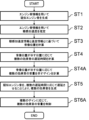
図10は、実施の形態4における音響信号制御装置1の動作を示すフローチャートである。ステップST1からステップST4までの各処理は、実施の形態1の図1で示したのと同様であるので、説明を省略する。
ステップST4Aにおいて、ゲイン計算部10が、音像位置106が示す位置に応じて、複数の効果音103の音量を示す複数のゲイン108を計算する。具体的には、フィルタ9a~9dが出力する効果音103a~103dのゲインをそれぞれ計算し、ゲイン108a~108dとしてそれぞれ出力する(ステップST4A)。
ステップST5において、音響信号制御部5が、疑似エンジン音102を、複数の遅延時間107に応じて遅延させることにより、複数の効果音103を生成する(ステップST5)。
ステップST6Aにおいて、音響信号制御部5が、複数のゲイン108に応じて、複数の効果音103の音量を制御する。より具体的には、音響信号制御部5は、ゲイン制御部11a~11dを用いて、ゲイン108a~108dに応じて効果音103a~103dの音量をそれぞれ制御する(ステップST6A)。
上記したように、本実施の形態の音響信号制御装置は、移動体が発生させたエンジン音を再現した擬似エンジン音を用いて複数の効果音を生成し、エンジン音情報と速度情報とに基づいて、複数の効果音の遅延時間をそれぞれ制御すると共に、複数の効果音のゲインをそれぞれ制御することで、複数の効果音によって生成された音像が定位する位置を示す音像位置を制御するようにした。
よって、本実施の形態の音響信号制御装置は、疑似エンジン音の音像が定位する位置を移動させることで、移動体の実際の加速度と、運転手がエンジン音を聴くことにより体感する加速度との差を聴感的に補うことができるため、運転手が移動体に搭乗して運転する際の違和感を軽減することができる。
よって、本実施の形態の音響信号制御装置は、疑似エンジン音の音像が定位する位置を移動させることで、移動体の実際の加速度と、運転手がエンジン音を聴くことにより体感する加速度との差を聴感的に補うことができるため、運転手が移動体に搭乗して運転する際の違和感を軽減することができる。
更に、本実施の形態の音響信号制御装置は、複数の効果音による音像位置の制御において、遅延時間の制御と音量の制御とを組み合わせているので、両者の制御方法の弱点を補うことができ、音像位置を精度よく制御することができる。
実施の形態5.
実施の形態1の構成は、実施の形態3の構成と組み合わせることも可能である。具体的には、複数の効果音に対して遅延を生じさせた上、更に複数の効果音に残響を付与することが可能である。これを実施の形態5として説明する。
実施の形態1の構成は、実施の形態3の構成と組み合わせることも可能である。具体的には、複数の効果音に対して遅延を生じさせた上、更に複数の効果音に残響を付与することが可能である。これを実施の形態5として説明する。
図11は、実施の形態5における音響信号制御装置1の構成を示すブロック図である。図1と比較して新たな構成は、残響時間計算部12と、残響制御部13a~13dとがそれぞれ追加されている。その他の構成と動作については図1と同様であり、説明を省略する。
残響時間計算部12は、音像26が定位する位置を示す音像位置106に応じて、複数の効果音103の残響が継続する時間を示す残響時間を計算する。得られた残響時間は、複数の残響時間109として出力される。
音響信号制御部5は、複数の残響時間109に応じて、複数の効果音103に残響をそれぞれ付与する。より具体的には、音響信号制御部5は、残響制御部13a~13dを用いて、残響時間109a~109dに応じて、効果音103a~103dの残響時間をそれぞれ制御(残響を付与)する。
図12は、実施の形態5における音響信号制御装置1の動作を示すフローチャートである。ステップST1からステップST4までの各処理は、実施の形態1の図1で示したのと同様であるので、説明を省略する。
ステップST4Bにおいて、残響時間計算部12が、音像位置106が示す位置に応じて、複数の効果音103の残響が継続する時間を示す複数の残響時間109を計算する。具体的には、フィルタ9a~9dが出力する効果音103a~103dの残響時間をそれぞれ計算し、残響時間109a~109dとしてそれぞれ出力する(ステップST4B)。
ステップST5において、音響信号制御部5が、疑似エンジン音102を、複数の遅延時間107に応じて遅延させることにより、複数の効果音103を生成する(ステップST5)。
ステップST6Bにおいて、音響信号制御部5が、複数の残響時間109に応じて、複数の効果音103の残響時間を制御する。より具体的には、音響信号制御部5は、残響制御部13a~13dを用いて、残響時間109a~109dに応じて効果音103a~103dの残響時間をそれぞれ制御する(ステップST6B)。
上記したように、本実施の形態の音響信号制御装置は、移動体が発生させたエンジン音を再現した擬似エンジン音を用いて複数の効果音を生成し、エンジン音情報と速度情報とに基づいて、複数の効果音の遅延時間をそれぞれ制御すると共に、複数の効果音の残響時間をそれぞれ制御することで、複数の効果音によって生成された音像が定位する位置を示す音像位置を制御するようにした。
よって、本実施の形態の音響信号制御装置は、疑似エンジン音の音像が定位する位置を移動させることで、移動体の実際の加速度と、運転手がエンジン音を聴くことにより体感する加速度との差を聴感的に補うことができるため、運転手が移動体に搭乗して運転する際の違和感を軽減することができる。
よって、本実施の形態の音響信号制御装置は、疑似エンジン音の音像が定位する位置を移動させることで、移動体の実際の加速度と、運転手がエンジン音を聴くことにより体感する加速度との差を聴感的に補うことができるため、運転手が移動体に搭乗して運転する際の違和感を軽減することができる。
更に、本実施の形態の音響信号制御装置は、複数の効果音による音像位置の制御において、遅延時間の制御と残響時間の制御とを組み合わせているので、遅延時間による制御の弱点を補うことができ、音像位置を精度よく制御することができる。
実施の形態6.
更に、実施の形態1の構成は、実施の形態2の構成及び実施の形態3の構成と組み合わせることも可能である。具体的には、複数の効果音に対して遅延を生じさせた上、複数の効果音の音量を制御し、複数の効果音に残響を付与することが可能である。これを実施の形態6として説明する。
更に、実施の形態1の構成は、実施の形態2の構成及び実施の形態3の構成と組み合わせることも可能である。具体的には、複数の効果音に対して遅延を生じさせた上、複数の効果音の音量を制御し、複数の効果音に残響を付与することが可能である。これを実施の形態6として説明する。
図13は、実施の形態6における音響信号制御装置1の構成を示すブロック図である。図1と比較して新たな構成は、ゲイン計算部10、ゲイン制御部11a~11d、残響時間計算部12、残響制御部13a~13dが、それぞれ追加されている。その他の構成と動作については図1と同様であり、説明を省略する。
ゲイン計算部10は、音像26が定位する位置を示す音像位置106に応じて、複数の効果音103の音量を示すゲインを計算する。得られたゲインは、複数のゲイン108として出力される。
残響時間計算部12は、音像26が定位する位置を示す音像位置106に応じて、複数の効果音103の残響が継続する時間を示す残響時間を計算する。得られた残響時間は、複数の残響時間109として出力される。
音響信号制御部5は、複数のゲイン108に応じて、複数の効果音103の音量をそれぞれ制御する。より具体的には、音響信号制御部5は、ゲイン制御部11a~11dを用いて、ゲイン108a~108dに応じて、効果音103a~103dの音量をそれぞれ制御する。
更に、音響信号制御部5は、複数の残響時間109に応じて、複数の効果音103に残響をそれぞれ付与する。より具体的には、音響信号制御部5は、残響制御部13a~13dを用いて、残響時間109a~109dに応じて、効果音103a~103dの残響時間をそれぞれ制御(すなわち、残響を付与)する。
図14は、実施の形態6における音響信号制御装置1の動作を示すフローチャートである。ステップST1からステップST4までの各処理は、実施の形態1の図1で示したのと同様であるので、説明を省略する。
ステップST4Aにおいて、ゲイン計算部10が、音像位置106が示す位置に応じて、複数の効果音103の音量を示す複数のゲイン108を計算する。具体的には、フィルタ9a~9dが出力する効果音103a~103dのゲインをそれぞれ計算し、ゲイン108a~108dとしてそれぞれ出力する(ステップST4A)。
ステップST4Bにおいて、残響時間計算部12が、音像位置106が示す位置に応じて、複数の効果音103の残響が継続する時間を示す複数の残響時間109を計算する。具体的には、フィルタ9a~9dが出力する効果音103a~103dの残響時間をそれぞれ計算し、残響時間109a~109dとしてそれぞれ出力する(ステップST4B)。
ステップST5において、音響信号制御部5が、疑似エンジン音102を、複数の遅延時間107に応じて遅延させることにより、複数の効果音103を生成する(ステップST5)。
ステップST6Aにおいて、音響信号制御部5が、複数のゲイン108に応じて、複数の効果音103の音量を制御する。より具体的には、音響信号制御部5は、ゲイン制御部11a~11dを用いて、ゲイン108a~108dに応じて効果音103a~103dの音量をそれぞれ制御する(ステップST6A)。
ステップST6Bにおいて、音響信号制御部5が、複数の残響時間109に応じて、複数の効果音103の残響時間を制御する。より具体的には、音響信号制御部5は、残響制御部13a~13dを用いて、残響時間109a~109dに応じて効果音103a~103dの残響時間をそれぞれ制御する(ステップST6B)。
上記したように、本実施の形態の音響信号制御装置は、移動体が発生させたエンジン音を再現した擬似エンジン音を用いて複数の効果音を生成し、エンジン音情報と速度情報とに基づいて、複数の効果音の遅延時間、複数の効果音の音量、及び複数の効果音の残響時間をそれぞれ制御することで、複数の効果音によって生成された音像が定位する位置を示す音像位置を制御するようにした。
よって、本実施の形態の音響信号制御装置は、疑似エンジン音の音像が定位する位置を移動させることで、移動体の実際の加速度と、運転手がエンジン音を聴くことにより体感する加速度との差を聴感的に補うことができるため、運転手が移動体に搭乗して運転する際の違和感を軽減することができる。
よって、本実施の形態の音響信号制御装置は、疑似エンジン音の音像が定位する位置を移動させることで、移動体の実際の加速度と、運転手がエンジン音を聴くことにより体感する加速度との差を聴感的に補うことができるため、運転手が移動体に搭乗して運転する際の違和感を軽減することができる。
更に、本実施の形態の音響信号制御装置は、複数の効果音による音像位置の制御において、遅延時間による制御と、音量による制御と、残響時間による制御とを組み合わせているので、それぞれの制御の弱点を補うことができ、音像位置を精度よく制御することができる。
実施の形態6では、遅延時間による制御と、音量の制御と、及び残響時間の制御とが行われる場合を説明した。実施の形態6の音響信号制御装置から、遅延時間による制御が省略されてもよく、上記したのと同様の効果を奏する。
以上に説明した各実施の形態における特徴は、互いに適宜組み合わせることができる。
本開示にかかる音響信号制御装置は、例えば、自動車、鉄道、船舶、航空機などの様々な移動体又は移動体のシミュレータに適用可能である。特に、本開示にかかる音響信号制御装置は、運転手が搭乗して運転する移動体や、運転手の運転状態を模擬する移動体の運転シミュレータに用いるのに適している。
1 音響信号制御装置、2 効果音生成部、3 音像位置制御部、4 音響信号生成部、5 音響信号制御部、6 聴感加速度推定部、7 音像位置計算部、8 遅延時間計算部、9a、9b、9c、9d フィルタ、
10 ゲイン計算部、11a、11b、11c、11d ゲイン制御部、
12 残響時間計算部、13a、13b、13c、13d 残響制御部、
20 移動体、21 エンジン、22 ECU、
23a、23b、23c、23d スピーカ、24 運転手、25 同乗者、
26、26a、26b 音像、27 D/A、28 増幅装置、
30 プロセッサ、31 メモリ、32 記憶装置、33 インタフェース、34 信号路。
10 ゲイン計算部、11a、11b、11c、11d ゲイン制御部、
12 残響時間計算部、13a、13b、13c、13d 残響制御部、
20 移動体、21 エンジン、22 ECU、
23a、23b、23c、23d スピーカ、24 運転手、25 同乗者、
26、26a、26b 音像、27 D/A、28 増幅装置、
30 プロセッサ、31 メモリ、32 記憶装置、33 インタフェース、34 信号路。
Claims (10)
- 移動体又は当該移動体の動作を模擬するシミュレータが発生させたエンジン音を再現した音響信号である擬似エンジン音を用いて、複数の効果音を生成する効果音生成部と、
前記移動体又は前記シミュレータの加速度と、前記移動体又は前記シミュレータの乗員が前記エンジン音を聴くことにより体感する加速度である聴感加速度の推定値とに基づいて、前記複数の効果音の音像が定位する位置である音像位置を制御する音像位置制御部と
を有する音響信号制御装置。 - 遅延時間計算部を更に有し、
前記遅延時間計算部は、前記移動体又は前記シミュレータの加速度と前記聴感加速度の推定値とに基づいて、前記複数の効果音の遅延時間を計算し、
前記音像位置制御部は、前記遅延時間に応じて前記音像位置を制御すること
を特徴とする請求項1に記載の音響信号制御装置。 - ゲイン計算部を更に有し、
前記ゲイン計算部は、前記移動体又は前記シミュレータの加速度と前記聴感加速度の推定値とに基づいて、前記複数の効果音の音量を示すゲインを計算し、
前記音像位置制御部は、前記ゲインに応じて前記音像位置を制御すること
を特徴とする請求項1に記載の音響信号制御装置。 - 残響時間計算部を更に有し、
前記残響時間計算部は、前記移動体又は前記シミュレータの加速度と前記聴感加速度の推定値とに基づいて、前記複数の効果音の残響時間を計算し、
前記音像位置制御部は、前記残響時間に応じて前記音像位置を制御すること
を特徴とする請求項1に記載の音響信号制御装置。 - 遅延時間計算部と、ゲイン計算部とを更に有し、
前記遅延時間計算部は、前記移動体又は前記シミュレータの加速度と前記聴感加速度の推定値とに基づいて、前記複数の効果音の遅延時間を計算すると共に、
前記ゲイン計算部は、前記移動体又は前記シミュレータの加速度と前記聴感加速度の推定値とに基づいて、前記複数の効果音の音量を示すゲインを計算し、
前記音像位置制御部は、前記遅延時間及び前記ゲインに応じて、前記音像位置を制御すること
を特徴とする請求項1に記載の音響信号制御装置。 - 前記音像位置制御部は、前記複数の効果音の低域成分の遅延時間を制御すると共に、
前記複数の効果音の高域成分の音量を示すゲインを制御することで、前記音像位置を制御すること
を特徴とする請求項5に記載の音響信号制御装置。 - 前記音像位置制御部は、前記遅延時間が予め定められた所定の閾値未満の場合、前記遅延時間に応じて前記音像位置を制御し、
前記遅延時間が前記閾値以上の場合、前記ゲインに応じて前記音像位置を制御すること
を特徴とする請求項5に記載の音響信号制御装置。 - 前記音像位置制御部は、前記複数の効果音の周波数が高くなるにしたがって、前記ゲインによる制御の割合を増加させることで、音像前記位置を制御すること
を特徴とする請求項5に記載の音響信号制御装置。 - 前記音像位置制御部は、前記複数の効果音の遅延時間が長くなるにしたがって、前記ゲインによる制御の割合を増加させることで、音像前記位置を制御すること
を特徴とする請求項5に記載の音響信号制御装置。 - 効果音生成部が、移動体又は当該移動体の動作を模擬するシミュレータが発生させたエンジン音を再現した音響信号である擬似エンジン音を用いて、複数の効果音を生成し、
音像位置制御部が、前記移動体又は前記シミュレータの加速度と、前記移動体又は前記シミュレータの乗員が前記エンジン音を聴くことにより体感する加速度である聴感加速度の推定値とに基づいて、前記複数の効果音の音像が定位する位置である音像位置を制御する
音響信号制御方法。
Priority Applications (3)
| Application Number | Priority Date | Filing Date | Title |
|---|---|---|---|
| PCT/JP2023/021112 WO2024252546A1 (ja) | 2023-06-07 | 2023-06-07 | 音響信号制御装置及び方法 |
| DE112023005874.1T DE112023005874T5 (de) | 2023-06-07 | 2023-06-07 | Vorrichtung und Verfahren zur Steuerung eines Schallsignals |
| JP2025525514A JP7728491B2 (ja) | 2023-06-07 | 2023-06-07 | 音響信号制御装置及び方法 |
Applications Claiming Priority (1)
| Application Number | Priority Date | Filing Date | Title |
|---|---|---|---|
| PCT/JP2023/021112 WO2024252546A1 (ja) | 2023-06-07 | 2023-06-07 | 音響信号制御装置及び方法 |
Publications (1)
| Publication Number | Publication Date |
|---|---|
| WO2024252546A1 true WO2024252546A1 (ja) | 2024-12-12 |
Family
ID=93795548
Family Applications (1)
| Application Number | Title | Priority Date | Filing Date |
|---|---|---|---|
| PCT/JP2023/021112 Ceased WO2024252546A1 (ja) | 2023-06-07 | 2023-06-07 | 音響信号制御装置及び方法 |
Country Status (3)
| Country | Link |
|---|---|
| JP (1) | JP7728491B2 (ja) |
| DE (1) | DE112023005874T5 (ja) |
| WO (1) | WO2024252546A1 (ja) |
Citations (3)
| Publication number | Priority date | Publication date | Assignee | Title |
|---|---|---|---|---|
| JP2022155835A (ja) * | 2021-03-31 | 2022-10-14 | マツダ株式会社 | 車両用音生成装置 |
| JP2022155833A (ja) * | 2021-03-31 | 2022-10-14 | マツダ株式会社 | 車両用音生成装置 |
| JP2022170271A (ja) * | 2021-04-28 | 2022-11-10 | ヤマハ株式会社 | 音像制御装置および音像制御方法 |
-
2023
- 2023-06-07 DE DE112023005874.1T patent/DE112023005874T5/de active Pending
- 2023-06-07 JP JP2025525514A patent/JP7728491B2/ja active Active
- 2023-06-07 WO PCT/JP2023/021112 patent/WO2024252546A1/ja not_active Ceased
Patent Citations (3)
| Publication number | Priority date | Publication date | Assignee | Title |
|---|---|---|---|---|
| JP2022155835A (ja) * | 2021-03-31 | 2022-10-14 | マツダ株式会社 | 車両用音生成装置 |
| JP2022155833A (ja) * | 2021-03-31 | 2022-10-14 | マツダ株式会社 | 車両用音生成装置 |
| JP2022170271A (ja) * | 2021-04-28 | 2022-11-10 | ヤマハ株式会社 | 音像制御装置および音像制御方法 |
Also Published As
| Publication number | Publication date |
|---|---|
| JPWO2024252546A1 (ja) | 2024-12-12 |
| JP7728491B2 (ja) | 2025-08-22 |
| DE112023005874T5 (de) | 2025-12-24 |
Similar Documents
| Publication | Publication Date | Title |
|---|---|---|
| JP7785729B2 (ja) | アクティブノイズ管理システムのための仮想テスト環境 | |
| CN113050913A (zh) | 用于提供自然声音的系统和方法 | |
| CN113060153B (zh) | 用于调整活动控制参数的系统和方法 | |
| US12192733B2 (en) | Method for audio processing | |
| Greenberg et al. | Physical fidelity of driving simulators | |
| JP2020174346A5 (ja) | ||
| US20230144723A1 (en) | Battery electric vehicle active sound and vibration enhancement systems | |
| EP3358862A1 (en) | Method and device for stereophonic depiction of virtual noise sources in a vehicle | |
| CN116264042A (zh) | 用于改善沉浸感的虚拟驾驶模拟装置及其方法 | |
| Genuit et al. | A virtual car: Prediction of sound and vibration in an interactive simulation environment | |
| JP7728491B2 (ja) | 音響信号制御装置及び方法 | |
| Krebber et al. | Auditory virtual environments: basics and applications for interactive simulations | |
| Genuit et al. | Prediction of sound and vibration in a virtual automobile | |
| Blommer et al. | Realistic 3d sound simulation in the virttex driving simulator | |
| JP2013020033A (ja) | 車室内の音の官能評価装置 | |
| Sottek et al. | Tools and methods for product sound design of vehicles | |
| CN114584911A (zh) | 功放调试方法、声音生成方法及装置、设备和介质 | |
| WO2023086308A1 (en) | Battery electric vehicle active sound and vibration enhancement systems | |
| WO2023086310A1 (en) | Active sound and vibration enhancement systems for battery electric vehicle | |
| JP2004180800A (ja) | 電気レーシングカートシステム及びサーキットシステム | |
| Philippen | Driving Sound Simulator–a Universal Tool in the Development Process | |
| JP4515321B2 (ja) | エンジン音合成装置およびそれを備えた車両、ならびにエンジン音合成方法 | |
| Liu et al. | A Study on Active Sound Design and Control Method for Vehicle Interior Hybrid Noise to Enhance Sound Quality | |
| Riemann et al. | Interactive auralization of powertrain sounds using measured and simulated excitation | |
| Koch et al. | Real-Time Capable Wind and Rolling Noise Synthesis for a More Realistic Vehicle Simulator Experience |
Legal Events
| Date | Code | Title | Description |
|---|---|---|---|
| 121 | Ep: the epo has been informed by wipo that ep was designated in this application |
Ref document number: 23940651 Country of ref document: EP Kind code of ref document: A1 |
|
| WWE | Wipo information: entry into national phase |
Ref document number: 2025525514 Country of ref document: JP |
|
| WWE | Wipo information: entry into national phase |
Ref document number: 112023005874 Country of ref document: DE |
|
| WWP | Wipo information: published in national office |
Ref document number: 112023005874 Country of ref document: DE |