WO2024252448A1 - 経路探索方法、経路探索プログラム及び経路探索装置 - Google Patents
経路探索方法、経路探索プログラム及び経路探索装置 Download PDFInfo
- Publication number
- WO2024252448A1 WO2024252448A1 PCT/JP2023/020765 JP2023020765W WO2024252448A1 WO 2024252448 A1 WO2024252448 A1 WO 2024252448A1 JP 2023020765 W JP2023020765 W JP 2023020765W WO 2024252448 A1 WO2024252448 A1 WO 2024252448A1
- Authority
- WO
- WIPO (PCT)
- Prior art keywords
- point
- information
- distance
- nodes
- area
- Prior art date
- Legal status (The legal status is an assumption and is not a legal conclusion. Google has not performed a legal analysis and makes no representation as to the accuracy of the status listed.)
- Ceased
Links
Images








Classifications
-
- G—PHYSICS
- G01—MEASURING; TESTING
- G01C—MEASURING DISTANCES, LEVELS OR BEARINGS; SURVEYING; NAVIGATION; GYROSCOPIC INSTRUMENTS; PHOTOGRAMMETRY OR VIDEOGRAMMETRY
- G01C21/00—Navigation; Navigational instruments not provided for in groups G01C1/00 - G01C19/00
- G01C21/26—Navigation; Navigational instruments not provided for in groups G01C1/00 - G01C19/00 specially adapted for navigation in a road network
- G01C21/34—Route searching; Route guidance
Definitions
- the present invention relates to a route search method, a route search program, and a route search device.
- picking work which involves taking out items such as cargo or merchandise from a warehouse, has been carried out for some time.
- work efficiency can be improved by moving a worker or a mobile object such as a robot or drone along the shortest route when moving the object to the storage location where each item is stored.
- Dynamic programming which solves the traveling salesman problem, is known as a method for searching for the shortest route.
- dynamic programming the distance between picking points (between storage locations) is used, but calculating the shortest distance between picking points is also an optimization problem, and shortest route derivation algorithms (for example, Dijkstra's algorithm and Bellman-Ford algorithm) are known as solutions to this problem.
- JP 2021-184210 A Japanese Unexamined Patent Publication No. 4-319986
- the present invention aims to provide a route search method, a route search program, and a route search device that can reduce the processing load during route search.
- the route search method receives location information of an impassable area and information on a travel line passing through multiple points set in areas other than the impassable area, sets the intersections of each of the multiple line segments included in the travel line and the intersections obtained by extending the multiple line segments to a range where they do not intersect with the impassable area as nodes, stores information on the distance between the set nodes in a storage unit, and upon receiving information on a first point and a second point among the multiple points, obtains information on the distance between the first point and a first node connected to the first point by the travel line without passing through other nodes, and the distance between the second point and a second node connected to the second point by the travel line without passing through other nodes, and calculates the shortest route from the first point to the second point using a shortest route derivation algorithm using the distance information obtained in the obtaining process and the distance information between the nodes stored in the storage unit.
- FIG. 1 is a diagram illustrating a schematic configuration of a picking system according to a first embodiment.
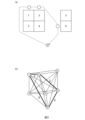
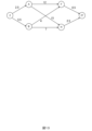
- 2A and 2B are diagrams for explaining an outline of the processing of the server.
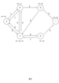
- FIG. 3 is a diagram (graph structure) for explaining the Dijkstra algorithm.
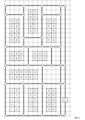
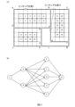
- FIG. 4 is a diagram showing shelves installed in a warehouse.
- FIG. 5A is a diagram showing a route along which traffic occurs within a warehouse
- FIG. 5B is a diagram showing nodes that are set in the first embodiment.
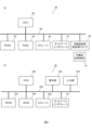
- FIG. 6(a) is a diagram showing the hardware configuration of a server
- FIG. 6(b) is a diagram showing the hardware configuration of a user terminal.
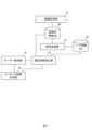
- FIG. 7 is a functional block diagram of the server.
- FIG. 1 is a diagram illustrating a schematic configuration of a picking system according to a first embodiment.
- 2A and 2B are diagrams for explaining an outline of the processing of the server.
- FIG. 3 is a diagram (graph structure) for explaining the Dijkstra algorithm.
- FIG. 8(a) is a diagram showing nodes A to M and picking positions 1, 18, and 27, and FIG. 8(b) is a diagram showing a node information DB.
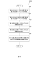
- FIG. 9 is a flowchart showing the advance preparation process in the first embodiment.
- FIG. 10 is a flowchart showing the picking route creation process in the first embodiment.
- FIG. 11 is a flowchart showing the process of step S36 in FIG.
- FIG. 12 is a diagram for explaining the process of calculating the shortest route between picking position 2 and picking position 27.
- FIG. 13 is a diagram showing a graph structure used in the example of FIG.
- FIG. 14 is a diagram for explaining a modification of the first embodiment.
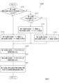
- FIG. 15 is a flowchart showing the advance preparation process in the second embodiment.
- FIG. 16(a) and 16(b) are diagrams for explaining the process of step S15 in FIG. 15.
- FIG. 17A and 17B are diagrams for explaining distance information stored in the node information DB in the second embodiment.
- FIG. 18 is a flowchart showing the process of identifying the shortest path for each combination (step S36').
- FIG. 19 is a flowchart showing the process of step S154 in FIG.
- FIG. 20 is a flowchart showing the process of step S156 in FIG.
- FIG. 21A is a diagram for explaining steps S174 and S176 in FIG. 20
- FIG. 21B is a diagram showing the graph structure used in step S174.
- FIG. 22 is a diagram for explaining a modified example of the second embodiment.
- FIG. 1 shows the configuration of a picking system 100 according to the first embodiment.
- the picking system 100 is a system used in a warehouse.
- the picking system 100 includes a server 10, a user terminal 70, and a robot 60.
- the server 10, the user terminal 70, and the robot 60 are connected to a network 80 such as the Internet or a LAN (Local Area Network).
- a network 80 such as the Internet or a LAN (Local Area Network).
- the server 10 is an information processing device that acquires information within the warehouse (shelf layout information and information on traffic routes) and determines the route (picking route) to take when patrolling the shelves to pick up the items specified in the order.
- the area in which the shelves exist is an area that cannot be passed by people or robots, so the shelf layout information can be said to be location information for impassable areas.
- the user terminal 70 transmits information about the inside of the warehouse to the server 10, and transmits a list of items to be picked in the warehouse (order information). The user terminal 70 also obtains and displays information about the picking route determined by the server 10.
- the robot 60 acquires information about the picking route determined by the server 10, and travels around the warehouse along the picking route to pick up the items specified in the order from the shelves.
- the server 10 uses dynamic programming to solve the traveling salesman problem. For example, as shown in FIG. 2(a), assume that there are shelves 1 to 6 in the warehouse, the shelves indicated in the order are 1, 2, and 6, and the start and end points of the tour are point S. In this case, as shown in FIG. 2(b), the server 10 determines the route that visits shelves 1, 2, and 6 with the smallest total travel cost, based on the travel cost (e.g., distance) between each point, with point S as the start and end points. Note that in FIG. 2(b), the route with the smallest total travel cost is shown in bold, and the travel cost between each point included in that route is shown with underlined numbers.
- the travel cost e.g., distance
- the server 10 needs to find the shortest distance between each point as the distance between each point, and a shortest path derivation algorithm (such as the Dijkstra algorithm or the Bellman-Ford algorithm) is known as a method for doing this.
- a shortest path derivation algorithm such as the Dijkstra algorithm or the Bellman-Ford algorithm
- the case where the Dijkstra algorithm is used will be described, but other shortest path derivation algorithms such as the Bellman-Ford algorithm may also be used.
- Fig. 3 is a diagram (graph structure) for explaining the Dijkstra algorithm.
- the example in Fig. 3 shows a case where the shortest path between point S and point 1 in Fig. 2(b) is found, and points A, B, C, and D are assumed to exist between point S and point 1.
- the distance to all points is assumed to be infinity.
- the distance to point S is set to 0 (see " ⁇ 0" written near point S).
- the point (point S) with the smallest distance is selected, and the distance (0) is determined as the minimum distance of that point.
- each shelf when there is a traffic line near a shelf as shown in FIG. 5(a), the white and black circles shown in FIG. 5(b) are set as nodes.
- the intersections of the line segments included in the traffic line (see white circles) and the intersections obtained by extending the line segments to a range that does not intersect with the shelves (see black circles) are set as nodes.
- FIG. 6A shows the hardware configuration of the server 10.
- the server 10 includes a central processing unit (CPU) 90, a read only memory (ROM) 92, a random access memory (RAM) 94, a storage (e.g., a solid state drive (SSD) or a hard disk drive (HDD)) 96, a network interface 97, and a portable storage medium drive 99.
- CPU central processing unit
- ROM read only memory
- RAM random access memory
- storage e.g., a solid state drive (SSD) or a hard disk drive (HDD)
- the CPU 90 executes a program (including a route search program) stored in the ROM 92 or the storage 96, or a program read from the portable storage medium 91 by the portable storage medium drive 99, thereby realizing the functions of the components shown in FIG. 7.
- the functions of FIG. 7 may be realized by an integrated circuit such as an application specific integrated circuit (ASIC) or a field programmable gate array (FPGA).
- ASIC application specific integrated circuit
- FPGA field programmable gate array
- FIG. 7 shows a functional block diagram of the server 10.
- the CPU 90 executes a program to function as an information acquisition unit 12, advance preparation unit 14, order acquisition unit 16, shortest path calculation unit 18, and picking path creation unit 20.
- FIG. 7 also shows a warehouse information DB 30 stored in the RAM 94, storage 96, etc., and a node information DB 32 as a memory unit.
- the information acquisition unit 12 acquires information about the warehouse (shelf layout information and traffic line information) that is input to the user terminal 70 and transmitted to the server 10, and stores it in the warehouse information DB 30.
- the warehouse information DB 30 stores information about which shelf is located at which position on the grid (the grid indicated by the dashed lines) and the start and end of each line segment of the traffic line.
- the advance preparation unit 14 sets the intersections (white circles) of the line segments included in the traffic line as nodes, as shown in FIG. 5(b), based on the information inside the warehouse as shown in FIG. 5(a).
- the advance preparation unit 14 also sets the intersections (black circles) obtained by extending the line segments of the traffic line so that they do not intersect with the shelves as nodes.
- each node is assigned the symbols A to M as shown in FIG. 8(a) as identification information.
- the advance preparation unit 14 calculates the distance between nodes for each combination of nodes and stores the distance in the node information DB 32.
- the left column in Fig. 8(b) stores information such as the distance between nodes A and B is 8, the distance between nodes A and C is 12, ..., and the distance between nodes L and M is 4.
- the advance preparation unit 14 identifies the picking position of the shelves in the warehouse (the position on the moving path facing each shelf) and calculates the distance between the two nodes (hereinafter referred to as "nearby nodes") that can be directly moved from the picking position along the moving path.
- “nodes that can be directly moved from the picking position along the moving path” means nodes that can be moved from the picking position along the moving path without passing through other nodes.
- the advance preparation unit 14 then stores the calculated distance in the right column of the node information DB 32 in FIG. 8(b). For example, for picking position 1, the nearby nodes are nodes A and B, and for picking position 7, the nearby nodes are nodes D and E. For picking position 27, the nearby nodes are nodes F and H.
- the right column of FIG. 8(b) stores information that the distance between picking position 1 and node A is 1.5, and the distance between picking position 1 and node B is 6.5. Also, information is stored that the distance between picking position 27 and node F is 0.5, and the distance between picking position 27 and node H is 2.5. Note that the travel path can be said to be a line of movement that passes through multiple picking positions (multiple points).
- the order acquisition unit 16 acquires the order information.
- the order information includes the picking start position, information about the shelves to be patrolled (picking positions), and information about the picking end position.
- the order information also includes a request to create an optimal (shortest) picking route (patrol route).
- the shortest path calculation unit 18 calculates the shortest path for each combination of two positions obtained from the picking start position, picking position, and picking end position.
- the picking route creation unit 20 creates an optimal (shortest) picking route based on the shortest route (shortest distance) for each combination of two locations, and outputs the created picking route to the user terminal 70 and the robot 60.
- the user terminal 70 is a terminal (such as a smartphone or tablet terminal) used by a warehouse manager or worker (hereinafter referred to as "user").
- the user inputs warehouse information and order information into the user terminal 70 and transmits the input information to the server 10.
- the user terminal 70 receives and displays information on a picking route created by the server 10 based on the order information.
- FIG. 6(b) shows the hardware configuration of the user terminal 70.
- the user terminal 70 is equipped with a CPU 190, ROM 192, RAM 194, storage 196, network interface 197, display unit 193, input unit 195, etc.
- the display unit 193 includes an LCD display, etc.
- the input unit 195 includes a keyboard, mouse, touch panel, etc.
- the robot 60 is an autonomous mobile robot (AMR) that travels autonomously.
- AMR autonomous mobile robot
- the robot 60 receives picking route information from the server 10
- the robot 60 moves along the picking route and picks up an object such as a product from a shelf.
- Figure 9 is a flowchart showing the advance preparation processing
- Figure 10 is a flowchart showing the picking route creation processing. Each processing will be described below.
- step S10 the information acquisition unit 12 waits until information on the shelf layout and traffic lines within the warehouse is input.
- step S12 the information acquisition unit 12 acquires the input information and stores it in the warehouse information DB 30.
- the shelf layout information and traffic line information as shown in FIG. 5(a) is input.
- step S14 the advance preparation unit 14 sets nodes. Specifically, as shown in FIG. 5(b), the advance preparation unit 14 sets the intersections (white circles) of the line segments included in the travel path as nodes, and also sets the intersections (black circles) obtained by extending the line segments to a range that does not intersect with the shelves as nodes.
- the 13 nodes set in FIG. 5(b) are denoted as nodes A, B, ..., M (see FIG. 8(a)).
- step S16 the advance preparation unit 14 calculates the distance between each node.
- the advance preparation unit 14 stores the calculated distance between each node in the left column of the node information DB 32 shown in FIG. 8(b).
- step S18 the advance preparation unit 14 calculates the distance between each picking position and a nearby node.
- the advance preparation unit 14 stores the calculated distance between each picking position and a nearby node in the right column of the node information DB 32 shown in FIG. 8(b).
- step S30 the order acquisition unit 16 waits until order information is input from the user terminal 70.
- step S32 the order acquisition unit 16 acquires the input order information.
- the order information includes information on the picking start position, one or more picking positions, and the picking end position.
- the order acquisition unit 16 transmits the acquired order information to the shortest path calculation unit 18.
- step S34 the shortest path calculation unit 18 identifies all possible combinations of two positions from the picking start position, one or more picking positions, and the picking end position.
- step S36 the shortest path calculation unit 18 executes a process to identify the shortest path for each combination.
- the process is performed according to the flowchart in FIG. 11.
- step S50 the shortest path calculation unit 18 selects one unselected combination from the combinations identified in step S34. For example, it is assumed that the shortest path calculation unit 18 selects the combination of picking position 2 and picking position 27 shown in FIG. 12. In the following, a process is performed to identify the path (shortest path) that provides the shortest distance between picking positions 2 and 27. In this case, it can be said that picking position 2 is the first point (first position) and picking position 27 is the second point (second position).
- step S52 the shortest path calculation unit 18 identifies nearby nodes (two nodes) of one position (first position) of the combination.
- node A and node B are identified as nearby nodes of picking position 2.
- step S54 the shortest path calculation unit 18 identifies nearby nodes (two nodes) of the other position (second position) of the combination.
- node F and node H are identified as nearby nodes of picking position 27.
- step S56 the shortest path calculation unit 18 reads out the distance between the first position (picking position 2) and each of the nearby nodes (nodes A and B) from the node information DB 32.
- step S58 the shortest path calculation unit 18 reads out the distance between the second position (picking position 27) and each of the nearby nodes (nodes F and H).
- the shortest path calculation unit 18 reads out, from the right column of the node information DB 32 in FIG. 8(b), that the distance between picking position 27 and node F is 0.5, and the distance between picking position 27 and node H is 2.5.
- Fig. 13 is a diagram showing the path from picking position 2 to picking position 27 in a graph structure. Fig. 13 includes the following paths. (2 ⁇ A)+(A ⁇ F)+(F ⁇ 27) (2 ⁇ A)+(A ⁇ H)+(H ⁇ 27) (2 ⁇ B)+(B ⁇ F)+(F ⁇ 27) (2 ⁇ B)+(B ⁇ H)+(H ⁇ 27)
- step S62 the shortest path calculation unit 18 determines whether all combinations have been selected. If the determination in step S62 is negative, the process returns to step S50. Thereafter, the processes and determinations in steps S50 to S62 are repeated until the shortest paths for all combinations have been identified. Then, when the shortest paths for all combinations have been identified and the determination in step S62 is positive, the entire process in FIG. 11 is terminated and the process moves to step S38 in FIG. 10.
- the picking route creation unit 20 uses the distance of the shortest route (shortest distance) for each combination of locations identified in step S36 to create an optimal picking route by dynamic programming that solves the traveling salesman problem.
- the picking route creation unit 20 creates the shortest route that allows the ordered items to be picked up in order as the optimal picking route.
- step S40 the picking path creation unit 20 transmits the created optimal picking path to the user terminal 70 and the robot 60. This allows the user to pick along the picking path displayed on the user terminal 70. Also, the robot 60 can automatically pick along the received picking path. With this, the entire process in FIG. 10 is completed.
- the server 10 receives information on the arrangement of shelves in a warehouse and information on a route that passes through multiple picking positions (S12 in FIG. 9).
- the server 10 also sets the intersections of the multiple line segments included in the route and the intersections obtained by extending the multiple line segments to a range that does not intersect with the shelves as nodes, and stores information on the distance between the set nodes in the node information DB 32 (S14 in FIG. 9).
- the server 10 also selects a combination of positions (first position, second position) (S50 in FIG. 11) and reads the distance between the first position and its neighboring node from the node information DB 32 (S56 in FIG. 11).
- the server 10 also reads the distance between the second position and its neighboring node from the node information DB 32 (S58 in FIG. 11). Then, the server 10 uses each of the read distances and the distances between nodes stored in the node information DB 32 to identify the shortest route from the first position to the second position by Dijkstra's algorithm (S60). This makes it possible to reduce the scale of the graph structure when identifying the shortest route from the first position to the second position, compared to when all picking positions are set as nodes. Therefore, the amount of calculations required when the server 10 identifies the shortest route from the first position to the second position can be reduced. Also, the amount of information stored in the node information DB 32 can be reduced, compared to when all picking positions are set as nodes.
- the picking positions there are 30 picking positions, and the picking positions are set as nodes.
- the graph structure may become large-scale.
- the intersections of the line segments included in the travel path and the intersections (A to M) obtained by extending the line segments are set as nodes, the number of nodes will be 13.
- each picking position is set as a node.
- the graph structure may become very large.
- the points indicated by white circles in FIG. 14 as nodes, the number of nodes becomes 33.
- the size of the graph structure used in the Dijkstra algorithm is reduced by about 61.2% compared to the case where the picking positions are set as nodes. Furthermore, since the amount of distance information that needs to be prepared in advance is reduced, it is possible to reduce the burden on the storage 96. Specifically, the amount of memory is reduced by approximately 80.5% compared to the case where the picking positions are set as nodes.
- the shortest path calculation unit 18 may calculate the distance between the picking position and the nearby node each time it becomes necessary.
- Second Embodiment The second embodiment will be described below. Note that the configuration of the picking system 100 and the configuration of the server 10 are similar to those of the first embodiment (FIGS. 1 and 7, etc.), and therefore the description thereof will be omitted.
- the server 10 treats an area surrounded by a traffic line and that does not include shelves within as an area (free passage area) through which people and robots can pass (cross) freely.
- the processing of the server 10 according to this second embodiment will be described in detail below with reference to the flowcharts in Figs. 15 and 18 to 20, and other drawings as appropriate.
- Fig. 15 is a flowchart of the advance preparation process by the server 10.
- a "free passage area setting process (step S15)" is executed between step S14 and step S16.
- step S12 the information acquisition unit 12 acquires shelf layout information and travel route information (see FIG. 5(a)).
- step S14 the advance preparation unit 14 sets nodes A to M as shown in FIG. 8(a).
- step S15 the advance preparation unit 14 sets a free passage area in the warehouse of FIG. 8(a).
- the advance preparation unit 14 identifies areas that do not include shelves within a triangular area with three nodes as vertices. As a result, for example, areas s, t, u, v, w, and x as shown in FIG. 16(a) are identified from FIG. 8(a).
- the advance preparation unit 14 repeats the process of combining areas that share a common edge, and combines the areas.
- areas s to x can be combined into one, resulting in an area with the shape shown in FIG. 8(b). Note that if a node exists within the combined area, that node will be deleted.
- step S15 This completes the process of step S15.
- step S15 the process proceeds to step S16, where the advance preparation unit 14 calculates the distance between each node.
- the advance preparation unit 14 determines the straight line distance between the nodes as the shortest distance.
- the advance preparation unit 14 calculates the distance between the picking position and nearby nodes.
- the nearby nodes are the nodes to which the picking position can be reached without passing through other nodes within the free passage area.
- the nearby nodes are nodes E, F, G, H, and K. Therefore, in the right column of node information DB 32 in FIG. 8(b), the distance between picking position 27 and each of nodes E, F, G, H, and K is stored. The same applies to picking positions that are on the outline of the other free passage areas.
- step S36′ The flow of the picking path creation process in the second embodiment is the same as that in the first embodiment ( FIG. 10 ). However, since the process content of step S36 is different from that in the first embodiment, the process of step S36 (for convenience, referred to as “step S36′”) in the second embodiment will be described in detail below.
- FIG. 18 is a flowchart showing the process of step S36' in the second embodiment.
- the shortest path calculation unit 18 selects one unselected combination from among the combinations of two locations obtained from each location included in the order information.
- step S152 the shortest path calculation unit 18 determines whether or not at least one of the positions of the selected combination is in a free passage area. If the determination in step S152 is negative, the process proceeds to step S154.
- step S154 the process according to the flowchart in FIG. 19 is executed as normal processing. Note that the process in FIG. 19 is similar to the processes in steps S52 to S60 described in the first embodiment, and therefore a detailed description will be omitted. After the process in step S154 (the process in FIG. 19) is performed, the process proceeds to step S158.
- step S152 determines whether the free passage area is free passage area. If the determination in step S152 is positive, the process proceeds to step S156, where the shortest route calculation unit 18 executes a process taking into account the free passage area. In this step S156 (processing taking into account the free passage area), a process is executed according to the flowchart in FIG. 20.
- step S170 the shortest path calculation unit 18 judges whether or not both the first position (start point) and the second position (end point) included in the combination are in the free passage area. If the judgment in step S170 is negative, the process proceeds to step S172, where the shortest path calculation unit 18 judges whether or not the first position (start point) included in the combination is in the free passage area. If the judgment in step S172 is negative, the process proceeds to step S174. Note that the process proceeds to step S174 when, for example, the first position is picking position 2 and the second position is picking position 27 in the free passage area, as shown in FIG. 21(a).
- step S174 the shortest path calculation unit 18 identifies two nearby nodes of the first location and multiple nearby nodes of the second location.
- nodes A and B are identified as nearby nodes of picking location 2
- nodes E, F, G, H, and K are identified as nearby nodes of picking location 27.
- step S180 the shortest path calculation unit 18 reads out the distance between the first position and each of the neighboring nodes from the node information DB 32.
- the distance between picking position 2 and node A and the distance between picking position 2 and node B are read out.
- step S182 the shortest path calculation unit 18 reads out the distance between the second position and each of the neighboring nodes from the node information DB 32.
- the distance between the picking position 27 and each of the nodes E, F, G, H, and K is read out.
- Fig. 21(b) is a diagram (graph structure) showing the path from picking position 2 to picking position 27.
- Fig. 21(b) includes the following paths.
- step S172 in FIG. 20 determines whether the first location is picking location 27 in the free passage area or the second location is picking location 2.
- step S176 the shortest path calculation unit 18 identifies nearby nodes (multiple) of the first location and nearby nodes (two) of the second location.
- nodes E, F, G, H, and K are identified as nearby nodes of picking location 27 (first location)
- nodes A and B are identified as nearby nodes of picking location 2 (second location).
- step S180 the shortest path calculation unit 18 reads out the distance between the first position and each of the nearby nodes from the node information DB 32.
- step S182 the shortest path calculation unit 18 reads out the distance between the second position and each of the nearby nodes from the node information DB 32.
- step S184 the shortest path calculation unit 18 identifies the path that has the shortest distance between the first location (picking location 27) and the second location (picking location 2) as the shortest path.
- the shortest path is found from the following paths using the Dijkstra algorithm.
- step S178 If the determination in step S170 is positive, the process proceeds to step S178.
- the process proceeds to step S178 when both the first location and the second location are in a free passage area. Note that if there are multiple free passage areas in the warehouse, the free passage areas in which the first location and the second location are located may be the same or different.
- the shortest path calculation unit 18 identifies the neighboring nodes of the first position and the neighboring nodes of the second position. Note that the subsequent processes (S178 to S184) are the same as those described above, and therefore will not be described.
- step S158 the shortest path calculation unit 18 judges whether or not all combinations have been selected. If the judgment in this step S158 is negative, the process returns to step S150, but if the judgment is positive, all the processes in FIG. 18 are terminated.
- the picking route creation unit 20 to create a more appropriate picking route (based on the actual movements of the user or robot 60) and provide it to the user or robot 60.
- the server 10 has the functions of FIG. 7 and executes various processes, but this is not limited to the above.
- the user terminal 70 may have the functions of FIG. 7 and execute the various processes described above.
- a route may be created for a delivery company to travel around a residential area.
- residential areas correspond to impassable areas
- roads correspond to travel routes.
- the above first and second embodiments can also be used when creating other routes.
- the above processing functions can be realized by a computer.
- a program is provided that describes the processing contents of the functions that the processing device should have.
- the above processing functions are realized on the computer by executing the program on the computer.
- the program describing the processing contents can be recorded on a computer-readable storage medium (excluding carrier waves, however).
- a program When a program is distributed, it is sold, for example, in the form of a portable storage medium on which the program is recorded, such as a DVD (Digital Versatile Disc) or a CD-ROM (Compact Disc Read Only Memory).
- a portable storage medium on which the program is recorded such as a DVD (Digital Versatile Disc) or a CD-ROM (Compact Disc Read Only Memory).
- the program can also be stored in the storage device of a server computer, and transferred from the server computer to other computers via a network.
- a computer that executes a program stores, for example, a program recorded on a portable storage medium or a program transferred from a server computer in its own storage device. The computer then reads the program from its own storage device and executes processing in accordance with the program. The computer can also read a program directly from a portable storage medium and execute processing in accordance with that program. The computer can also execute processing in accordance with the received program each time a program is transferred from the server computer.
Landscapes
- Engineering & Computer Science (AREA)
- Radar, Positioning & Navigation (AREA)
- Remote Sensing (AREA)
- Automation & Control Theory (AREA)
- Physics & Mathematics (AREA)
- General Physics & Mathematics (AREA)
Abstract
経路探索の際の処理負荷を軽減するため、通行不可能エリアの位置情報と、複数のポイントを通る通行動線の情報を受け付け、通行動線に含まれる複数の線分それぞれの交点と、複数の線分を通行不可能エリアと交わらない範囲で伸ばした結果得られる交点と、をノードとして設定して、設定したノード間の距離の情報を記憶部に記憶し、複数のポイントのうちの第1のポイントと第2のポイントの情報を受け付けると、第1のポイントとその近傍ノードとの間の距離と、第2のポイントとその近傍ノードとの間の距離と、の情報を取得し、取得した距離の情報と、記憶部に記憶されているノード間の距離の情報と、を用いて、最短経路導出アルゴリズムにより、第1のポイントから第2のポイントまでの最短経路を算出する。
Description
本発明は、経路探索方法、経路探索プログラム及び経路探索装置に関する。
物流対象の貨物や商品等の物品を倉庫から取り出す、いわゆるピッキング作業が従来から行われている。ピッキング作業においては、作業員又はロボットやドローン等の移動体を各物品が収納されている収納箇所へ移動させる際に、最短経路に沿って移動させることで作業効率を向上させることができる。
最短経路の探索方法としては、巡回セールスマン問題を解く動的計画法が知られている。また、動的計画法においては、ピッキング点間(収納箇所間)の距離が利用されるが、ピッキング点間の最短距離を算出するのも最適化問題であり、その解法として最短経路導出アルゴリズム(例えば、ダイクストラ法やベルマン-フォード法)が知られている。
しかしながら、最短経路導出アルゴリズムにおいては、全てのピッキング点(収納箇所)をノードとして設定し、全ノード間の距離を予め算出しておき、その算出結果を保持しておくなどの必要がある。そのため、倉庫が大規模化しノード数が多くなると、ノード間の距離を記憶しておくメモリの必要容量が増大するとともに、ピッキング点間の最短距離の算出時間や処理負荷が増大する。
1つの側面では、本発明は、経路探索の際の処理負荷を軽減することが可能な経路探索方法、経路探索プログラム及び経路探索装置を提供することを目的とする。
一つの態様では、経路探索方法は、通行不可能エリアの位置情報と、前記通行不可能エリア以外のエリアに設定された複数のポイントを通る通行動線の情報を受け付け、前記通行動線に含まれる複数の線分それぞれの交点と、前記複数の線分を前記通行不可能エリアと交わらない範囲で伸ばした結果得られる交点と、をノードとして設定して、設定した前記ノード間の距離の情報を記憶部に記憶し、前記複数のポイントのうちの第1のポイントと第2のポイントの情報を受け付けると、前記第1のポイントと、他のノードを経由せずに前記第1のポイントに前記通行動線で接続された第1ノードと、の間の距離と、前記第2のポイントと、他のノードを経由せずに前記第2のポイントに前記通行動線で接続された第2ノードと、の間の距離と、の情報を取得し、前記取得する処理で取得した距離の情報と、前記記憶部に記憶されている前記ノード間の距離の情報と、を用いて、最短経路導出アルゴリズムにより、前記第1のポイントから前記第2のポイントまでの最短経路を算出する、処理をコンピュータが実行する経路探索方法である。
経路探索の際の処理負荷を軽減することができる。
《第1の実施形態》
以下、ピッキングシステムの第1の実施形態について、図1~図13に基づいて詳細に説明する。
以下、ピッキングシステムの第1の実施形態について、図1~図13に基づいて詳細に説明する。
図1には、第1の実施形態に係るピッキングシステム100の構成が示されている。ピッキングシステム100は、倉庫において利用されるシステムである。ピッキングシステム100は、図1に示すように、サーバ10と、利用者端末70と、ロボット60と、を備える。サーバ10、利用者端末70、及びロボット60は、インターネットやLAN(Local Area Network)などのネットワーク80に接続されている。
サーバ10は、倉庫内の情報(棚の配置情報や通行動線の情報)を取得し、オーダーで示された対象物をピッキングするために棚を巡回する際の経路(ピッキング経路)を決定する情報処理装置である。なお、棚が存在する範囲は、人やロボットが通行できない範囲であるので、棚の配置情報は、通行不可能エリアの位置情報であると言える。
利用者端末70は、サーバ10に対して倉庫内の情報を送信したり、倉庫内でピッキングすべき対象物のリスト(オーダーの情報)を送信する。また、利用者端末70は、サーバ10で決定されたピッキング経路の情報を取得し、表示する。
ロボット60は、サーバ10で決定されたピッキング経路の情報を取得し、当該ピッキング経路に沿って倉庫内を巡回しながら、オーダーで示された対象物を棚からピッキングするロボットである。
ここで、サーバ10は、ピッキング経路を決定する際に、巡回セールスマン問題を解く動的計画法を用いる。例えば、図2(a)に示すように、倉庫内に棚1~6がある場合において、オーダーで示された棚が1、2、6であり、巡回開始点及び巡回終了点が点Sであったとする。この場合、サーバ10は、図2(b)に示すように、各点間の移動コスト(例えば距離)に基づいて、点Sを始点・終点とし、棚1、2、6を巡る巡回経路のうちで総移動コストが最小のものを求める。なお、図2(b)においては、総移動コストが最小の巡回経路が太線で示されており、当該巡回経路に含まれる各点間の移動コストが下線付き数字にて示されている。
このとき、サーバ10は、各点間の距離として、各点間の最短距離を求める必要があり、その方法としては、最短経路導出アルゴリズム(例えばダイクストラ法やベルマン-フォード法など)が知られている。なお、本実施形態では、ダイクストラ法を用いる場合について説明するが、ベルマンフォード法などその他の最短経路導出アルゴリズムを用いてもよい。
図3は、ダイクストラ法について説明するための図(グラフ構造)である。図3の例は、図2(b)の点Sと点1の間の最短経路を求める場合を示す図であり、点Sと点1の間には、点ア、イ、ウ、エがあるものとする。
(1)ダイクストラ法においては、まず、全ての点までの距離を無限大とする。
(2)次いで、出発点である点Sまでの距離を0とする(点S近傍に記載されている「∞→0」参照)。
(3)次いで、未確定の点(ここでは全ての点)の中から距離が最も小さい点(点S)を選び、その距離(0)をその点の最小距離として確定する。
(4)次いで、(3)で確定した点(点S)から「直接つながっている」かつ「未確定の」点(点ア、イ)に関し、(3)で確定した点(S)を経由した場合の距離を計算し、今までの距離よりも小さければ書き直す。例えば、点アについては、点Sからの距離が1であり、元々設定されていた距離∞より小さいので、1に書き直す(点アの近傍に記載されている「∞→1」参照)。同様に、点イであれば、点Sからの距離が5であり、元々設定されていた距離∞より小さいので、5に書き直す(∞→5)。
(5)次いで、未確定の中から距離が最も小さい点(点ア)を選び、その距離をその地点の最小距離として確定する。なお、距離が最も小さい点が複数ある場合は、どれを選んでも構わないものとする。
(6)次いで、(5)で確定した点(点ア)から「直接つながっている」かつ「未確定の」点(点イ、ウ)に関して、(5)で確定した点(点ア)を経由した場合の距離を計算し、今までの距離よりも小さければ書き直す。例えば、点イであれば、点アからの距離が2であり、点Sからの点アを経由した距離が3となり、元々設定されていた距離5より小さいので、3に書き直す(点イの近傍に記載されている「∞→5→3」参照)。また、点ウであれば、点アからの距離が2であり、点Sからの点アを経由した距離が3となり、元々設定されていた距離∞より小さいので、3に書き直す(点ウの近傍に記載されている「∞→3」参照)。
(7)その後、全ての点で最短距離が確定するまで(5)、(6)の処理を繰り返す。その結果、点エの距離が∞→5と書き直され、点1までの距離が∞→6と書き直される。
(8)以上の処理を実施した結果、点Sから点1までの最短経路は、「S→ア→ウ→1」となり、最短距離は、「6」となる。
(1)ダイクストラ法においては、まず、全ての点までの距離を無限大とする。
(2)次いで、出発点である点Sまでの距離を0とする(点S近傍に記載されている「∞→0」参照)。
(3)次いで、未確定の点(ここでは全ての点)の中から距離が最も小さい点(点S)を選び、その距離(0)をその点の最小距離として確定する。
(4)次いで、(3)で確定した点(点S)から「直接つながっている」かつ「未確定の」点(点ア、イ)に関し、(3)で確定した点(S)を経由した場合の距離を計算し、今までの距離よりも小さければ書き直す。例えば、点アについては、点Sからの距離が1であり、元々設定されていた距離∞より小さいので、1に書き直す(点アの近傍に記載されている「∞→1」参照)。同様に、点イであれば、点Sからの距離が5であり、元々設定されていた距離∞より小さいので、5に書き直す(∞→5)。
(5)次いで、未確定の中から距離が最も小さい点(点ア)を選び、その距離をその地点の最小距離として確定する。なお、距離が最も小さい点が複数ある場合は、どれを選んでも構わないものとする。
(6)次いで、(5)で確定した点(点ア)から「直接つながっている」かつ「未確定の」点(点イ、ウ)に関して、(5)で確定した点(点ア)を経由した場合の距離を計算し、今までの距離よりも小さければ書き直す。例えば、点イであれば、点アからの距離が2であり、点Sからの点アを経由した距離が3となり、元々設定されていた距離5より小さいので、3に書き直す(点イの近傍に記載されている「∞→5→3」参照)。また、点ウであれば、点アからの距離が2であり、点Sからの点アを経由した距離が3となり、元々設定されていた距離∞より小さいので、3に書き直す(点ウの近傍に記載されている「∞→3」参照)。
(7)その後、全ての点で最短距離が確定するまで(5)、(6)の処理を繰り返す。その結果、点エの距離が∞→5と書き直され、点1までの距離が∞→6と書き直される。
(8)以上の処理を実施した結果、点Sから点1までの最短経路は、「S→ア→ウ→1」となり、最短距離は、「6」となる。
例えば、図4に示すような30個の棚が設置された倉庫があったとする。このような倉庫において、ある棚からある棚まで(例えば棚2から棚27まで)の最短経路をダイクストラ法で都度求める場合、従来は、各棚間を結ぶ経路の情報(距離)を毎回与えて解く必要があった。すなわち、各棚をノード(節点)とし、30個のノード間を結ぶ経路(30C2=435個の経路)の情報を与えるため、グラフ構造が大きくなり、計算負荷が増大するおそれがあった。また、各棚間の最短経路及び最短距離を事前に求めておく場合には、ノード間を結ぶ経路の数が30C2=435個となるため、必要な情報を記憶するためのメモリ(例えば図6(a)のRAM94やストレージ96)への負担も大きくなる。
なお、棚が85個存在するような大規模な倉庫の場合には、ノードが85個になるため、85個のノード間を結ぶ経路は85C2=3570個となる。したがって、棚間の最短経路をダイクストラ法で都度求める場合には、グラフ構造が膨大になり、計算負荷が増大するおそれがあるし、各棚間の最短経路や最短距離を事前に求めておく場合には、メモリへの負担が非常に大きくなる。
そこで、本実施形態では、各棚をノードとするのではなく、図5(a)に示すように、棚の近傍に通行動線がある場合において、図5(b)に示す白丸の点と黒丸の点をノードとして設定することとしている。すなわち、図5(b)に示すように、通行動線に含まれる線分の交点(白丸参照)と、線分を棚と交わらない範囲で伸ばした結果得られる交点(黒丸参照)と、をノードとすることとしている。
(サーバ10について)
以下、サーバ10について、詳細に説明する。図6(a)には、サーバ10のハードウェア構成が示されている。図6(a)に示すように、サーバ10は、CPU(Central Processing Unit)90、ROM(Read Only Memory)92、RAM(Random Access Memory)94、ストレージ(例えば、SSD(Solid State Drive)やHDD(Hard Disk Drive)など)96、ネットワークインタフェース97、及び可搬型記憶媒体用ドライブ99等を備えている。これらサーバ10の構成各部は、バス98に接続されている。サーバ10では、ROM92或いはストレージ96に格納されているプログラム(経路探索プログラムを含む)、或いは可搬型記憶媒体用ドライブ99が可搬型記憶媒体91から読み取ったプログラムをCPU90が実行することにより、図7に示す各部の機能が実現されている。なお、図7の機能は、例えば、ASIC(Application Specific Integrated Circuit)やFPGA(Field Programmable Gate Array)等の集積回路により実現されてもよい。
以下、サーバ10について、詳細に説明する。図6(a)には、サーバ10のハードウェア構成が示されている。図6(a)に示すように、サーバ10は、CPU(Central Processing Unit)90、ROM(Read Only Memory)92、RAM(Random Access Memory)94、ストレージ(例えば、SSD(Solid State Drive)やHDD(Hard Disk Drive)など)96、ネットワークインタフェース97、及び可搬型記憶媒体用ドライブ99等を備えている。これらサーバ10の構成各部は、バス98に接続されている。サーバ10では、ROM92或いはストレージ96に格納されているプログラム(経路探索プログラムを含む)、或いは可搬型記憶媒体用ドライブ99が可搬型記憶媒体91から読み取ったプログラムをCPU90が実行することにより、図7に示す各部の機能が実現されている。なお、図7の機能は、例えば、ASIC(Application Specific Integrated Circuit)やFPGA(Field Programmable Gate Array)等の集積回路により実現されてもよい。
図7には、サーバ10の機能ブロック図が示されている。図7に示すように、サーバ10においては、CPU90がプログラムを実行することにより、情報取得部12、事前準備部14、オーダー取得部16、最短経路算出部18、ピッキング経路作成部20、として機能する。なお、図7においては、RAM94やストレージ96等に格納されている倉庫内情報DB30及び記憶部としてのノード情報DB32についても図示されている。
情報取得部12は、利用者端末70において入力され、サーバ10に送信された倉庫内の情報(棚の配置情報や通行動線の情報)を取得し、倉庫内情報DB30に格納する。例えば、情報取得部12が図5(a)に示すような棚の配置情報と通行動線の情報を取得したとする。この場合、倉庫内情報DB30には、グリッド(破線で示す格子)のどの位置にどの棚が配置され、どこからどこまで通行動線に含まれる各線分が伸びているかの情報が格納される。
事前準備部14は、図5(a)に示すような倉庫内の情報に基づいて、図5(b)に示すように通行動線に含まれる各線分の交点(白丸)をノードとして設定する。また、事前準備部14は、棚と交わらない範囲で通行動線の線分を伸ばした結果得られる交点(黒丸)もノードとして設定する。ここでは、各ノードに対し、識別情報として図8(a)に示すような符号A~Mを付したものとする。
また、事前準備部14は、ノードの組み合わせごとに、ノード間の距離を計算し、ノード情報DB32に格納する。ここでは、ノードが13個(A~M)設定されているため、13C2=78組のノードの組み合わせそれぞれについて、ノード間の距離を計算し、図8(b)のノード情報DB32の左欄に格納する。図8(b)の左欄には、例えば、ノードA、B間の距離が8であり、ノードA、C間の距離が12であり、…、ノードL、M間の距離が4である、という情報が格納されている。
更に、事前準備部14は、倉庫内に存在する棚のピッキング位置(各棚に対向する通行動線上の位置)を特定し、当該ピッキング位置から通行動線に沿って直接移動可能な2つのノード(以下、「近傍ノード」と呼ぶ)との間の距離を計算する。なお、「ピッキング位置から通行動線に沿って直接移動可能なノード」とは、他のノードを経由せずに通行動線に沿ってピッキング位置から移動できるノードを意味する。そして、事前準備部14は、計算した距離を図8(b)のノード情報DB32の右欄に格納する。例えば、ピッキング位置1であれば、近傍ノードは、ノードA,Bであり、ピッキング位置7であれば、近傍ノードは、ノードD,Eである。また、ピッキング位置27であれば、近傍ノードは、ノードF,Hである。図8(b)の右欄には、例えば、ピッキング位置1とノードAとの距離が1.5であり、ピッキング位置1とノードBとの距離が6.5であるという情報が格納される。また、ピッキング位置27とノードFとの距離が0.5であり、ピッキング位置27とノードHとの距離が2.5であるという情報が格納される。なお、通行動線は、複数のピッキング位置(複数のポイント)を通る動線であるといえる。
オーダー取得部16は、利用者端末70においてピッキングのオーダーの情報が入力され、利用者端末70からオーダーの情報が送信されてくると、当該オーダーの情報を取得する。オーダーの情報には、ピッキング開始位置、巡回すべき棚(ピッキング位置)の情報、ピッキング終了位置の情報が含まれる。また、オーダーの情報には、最適な(最短の)ピッキング経路(巡回経路)の作成要求が含まれる。
最短経路算出部18は、ピッキング開始位置、ピッキング位置、ピッキング終了位置から得られる2つの位置の組み合わせごとに最短経路を算出する。
ピッキング経路作成部20は、2つの位置の組み合わせそれぞれの最短経路(最短距離)に基づいて、最適な(最短の)ピッキング経路を作成し、作成したピッキング経路を利用者端末70やロボット60に対して出力する。
(利用者端末70について)
利用者端末70は、倉庫の管理者や作業者(以下、「利用者」と呼ぶ)が利用する端末(スマートフォンやタブレット型端末など)である。利用者は、利用者端末70に倉庫の情報やオーダーの情報を入力し、サーバ10に入力した情報を送信する。利用者端末70は、オーダーの情報に基づいてサーバ10において作成されたピッキング経路の情報を受信し、表示する。
利用者端末70は、倉庫の管理者や作業者(以下、「利用者」と呼ぶ)が利用する端末(スマートフォンやタブレット型端末など)である。利用者は、利用者端末70に倉庫の情報やオーダーの情報を入力し、サーバ10に入力した情報を送信する。利用者端末70は、オーダーの情報に基づいてサーバ10において作成されたピッキング経路の情報を受信し、表示する。
図6(b)には、利用者端末70のハードウェア構成が示されている。図6(b)に示すように、利用者端末70は、CPU190、ROM192、RAM194、ストレージ196、ネットワークインタフェース197、表示部193、入力部195等を備えている。表示部193は液晶ディスプレイ等を含み、入力部195はキーボードやマウス、タッチパネル等を含む。これら利用者端末70の構成各部は、バス198に接続されている。
(ロボット60について)
ロボット60は、自律走行型の自律移動ロボット(AMR:Autonomous Mobile Robot)である。ロボット60は、サーバ10からピッキング経路の情報を受信すると、当該ピッキング経路に沿って移動しながら、棚から商品等の対象物をピックアップする。
ロボット60は、自律走行型の自律移動ロボット(AMR:Autonomous Mobile Robot)である。ロボット60は、サーバ10からピッキング経路の情報を受信すると、当該ピッキング経路に沿って移動しながら、棚から商品等の対象物をピックアップする。
(サーバ10の処理について)
次に、サーバ10の処理について、図9、図10のフローチャートに沿って、その他図面を適宜参照しつつ、詳細に説明する。図9は、事前準備処理を示すフローチャートであり、図10は、ピッキング経路作成処理を示すフローチャートである。以下、各処理について説明する。
次に、サーバ10の処理について、図9、図10のフローチャートに沿って、その他図面を適宜参照しつつ、詳細に説明する。図9は、事前準備処理を示すフローチャートであり、図10は、ピッキング経路作成処理を示すフローチャートである。以下、各処理について説明する。
(事前準備処理)
図9の処理は、倉庫のレイアウト変更が行われた後や、倉庫が新設され、使用が開始される前の段階において実行される処理である。
図9の処理は、倉庫のレイアウト変更が行われた後や、倉庫が新設され、使用が開始される前の段階において実行される処理である。
図9の処理が開始されると、まず、ステップS10において、情報取得部12は、倉庫内の棚の配置及び通行動線の情報が入力されるまで待機する。利用者端末70から棚の配置及び通行動線の情報が入力されると、ステップS12に移行し、情報取得部12は、入力された情報を取得し、倉庫内情報DB30に格納する。ここでは、一例として、図5(a)に示すような棚の配置情報と通行動線の情報が入力されたとする。
次いで、ステップS14において、事前準備部14は、ノードを設定する。具体的には、事前準備部14は、図5(b)に示すように、通行動線に含まれる線分同士の交点(白丸)をノードとして設定するとともに、線分を棚と交わらない範囲で伸ばした結果得られる交点(黒丸)もノードとして設定する。なお、図5(b)で設定された13個のノードそれぞれを、ノードA、B、…、Mと表記する(図8(a)参照)。
次いで、ステップS16において、事前準備部14は、各ノード間の距離を計算する。事前準備部14は、計算した各ノード間の距離を図8(b)に示すノード情報DB32の左欄に格納する。
次いで、ステップS18において、事前準備部14は、各ピッキング位置と近傍ノードとの間の距離を計算する。事前準備部14は、計算した各ピッキング位置と近傍ノードとの間の距離を図8(b)に示すノード情報DB32の右欄に格納する。
以上により、図9の全処理が終了する。
(ピッキング経路作成処理)
次に、図10のフローチャートに沿って、ピッキング経路作成処理について説明する。図10の処理は、図9の処理が行われた後に実行される処理である。
次に、図10のフローチャートに沿って、ピッキング経路作成処理について説明する。図10の処理は、図9の処理が行われた後に実行される処理である。
図10の処理が開始されると、まずステップS30において、オーダー取得部16は、利用者端末70からオーダーの情報が入力されるまで待機する。利用者端末70からオーダーの情報が入力されると、ステップS32に移行し、オーダー取得部16は、入力されたオーダーの情報を取得する。オーダーの情報には、ピッキング開始位置、1又は複数のピッキング位置、ピッキング終了位置の各情報が含まれる。オーダー取得部16は、取得したオーダーの情報を最短経路算出部18に送信する。
次いで、ステップS34において、最短経路算出部18は、ピッキング開始位置、1又は複数のピッキング位置、ピッキング終了位置それぞれから、2つの位置の組み合わせを全パターン特定する。
次いで、ステップS36において、最短経路算出部18は、各組み合わせの最短経路を特定する処理を実行する。このステップS36においては、図11のフローチャートに沿った処理が実行される。
図11の処理が開始されると、まず、ステップS50において、最短経路算出部18は、ステップS34で特定した組み合わせのうち、未選択の組み合わせを1つ選択する。例えば、最短経路算出部18は、図12に示すピッキング位置2とピッキング位置27の組み合わせを選択したとする。以下においては、ピッキング位置2、27の間の距離が最短となる経路(最短経路)を特定する処理が行われる。なお、この場合には、ピッキング位置2が、第1のポイント(第1位置)であり、ピッキング位置27が第2のポイント(第2位置)であると言える。
次いで、ステップS52において、最短経路算出部18は、組み合わせの一方の位置(第1位置)の近傍ノード(2つ)を特定する。ここでは、図8(a)より、ピッキング位置2の近傍ノードとして、ノードAとノードBが特定される。
次いで、ステップS54において、最短経路算出部18は、組み合わせの他方の位置(第2位置)の近傍ノード(2つ)を特定する。ここでは、図8(a)より、ピッキング位置27の近傍ノードとして、ノードFとノードHが特定される。
次いで、ステップS56において、最短経路算出部18は、第1位置(ピッキング位置2)と近傍ノード(ノードA,B)それぞれとの距離をノード情報DB32から読み出す。ここでは、最短経路算出部18は、図8(b)のノード情報DB32の右欄から、ピッキング位置2とノードAの距離=2.5と、ピッキング位置2とノードBとの距離=5.5と、を読み出す。
次いで、ステップS58において、最短経路算出部18は、第2位置(ピッキング位置27)と近傍ノード(ノードF、H)それぞれとの距離を読み出す。ここでは、最短経路算出部18は、図8(b)のノード情報DB32の右欄から、ピッキング位置27とノードFの距離=0.5と、ピッキング位置27とノードHとの距離=2.5と、を読み出す。
次いで、ステップS60において、最短経路算出部18は、第1位置(ピッキング位置2)と第2位置(ピッキング位置27)との間の距離が最も短くなる経路を最短経路と特定する。図13は、ピッキング位置2からピッキング位置27までの経路をグラフ構造にて示す図である。図13には、以下の経路が含まれる。
(2→A)+(A→F)+(F→27)
(2→A)+(A→H)+(H→27)
(2→B)+(B→F)+(F→27)
(2→B)+(B→H)+(H→27)
(2→A)+(A→F)+(F→27)
(2→A)+(A→H)+(H→27)
(2→B)+(B→F)+(F→27)
(2→B)+(B→H)+(H→27)
ダイクストラ法を用いてこれらの経路のうち最も距離が短い経路を求めると、(2→B)+(B→F)+(F→27)が最短経路として特定される。
次いで、ステップS62において、最短経路算出部18は、全ての組み合わせが選択済みであるか否かを判断する。このステップ62の判断が否定された場合には、ステップS50に戻る。その後は、全ての組み合わせについての最短経路が特定されるまで、ステップS50~S62の処理・判断が繰り返し実行される。そして、全ての組み合わせについての最短経路が特定され、ステップS62の判断が肯定されると、図11の全処理を終了し、図10のステップS38に移行する。
ステップS38に移行すると、ピッキング経路作成部20は、ステップS36で特定された位置の組み合わせそれぞれの最短経路の距離(最短距離)を用いて、巡回セールスマン問題を解く動的計画法により、最適なピッキング経路を作成する。この場合、ピッキング経路作成部20は、オーダーされた対象物を順にピッキングすることが可能な最短経路を最適なピッキング経路として作成する。
次いで、ステップS40において、ピッキング経路作成部20は、作成した最適なピッキング経路を利用者端末70やロボット60に対して送信する。これにより、利用者は、利用者端末70に表示されるピッキング経路に沿って、ピッキングを行うことができる。また、ロボット60は、受信したピッキング経路に沿って自動でピッキングを行うことができる。以上により、図10の全処理が終了する。
以上、詳細に説明したように、本第1の実施形態によると、サーバ10は、倉庫内の棚の配置情報と、複数のピッキング位置を通る通行動線の情報を受け付ける(図9のS12)。また、サーバ10は、通行動線に含まれる複数の線分それぞれの交点と、複数の線分を棚と交わらない範囲で伸ばした結果得られる交点と、をノードとして設定して、設定したノード間の距離の情報をノード情報DB32に記憶する(図9のS14)。また、サーバ10は、位置の組み合わせ(第1位置、第2位置)を選択すると(図11のS50)、第1位置とその近傍ノードとの間の距離をノード情報DB32から読み出す(図11のS56)。また、サーバ10は、第2位置とその近傍ノードとの間の距離をノード情報DB32から読み出す(図11のS58)。そして、サーバ10は、読み出した各距離と、ノード情報DB32に記憶されているノード間の距離と、を用いて、ダイクストラ法により、第1位置から第2位置までの最短経路を特定する(S60)。これにより、全てのピッキング位置をノードとして設定する場合に比べ、第1位置から第2位置までの最短経路を特定する際のグラフ構造の規模を小さくすることができる。したがって、サーバ10が第1位置から第2位置までの最短経路を特定する際の計算量を減らすことができる。また、全てのピッキング位置をノードとして設定する場合に比べ、ノード情報DB32に記憶する情報を少なくすることができる。
例えば、図8(a)に示すようにピッキング位置が30か所あり、ピッキング位置をノードとして設定するとする。この場合、ダイクストラ法により2つのピッキング位置間の最短経路を都度求めることとすると、30C2=435個のピッキング位置間の距離の情報を与える必要がある。この場合、グラフ構造が大規模になるおそれがある。これに対し、図8(a)に示すように、通行動線に含まれる線分の交点と線分を伸ばした結果得られる交点(A~M)とをノードとした場合、ノードは13個になる。この場合、ダイクストラ法により2つのピッキング位置間の最短経路を都度求めることとしても、13C2=78個のノード間の距離の情報と、ピッキング位置と近傍ノードの距離の情報(本第1の実施形態では4個)を与えればよい。したがって、グラフ構造が小規模になるため、計算負荷を軽減することができる。また、予め準備しておく距離の情報が減るため、ノード情報DB32に格納する情報量を低減し、ストレージ96やRAM94の負担を軽減することができる。
また、図14に示すようにピッキング位置(ピッキング開始位置及び終了位置(S/G)を含む)が85か所ある大規模倉庫において、各ピッキング位置をノードとして設定するとする。この場合、ダイクストラ法により2つのピッキング位置間の最短経路を都度求める場合、85C2=3570個のピッキング位置間の距離の情報を与える必要がある。この場合、グラフ構造が非常に大規模になるおそれがある。これに対し、図14において白丸で示す点をノードとすることで、ノードは33個になる。これにより、ダイクストラ法により2つのピッキング位置間の最短経路を都度求めるとしても、33C2=528個のノード間の距離の情報と、ピッキング位置と近傍ノードの距離の情報(168個)とを与えればよいため、グラフ構造はさほど大規模にはならない。したがって、サーバ10の計算負荷を軽減することができる。なお、図14の例では、ダイクストラ法で用いるグラフ構造のサイズは、ピッキング位置をノードとして設定する場合と比べ、約61.2%削減される。また、予め準備しておく距離の情報が減るため、ストレージ96への負担を軽減することができる。具体的には、メモリ量は、ピッキング位置をノードとして設定する場合と比べ、約80.5%削減される。
なお、上記第1の実施形態では、図8(b)のノード情報DB32の右欄に示すように、ピッキング位置と近傍ノードとの距離を予め求めて、記憶しておく場合について説明した。しかしながら、これに限らず、ピッキング位置と近傍ノードとの距離は、必要になったタイミングで、最短経路算出部18が都度算出することとしてもよい。
《第2の実施形態》
以下、第2の実施形態について説明する。なお、ピッキングシステム100の構成やサーバ10の構成については、上記第1の実施形態(図1、図7等)と同様であるので、説明を省略するものとする。
以下、第2の実施形態について説明する。なお、ピッキングシステム100の構成やサーバ10の構成については、上記第1の実施形態(図1、図7等)と同様であるので、説明を省略するものとする。
本第2の実施形態において、サーバ10は、通行動線に囲まれたエリアであって、内部に棚を含まないエリアを、人やロボットが自由に通行できる(横切れる)エリア(自由通行エリア)として扱うこととしている。以下、本第2の実施形態に係るサーバ10の処理について図15、図18~図20のフローチャートに沿って、その他図面を適宜参照しつつ詳細に説明する。
(事前準備処理)
図15は、サーバ10による事前準備処理のフローチャートである。本第2の実施形態においては、図9と比較するとわかるように、ステップS14とステップS16の間に「自由通行エリアの設定処理(ステップS15)」が実行される。
図15は、サーバ10による事前準備処理のフローチャートである。本第2の実施形態においては、図9と比較するとわかるように、ステップS14とステップS16の間に「自由通行エリアの設定処理(ステップS15)」が実行される。
図15の処理が開始され、利用者端末70から棚の配置情報と通行動線の情報が送信されてくると(S10:肯定)、ステップS12において、情報取得部12が、棚の配置情報と通行動線の情報(図5(a)参照)を取得する。次いで、ステップS14において、事前準備部14は、図8(a)に示すように、ノードA~Mを設定する。そして、ステップS15において、事前準備部14は、図8(a)の倉庫において、自由通行エリアを設定する。
具体的には、事前準備部14は、図8(a)の倉庫において、3つのノードを頂点とする三角形のエリアのうち、内部に棚を含まないエリアを特定する。これにより、図8(a)からは、例えば、図16(a)に示すようなエリアs,t,u,v,w,xが特定される。
次いで、事前準備部14は、辺が共通するエリア同士を結合する処理を繰り返し、エリアをまとめる。図8(a)の場合、エリアs~xは、1つにまとめることができ、図8(b)に示すような形状のエリアとなる。なお、まとめたエリアの内部にノードが存在していた場合には、そのノードは削除するものとする。
以上により、ステップS15の処理が終了する。
ステップS15の処理が終了すると、ステップS16に移行し、事前準備部14は、各ノード間の距離を計算する。このとき、事前準備部14は、自由通行エリアの外形線上のノードを結ぶ直線が自由通行エリア内を通過する場合、ノード間の直線距離を最短距離とする。例えば、図17(a)に示すノードHとノードEとの間の距離は、第1の実施形態のように通行動線に沿うと「5」であるが、本第2の実施形態では、(22+32)1/2=√13とする。また、例えば、ノードHとノードKとの間の距離は、第1の実施形態のように通行動線に沿うと「3」であるが、本第2の実施形態では、(22+12)1/2=√5とする。
次いで、ステップS18において、事前準備部14は、ピッキング位置と近傍ノードとの間の距離を計算する。この場合、自由通行エリアの外形線上にピッキング位置がある場合には、自由通行エリア内において他のノードを経由せずにそのピッキング位置から移動できるノードを近隣ノードとする。例えば、図17(b)において自由通行エリアの外形線上に存在するピッキング位置27(白抜き四角参照)の場合、近傍ノードは、ノードE,F,G,H,Kとなる。したがって、図8(b)のノード情報DB32の右欄においては、ピッキング位置27と、ノードE,F,G,H,Kそれぞれとの距離が格納される。その他の自由通行エリアの外形線上に存在するピッキング位置についても同様である。
以上により、図15の処理が終了する。
(ピッキング経路作成処理)
本第2の実施形態のピッキング経路作成処理の流れは、第1の実施形態(図10)と同様である。ただし、ステップS36の処理内容が第1の実施形態と異なっているので、以下、本第2の実施形態のステップS36(便宜上「ステップS36’」と表記する)の処理について詳細に説明する。
本第2の実施形態のピッキング経路作成処理の流れは、第1の実施形態(図10)と同様である。ただし、ステップS36の処理内容が第1の実施形態と異なっているので、以下、本第2の実施形態のステップS36(便宜上「ステップS36’」と表記する)の処理について詳細に説明する。
図18は、本第2の実施形態のステップS36’の処理を示すフローチャートである。図18の処理が開始されると、まず、ステップS150において、最短経路算出部18は、オーダーの情報に含まれる各位置から得られる2つの位置の組み合わせのうち未選択の組み合わせを1つ選択する。
次いで、ステップS152において、最短経路算出部18は、選択した組み合わせの少なくとも一方の位置が自由通行エリアにあるか否かを判断する。このステップS152の判断が否定された場合には、ステップS154に移行する。ステップS154においては、通常処理として、図19のフローチャートに沿った処理が実行される。なお、図19の処理は、第1の実施形態で説明したステップS52~S60の処理と同様であるので、詳細な説明は省略する。ステップS154の処理(図19の処理)が行われた後は、ステップS158に移行する。
一方、ステップS152の判断が肯定された場合には、ステップS156に移行し、最短経路算出部18は、自由通行エリア考慮処理を実行する。このステップS156(自由通行エリア考慮処理)においては、図20のフローチャートに沿った処理が実行される。
図20の処理が開始されると、まず、ステップS170において、最短経路算出部18は、組み合わせに含まれる第1位置(始点)と第2位置(終点)の両方が自由通行エリアにあるか否かを判断する。このステップS170の判断が否定された場合には、ステップS172に移行し、最短経路算出部18は、組み合わせに含まれる第1位置(始点)が自由通行エリアにあるか否かを判断する。このステップS172の判断が否定された場合には、ステップS174に移行する。なお、ステップS174に移行する場合とは、例えば、図21(a)に示すように、第1位置がピッキング位置2であり、第2位置が自由通行エリア内のピッキング位置27である場合などである。
ステップS174において、最短経路算出部18は、第1位置の近傍ノード(2つ)と、第2位置の近傍ノード(複数)を特定する。図21(a)の例においては、ピッキング位置2の近傍ノードとして、ノードA、Bが特定され、ピッキング位置27の近傍ノードとして、ノードE,F,G,H,Kが特定される。
次いで、ステップS180において、最短経路算出部18は、第1位置と近傍ノードそれぞれとの距離をノード情報DB32から読み出す。図21(a)の例では、ピッキング位置2とノードAとの間の距離と、ピッキング位置2とノードBとの間の距離と、が読み出される。
次いで、ステップS182において、最短経路算出部18は、第2位置と近傍ノードそれぞれとの距離をノード情報DB32から読み出す。図21(a)の例では、ピッキング位置27とノードE,F,G,H,Kそれぞれとの間の距離が読み出される。
次いで、ステップS184において、最短経路算出部18は、第1位置(ピッキング位置2)と第2位置(ピッキング位置27)との間の距離が最も短くなる経路を最短経路と特定する。図21(b)は、ピッキング位置2からピッキング位置27までの経路を示す図(グラフ構造)である。図21(b)には、以下の経路が含まれる。
(2→A)+(A→E)+(E→27)
(2→A)+(A→F)+(F→27)
(2→A)+(A→G)+(G→27)
(2→A)+(A→H)+(H→27)
(2→A)+(A→K)+(K→27)
(2→B)+(B→E)+(E→27)
(2→B)+(B→F)+(F→27)
(2→B)+(B→G)+(G→27)
(2→B)+(B→H)+(H→27)
(2→B)+(B→K)+(K→27)
(2→A)+(A→E)+(E→27)
(2→A)+(A→F)+(F→27)
(2→A)+(A→G)+(G→27)
(2→A)+(A→H)+(H→27)
(2→A)+(A→K)+(K→27)
(2→B)+(B→E)+(E→27)
(2→B)+(B→F)+(F→27)
(2→B)+(B→G)+(G→27)
(2→B)+(B→H)+(H→27)
(2→B)+(B→K)+(K→27)
図21(a)、図21(b)の例では、ダイクストラ法を用いてこれらの経路のうち最も距離が短い経路を求めると、(2→B)+(B→F)+(F→27)が最短経路として特定される。以上のように、ステップS184までの処理が行われた後は、図18のステップ158に移行する。
一方、図20のステップS172の判断が肯定された場合には、ステップS176に移行する。なお、ステップS176に移行する場合とは、例えば、図21(a)において、第1位置が自由通行エリア内のピッキング位置27であり、第2位置がピッキング位置2である場合などである。
ステップS176において、最短経路算出部18は、第1位置の近傍ノード(複数)と、第2位置の近傍ノード(2つ)を特定する。図21(a)の例においては、ピッキング位置27(第1位置)の近傍ノードとして、ノードE,F,G,H,Kが特定され、ピッキング位置2(第2位置)の近傍ノードとして、ノードA、Bが特定される。
次いで、ステップS180において、最短経路算出部18は、第1位置と近傍ノードそれぞれとの距離をノード情報DB32から読み出す。また、ステップS182において、最短経路算出部18は、第2位置と近傍ノードそれぞれとの距離をノード情報DB32から読み出す。
次いで、ステップS184において、最短経路算出部18は、第1位置(ピッキング位置27)と第2位置(ピッキング位置2)との間の距離が最も短くなる経路を最短経路と特定する。この場合、以下の経路から、ダイクストラ法を用いて最も距離が短い経路が求められる。
(27→E)+(E→A)+(A→2)
(27→F)+(F→A)+(A→2)
(27→G)+(G→A)+(A→2)
(27→H)+(H→A)+(A→2)
(27→K)+(K→A)+(A→2)
(27→E)+(E→B)+(B→2)
(27→F)+(F→B)+(B→2)
(27→G)+(G→B)+(B→2)
(27→H)+(H→B)+(B→2)
(27→K)+(K→B)+(B→2)
(27→E)+(E→A)+(A→2)
(27→F)+(F→A)+(A→2)
(27→G)+(G→A)+(A→2)
(27→H)+(H→A)+(A→2)
(27→K)+(K→A)+(A→2)
(27→E)+(E→B)+(B→2)
(27→F)+(F→B)+(B→2)
(27→G)+(G→B)+(B→2)
(27→H)+(H→B)+(B→2)
(27→K)+(K→B)+(B→2)
本例では、(27→F)+(F→B)+(B→2)が最短経路として特定される。以上のように、ステップS184までの処理が行われた後は、図18のステップ158に移行する。
ところで、ステップS170の判断が肯定された場合には、ステップS178に移行する。ステップS178に移行する場合とは、第1位置と第2位置の両方が自由通行エリアに存在する場合である。なお、倉庫内に複数の自由通行エリアが存在する場合には、第1位置と第2位置が存在する自由通行エリアは同一であってもよいし、異なっていてもよい。
ステップS178に移行した場合には、最短経路算出部18は、第1位置の近傍ノード(複数)と、第2位置の近傍ノード(複数)を特定する。なお、これ以降の処理(S178~S184)は、上記と同様であるので、説明を省略する。
以上のような処理が行われ、図20の処理が全て終了すると、図18のステップS158に移行する。そして、ステップS158に移行すると、最短経路算出部18は、全組み合わせを選択済か否かを判断する。このステップS158の判断が否定された場合には、ステップS150に戻るが、肯定された場合には、図18の全処理を終了する。
以上、詳細に説明したように、本第2の実施形態によると、倉庫内に自由通行エリアを設定することにより、実際に利用者やロボット60が自由に移動できる範囲を考慮して、2つの位置間の最短経路を算出することができる。これにより、ピッキング経路作成部20は、より適切な(利用者やロボット60の実際の動きに則した)ピッキング経路を作成し、利用者やロボット60に提供することができる。
なお、図14に示すような倉庫の場合において、事前準備部14が図15のステップS15を実行すると、倉庫内には、図22に示すような自由通行エリアα、β、γが設定されるようになっている。
なお、上記第1、第2の実施形態では、サーバ10が、図7の機能を有し、各種処理を実行する場合について説明したが、これに限られるものではない。例えば、利用者端末70が、図7の機能を有し、上述した各種処理を実行することとしてもよい。
なお、上記第1、第2の実施形態では、倉庫内における巡回経路を作成する例について説明したが、これに限られるものではない。例えば、宅配業者が住宅街を巡回する際の巡回経路を作成してもよい。この場合、宅地が通行不可能エリアに対応し、道路が通行動線に対応する。なお、その他の巡回経路を作成する際にも、上記第1、第2の実施形態を利用することが可能である。
なお、上記の処理機能は、コンピュータによって実現することができる。その場合、処理装置が有すべき機能の処理内容を記述したプログラムが提供される。そのプログラムをコンピュータで実行することにより、上記処理機能がコンピュータ上で実現される。処理内容を記述したプログラムは、コンピュータで読み取り可能な記憶媒体(ただし、搬送波は除く)に記録しておくことができる。
プログラムを流通させる場合には、例えば、そのプログラムが記録されたDVD(Digital Versatile Disc)、CD-ROM(Compact Disc Read Only Memory)などの可搬型記憶媒体の形態で販売される。また、プログラムをサーバコンピュータの記憶装置に格納しておき、ネットワークを介して、サーバコンピュータから他のコンピュータにそのプログラムを転送することもできる。
プログラムを実行するコンピュータは、例えば、可搬型記憶媒体に記録されたプログラムもしくはサーバコンピュータから転送されたプログラムを、自己の記憶装置に格納する。そして、コンピュータは、自己の記憶装置からプログラムを読み取り、プログラムに従った処理を実行する。なお、コンピュータは、可搬型記憶媒体から直接プログラムを読み取り、そのプログラムに従った処理を実行することもできる。また、コンピュータは、サーバコンピュータからプログラムが転送されるごとに、逐次、受け取ったプログラムに従った処理を実行することもできる。
上述した実施形態は本発明の好適な実施の例である。但し、これに限定されるものではなく、本発明の要旨を逸脱しない範囲内において種々変形実施可能である。
10 サーバ
12 情報取得部
14 事前準備部
16 オーダー取得部
18 最短経路算出部
20 ピッキング経路作成部
30 倉庫内情報DB
32 ノード情報DB(記憶部)
60 ロボット
70 利用者端末
100 ピッキングシステム
12 情報取得部
14 事前準備部
16 オーダー取得部
18 最短経路算出部
20 ピッキング経路作成部
30 倉庫内情報DB
32 ノード情報DB(記憶部)
60 ロボット
70 利用者端末
100 ピッキングシステム
Claims (11)
- 通行不可能エリアの位置情報と、前記通行不可能エリア以外のエリアに設定された複数のポイントを通る通行動線の情報を受け付け、
前記通行動線に含まれる複数の線分それぞれの交点と、前記複数の線分を前記通行不可能エリアと交わらない範囲で伸ばした結果得られる交点と、をノードとして設定して、設定した前記ノード間の距離の情報を記憶部に記憶し、
前記複数のポイントのうちの第1のポイントと第2のポイントの情報を受け付けると、前記第1のポイントと、他のノードを経由せずに前記第1のポイントに前記通行動線で接続された第1ノードと、の間の距離と、前記第2のポイントと、他のノードを経由せずに前記第2のポイントに前記通行動線で接続された第2ノードと、の間の距離と、の情報を取得し、
前記取得する処理で取得した距離の情報と、前記記憶部に記憶されている前記ノード間の距離の情報と、を用いて、最短経路導出アルゴリズムにより、前記第1のポイントから前記第2のポイントまでの最短経路を算出する、
処理をコンピュータが実行することを特徴とする経路探索方法。 - 前記最短経路導出アルゴリズムは、ダイクストラ法である、ことを特徴とする請求項1に記載の経路探索方法。
- 前記記憶部に記憶する処理において、前記複数のポイントそれぞれと、他のノードを経由せずに前記複数のポイントそれぞれに前記通行動線で接続されたノードと、の間の距離の情報を前記記憶部に記憶し、
前記取得する処理においては、前記記憶部から距離の情報を取得する、ことを特徴とする請求項1に記載の経路探索方法。 - 前記ノードを頂点に有する図形のうち、前記通行不可能エリアを含まない範囲を自由通行エリアと設定する、処理を前記コンピュータが実行し、
前記算出する処理において、前記自由通行エリアの外形線上の2点を結んだ直線が前記自由通行エリア内を通過する場合、前記2点間の最短距離を前記2点を結んだ直線の距離とする、ことを特徴とする請求項1~3のいずれか一項に記載の経路探索方法。 - 前記自由通行エリアと設定する処理においては、前記通行不可能エリアを含まない3以上のノードを頂点とするエリアを自由通行エリアとして設定する、ことを特徴とする請求項4に記載の経路探索方法。
- 通行不可能エリアの位置情報と、前記通行不可能エリア以外のエリアに設定された複数のポイントを通る通行動線の情報を受け付け、
前記通行動線に含まれる複数の線分それぞれの交点と、前記複数の線分を前記通行不可能エリアと交わらない範囲で伸ばした結果得られる交点と、をノードとして設定して、設定した前記ノード間の距離の情報を記憶部に記憶し、
前記複数のポイントのうちの第1のポイントと第2のポイントの情報を受け付けると、前記第1のポイントと、他のノードを経由せずに前記第1のポイントに前記通行動線で接続された第1ノードと、の間の距離と、前記第2のポイントと、他のノードを経由せずに前記第2のポイントに前記通行動線で接続された第2ノードと、の間の距離と、の情報を取得し、
前記取得する処理で取得した距離の情報と、前記記憶部に記憶されている前記ノード間の距離の情報と、を用いて、最短経路導出アルゴリズムにより、前記第1のポイントから前記第2のポイントまでの最短経路を算出する、
処理をコンピュータに実行させることを特徴とする経路探索プログラム。 - 通行不可能エリアの位置情報と、前記通行不可能エリア以外のエリアに設定された複数のポイントを通る通行動線の情報を受け付ける情報取得部と、
前記通行動線に含まれる複数の線分それぞれの交点と、前記複数の線分を前記通行不可能エリアと交わらない範囲で伸ばした結果得られる交点と、をノードとして設定して、設定した前記ノード間の距離の情報を記憶部に記憶する事前準備部と、
前記複数のポイントのうちの第1のポイントと第2のポイントの情報を受け付けると、前記第1のポイントと、他のノードを経由せずに前記第1のポイントに前記通行動線で接続された第1ノードと、の間の距離と、前記第2のポイントと、他のノードを経由せずに前記第2のポイントに前記通行動線で接続された第2ノードと、の間の距離と、の情報を取得し、取得した距離の情報と、前記記憶部に記憶されている前記ノード間の距離の情報と、を用いて、最短経路導出アルゴリズムにより、前記第1のポイントから前記第2のポイントまでの最短経路を算出する最短経路算出部と、
を備える経路探索装置。 - 前記最短経路導出アルゴリズムは、ダイクストラ法である、ことを特徴とする請求項7に記載の経路探索装置。
- 前記事前準備部は、前記複数のポイントそれぞれと、他のノードを経由せずに前記複数のポイントそれぞれに前記通行動線で接続されたノードと、の間の距離の情報を前記記憶部に記憶し、
前記最短経路算出部は、前記記憶部から距離の情報を取得する、ことを特徴とする請求項7に記載の経路探索装置。 - 前記事前準備部は、前記ノードを頂点に有する図形のうち、前記通行不可能エリアを含まない範囲を自由通行エリアと設定し、
前記最短経路算出部は、前記自由通行エリアの外形線上の2点を結んだ直線が前記自由通行エリア内を通過する場合、前記2点間の最短距離を前記2点を結んだ直線の距離とする、ことを特徴とする請求項7~9のいずれか一項に記載の経路探索装置。 - 前記事前準備部は、前記通行不可能エリアを含まない3以上のノードを頂点とするエリアを自由通行エリアとして設定する、ことを特徴とする請求項10に記載の経路探索装置。
Priority Applications (1)
| Application Number | Priority Date | Filing Date | Title |
|---|---|---|---|
| PCT/JP2023/020765 WO2024252448A1 (ja) | 2023-06-05 | 2023-06-05 | 経路探索方法、経路探索プログラム及び経路探索装置 |
Applications Claiming Priority (1)
| Application Number | Priority Date | Filing Date | Title |
|---|---|---|---|
| PCT/JP2023/020765 WO2024252448A1 (ja) | 2023-06-05 | 2023-06-05 | 経路探索方法、経路探索プログラム及び経路探索装置 |
Publications (1)
| Publication Number | Publication Date |
|---|---|
| WO2024252448A1 true WO2024252448A1 (ja) | 2024-12-12 |
Family
ID=93795214
Family Applications (1)
| Application Number | Title | Priority Date | Filing Date |
|---|---|---|---|
| PCT/JP2023/020765 Ceased WO2024252448A1 (ja) | 2023-06-05 | 2023-06-05 | 経路探索方法、経路探索プログラム及び経路探索装置 |
Country Status (1)
| Country | Link |
|---|---|
| WO (1) | WO2024252448A1 (ja) |
Citations (3)
| Publication number | Priority date | Publication date | Assignee | Title |
|---|---|---|---|---|
| JPH09319433A (ja) * | 1996-03-25 | 1997-12-12 | Denso Corp | 最適経路探索方法 |
| JP2012220475A (ja) * | 2011-04-14 | 2012-11-12 | Navitime Japan Co Ltd | ナビゲーション装置、ナビゲーションシステム、ナビゲーションサーバ、端末装置、ナビゲーション方法、および、プログラム |
| JP2018087763A (ja) * | 2016-11-29 | 2018-06-07 | アルパイン株式会社 | 走行可能領域設定装置および走行可能領域設定方法 |
-
2023
- 2023-06-05 WO PCT/JP2023/020765 patent/WO2024252448A1/ja not_active Ceased
Patent Citations (3)
| Publication number | Priority date | Publication date | Assignee | Title |
|---|---|---|---|---|
| JPH09319433A (ja) * | 1996-03-25 | 1997-12-12 | Denso Corp | 最適経路探索方法 |
| JP2012220475A (ja) * | 2011-04-14 | 2012-11-12 | Navitime Japan Co Ltd | ナビゲーション装置、ナビゲーションシステム、ナビゲーションサーバ、端末装置、ナビゲーション方法、および、プログラム |
| JP2018087763A (ja) * | 2016-11-29 | 2018-06-07 | アルパイン株式会社 | 走行可能領域設定装置および走行可能領域設定方法 |
Similar Documents
| Publication | Publication Date | Title |
|---|---|---|
| Zhang et al. | Autonomous land vehicle path planning algorithm based on improved heuristic function of A-Star | |
| CN101900570B (zh) | 产生和使用栅格地图路径的设备和方法 | |
| JP5931685B2 (ja) | ロボット協調搬送計画装置、方法、プログラム | |
| CN110262472A (zh) | 路径规划方法、装置和计算机可读存储介质 | |
| WO2018090769A1 (zh) | 路径识别方法和系统 | |
| Wang et al. | IoT assisted machine learning model for warehouse management | |
| CN114527751A (zh) | 机器人路径规划方法、装置及电子设备 | |
| JP2015201068A (ja) | 行動制御装置、方法及びプログラム | |
| JP7786445B2 (ja) | 情報処理装置、情報処理方法及びコンピュータプログラム | |
| CN110975291A (zh) | 一种路径提取方法及系统 | |
| WO2024252448A1 (ja) | 経路探索方法、経路探索プログラム及び経路探索装置 | |
| US12049240B2 (en) | Method and apparatus for controlling automated guided vehicle | |
| Cimurs et al. | Information-based heuristics for learned goal-driven exploration and mapping | |
| Aviram et al. | Enhancing Path Planning for Autonomous Robots in Large, Obstacle‐Crowded Environments: A Practical Improvement to the PRM Algorithm | |
| WO2023063149A1 (ja) | 情報処理装置、情報処理方法およびプログラム | |
| Palacios et al. | The random exploration graph for optimal exploration of unknown environments | |
| JP6623130B2 (ja) | 経路情報生成装置、経路結合装置、方法、及びプログラム | |
| CN110975288B (zh) | 基于跳点路径搜索的几何容器数据压缩方法及系统 | |
| CN110929911A (zh) | 无人设备路径规划方法和装置 | |
| Gu et al. | Path planning for mobile robot in a 2.5‐dimensional grid‐based map | |
| Alhassow et al. | Obstacle avoidance capability for multi-target path planning in different styles of search | |
| JP7643642B2 (ja) | 車両スケジューリング装置、制御方法およびプログラム | |
| JP2005084848A (ja) | 最適化プログラムおよび配送計画プログラム | |
| JP7831191B2 (ja) | 衝突条件付与装置、方法、プログラム、及び経路生成装置 | |
| Ben-Ari et al. | Mapping-based navigation |
Legal Events
| Date | Code | Title | Description |
|---|---|---|---|
| 121 | Ep: the epo has been informed by wipo that ep was designated in this application |
Ref document number: 23940556 Country of ref document: EP Kind code of ref document: A1 |
|
| NENP | Non-entry into the national phase |
Ref country code: DE |