WO2024247989A1 - 電気化学セル、電気化学セル装置、モジュールおよびモジュール収容装置 - Google Patents
電気化学セル、電気化学セル装置、モジュールおよびモジュール収容装置 Download PDFInfo
- Publication number
- WO2024247989A1 WO2024247989A1 PCT/JP2024/019504 JP2024019504W WO2024247989A1 WO 2024247989 A1 WO2024247989 A1 WO 2024247989A1 JP 2024019504 W JP2024019504 W JP 2024019504W WO 2024247989 A1 WO2024247989 A1 WO 2024247989A1
- Authority
- WO
- WIPO (PCT)
- Prior art keywords
- electrode layer
- electrochemical cell
- solid electrolyte
- cell
- module
- Prior art date
- Legal status (The legal status is an assumption and is not a legal conclusion. Google has not performed a legal analysis and makes no representation as to the accuracy of the status listed.)
- Ceased
Links
Images


Classifications
-
- C—CHEMISTRY; METALLURGY
- C25—ELECTROLYTIC OR ELECTROPHORETIC PROCESSES; APPARATUS THEREFOR
- C25B—ELECTROLYTIC OR ELECTROPHORETIC PROCESSES FOR THE PRODUCTION OF COMPOUNDS OR NON-METALS; APPARATUS THEREFOR
- C25B1/00—Electrolytic production of inorganic compounds or non-metals
- C25B1/01—Products
- C25B1/02—Hydrogen or oxygen
- C25B1/04—Hydrogen or oxygen by electrolysis of water
-
- C—CHEMISTRY; METALLURGY
- C25—ELECTROLYTIC OR ELECTROPHORETIC PROCESSES; APPARATUS THEREFOR
- C25B—ELECTROLYTIC OR ELECTROPHORETIC PROCESSES FOR THE PRODUCTION OF COMPOUNDS OR NON-METALS; APPARATUS THEREFOR
- C25B1/00—Electrolytic production of inorganic compounds or non-metals
- C25B1/01—Products
- C25B1/23—Carbon monoxide or syngas
-
- C—CHEMISTRY; METALLURGY
- C25—ELECTROLYTIC OR ELECTROPHORETIC PROCESSES; APPARATUS THEREFOR
- C25B—ELECTROLYTIC OR ELECTROPHORETIC PROCESSES FOR THE PRODUCTION OF COMPOUNDS OR NON-METALS; APPARATUS THEREFOR
- C25B11/00—Electrodes; Manufacture thereof not otherwise provided for
- C25B11/04—Electrodes; Manufacture thereof not otherwise provided for characterised by the material
- C25B11/042—Electrodes formed of a single material
- C25B11/047—Ceramics
-
- C—CHEMISTRY; METALLURGY
- C25—ELECTROLYTIC OR ELECTROPHORETIC PROCESSES; APPARATUS THEREFOR
- C25B—ELECTROLYTIC OR ELECTROPHORETIC PROCESSES FOR THE PRODUCTION OF COMPOUNDS OR NON-METALS; APPARATUS THEREFOR
- C25B13/00—Diaphragms; Spacing elements
- C25B13/04—Diaphragms; Spacing elements characterised by the material
- C25B13/05—Diaphragms; Spacing elements characterised by the material based on inorganic materials
-
- C—CHEMISTRY; METALLURGY
- C25—ELECTROLYTIC OR ELECTROPHORETIC PROCESSES; APPARATUS THEREFOR
- C25B—ELECTROLYTIC OR ELECTROPHORETIC PROCESSES FOR THE PRODUCTION OF COMPOUNDS OR NON-METALS; APPARATUS THEREFOR
- C25B9/00—Cells or assemblies of cells; Constructional parts of cells; Assemblies of constructional parts, e.g. electrode-diaphragm assemblies; Process-related cell features
- C25B9/17—Cells comprising dimensionally-stable non-movable electrodes; Assemblies of constructional parts thereof
- C25B9/19—Cells comprising dimensionally-stable non-movable electrodes; Assemblies of constructional parts thereof with diaphragms
- C25B9/23—Cells comprising dimensionally-stable non-movable electrodes; Assemblies of constructional parts thereof with diaphragms comprising ion-exchange membranes in or on which electrode material is embedded
-
- H—ELECTRICITY
- H01—ELECTRIC ELEMENTS
- H01M—PROCESSES OR MEANS, e.g. BATTERIES, FOR THE DIRECT CONVERSION OF CHEMICAL ENERGY INTO ELECTRICAL ENERGY
- H01M4/00—Electrodes
- H01M4/86—Inert electrodes with catalytic activity, e.g. for fuel cells
-
- H—ELECTRICITY
- H01—ELECTRIC ELEMENTS
- H01M—PROCESSES OR MEANS, e.g. BATTERIES, FOR THE DIRECT CONVERSION OF CHEMICAL ENERGY INTO ELECTRICAL ENERGY
- H01M4/00—Electrodes
- H01M4/86—Inert electrodes with catalytic activity, e.g. for fuel cells
- H01M4/90—Selection of catalytic material
-
- H—ELECTRICITY
- H01—ELECTRIC ELEMENTS
- H01M—PROCESSES OR MEANS, e.g. BATTERIES, FOR THE DIRECT CONVERSION OF CHEMICAL ENERGY INTO ELECTRICAL ENERGY
- H01M8/00—Fuel cells; Manufacture thereof
- H01M8/04—Auxiliary arrangements, e.g. for control of pressure or for circulation of fluids
-
- H—ELECTRICITY
- H01—ELECTRIC ELEMENTS
- H01M—PROCESSES OR MEANS, e.g. BATTERIES, FOR THE DIRECT CONVERSION OF CHEMICAL ENERGY INTO ELECTRICAL ENERGY
- H01M8/00—Fuel cells; Manufacture thereof
- H01M8/10—Fuel cells with solid electrolytes
- H01M8/12—Fuel cells with solid electrolytes operating at high temperature, e.g. with stabilised ZrO2 electrolyte
- H01M8/1213—Fuel cells with solid electrolytes operating at high temperature, e.g. with stabilised ZrO2 electrolyte characterised by the electrode/electrolyte combination or the supporting material
-
- H—ELECTRICITY
- H01—ELECTRIC ELEMENTS
- H01M—PROCESSES OR MEANS, e.g. BATTERIES, FOR THE DIRECT CONVERSION OF CHEMICAL ENERGY INTO ELECTRICAL ENERGY
- H01M8/00—Fuel cells; Manufacture thereof
- H01M8/10—Fuel cells with solid electrolytes
- H01M8/12—Fuel cells with solid electrolytes operating at high temperature, e.g. with stabilised ZrO2 electrolyte
- H01M8/124—Fuel cells with solid electrolytes operating at high temperature, e.g. with stabilised ZrO2 electrolyte characterised by the process of manufacturing or by the material of the electrolyte
-
- H—ELECTRICITY
- H01—ELECTRIC ELEMENTS
- H01M—PROCESSES OR MEANS, e.g. BATTERIES, FOR THE DIRECT CONVERSION OF CHEMICAL ENERGY INTO ELECTRICAL ENERGY
- H01M8/00—Fuel cells; Manufacture thereof
- H01M8/24—Grouping of fuel cells, e.g. stacking of fuel cells
- H01M8/2465—Details of groupings of fuel cells
- H01M8/247—Arrangements for tightening a stack, for accommodation of a stack in a tank or for assembling different tanks
- H01M8/2475—Enclosures, casings or containers of fuel cell stacks
Definitions
- This disclosure relates to electrochemical cells, electrochemical cell devices, modules, and module housing devices.
- a fuel cell is a type of electrochemical cell that can generate electricity using a fuel gas such as a hydrogen-containing gas and an oxygen-containing gas such as air.
- An electrochemical cell includes a first electrode layer, a second electrode layer, and a solid electrolyte layer.
- the solid electrolyte layer is located between the first electrode layer and the second electrode layer.
- the solid electrolyte layer includes a first element.
- the first electrode layer includes a second element whose valence is less likely to fluctuate than the first element.
- the electrochemical cell device disclosed herein also has a cell stack including the electrochemical cell described above.
- the module of the present disclosure also includes the electrochemical cell device described above and a storage container for storing the electrochemical cell device.
- the module housing device of the present disclosure also includes the module described above, an auxiliary device for operating the module, and an exterior case that houses the module and the auxiliary device.
- FIG. 1A is a cross-sectional view illustrating an example of an electrochemical cell according to a first embodiment.
- FIG. 1B is a side view of an example of the electrochemical cell according to the first embodiment, as viewed from the air electrode side.
- FIG. 1C is a side view of an example of an electrochemical cell according to the first embodiment, as viewed from the interconnector side.
- FIG. 2A is a perspective view showing an example of an electrochemical cell device according to the first embodiment.
- FIG. 2B is a cross-sectional view taken along line XX shown in FIG. 2A.
- FIG. 2C is a top view illustrating an example of the electrochemical cell device according to the first embodiment.
- FIG. 3A is an enlarged cross-sectional view of a region R1 shown in FIG.
- FIG. 3B is a cross-sectional view showing another example of the region R1 shown in FIG. 1A.
- FIG. 4 is an external perspective view illustrating an example of a module according to the first embodiment.
- FIG. 5 is an exploded perspective view illustrating an example of a module housing device according to the first embodiment.
- FIG. 6A is a cross-sectional view showing an example of an electrochemical cell device according to the second embodiment.
- FIG. 6B is a cross-sectional view showing an example of an electrochemical cell included in the electrochemical cell device according to the second embodiment.
- FIG. 7 is an enlarged cross-sectional view of region R2 shown in FIG. 6B.
- FIG. 8 is a perspective view illustrating an example of an electrochemical cell according to the third embodiment.
- FIG. 8 is a perspective view illustrating an example of an electrochemical cell according to the third embodiment.
- FIG. 9 is a partial cross-sectional view of the electrochemical cell shown in FIG.
- FIG. 10 is an enlarged cross-sectional view of a region R3 shown in FIG.
- FIG. 11A is a cross-sectional view illustrating an example of an electrochemical cell according to a fourth embodiment.
- FIG. 11B is a cross-sectional view showing another example of the electrochemical cell according to the fourth embodiment.
- FIG. 11C is a cross-sectional view showing another example of the electrochemical cell according to the fourth embodiment.
- FIG. 12 is an enlarged cross-sectional view of a region R4 shown in FIG. 11A.
- the electrochemical cell device may include a cell stack having a plurality of electrochemical cells.
- An electrochemical cell device having a plurality of electrochemical cells will be simply referred to as a cell stack device.
- FIG. 1A is a cross-sectional view showing an example of an electrochemical cell according to the first embodiment.
- FIG. 1B is a side view of an example of an electrochemical cell according to the first embodiment, viewed from the air electrode side.
- FIG. 1C is a side view of an example of an electrochemical cell according to the first embodiment, viewed from the interconnector side. Note that FIGS. 1A to 1C show enlarged views of a portion of each component of the electrochemical cell.
- the electrochemical cell may also be simply referred to as a cell.
- cell 1 is a hollow flat plate-like elongated plate.
- the shape of cell 1 as a whole viewed from the side may be, for example, a rectangle with a side length in the length direction L of 5 cm to 50 cm and a length in the width direction W perpendicular to this length direction L of 1 cm to 10 cm.
- the overall thickness of cell 1 in the thickness direction T may be, for example, 1 mm to 5 mm.
- the cell 1 includes a conductive support substrate 2, an element section 3, and an interconnector 4.
- the support substrate 2 is columnar, having a pair of opposing first and second surfaces n1 and n2, and a pair of arc-shaped side surfaces m connecting the first and second surfaces n1 and n2.
- the element section 3 is provided on the first surface n1 of the support substrate 2.
- the element section 3 has a fuel electrode layer 5, a solid electrolyte layer 6, and an air electrode layer 8.
- the interconnector 4 is located on the second surface n2 of the cell 1.
- the cell 1 may also have an intermediate layer 7 between the solid electrolyte layer 6 and the air electrode layer 8.
- the air electrode layer 8 does not extend to the lower end of the cell 1.
- the air electrode layer 8 does not extend to the lower end of the cell 1.
- the interconnector 4 may extend to the lower end of the cell 1.
- the interconnector 4 and the solid electrolyte layer 6 are exposed on the surface.
- the solid electrolyte layer 6 is exposed on the surface of a pair of arc-shaped side faces m of the cell 1. The interconnector 4 does not have to extend to the lower end of the cell 1.
- the support substrate 2 has gas flow paths 2a therein through which gas flows.
- the example of the support substrate 2 shown in FIG. 1A has six gas flow paths 2a.
- the support substrate 2 has gas permeability, and allows the fuel gas flowing through the gas flow paths 2a to pass through to the fuel electrode layer 5.
- the support substrate 2 may be conductive.
- the conductive support substrate 2 collects electricity generated in the element section 3 to the interconnector 4.
- the material of the support substrate 2 includes, for example, an iron group metal component and an inorganic oxide.
- the iron group metal component may be, for example, Ni (nickel) and/or NiO.
- the inorganic oxide may be, for example, a specific rare earth element oxide.
- the rare earth element oxide may include, for example, one or more rare earth elements selected from Sc, Y, La, Nd, Sm, Gd, Dy, and Yb.
- the fuel electrode layer 5 may be made of a porous conductive ceramic, for example, a ceramic containing an oxide having ion conductivity, such as calcium oxide, magnesium oxide, or ZrO 2 in which a rare earth element oxide is solid-dissolved, and a metal having electronic conductivity, such as Ni.
- the rare earth element oxide may contain, for example, Y and/or Sc. Calcium oxide, magnesium oxide, or ZrO 2 in which a rare earth element oxide is solid-dissolved may also be called stabilized zirconia.
- the stabilized zirconia may contain partially stabilized zirconia.
- the conductive ceramic may be, for example, a ceramic containing an electrolyte material described later and Ni and/or NiO.
- the fuel electrode layer 5 is an example of a first electrode layer.
- the open porosity of the fuel electrode layer 5 may be, for example, 15% or more, and particularly in the range of 20% to 40%.
- the thickness of the fuel electrode layer 5 may be, for example, 1 ⁇ m to 30 ⁇ m. Details of the fuel electrode layer 5 will be described later.
- the solid electrolyte layer 6 is an electrolyte and transfers ions between the fuel electrode layer 5 and the air electrode layer 8. At the same time, the solid electrolyte layer 6 has gas barrier properties, making it difficult for leakage of fuel gas and oxygen-containing gas to occur.
- the solid electrolyte layer 6 has ion conductivity.
- the solid electrolyte layer 6 may contain, for example, Zr.
- the material of the solid electrolyte layer 6 may be, for example, ZrO 2 in which 3 mol % to 15 mol % of rare earth element oxide is dissolved.
- the rare earth element oxide may include, for example, one or more rare earth elements selected from Ce, Pr, Nd, Sm, Eu, Tb, Tm, and Yb.
- the material of the solid electrolyte layer 6 may be, for example, stabilized zirconia containing Yb.
- the material of the solid electrolyte layer 6 may be, for example, a ceria-based material in which Pr, Nd, Sm, Eu, Tb, Tm, or Yb is dissolved. Details of the solid electrolyte layer 6 will be described later.
- the air electrode layer 8 has gas permeability.
- the air electrode layer 8 is an example of a second electrode layer.
- the open porosity of the air electrode layer 8 may be in the range of, for example, 20% to 50%, particularly 30% to 50%.
- the material of the air electrode layer 8 may be, for example, a conductive ceramic such as a so-called ABO3 - type perovskite oxide.
- the material of the air electrode layer 8 may be, for example, a composite oxide in which Sr ( strontium ) and La (lanthanum) coexist at the A site.
- composite oxides include LaxSr1 -xCoyFe1 -yO3 , LaxSr1 - xMnO3 , LaxSr1 - xFeO3 , and LaxSr1 - xCoO3 , where x is 0 ⁇ x ⁇ 1 and y is 0 ⁇ y ⁇ 1.
- the intermediate layer 7 functions as a diffusion suppression layer.
- elements such as Sr (strontium) contained in the air electrode layer 8 diffuse into the solid electrolyte layer 6, a resistive layer such as SrZrO3 is formed in the solid electrolyte layer 6.
- the intermediate layer 7 makes it difficult for Sr to diffuse, thereby making it difficult for SrZrO3 and other oxides having electrical insulation to be formed.
- the material of the intermediate layer 7 is not particularly limited as long as it generally prevents diffusion of elements between the air electrode layer 8 and the solid electrolyte layer 6.
- the material of the intermediate layer 7 may contain, for example, cerium oxide (CeO 2 ) in which a rare earth element other than Ce (cerium) is dissolved.
- CeO 2 cerium oxide
- a rare earth element for example, Gd (gadolinium), Sm (samarium), etc. may be used.
- the interconnector 4 is dense, which makes it difficult for the fuel gas flowing through the gas flow passage 2a located inside the support substrate 2 and the oxygen-containing gas flowing outside the support substrate 2 to leak.
- the interconnector 4 may have a relative density of 93% or more, particularly 95% or more.
- the material of the interconnector 4 may be a lanthanum chromite-based perovskite oxide ( LaCrO3 -based oxide), a lanthanum strontium titanium-based perovskite oxide (LaSrTiO3 - based oxide), or the like. These materials are conductive and are not easily reduced or oxidized even when in contact with a fuel gas such as a hydrogen-containing gas and an oxygen-containing gas such as air. In addition, a metal or an alloy may be used as the material of the interconnector 4.
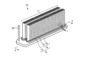
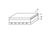
- FIG. 2A is a perspective view showing an example of the electrochemical cell device according to the first embodiment.
- Figure 2B is a cross-sectional view taken along line XX shown in Figure 2A.
- Figure 2C is a top view showing an example of the electrochemical cell device according to the first embodiment.
- the cell stack device 10 includes a cell stack 11 having a plurality of cells 1 arranged (stacked) in the thickness direction T of the cells 1 (see FIG. 1A), and a fixing member 12.
- the fixing member 12 has a fixing material 13 and a support member 14.
- the support member 14 supports the cell 1.
- the fixing material 13 fixes the cell 1 to the support member 14.
- the support member 14 also has a support 15 and a gas tank 16.
- the support member 14, which is made of a metal, has electrical conductivity.
- the support 15 has insertion holes 15a into which the lower ends of the multiple cells 1 are inserted.
- the lower ends of the multiple cells 1 and the inner wall of the insertion holes 15a are joined with a fixing material 13.
- the gas tank 16 has an opening for supplying reactive gas to the multiple cells 1 through the insertion holes 15a, and a groove 16a located around the opening.
- the outer peripheral edge of the support 15 is joined to the gas tank 16 by a bonding material 21 filled in the groove 16a of the gas tank 16.
- fuel gas is stored in an internal space 22 (see FIG. 2B) formed by the support body 15, which is the support member 14, and the gas tank 16.
- a gas circulation pipe 20 is connected to the gas tank 16.
- the fuel gas is supplied to the gas tank 16 through this gas circulation pipe 20, and is supplied from the gas tank 16 to a gas flow path 2a (see FIG. 1A) inside the cell 1.
- the fuel gas supplied to the gas tank 16 is generated in a reformer 102 (see FIG. 4), which will be described later.
- Hydrogen-rich fuel gas can be produced by steam reforming the raw fuel.
- fuel gas is produced by steam reforming, the fuel gas contains water vapor.
- the cell stack device 10 includes two rows of cell stacks 11, two supports 15, and a gas tank 16.
- Each of the two rows of cell stacks 11 includes a plurality of cells 1.
- Each cell stack 11 is fixed to each of the supports 15.
- the gas tank 16 has two through holes on its upper surface.
- a support 15 is disposed in each of the through holes.
- the internal space 22 is formed by one gas tank 16 and two supports 15.
- FIG. 2A shows a cell stack device 10 having two rows of cell stacks 11, the cell stack device may have one row of cell stacks 11 or three or more rows of cell stacks 11.
- the shape of the insertion hole 15a is, for example, an oval shape when viewed from above.
- the length of the insertion hole 15a in the arrangement direction of the cells 1, i.e., the thickness direction T, may be greater than the distance between the two end current collecting members 17 located at both ends of the cell stack 11.
- the width of the insertion hole 15a may be greater than the length of the cell 1 in the width direction W (see FIG. 1A).
- the joint between the inner wall of the insertion hole 15a and the lower end of the cell 1 is filled with a fixing material 13 and solidified. This bonds and fixes the inner wall of the insertion hole 15a to the lower end of each of the multiple cells 1, and also bonds and fixes the lower ends of the cells 1 to each other.
- the gas flow path 2a of each cell 1 communicates with the internal space 22 of the support member 14 at its lower end.
- the fixing material 13 and the bonding material 21 may be made of a material with low electrical conductivity, such as glass.
- Specific materials for the fixing material 13 and the bonding material 21 may include amorphous glass, and in particular, crystallized glass.
- any of SiO 2 -CaO based, MgO-B 2 O 3 based, La 2 O 3 -B 2 O 3 -MgO based, La 2 O 3 -B 2 O 3 -ZnO based, SiO 2 -CaO-ZnO based materials may be used, and in particular, SiO 2 -MgO based materials may be used.
- a conductive member 18 is interposed between adjacent cells 1 among the multiple cells 1.
- the conductive member 18 electrically connects the fuel electrode layer 5 of one adjacent cell 1 to the air electrode layer 8 of the other cell 1 in series. More specifically, the conductive member 18 connects the interconnector 4 electrically connected to the fuel electrode layer 5 of one adjacent cell 1 to the air electrode layer 8 of the other cell 1. Note that when the interconnector 4 is a metal or alloy, the interconnector 4 and the conductive member 18 may be integrated, or the conductive member 18 may also serve as the interconnector 4.
- an end current collecting member 17 is electrically connected to the cell 1 located on the outermost side in the arrangement direction of the multiple cells 1.
- the end current collecting member 17 is connected to a conductive part 19 that protrudes to the outside of the cell stack 11.
- the conductive part 19 collects electricity generated by power generation in the cell 1 and draws it out to the outside. Note that the end current collecting member 17 is not shown in FIG. 2A.
- the cell stack device 10 has two cell stacks 11A and 11B connected in series and functions as a single battery. Therefore, the conductive parts 19 of the cell stack device 10 are divided into a positive terminal 19A, a negative terminal 19B, and a connection terminal 19C.
- the positive terminal 19A is the positive electrode when the power generated by the cell stack 11 is output to the outside, and is electrically connected to the positive end current collector 17 of the cell stack 11A.
- the negative terminal 19B is the negative electrode when the power generated by the cell stack 11 is output to the outside, and is electrically connected to the negative end current collector 17 of the cell stack 11B.
- connection terminal 19C electrically connects the end current collecting member 17 on the negative electrode side of the cell stack 11A to the end current collecting member 17 on the positive electrode side of the cell stack 11B.
- Figure 3A is an enlarged cross-sectional view of a region R1 shown in Figure 1A.
- the solid electrolyte layer 6 includes a first element 6a.
- the first element 6a may be, for example, a lanthanide element having an electron in a 4f orbital.
- the first element 6a may be, for example, one or more elements selected from Pr, Nd, Sm, Eu, Tb, Tm, and Yb.
- the fuel electrode layer 5 includes a second element 5a.
- the second element 5a is less susceptible to change in valence than the first element 6a.
- the second element 5a may be, for example, one or more elements selected from Y, Sc, Mg, and Ca.
- valence is not likely to change means that the valence is not likely to fluctuate, that is, the valence in a solid is stable at a certain value.
- the valence of Y and Sc is stable at 3+ in a solid
- the valence of Mg and Ca is stable at 2+.
- the fuel electrode layer 5 in a reducing atmosphere is less likely to decrease in ion conductivity compared to when the fuel electrode layer 5 includes the first element 6a.
- the electrical conductivity of the fuel electrode layer 5 is less likely to decrease, and a cell 1 is obtained in which the power generation performance is less likely to decrease.
- the solid electrolyte layer 6 also includes an electrolyte material having ion conductivity.
- the solid electrolyte layer 6 may include a metal oxide containing the first element 6a as an electrolyte material.
- the first element 6a may be solid-dissolved in the electrolyte material of the solid electrolyte layer 6.
- the electrolyte material of the solid electrolyte layer 6 may include Zr or Ce.
- the electrolyte material of the solid electrolyte layer 6 may be an oxide containing Zr or Ce. Lanthanoid elements having electrons in the 4f orbit have a small ionic radius. Oxygen vacancies are likely to occur in electrolyte materials in which such elements with a small ionic radius are solid-dissolved as the first element 6a.
- Electrolyte materials in which oxygen vacancies are likely to occur tend to exhibit high ionic conductivity.
- lanthanoid elements having electrons in the 4f orbit are likely to fluctuate in valence.
- such elements are likely to fluctuate between different valence states in a solid, for example, between 2+ and 3+ valences.
- Such elements are likely to be reduced in a reducing atmosphere.
- the fuel electrode layer 5 includes an electrolyte material having ion conductivity.
- the fuel electrode layer 5 may include a metal oxide containing the second element 5a as an electrolyte material.
- the second element 5a may be solid-dissolved in the electrolyte material of the fuel electrode layer 5.
- the electrolyte material of the fuel electrode layer 5 may include Zr.
- the electrolyte material of the fuel electrode layer 5 may be an oxide containing Zr.
- the electrolyte material of the fuel electrode layer 5 may be the same as or different from the electrolyte material of the solid electrolyte layer 6.
- the second element 5a is less likely to be reduced than the first element 6a in a reducing atmosphere. Therefore, the ion conductivity of the electrolyte material in which the second element 5a is solid-dissolved is less likely to decrease even in a reducing atmosphere than the electrolyte material in which the first element 6a is solid-dissolved.
- the fuel electrode layer 5 may further include catalyst particles 5b containing a metal.
- the catalyst particles 5b may be, for example, Ni and/or NiO.
- FIG. 3B is a cross-sectional view showing another example of region R1 shown in FIG. 1A.
- the fuel electrode layer 5 may further contain a first element 6a. This improves the bonding strength between the solid electrolyte layer 6 containing the first element 6a and the fuel electrode layer 5.
- the solid electrolyte layer 6 may further contain a second element 5a. This improves the bonding strength between the fuel electrode layer 5 containing the second element 5a and the solid electrolyte layer 6.
- the solid electrolyte layer 6 may have a larger content of the first element 6a than the fuel electrode layer 5. This makes it difficult for the power generation performance to decrease even when the fuel electrode layer 5 contains the first element 6a.
- the content of the first element 6a is the total content of the plurality of first elements 6a.
- the content of the first element 6a is the molar ratio (mol%) of the first element 6a converted into oxide to the total of the elements contained in the fuel electrode layer 5 and the solid electrolyte layer 6 at a specified portion converted into oxide.
- the content of the first element 6a in each of the fuel electrode layer 5 and the solid electrolyte layer 6 can be confirmed by elemental analysis using, for example, EPMA. Specifically, a cross-sectional image including the fuel electrode layer 5 and the solid electrolyte layer 6 is taken. In the region of the taken cross-sectional image, the elements contained in the fuel electrode layer 5 and the solid electrolyte layer 6 are analyzed. From the obtained elemental analysis results, the average content (molar ratio) of the first element 6a in each portion can be calculated and compared.
- the elements contained in the fuel electrode layer 5 and the solid electrolyte layer 6 are elements detected from the electrolyte material contained in the specific portions of the fuel electrode layer 5 and the solid electrolyte layer 6. In other words, when comparing the content of the first element 6a in each portion, the content of the first element 6a in the remaining elements excluding the catalyst particles 5b contained in the fuel electrode layer 5 can be compared.
- the solid electrolyte layer 6 may contain the second element 5a in the vicinity of the surface 61 (first surface) facing the fuel electrode layer 5. This improves the bonding strength between the fuel electrode layer 5 and the solid electrolyte layer 6.
- "in the vicinity of surface 61" refers to a portion closer to surface 61 than surface 62 when surface 61 of the solid electrolyte layer 6 facing the fuel electrode layer 5 and surface 62 of the solid electrolyte layer 6 located on the opposite side to surface 61 are defined.
- the fuel electrode layer 5 may contain the first element 6a in the vicinity of the surface 51 (second surface) facing the solid electrolyte layer 6. This improves the bonding strength between the fuel electrode layer 5 and the solid electrolyte layer 6.
- “in the vicinity of surface 51” refers to a portion closer to surface 51 than surface 52 when surface 51 of the fuel electrode layer 5 facing the solid electrolyte layer 6 and surface 52 of the fuel electrode layer 5 located on the opposite side to surface 51 are defined.
- the fuel electrode layer 5 may contain the first element 6a only in the vicinity of the surface 51 (second surface) facing the solid electrolyte layer 6. Since the conductivity of the fuel electrode layer 5 is less likely to decrease, a cell 1 is obtained whose power generation performance is less likely to decrease, and the bonding strength between the fuel electrode layer 5 and the solid electrolyte layer 6 is improved.
- Fig. 4 is an external perspective view showing an example of a module according to the first embodiment.
- Fig. 4 shows a state in which the front and rear surfaces, which are part of the storage container 101, have been removed and the cell stack device 10 of the fuel cell stored inside has been removed to the rear.
- the module 100 includes a storage container 101 and a cell stack device 10 stored in the storage container 101.
- a reformer 102 is disposed above the cell stack device 10.
- the reformer 102 reforms raw fuel such as natural gas or kerosene to generate fuel gas, which is then supplied to the cell 1.
- the raw fuel is supplied to the reformer 102 through a raw fuel supply pipe 103.
- the reformer 102 may also include a vaporizer 102a that vaporizes water, and a reformer 102b.
- the reformer 102b includes a reforming catalyst (not shown) and reforms the raw fuel into fuel gas.
- Such a reformer 102 can perform steam reforming, which is a highly efficient reforming reaction.
- the fuel gas generated in the reformer 102 is then supplied to the gas flow path 2a (see Figure 1A) of the cell 1 through the gas flow pipe 20, the gas tank 16, and the support member 14.
- the temperature inside the module 100 during normal power generation is approximately 500°C to 1000°C due to the combustion of gas and power generation by the cell 1.
- such a module 100 is configured to house a cell stack device 10 that is less likely to deteriorate in power generation performance, making it possible to create a module 100 that is less likely to deteriorate in power generation performance.
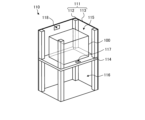
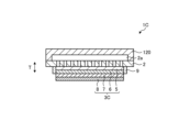
- Fig. 5 is an exploded perspective view that illustrates an example of a module housing device according to the first embodiment.
- the module housing device 110 according to this embodiment includes an outer case 111, the module 100 illustrated in Fig. 4, and auxiliary equipment (not illustrated).
- the auxiliary equipment operates the module 100.
- the module 100 and the auxiliary equipment are housed in the outer case 111. Note that some components are omitted in Fig. 5.
- the exterior case 111 of the module accommodating device 110 shown in Figure 5 has support posts 112 and an exterior plate 113.
- a partition plate 114 divides the interior of the exterior case 111 into upper and lower sections.
- the space above the partition plate 114 in the exterior case 111 is a module accommodating chamber 115 that accommodates the module 100, and the space below the partition plate 114 in the exterior case 111 is an auxiliary equipment accommodating chamber 116 that accommodates the auxiliary equipment that operates the module 100. Note that in Figure 5, the auxiliary equipment accommodated in the auxiliary equipment accommodating chamber 116 is omitted.
- the partition plate 114 also has an air flow port 117 for allowing air from the auxiliary equipment housing chamber 116 to flow toward the module housing chamber 115.
- the exterior plate 113 that constitutes the module housing chamber 115 has an exhaust port 118 for exhausting air from within the module housing chamber 115.
- a hollow flat support substrate is used, but the present invention can also be applied to a cell stack device that uses a cylindrical support substrate.
- FIG. 6A Second Embodiment Next, an electrochemical cell and an electrochemical cell device according to a second embodiment will be described with reference to FIGS. 6A to 7.
- FIG. 6A Second Embodiment
- a so-called “vertical stripe type” in which only one element part including a fuel electrode layer, a solid electrolyte layer, and an air electrode layer is provided on the surface of a support substrate is exemplified, but the present invention can also be applied to a horizontal stripe type electrochemical cell device in which so-called “horizontal stripe type” electrochemical cells are arranged in which element parts are provided at multiple locations spaced apart from each other on the surface of a support substrate and adjacent element parts are electrically connected.
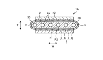
- FIG. 6A is a cross-sectional view showing an example of an electrochemical cell device according to the second embodiment.
- FIG. 6B is a cross-sectional view showing an example of an electrochemical cell included in the electrochemical cell device according to the second embodiment.
- multiple cells 1A extend in the length direction L from a pipe 22a through which fuel gas flows.
- the cells 1A have multiple element parts 3 on a support substrate 2. Inside the support substrate 2, a gas flow path 2a is provided through which the fuel gas flows from the pipe 22a.
- the cells 1A are also electrically connected to each other via a connection member 31.
- the connection member 31 is located between the element units 3 of each cell 1A, and connects adjacent cells 1A. Specifically, the connection member 31 electrically connects the air electrode layer 8 of the element unit 3 of one of the adjacent cells 1A to the fuel electrode layer 5 of the element unit 3 of the other cell 1A.
- the cell 1A includes a support substrate 2, a pair of element portions 3, and a sealing portion 30.
- the support substrate 2 is columnar, having a pair of opposing flat surfaces, a first surface n1 and a second surface n2, and a pair of arc-shaped side surfaces m connecting the first surface n1 and the second surface n2.
- the pair of element portions 3 are positioned so as to face each other on the first surface n1 and the second surface n2 of the support substrate 2.
- the sealing portion 30 is positioned so as to cover the side surface m of the support substrate 2.
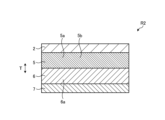
- FIG. 7 is an enlarged cross-sectional view of region R2 shown in FIG. 6B.
- the solid electrolyte layer 6 includes a first element 6a.
- the fuel electrode layer 5 includes a second element 5a whose valence is less likely to fluctuate than the first element 6a.
- the fuel electrode layer 5 may further include catalyst particles 5b containing a metal.
- the fuel electrode layer 5 in a reducing atmosphere is less likely to have a decreased ionic conductivity than when the fuel electrode layer 5 includes the first element 6a.
- the electrical conductivity of the fuel electrode layer 5 is less likely to decrease, resulting in a cell 1A whose power generation performance is less likely to decrease.
- Fig. 8 is a perspective view showing an example of an electrochemical cell according to the third embodiment
- Fig. 9 is a partial cross-sectional view of the electrochemical cell shown in Fig. 8.
- cell 1B has an element portion 3B in which a fuel electrode layer 5, a solid electrolyte layer 6, an intermediate layer 7, and an air electrode layer 8 are stacked. In element portion 3B, the solid electrolyte layer 6 is sandwiched between the fuel electrode layer 5 and the air electrode layer 8.
- multiple cells 1B are electrically connected by conductive members 91, 92, which are adjacent metal layers. The conductive members 91, 92 electrically connect adjacent cells 1B to each other, and have a gas flow path that supplies gas to the fuel electrode layer 5 or the air electrode layer 8.
- cell 1B has a sealing material that hermetically seals the fuel gas flow path and the oxygen-containing gas flow path of the flat cell stack.
- the sealing material is a fixing member 96 for cell 1B, and has a bonding material 93 and support members 94 and 95 that are frames.
- the bonding material 93 may be glass or a metal material such as silver solder.
- the support member 94 may be a so-called separator that separates the fuel gas flow path from the oxygen-containing gas flow path.
- the material of the support members 94, 95 may be, for example, a conductive metal or an insulating ceramic. Either or both of the support members 94, 95 may be made of an insulating material. If the support member 94 is made of metal, the support member 94 may be integrated with the conductive member 92. If the support member 95 is made of metal, the support member 95 may be integrated with the conductive member 91.
- One of the support members 94, 95 is insulating, electrically insulating the two conductive members 91, 92 that sandwich the flat cell from each other.
- FIG. 10 is an enlarged cross-sectional view of region R3 shown in FIG. 9.
- the solid electrolyte layer 6 contains a first element 6a.
- the fuel electrode layer 5 contains a second element 5a whose valence is less likely to fluctuate than the first element 6a.
- the fuel electrode layer 5 may further contain catalyst particles 5b containing a metal.
- the fuel electrode layer 5 in a reducing atmosphere is less likely to have a decreased ionic conductivity than when the fuel electrode layer 5 includes the first element 6a.
- the electrical conductivity of the fuel electrode layer 5 is less likely to decrease, resulting in a cell 1B in which the power generation performance is less likely to decrease.
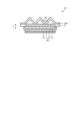
- Fig. 11A is a cross-sectional view showing an example of an electrochemical cell according to the fourth embodiment.
- Fig. 11B and Fig. 11C are cross-sectional views showing another example of an electrochemical cell according to the fourth embodiment.
- Fig. 12 is an enlarged view of a region R4 shown in Fig. 11A.
- Fig. 12 can also be applied to the examples of Fig. 11B and Fig. 11C.
- the cell 1C has an element section 3C in which a fuel electrode layer 5, a solid electrolyte layer 6, an intermediate layer 7, and an air electrode layer 8 are laminated, and a support substrate 2.
- the support substrate 2 has a through hole or a fine hole at a portion in contact with the element section 3C, and has a member 120 located outside the gas flow path 2a.
- the support substrate 2 can circulate gas between the gas flow path 2a and the element section 3C.
- the support substrate 2 may be composed of, for example, one or more metal plates.
- the material of the metal plate may contain chromium.
- the metal plate may have a conductive coating layer.
- the support substrate 2 electrically connects adjacent cells 1C to each other.
- the element section 3C may be formed directly on the support substrate 2, or may be bonded to the support substrate 2 by a bonding material.
- the side of the fuel electrode layer 5 is covered with a solid electrolyte layer 6, which airtightly seals the gas flow path 2a through which the fuel gas flows.
- the side of the fuel electrode layer 5 may be covered and sealed with a sealant 9 made of dense glass or ceramic.
- the sealant 9 that covers the side of the fuel electrode layer 5 may have electrical insulation properties.
- gas flow path 2a of the support substrate 2 may be formed by a member 120 having projections and recesses as shown in FIG. 11C.
- FIG. 12 is an enlarged cross-sectional view of region R4 shown in FIG. 11A.
- the solid electrolyte layer 6 includes a first element 6a.
- the fuel electrode layer 5 includes a second element 5a whose valence is less likely to fluctuate than the first element 6a.
- the fuel electrode layer 5 may further include catalyst particles 5b containing a metal.
- the fuel electrode layer 5 in a reducing atmosphere is less likely to have a decreased ionic conductivity than when the fuel electrode layer 5 includes the first element 6a.
- the electrical conductivity of the fuel electrode layer 5 is less likely to decrease, resulting in a cell 1C whose power generation performance is less likely to decrease.
- a fuel cell, a fuel cell stack device, a fuel cell module, and a fuel cell device are shown as examples of an “electrochemical cell,” “electrochemical cell device,” “module,” and “module housing device,” but other examples may be an electrolysis cell, an electrolysis cell stack device, an electrolysis module, and an electrolysis device, respectively.
- the electrolysis cell has a first electrode layer and a second electrode layer, and decomposes water vapor into hydrogen and oxygen, or carbon dioxide into carbon monoxide and oxygen, when supplied with power.
- an oxide ion conductor or a hydrogen ion conductor is shown as an example of an electrolyte material for an electrochemical cell, but a hydroxide ion conductor may also be used.
- Such an electrolysis cell, an electrolysis cell stack device, an electrolysis module, and an electrolysis device can improve electrolysis performance.
- an electrochemical cell includes a first electrode layer; A second electrode layer; a solid electrolyte layer located between the first electrode layer and the second electrode layer, the solid electrolyte layer contains a first element,
- the first electrode layer includes a second element whose valence is less likely to fluctuate than that of the first element.
- the first electrode layer contains the first element
- the solid electrolyte layer may have a larger content of the first element than the first electrode layer.
- the first electrode layer may further include catalyst particles containing a metal.
- the first electrode layer and the solid electrolyte layer contain an electrolyte material having ion conductivity; The first element and the second element may be dissolved in the electrolyte material.
- the electrolyte material may contain Zr or Ce.
- the first element may be one or more elements selected from Pr, Nd, Sm, Eu, Tb, Tm, and Yb.
- the second element may be one or more elements selected from Y, Sc, Mg, and Ca.
- the solid electrolyte layer may contain the second element in the vicinity of a first surface facing the first electrode layer.
- the first electrode layer may contain the first element in the vicinity of a second surface facing the solid electrolyte layer.
- the first electrode layer may contain the first element only in the vicinity of the second surface.
- the electrochemical cell device has a cell stack including any one of the electrochemical cells (1) to (10) above.
- the module (12) comprises the electrochemical cell device (11) described above, and a container for housing the electrochemical cell device.
- the module housing device (13) includes the module (12) and Auxiliary equipment for operating the module; and an exterior case that houses the module and the auxiliary equipment.
Landscapes
- Chemical & Material Sciences (AREA)
- Engineering & Computer Science (AREA)
- Electrochemistry (AREA)
- Chemical Kinetics & Catalysis (AREA)
- Materials Engineering (AREA)
- General Chemical & Material Sciences (AREA)
- Metallurgy (AREA)
- Organic Chemistry (AREA)
- Manufacturing & Machinery (AREA)
- Sustainable Energy (AREA)
- Sustainable Development (AREA)
- Life Sciences & Earth Sciences (AREA)
- Inorganic Chemistry (AREA)
- Ceramic Engineering (AREA)
- Fuel Cell (AREA)
Priority Applications (1)
| Application Number | Priority Date | Filing Date | Title |
|---|---|---|---|
| JP2025524100A JPWO2024247989A1 (https=) | 2023-05-31 | 2024-05-28 |
Applications Claiming Priority (2)
| Application Number | Priority Date | Filing Date | Title |
|---|---|---|---|
| JP2023090266 | 2023-05-31 | ||
| JP2023-090266 | 2023-05-31 |
Publications (1)
| Publication Number | Publication Date |
|---|---|
| WO2024247989A1 true WO2024247989A1 (ja) | 2024-12-05 |
Family
ID=93658006
Family Applications (1)
| Application Number | Title | Priority Date | Filing Date |
|---|---|---|---|
| PCT/JP2024/019504 Ceased WO2024247989A1 (ja) | 2023-05-31 | 2024-05-28 | 電気化学セル、電気化学セル装置、モジュールおよびモジュール収容装置 |
Country Status (2)
| Country | Link |
|---|---|
| JP (1) | JPWO2024247989A1 (https=) |
| WO (1) | WO2024247989A1 (https=) |
Citations (3)
| Publication number | Priority date | Publication date | Assignee | Title |
|---|---|---|---|---|
| JP2001118590A (ja) * | 1999-10-21 | 2001-04-27 | Toto Ltd | 高導電性固体電解質膜及びその製造方法 |
| KR20100024545A (ko) * | 2008-08-26 | 2010-03-08 | 한국에너지기술연구원 | 입방정 이터비아 안정화 지르코니아 및 이를 이용한 고체산화물연료전지 |
| JP2015170602A (ja) * | 2014-03-06 | 2015-09-28 | 株式会社ケーセラセル | 固体酸化物燃料電池用高イオン伝導性ジルコニア電解質、高イオン伝導性ジルコニア電解質焼結体、固体酸化物燃料電池用単電池、及び、固体酸化物燃料電池用高イオン伝導性ジルコニア電解質の合成方法 |
-
2024
- 2024-05-28 WO PCT/JP2024/019504 patent/WO2024247989A1/ja not_active Ceased
- 2024-05-28 JP JP2025524100A patent/JPWO2024247989A1/ja active Pending
Patent Citations (3)
| Publication number | Priority date | Publication date | Assignee | Title |
|---|---|---|---|---|
| JP2001118590A (ja) * | 1999-10-21 | 2001-04-27 | Toto Ltd | 高導電性固体電解質膜及びその製造方法 |
| KR20100024545A (ko) * | 2008-08-26 | 2010-03-08 | 한국에너지기술연구원 | 입방정 이터비아 안정화 지르코니아 및 이를 이용한 고체산화물연료전지 |
| JP2015170602A (ja) * | 2014-03-06 | 2015-09-28 | 株式会社ケーセラセル | 固体酸化物燃料電池用高イオン伝導性ジルコニア電解質、高イオン伝導性ジルコニア電解質焼結体、固体酸化物燃料電池用単電池、及び、固体酸化物燃料電池用高イオン伝導性ジルコニア電解質の合成方法 |
Also Published As
| Publication number | Publication date |
|---|---|
| JPWO2024247989A1 (https=) | 2024-12-05 |
Similar Documents
| Publication | Publication Date | Title |
|---|---|---|
| EP4394958A1 (en) | Electrochemical cell, electrochemical cell device, module, and module storage device | |
| JP7672999B2 (ja) | 電気化学セル、電気化学セル装置、モジュールおよびモジュール収容装置 | |
| JP7692059B2 (ja) | 電気化学セル装置、モジュールおよびモジュール収容装置 | |
| JP7583227B2 (ja) | 電気化学セル、電気化学セル装置、モジュールおよびモジュール収容装置 | |
| JP7736801B2 (ja) | 電気化学セル、電気化学セル装置、モジュールおよびモジュール収容装置 | |
| JP7657386B1 (ja) | 固体電解質層、電気化学セル、電気化学セル装置、モジュールおよびモジュール収容装置 | |
| WO2024247989A1 (ja) | 電気化学セル、電気化学セル装置、モジュールおよびモジュール収容装置 | |
| JP7794994B2 (ja) | 電気化学セル、電気化学セル装置、モジュールおよびモジュール収容装置 | |
| JP7525759B1 (ja) | 固体電解質層、電気化学セル、電気化学セル装置、モジュールおよびモジュール収容装置 | |
| WO2024150829A1 (ja) | 電気化学セル、電気化学セル装置、モジュールおよびモジュール収容装置 | |
| EP4489151A1 (en) | Electrochemical cell, electrochemical cell device, module, and module accommodating device | |
| JP7678720B2 (ja) | セル、セルスタック装置、モジュールおよびモジュール収容装置 | |
| WO2024143355A1 (ja) | 電気化学セル、電気化学セル装置、モジュールおよびモジュール収容装置 | |
| WO2025094956A1 (ja) | 電気化学セル、電気化学セル装置、モジュールおよびモジュール収容装置 | |
| JP2024048859A (ja) | 電気化学セル装置、モジュールおよびモジュール収容装置 | |
| WO2024117052A1 (ja) | 複合部材、電気化学セル、電気化学セル装置、モジュールおよびモジュール収容装置 | |
| JP2025153056A (ja) | 電気化学セル、電気化学セル装置、モジュールおよびモジュール収容装置 | |
| WO2026029158A1 (ja) | 電気化学セル、電気化学セル装置、モジュールおよびモジュール収容装置 | |
| WO2026048889A1 (ja) | 電気化学セル、電気化学セル装置、モジュールおよびモジュール収容装置 | |
| WO2025070717A1 (ja) | 電気化学セル、電気化学セル装置、モジュールおよびモジュール収容装置 | |
| WO2025047876A1 (ja) | 電気化学セル、電気化学セル装置、モジュールおよびモジュール収容装置 | |
| JP2025021234A (ja) | 電気化学セル、電気化学セル装置、モジュールおよびモジュール収容装置 | |
| JP2026008859A (ja) | 電気化学セル、電気化学セル装置、モジュールおよびモジュール収容装置 | |
| WO2024248059A1 (ja) | 導電部材、電気化学セル装置、モジュールおよびモジュール収容装置 | |
| WO2024162413A1 (ja) | 固体電解質層、電気化学セル、電気化学セル装置、モジュールおよびモジュール収容装置 |
Legal Events
| Date | Code | Title | Description |
|---|---|---|---|
| 121 | Ep: the epo has been informed by wipo that ep was designated in this application |
Ref document number: 24815472 Country of ref document: EP Kind code of ref document: A1 |
|
| ENP | Entry into the national phase |
Ref document number: 2025524100 Country of ref document: JP Kind code of ref document: A |
|
| NENP | Non-entry into the national phase |
Ref country code: DE |