WO2024247136A1 - 制御装置、ロボットシステム及びロボットの制御方法 - Google Patents
制御装置、ロボットシステム及びロボットの制御方法 Download PDFInfo
- Publication number
- WO2024247136A1 WO2024247136A1 PCT/JP2023/020185 JP2023020185W WO2024247136A1 WO 2024247136 A1 WO2024247136 A1 WO 2024247136A1 JP 2023020185 W JP2023020185 W JP 2023020185W WO 2024247136 A1 WO2024247136 A1 WO 2024247136A1
- Authority
- WO
- WIPO (PCT)
- Prior art keywords
- target
- work
- candidates
- control device
- evaluation value
- Prior art date
- Legal status (The legal status is an assumption and is not a legal conclusion. Google has not performed a legal analysis and makes no representation as to the accuracy of the status listed.)
- Ceased
Links
Images







Classifications
-
- B—PERFORMING OPERATIONS; TRANSPORTING
- B25—HAND TOOLS; PORTABLE POWER-DRIVEN TOOLS; MANIPULATORS
- B25J—MANIPULATORS; CHAMBERS PROVIDED WITH MANIPULATION DEVICES
- B25J13/00—Controls for manipulators
Definitions
- the technology disclosed herein relates to a control device, a robot system, and a method for controlling a robot.
- Control devices that control robots that place workpieces are known in the past. For example, the control device described in Patent Document 1 calculates the placement position of the workpiece. The control device scans the free space in the storage container to search for a placement position where the workpiece will not interfere with other existing workpieces.
- the control device of the present disclosure includes a searcher that searches for multiple position candidates that are candidates for the target placement position of the target work in the storage space, an evaluator that calculates an evaluation value for each of the multiple position candidates, and a determiner that determines the target placement position from among the multiple position candidates based on the evaluation value, and the evaluator calculates the evaluation value based on the vacant space in the storage space after the target work is placed in each of the position candidates.
- the robot system disclosed herein comprises a robot having a robot arm and a hand attached to the robot arm, and the control device.
- the robot control method disclosed herein is a method for controlling a robot having a robot arm and a hand attached to the robot arm, and includes searching for a plurality of position candidates that are candidates for a target position for placing a target workpiece in an accommodation space, calculating an evaluation value for each of the plurality of position candidates, and determining the target position for placing from among the plurality of position candidates based on the evaluation value, and calculating the evaluation value calculates the evaluation value based on the vacant space in the accommodation space after the target workpiece has been placed in each of the position candidates.
- the control device can achieve appropriate placement of multiple workpieces.
- the robot system described above can achieve appropriate placement of multiple workpieces.
- the robot control method described above makes it possible to realize appropriate placement of multiple workpieces.
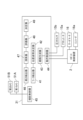
- FIG. 1 is a schematic diagram showing the configuration of a robot system.
- FIG. 2 is a diagram showing a schematic hardware configuration of the robot control device and the main control device.
- FIG. 3 is a block diagram showing the configuration of a control system of the processor.
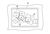
- FIG. 4 is a view of the inside of the first container as seen from above.
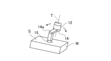
- FIG. 5 is an explanatory diagram showing the hand when picking up the target workpiece.
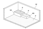
- FIG. 6 is an exemplary perspective view showing the inside of the second container.
- FIG. 7 is a schematic plan view of the inside of the second container for explaining the search for position candidates.
- FIG. 8 is a schematic plan view of the inside of the second container for explaining the narrowing down of position candidates.
- FIG. 1 is a schematic diagram showing the configuration of a robot system.
- FIG. 2 is a diagram showing a schematic hardware configuration of the robot control device and the main control device.
- FIG. 3 is a block diagram showing the configuration of a control system of the processor.
- FIG. 4 is
- FIG. 9 is an exemplary perspective view of the inside of the second container showing the empty space after the target workpiece has been placed.
- FIG. 10 is a diagram showing a plurality of types of virtual workpieces.
- FIG. 11 is a schematic plan view of the inside of the second container for explaining the calculation of the evaluation value.
- FIG. 12 is a flow chart of the pick and place process.
- FIG. 13 is a flow chart of the pickup position planning subroutine.
- FIG. 14 is a schematic diagram showing the relative position and orientation of the hand when viewed in the direction of the reference axis.
- FIG. 10 is a diagram showing a plurality of types of virtual workpieces.
- FIG. 11 is a schematic plan view of the inside of the second container for explaining the calculation of the evaluation value.
- FIG. 12 is a flow chart of the pick and place process.
- FIG. 13 is a flow chart of the pickup position planning subroutine.
- FIG. 14 is a schematic diagram showing the relative position and orientation of the hand when viewed in
- FIG. 15 is a schematic diagram showing a region where the angle between the side serving as the reference side and the offset direction of the suction unit is equal to or greater than a threshold value ⁇ , and a region where the angle is less than the threshold value ⁇ .
- FIG. 16 is a flow chart of the place location planning subroutine.
- Figure 1 is a schematic diagram showing the configuration of a robot system 100.
- the robot system 100 includes a robot 1 and a main control device 3 that controls the robot 1.
- the main control device 3 controls the robot 1 to cause the robot 1 to execute a process.
- the process performed by the robot 1 is a pick-and-place process.
- the robot 1 picks up a target workpiece from a first container 91 in which multiple workpieces are piled up randomly, and transfers it into a second container 92.
- the robot 1 arranges the target workpieces in a regular pattern in the second container 92.
- the robot system 100 arranges the multiple workpieces in the first container 91 into the second container 92 by repeating the pick-and-place process.
- the target workpiece has, for example, a roughly rectangular parallelepiped shape.
- the robot system 100 may include a camera 51 that captures an image of the workpiece.
- the camera 51 may include a first camera 51A that captures an image inside the first container 91 and a second camera 51B that captures an image inside the second container 92.
- the first camera 51A is fixedly disposed above the first container 91.
- the first camera 51A captures an image inside the first container 91 from above.
- the first camera 51A captures an image including a plurality of workpieces inside the first container 91.
- the second camera 51B is fixedly disposed above the second container 92.
- the second camera 51B captures an image inside the second container 92 from above.
- the second camera 51B captures an image including a plurality of workpieces inside the second container 92.
- the first camera 51A and the second camera 51B are not distinguished from each other, they will be simply referred to as cameras 51.
- the image is a two-dimensional image or a three-dimensional image.
- the three-dimensional image can be point cloud data, an RGB-D image, an RGB image, a depth image, or a voxel, etc.
- the camera 51 can be a three-dimensional camera, i.e., an RGB-D camera that outputs an RGB-D image, a stereo camera that acquires an RGB image, or a three-dimensional vision sensor that acquires point cloud data, etc.
- the robot 1 has a robot arm 12 and a hand 14 attached to the robot arm 12.
- the robot 1 is an industrial robot.
- the hand 14 is a so-called end effector.
- a base coordinate system of three orthogonal axes is defined in a space in which the robot 1 is disposed.
- the robot arm 12 is configured to operate in a three-dimensional manner. Specifically, the robot arm 12 is configured to perform operations including translation with at least three degrees of freedom.
- the robot arm 12 is a vertical multi-joint robot arm.
- the robot arm 12 is supported by the base 10.
- the robot arm 12 has multiple links, multiple joints that connect the multiple links, and a servo motor that rotates the multiple joints.
- the robot arm 12 has a first link 12a connected to the base 10, a second link 12b connected to the first link 12a, a third link 12c connected to the second link 12b, a fourth link 12d connected to the third link 12c, and a fifth link 12e connected to the fourth link 12d.
- the base 10 and the first link 12a are connected to each other via a first joint 13a that can rotate around an axis extending in the vertical direction.
- the first link 12a and the second link 12b are connected to each other via a second joint 13b that can rotate around an axis extending in the horizontal direction.
- the second link 12b and the third link 12c are connected to each other via a third joint 13c that can rotate around an axis extending in the horizontal direction.
- the third link 12c and the fourth link 12d are connected to each other via a fourth joint 13d that can rotate around the axis of the fourth link 12d (i.e., the direction in which the fourth link 12d extends).
- the fourth link 12d and the fifth link 12e are connected to each other via a fifth joint 13e that can rotate around an axis perpendicular to the axis of the fourth link 12d.
- the robot arm 12 has servo motors 16 (see Figure 2) that rotate each joint.
- Each servo motor 16 has an encoder 16a (see Figure 2).
- the robot arm 12 thus configured is configured to perform translational movements in the directions of each of the three orthogonal axes, and rotational movements around each of the three orthogonal axes.
- the hand 14 includes a suction device 15 that is positioned at a position offset in the radial direction around a predetermined reference axis T of the robot arm 12.
- the suction device 15 is positioned eccentrically with respect to the reference axis T.
- the hand 14 has a base 14a that is attached to the robot arm 12.
- the base 14a extends in the radial direction around the reference axis T.
- the suction device 15 is attached to the end of the base 14a that is farther from the reference axis T via a plate, block, or the like.
- the suction device 15 is configured to be able to change its position relative to the robot arm 12.
- the hand 14 is attached to the robot arm 12 so as to be rotatable around the reference axis T.
- the hand 14 is connected to the tip of the robot arm 12, i.e., the fifth link 12e.
- the fifth link 12e and the hand 14 are connected to each other via the sixth joint 13f so as to be rotatable around the reference axis T.
- the suction device 15 changes its relative position with respect to the robot arm 12 by rotating the hand 14 around the reference axis T.
- the hand 14 sucks the workpiece with a suction device 15.
- the suction device 15 has a suction pad.
- An air hose that is connected to a negative pressure generator is connected to the suction device 15.
- the air hose is provided with a solenoid valve that serves as an actuator 15a (see Figure 2). By controlling the solenoid valve, the suction device 15 can switch between suction and release.
- the suction device 15 sucks the surface of the target workpiece W.
- the air hose is provided with a pressure sensor 15b (see Figure 2).
- the pressure sensor 15b detects the magnitude of the negative pressure in the air hose.
- FIG. 2 is a diagram showing the general hardware configuration of the robot controller 2 and the main controller 3.
- the main controller 3 transmits and receives signals and information to and from the robot controller 2.
- the main controller 3 controls the robot 1 via the robot controller 2.
- the main controller 3 outputs commands to the robot controller 2.
- the robot controller 2 controls the servo motor 16 of the robot arm 12 in response to commands from the main controller 3.
- Images from the first camera 51A and the second camera 51B are input to the main control device 3.
- the main control device 3 detects the target workpiece W based on the images.
- the main control device 3 generates a target path for the robot 1 based on the detected target workpiece W, and outputs a command corresponding to the generated target path to the robot control device 2.
- An actuator 15a and a pressure sensor 15b are connected to the main control device 3.
- the main control device 3 controls suction by the hand 14 via the actuator 15a and the pressure sensor 15b.
- the main control device 3 is an example of a control device.
- the robot control device 2 has a processor 21, a memory 22, and a memory 23.
- the processor 21 controls the entire robot control device 2.
- the processor 21 performs various types of arithmetic processing.
- the processor 21 is formed of a processor such as a CPU (Central Processing Unit).
- the processor 21 may also be formed of an MCU (Micro Controller Unit), an MPU (Micro Processor Unit), an FPGA (Field Programmable Gate Array), a PLC (Programmable Logic Controller), a system LSI, etc.
- the memory 22 stores the programs executed by the processor 21 and various data.
- the memory 22 is formed of a non-volatile memory, a hard disc drive (HDD), a solid state drive (SSD), etc.
- the memory 23 temporarily stores data, etc.
- the memory 23 is formed of a volatile memory.
- the processor 21 drives the servo motor 16 based on a command from the main control device 3. At this time, the robot control device 2 feedback controls the current supplied to the servo motor 16 based on the detection result of the encoder 16a.
- the main control device 3 has a processor 31, a memory 32, and a memory 33.
- the processor 31 controls the entire main control device 3.
- the processor 31 performs various types of arithmetic processing.
- the processor 31 is formed of a processor such as a CPU (Central Processing Unit).
- the processor 31 may also be formed of an MCU (Micro Controller Unit), an MPU (Micro Processor Unit), an FPGA (Field Programmable Gate Array), a PLC (Programmable Logic Controller), a system LSI, etc.
- the memory 32 stores the programs and various data executed by the processor 31.
- the memory 32 is formed of a non-volatile memory, a HDD (Hard Disc Drive), an SSD (Solid State Drive), etc.
- the memory 32 stores an object detection program that detects objects, a position and orientation determination program that determines the position and orientation of the hand 14, and a path generation program that generates a target path for the robot 1.
- the various programs cause the main control device 3 to realize various functions.
- Memory 33 temporarily stores data, etc.
- memory 33 is formed of a volatile memory.
- Memory 33 stores images from camera 51.
- the processor 31 causes the robot 1 to execute a picking operation in which the hand 14 moves to the target workpiece W and causes the suction device 15 to pick up the target workpiece W, and a placing operation in which the hand 14 that has picked up the target workpiece W moves to a target placement position and causes the suction device 15 to release the suction from the target workpiece W.
- the processor 31 causes the robot 1 to execute a placing operation after the picking operation.
- the processor 31 determines the relative position and orientation of the hand 14, which is the position and orientation of the hand 14 with respect to the target workpiece W at the time of picking. Prior to the placing operation, the processor 31 determines the target placement position of the target workpiece W at the time of placing.
- FIG. 3 is a block diagram showing the configuration of the control system of the processor 31.
- the processor 31 realizes various functions by reading out a program from the storage device 32 to the memory 33 and expanding it.
- the processor 31 functions as a searcher 47 that searches for multiple position candidates that are candidates for the target position of the target work in the storage space, an evaluator 48 that calculates the evaluation value of each of the multiple position candidates, and a determiner 49 that determines the target position of the target work based on the evaluation value from among the multiple position candidates.
- the processor 31 also functions as a height detector 46 that detects height information of the storage space.
- the processor 31 can also function as a work detector 41 that detects the target work W to be picked, a position and orientation determiner 42 that determines the relative position and orientation of the hand 14, a path generator 43 that generates the target path of the robot arm 12 and the hand 14, an operation controller 44 that causes the robot arm 12 and the hand 14 to execute the picking operation and the placing operation, and an image capture controller 45 that causes the camera 51 to acquire an image.
- the photography controller 45 controls the first camera 51A and the second camera 51B to capture images from each of the first camera 51A and the second camera 51B.
- the first camera 51A captures an image of the inside of the first container 91.
- the second camera 51B captures an image of the inside of the second container 92.
- the photography controller 45 stores the images from the cameras 51 in the memory 33.
- the work detector 41 detects the target work W from within the image by image recognition.
- the image may include multiple workpieces.
- the work detector 41 performs plane detection, for example, by RANSAC (Random Sample Consensus) to detect the surface of the target work W (hereinafter referred to as the "target surface S").
- RANSAC Random Sample Consensus
- the work detector 41 detects the target work W by detecting a plane of a predetermined shape included in the image.
- FIG. 4 is a view of the inside of the first container 91 from above.
- the work detector 41 can detect multiple target surfaces S, i.e., multiple target workpieces W.
- the work detector 41 determines at least the center position of the target surface S, the normal direction of the target surface S, the vertical and horizontal orientations of the target surface S, and the size of the target surface S (e.g., the vertical and horizontal sizes).
- the size of the target surface S may be stored in advance in the memory 32.
- the position and orientation determiner 42 determines the relative position and orientation of the hand 14 during picking, using the target surface S detected as the target workpiece W as the suction surface.
- FIG. 5 is an explanatory diagram showing the hand 14 when suctioning the target workpiece W.
- the position and orientation of the hand 14 is determined so that the suction device 15 is located at the suction position on the target surface S.
- the suction position is, for example, the center of the target surface S. Since the suction device 15 is eccentric with respect to the reference axis T, even if the position of the suction device 15 is determined, the reference axis T can be positioned at any position within 360 degrees around the suction device 15.
- the relative position and orientation of the hand 14 is determined by the position of the suction device 15 relative to the target workpiece W, the position of the reference axis T, and the orientation of the reference axis T. In other words, when the relative position and orientation of the hand 14 is determined, the position and orientation of the reference axis T relative to the target workpiece W and the offset direction of the suction device 15 relative to the reference axis T are determined.
- the "offset direction of the suction device 15 relative to the reference axis T" is the direction in which a straight line connecting the reference axis T and the suction device 15 extends from the reference axis T when viewed in the direction of the reference axis T, and in this example, is the direction in which the base 14a extends from the reference axis T.
- the offset direction of the suction device 15 relative to the reference axis T is the eccentric direction of the suction device 15 relative to the reference axis T.
- the offset direction of the suction device 15 relative to the reference axis T will be simply referred to as the "offset direction of the suction device 15."
- the position and orientation determiner 42 determines the relative position and orientation of the hand 14 so that when viewed in the direction of the reference axis T, the reference side of the target workpiece W (hereinafter referred to as the "reference side") does not overlap with the hand 14, and the offset direction of the suction device 15 relative to the reference axis T is non-parallel to the reference side.
- the "side of the target workpiece W" is the part of the target workpiece W that faces to the side. Specifically, it is the part of the target workpiece W that faces in a direction that intersects with the normal direction when the target workpiece W is viewed in the direction of the reference axis T. In other words, the side of the target workpiece W is the side of the target workpiece W that intersects with the suction surface that is suctioned by the suction device 15.
- the target workpiece W since the target workpiece W has a roughly rectangular parallelepiped shape, the part of the target workpiece W that faces in a direction that is roughly perpendicular to the normal direction of the target surface S, that is, the four side surfaces other than the target surface S and the surface opposite it, are the side of the target workpiece W.
- the path generator 43 generates a target path for the robot arm 12 and the hand 14.
- the target path is an ordered set of target positions and target postures of the robot arm 12 and the hand 14. That is, the target path is a change over time of the target position and target posture of the robot arm 12 and the hand 14.
- the target path may be an ordered set of target rotation angles of each joint of the robot arm 12 (including the sixth joint 13f) that realizes the change over time of the target position and target posture of the robot arm 12 and the hand 14.
- the target path uniquely defines the position and posture of the robot arm 12 and the hand 14.
- the target path also defines the target rotation position of the suction device 15 around the reference axis T.
- the path generator 43 generates a target path for the robot arm 12 and the hand 14 to move the hand 14 to the determined relative position and posture of the hand 14.
- the path generator 43 generates a target path for the robot arm 12 and the hand 14 to move the target workpiece W to the determined place target position.
- the path generator 43 executes path planning using the Probabilistic Roadmap Method (PRM) or the Rapidly-Exploring Random Tree (RRT), etc. In these methods, the path generator 43 also executes an interference check, i.e., checks whether the robot arm 12 and the hand 14 interfere with other objects.
- PRM Probabilistic Roadmap Method
- RRT Rapidly-Exploring Random Tree
- an interference check i.e., checks whether the robot arm 12 and the hand 14 interfere with other objects.
- an interference check for example, an interference check using point cloud data or CAD data is performed.
- the motion controller 44 outputs commands according to the target path to the robot control device 2. Specifically, the motion controller 44 outputs commands according to the target rotation angles of each joint of the robot arm 12 to the robot control device 2. As described above, the robot control device 2 drives the servo motors 16 based on the commands, causing the robot arm 12 and hand 14 to move along the target path.
- the operation controller 44 switches between suction by the suction device 15 and release of the suction by controlling the actuator 15a of the hand 14.
- the operation controller 44 controls the actuator 15a to generate negative pressure in the suction device 15, thereby causing the suction device 15 to suction the workpiece.
- the operation controller 44 controls the actuator 15a to release the negative pressure in the suction device 15, thereby causing the suction device 15 to release the suction of the workpiece.
- the operation controller 44 determines whether suction of the target workpiece W by the suction device 15 has been completed based on the detection result of the pressure sensor 15b.
- the operation controller 44 determines whether suction has been completed when the negative pressure detected by the pressure sensor 15b is equal to or greater than a predetermined threshold value.
- the height detector 46 detects height information of the storage space in which the target workpiece W is to be stored.
- the storage space is inside the second container 92.
- the height information is information about the height of each position in the storage space, specifically, the height information of each position inside the second container 92. In areas inside the second container 92 where the bottom surface is exposed, the height information is the height of each position on the bottom surface. In areas inside the second container 92 where the workpiece is present, the height information is the height of each position on the top surface of the workpiece.
- the height detector 46 detects the height information of the storage space based on an image inside the second container 92.
- the height detector 46 obtains the height information of the storage space, for example, by performing preprocessing such as discretization or smoothing from the point cloud data of the three-dimensional image.
- the height detector 46 outputs the height information of the storage space as a height map.
- the searcher 47 searches for multiple position candidates that are candidates for the target placement position of the target work W in the storage space.
- the work detector 41 and the position and orientation determiner 42 identify the target work W, and the dimensions of the target work W are also obtained.
- the searcher 47 searches for positions in the storage space where the target work W can be placed, as candidate placement target positions.
- the searcher 47 detects a space in the storage space where the target work W can be placed (hereinafter referred to as a "placeable space”).
- the searcher 47 detects a plane P in the storage space where the target work W can be placed (hereinafter referred to as a "placeable surface”) based on the height map, and the space above the placeable surface P is the placeable space.
- Figure 6 is an exemplary perspective view showing the inside of the second container 92.
- the surface with dots is the placeable surface P.
- the placeable surface P is a plane exposed upward and is an area of uniform height in the height map.
- the placeable surface P is an exposed part of the bottom surface of the second container 92.
- top surface of the existing work W0 is also exposed, it can become the placeable surface P. Note that if multiple existing works W0 are lined up, the top surfaces of the existing works W0 are exposed upward, and the heights of the top surfaces of the existing works W0 are uniform, the top surfaces of the existing works W0 become a single placeable surface P. In the example of Figure 6, the top surfaces of the two existing workpieces W0 are each treated as separate placeable surfaces P.
- the searcher 47 determines whether the target work W can be placed at each position while changing the position of the target work W on the possible placement surface P.
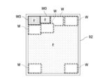
- FIG. 7 is a schematic plan view of the inside of the second container 92 to explain the search for possible positions. A position determined to be possible for placement becomes a possible position. Whether or not the target work W can be placed is determined based on whether or not the target work W can be placed without interfering with other objects.
- the searcher 47 sets the size of the target work W for search (see dashed line) to the actual size of the target work W (see dashed line) plus a predetermined margin. Specifically, the searcher 47 enlarges the bottom surface of the target work W by the amount of the predetermined margin.
- the searcher 47 searches for position candidates not only on the bottom surface of the second container 92, but also on the top surface of the existing workpiece W0 as a possible placement surface P.
- the searcher 47 narrows down the multiple position candidates from the viewpoint of work storage efficiency. For example, the searcher 47 selects a position candidate corresponding to a corner space in the storage space from the multiple position candidates.
- FIG. 8 is a schematic plan view of the inside of the second container 92 to explain the narrowing down of the position candidates. Inside the second container 92, a corner may be formed by the side wall of the second container 92 and the side surface of the existing work W0. When storing the work in the second container 92, it is preferable from the viewpoint of work storage efficiency to pack the work into a space including the corner. Therefore, as shown in FIG. 8, the searcher 47 selects a position candidate corresponding to a corner space from the multiple position candidates. Note that if the multiple position candidates do not include a position candidate corresponding to a corner space, the searcher 47 does not narrow down the position candidates.
- FIG. 9 is an exemplary perspective view of the second container 92 showing the free space after the target work W is placed.
- the dotted surface is the placeable surface P.
- the free space is the same space as the placeable space. That is, the free space is a space in which a work can be placed after the target work W is placed.
- a free space is formed above the placeable surface P.
- the placeable surface P is a plane exposed upward.
- the evaluation value is a parameter that indicates the efficiency of accommodating virtual work in free space.
- Accommodating efficiency is the efficiency of accommodating virtual work in free space, and indicates how efficiently virtual work can be accommodated in free space. For example, the greater the number of virtual works that can be accommodated and the greater the variety of positions at which the virtual work can be accommodated, the higher the accommodation efficiency.
- the evaluation value is a parameter related to the number of candidate positions at which virtual work can be placed in free space.
- the evaluation value may be a parameter related to the number of virtual works that can be accommodated in free space.
- the evaluator 48 calculates the number of candidate positions where the virtual workpiece Wi can be placed on the placement surface P after the target workpiece W has been placed in the target candidate position.
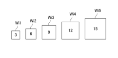
- FIG. 10 is a diagram showing multiple types of virtual workpieces.
- FIG. 11 is a schematic plan view of the inside of the second container 92 to explain the calculation of the evaluation value.
- the virtual work Wi may include multiple types of virtual work Wi with different sizes. When differentiating the types of virtual work Wi, they are distinguished by the number following the symbol "Wi". Specifically, the multiple types of virtual work Wi include a first virtual work Wi1, a second virtual work Wi2, a third virtual work Wi3, a fourth virtual work Wi4, and a fifth virtual work Wi5. The multiple types of virtual work Wi each have a different two-dimensional size. In this example, the multiple types of virtual work Wi each have a substantially square two-dimensional shape with a different area. The first virtual work Wi1 has the smallest two-dimensional square shape. The second virtual work Wi2 has a two-dimensional shape larger than the first virtual work Wi1. The third virtual work Wi3 has a two-dimensional shape larger than the second virtual work Wi2. The fourth virtual work Wi4 has a two-dimensional shape larger than the third virtual work Wi3. The fifth virtual workpiece Wi5 has a larger two-dimensional shape than the fourth virtual workpiece Wi4.
- a different score is assigned to each of the multiple types of virtual work Wi.
- a score corresponding to the size is assigned to each of the multiple types of virtual work Wi. If a large virtual work Wi can be accommodated, it can naturally accommodate a smaller virtual work Wi. Therefore, the larger the area of the two-dimensional shape of the multiple types of virtual work Wi, the higher the score assigned. More specifically, the first virtual work Wi1 is assigned a score of 3 points. The second virtual work Wi2 is assigned a score of 6 points. The third virtual work Wi3 is assigned a score of 9 points. The fourth virtual work Wi4 is assigned a score of 12 points. The fifth virtual work Wi5 is assigned a score of 15 points.
- the evaluator 48 determines how many candidate positions there are for placing the virtual work Wi in the empty space after placing the target work W.
- the evaluator 48 moves the position of the virtual work Wi two-dimensionally by a predetermined amount within the empty space and determines whether the virtual work Wi can be placed without interfering with other objects.
- the evaluator 48 moves the virtual work Wi on the placeable surface P after the target work W is placed in one target position candidate, and determines whether the virtual work Wi can be placed at each position without interfering with other objects. If the virtual work Wi can be placed, the evaluator 48 counts that position as a candidate position. The evaluator 48 moves the virtual work Wi over the entire range of the placeable surface P and counts the number of candidates.
- the evaluator 48 also moves the virtual work Wi to the placeable surface P of the target work W and the existing work W0 and counts the number of candidates.
- the evaluator 48 determines whether the virtual workpiece Wi can be placed on the top surfaces of both works as a uniform placeable surface P.
- the evaluator 48 multiplies the number of candidates by the score assigned to the virtual work Wi to obtain the total score of the virtual work Wi.
- the evaluator 48 calculates the total score of the virtual work Wi for all types of virtual work Wi.
- the evaluator 48 calculates the evaluation value by adding up the total scores of all types of virtual work Wi.
- the evaluator 48 After calculating an evaluation value for one position candidate, the evaluator 48 calculates an evaluation value for when the target work W is placed at another position candidate. Finally, the evaluator 48 calculates evaluation values for all position candidates.
- the evaluation value calculated in this way becomes larger the more large virtual work Wi can be accommodated in the free space. Being able to accommodate more large virtual work Wi means that in the future, more work can be placed with greater freedom. In other words, the evaluation value indicates the efficiency with which virtual work Wi can be accommodated in the free space after the target work W has been placed.
- the determiner 49 determines the position candidate with the highest evaluation value from among the multiple position candidates as the placement target position.
- the path generator 43 generates a target path for the robot arm 12 and hand 14 to transport the target workpiece W to the determined placement target position.
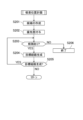
- FIG. 12 is a flowchart of the pick-and-place process.
- step S101 the photography controller 45 acquires an image of the inside of the first container 91. More specifically, the photography controller 45 causes the first camera 51A to acquire an image of the inside of the first container 91.
- step S102 the work detector 41 detects the target work W, specifically the target surface S, from within the image of the first container 91.
- the work detector 41 detects multiple target surfaces S.
- step S103 the position and orientation determiner 42 executes a pickup position plan.
- the pickup position plan the target workpiece W to be picked up by the hand 14 is determined, and the relative position and orientation of the hand 14 with respect to the target workpiece W is also determined.
- a target path for the robot arm 12 and the hand 14 to realize the relative position and orientation of the hand 14 is also generated.
- the motion controller 44 causes the robot arm 12 and hand 14 to execute a picking operation. That is, the motion controller 44 controls the robot arm 12 and hand 14 so that the target workpiece W determined in the suction position plan is picked up at the determined relative position and orientation of the hand 14. Specifically, the motion controller 44 moves the robot arm 12 and hand 14 along the target path, and moves the suction device 15 to the target workpiece W. The motion controller 44 causes the suction device 15 to pick up the target workpiece W.
- step S105 the photography controller 45 captures an image of the inside of the second container 92.
- the photography controller 45 causes the second camera 51B to capture an image of the inside of the second container 92.
- step S106 a place position plan is executed.
- a target place position for the target work W is determined.
- a target path for the robot arm 12 and hand 14 to realize the target place position for the target work W is also generated.
- the motion controller 44 causes the robot arm 12 and hand 14 to execute a placement operation. That is, the motion controller 44 controls the robot arm 12 and hand 14 so that the target work W is placed at the target placement position determined in the placement position plan. Specifically, the motion controller 44 moves the robot arm 12 and hand 14 along the target path to move the target work W to the target placement position. When the target work W reaches the target placement position, the motion controller 44 releases the suction by the suction device 15. In this way, the placement of the target work W at the target placement position is completed. This completes the pick-and-place process.
- the main control device 3 When the main control device 3 completes the pick-and-place process for one target workpiece W, it repeats the process from step S101 to pick-and-place another target workpiece W. By repeating this control, the main control device 3 sequentially transfers the target workpieces W in the first container 91 into the second container 92.
- step S201 the position and orientation determiner 42 creates candidates for the relative position and orientation of the hand 14.
- the position and orientation determiner 42 may create multiple candidates for the relative position and orientation of the hand 14.
- the position and orientation determiner 42 may create multiple candidates for the relative position and orientation of the hand 14 with respect to one target surface S.
- the position and orientation determiner 42 may create candidates for the relative position and orientation of the hand 14 with respect to each target surface S.
- FIG. 14 is a schematic diagram showing the relative position and orientation of the hand 14 when viewed in the direction of the reference axis T.
- the dashed line indicates the offset direction OD of the suction device 15.
- the suction device 15 is located at the suction position of the target surface S, and the reference axis T is approximately perpendicular to the target surface S.
- the position of the reference axis T can take any position within 360 degrees around the suction device 15.
- the position and orientation determiner 42 can create multiple candidates for the relative position and orientation of the hand 14 in which the reference axis T is located at different positions in the circumferential direction around the suction position of the target surface S.
- the suction position is approximately the center of the target surface S.
- the position and orientation determiner 42 can create multiple candidates for the relative position and orientation of the hand 14 in which the target surfaces S are different.
- step S202 the position and orientation determiner 42 assigns priorities to the 14 candidates for the relative position and orientation of the hand. For example, the position and orientation determiner 42 assigns priorities from two perspectives.
- a high priority is given to candidates for the target workpiece W whose reference side does not overlap with the hand 14 when viewed in the direction of the reference axis T, and whose offset direction of the suction device 15 relative to the reference axis T is non-parallel to the reference side.
- the hand 14 picks up the target workpiece W in a state in which the reference axis T and the reference side are relatively far apart when viewed in the direction of the reference axis T.
- the position and orientation determiner 42 sets two reference sides on the target workpiece W.
- the position and orientation determiner 42 sets any two of the sides R1, R2, R3, and R4 of the target workpiece W, specifically, the two sides that are connected to form a corner of the target workpiece W, as the reference sides.
- the position and orientation determiner 42 then assigns a high priority to candidates in which the hand 14 does not overlap either of the two reference sides, and the offset direction of the suction device 15 relative to the reference axis T is non-parallel for both sides.
- the position and orientation determiner 42 may change the reference sides to other two sides, and assign a high priority to candidates that satisfy the above-mentioned conditions for the two changed sides.
- the position and orientation determiner 42 regards the sides of the target surface S as the sides of the target workpiece W.
- the position and orientation determiner 42 assigns a relatively high priority to candidates that satisfy the above-mentioned conditions for each of the two sides that form the four corners of the target surface S, i.e., for a total of four sets of sides.
- the position and orientation determiner 42 then assigns a relatively low priority to the remaining candidates.
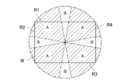
- the position and orientation determiner 42 regards the reference side and the offset direction as non-parallel when the angle between the side as the reference side and the offset direction of the suction device 15 is equal to or greater than a threshold value ⁇ .
- FIG. 15 is a schematic diagram showing an area A where the angle between the side as the reference side and the offset direction of the suction device 15 is equal to or greater than a threshold value ⁇ , and an area B where the angle is less than the threshold value ⁇ .
- a relatively high priority is assigned to candidates whose offset direction of the suction device 15 is included in area A.
- a relatively low priority is assigned to candidates whose offset direction of the suction device 15 is included in area B.
- two reference sides of the target workpiece W may be determined in advance.
- the position and orientation determiner 42 assigns a high priority to a candidate that satisfies the above-mentioned conditions for a set of reference sides, and assigns a low priority to other candidates.
- the position and orientation determiner 42 assigns a high priority to candidates that have a small amount of movement from the current state of the robot arm 12, i.e., the current position. For example, a high priority can be assigned to candidates that have a small total amount of movement of all the joints of the robot arm 12.
- step S203 the position and orientation determiner 42 determines whether or not there is a candidate for the relative position and orientation of the hand 14. If there is no suitable target surface S, it is possible that no candidate for the relative position and orientation of the hand 14 is created in the above-mentioned step S201. In such a case, the pick-and-place process ends in step S206.
- step S204 the position and posture determiner 42 extracts the candidate with the highest priority. Then, the path generator 43 generates a target path for the robot arm 12 from the current position and posture of the hand 14 to the extracted relative position and posture of the hand 14. At this time, the path generator 43 checks for interference with the target path and generates a target path without interference. If interference is present, the path generator 43 does not generate a target path.
- step S205 the position and orientation determiner 42 determines whether or not a target path has been generated. If a target path has not been generated, the position and orientation determiner 42 excludes the extracted candidate for the relative position and orientation of the hand 14 from the candidates, and returns to step S203. The position and orientation determiner 42 again extracts the candidate with the highest priority, and the path generator 43 again generates a target path and performs an interference check.
- the position and orientation determiner 42 extracts candidates in descending order of priority from among the candidates for the relative position and orientation of the hand 14.
- the position and orientation determiner 42 determines the relative position and orientation of the hand 14 and ends the pickup position planning.
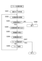
- step S301 the height detector 46 creates a height map of the storage space, i.e., the interior of the second container 92.
- step S302 the searcher 47 searches for multiple position candidates for the placement target position.
- the searcher 47 creates multiple position candidates for the placement target position of the target work W within the second container 92.
- Step S302 corresponds to searching for multiple position candidates that are candidates for the placement target position of the target work in the accommodation space.
- step S303 the searcher 47 determines whether or not there are any position candidates. If there is no space in the second container 92, it is possible that no position candidates are found in step S302. In such a case, the pick-and-place process ends in step S309.
- step S304 the searcher 47 narrows down the location candidates. For example, the searcher 47 selects a location candidate that corresponds to a corner space in the storage space from among multiple location candidates. Note that if there is no location candidate to be narrowed down, the searcher 47 does not narrow down the location candidates.
- step S305 the evaluator 48 calculates an evaluation value for the location candidate. If multiple location candidates are selected in step S304, the evaluator 48 calculates an evaluation value for each of the multiple location candidates. Step S305 corresponds to calculating an evaluation value for each of the multiple location candidates.
- step S306 the path generator 43 generates a target path for the position candidate with the highest evaluation value. That is, the path generator 43 generates a target path for the robot arm 12 and hand 14 from the current position and posture of the robot arm 12 and hand 14 to the position and posture corresponding to the position candidate with the highest evaluation value. At this time, the path generator 43 performs an interference check of the target path to confirm the presence or absence of interference. If interference is present, the path generator 43 excludes the position candidate where interference occurred, and generates a target path for the position candidate with the next highest evaluation value. In this way, the path generator 43 generates target paths from the position candidates in descending order of evaluation value.
- step S307 the determiner 49 determines the place target position to be the position candidate for which an interference-free target route has been generated. This completes the place position planning. Step S307 corresponds to determining the place target position from among the multiple position candidates based on the evaluation value.
- the searcher 47 changes the margin added to the actual size of the target work W when searching for position candidates in step S308, and returns to searching for position candidates in step S302.
- the derived position candidates may change from the previous search. Specifically, the searcher 47 expands the margin. As a result, when searching for position candidates again, the searcher 47 searches for position candidates using a target work W that is larger than the previous time.
- the target work W When the target work W is placed at the place target position determined based on such position candidates, the target work W has a larger margin between it and surrounding objects. Therefore, by using such position candidates in step S306, the possibility of generating a target path without interference is increased. Once the place target position and target path have been generated, the place position planning is completed.
- step S302 If an appropriate target route is still not generated, the margin is further enlarged and the process is repeated from step S302.
- the target placement position is determined based on the future workpiece storage efficiency after the target workpiece W has been placed in the storage space. If the target placement position is determined taking into consideration only the current target workpiece W, there is a risk that the storage efficiency for the target workpiece W from the next time onwards will decrease.
- the main control device 3 calculates an evaluation value based on the available space after the target workpiece W has been placed, and determines the position candidate with the highest evaluation as the target placement position. This makes it possible to realize appropriate placement of multiple workpieces, including not only the current target workpiece W, but also the target workpieces W from the next time onwards.
- Evaluation of the free space can be performed from various perspectives. For example, it may be evaluated how many works can be accommodated in the free space. Or, it may be evaluated how freely the work can be arranged in the free space.
- the evaluation value is related to the efficiency with which the virtual work Wi can be accommodated in the free space. This makes it possible to determine the target placement position so that the efficiency with which the virtual work Wi can be accommodated in the free space after the target work W is placed is high. In other words, it is possible to improve the efficiency with which multiple works can be accommodated from this time onwards.
- the virtual work Wi includes multiple types of virtual work with different sizes, and evaluation values are calculated for the multiple types of virtual work Wi. Therefore, even if work of various sizes is placed in the future, the storage efficiency of these multiple work can be improved.
- the evaluator 48 also treats the top surface of the current target workpiece W as free space. In other words, when the target workpiece W and the existing workpiece W0 are placed side by side, the top surface of the target workpiece W and the top surface of the existing workpiece W0 are exposed upward, and the heights of the top surfaces of the target workpiece W and the existing workpiece W0 are the same, an evaluation value is obtained for those top surfaces as a single placeable surface P. In other words, placing the target workpiece W next to the existing workpiece W0 of the same height tends to expand the free space and increase the evaluation value. In this way, the evaluator 48 can consider not only the planar storage efficiency of the virtual workpiece Wi in the free space, but also the three-dimensional storage efficiency.
- the evaluator 48 also calculates a parameter related to the number of candidate positions at which the virtual work Wi can be placed in the free space as the evaluation value.
- the evaluator 48 can also calculate a parameter related to the capacity of the virtual work Wi that can be placed in the free space as the evaluation value. However, the evaluator 48 can reduce the amount of calculations by using a parameter related to the number of candidate positions at which the virtual work Wi can be placed in the free space.
- the evaluator 48 calculates an evaluation value with priority for the position candidate that corresponds to the corner of the storage space from among multiple position candidates. Placing the work from the corner tends to increase storage efficiency. Therefore, by calculating an evaluation value with priority for the position candidate that corresponds to the corner and determining the placement target position, the amount of calculation can be reduced.
- the relative position and posture of the hand 14 that picks up the target workpiece W is determined so that the reference side of the target workpiece W and the hand 14 do not overlap when viewed in the direction of the reference axis T, and the offset direction of the suction device 15 is non-parallel to the reference side.
- the reference sides are two sides of the target workpiece W that are connected to form an angle.
- the distance between the reference axis T and each of the two reference sides is greater than the distance between the suction device 15 and each of the two reference sides. Therefore, when viewed in the direction of the reference axis T, the tip of the robot arm 12 and the two reference sides are less likely to overlap. As a result, it becomes easier to place the target workpiece W by aligning the corner of the target workpiece W with the corner of the storage space.
- position candidates are searched for based on the size of the target work W, which is the actual size of the target work W enlarged by a predetermined margin. Therefore, the finally determined placement target position has a margin within which the target work W can be displaced.
- the robot arm 12 and hand 14 move the target work W to the placement target position, and then move the target work W laterally to bring the target work W into contact with another object that forms a corner of the storage space. This allows the corner of the target work W to be appropriately aligned with the corner of the storage space.
- the robot system 100 incorporating the main control device 3 is not limited to one that transfers the target work W from the first container 91 to the second container 92.
- the robot 1 may perform debunking.
- the storage location of the target work W is not limited to the second container 92.
- the storage location of the target work W may be a conveyor, a shelf, a pallet, or the like.
- the robot arm 12 is not limited to a vertical multi-joint type robot arm.
- the robot arm 12 may be a horizontal multi-joint type, a parallel link type, a Cartesian coordinate type, or a polar coordinate type robot arm, etc.
- the suction device 15 does not have to rotate around the reference axis T relative to the robot arm 12. Even if the suction device 15 cannot rotate around the reference axis T, it only needs to be positioned at a position offset in the radial direction around the reference axis T of the robot arm 12, that is, positioned eccentrically with respect to the reference axis T.
- the suction device 15 may attract the workpiece by magnetic force or the like instead of negative pressure.
- the camera 51 does not have to include a first camera 51A and a second camera 51B.
- a single camera 51 may capture an image of the inside of the first container 91 and an image of the inside of the second container 92.
- the camera 51 does not have to be fixedly disposed, but may be attached to the robot arm 12 and moved by the robot arm 12.
- the robot system 100 may not be equipped with a camera 51. In that case, an image may be input to the main control device 3 from outside. The method of acquiring the image is not important. The image input from outside may be stored in the memory 33 or in the storage device 32.
- the target work to be picked may not be piled up randomly, but may be aligned.
- the target work is not limited to a rectangular parallelepiped work.
- the target work may have a shape of a roughly triangular prism.
- the target work may be a bag filled with powder or granular material such as fertilizer, lime, gravel, etc.
- the processing by the work detector 41, the position and orientation determiner 42, the operation controller 44, and the imaging controller 45 is merely an example.
- the work detector 41 can detect the target surface S from the image using various methods.
- the position and orientation determiner 42 can determine the relative position and orientation of the hand 14 using various methods.
- the reference side of the target workpiece is not limited to a flat surface. If the target workpiece is a bag-shaped workpiece, the part facing to the side of the suction surface that the suction device 15 comes into contact with can be the reference side.
- the position and orientation determiner 42 may also approximate the target workpiece to a rectangular parallelepiped, with one face of the approximate rectangular parallelepiped as the suction surface, and the face that is a side face of the suction surface as the reference side.
- the position and orientation determiner 42 may approximate the target workpiece by an OBB (Oriented Bounding Box).
- the position and orientation determiner 42 may execute the pickup position plan after the place position plan.
- the position and orientation determiner 42 can determine the relative position and orientation of the hand 14 at the time of picking based on the previously determined place target position. For example, when the place target position is a position corresponding to a corner of the storage space, the two sides of the target work W that come into contact with the two side surfaces that form the corner are determined in advance. The position and orientation determiner 42 determines the relative position and orientation of the hand 14 using the two sides as the reference sides.
- the position and posture determiner 42 does not need to create as candidates the relative position and posture of the hand 14 in which the reference side of the target work W and the hand 14 overlap when viewed in the direction of the reference axis T, or the relative position and posture of the hand 14 in which the offset direction of the suction device 15 is parallel to the reference side when viewed in the direction of the reference axis T.
- the position and posture determiner 42 may create as candidates only the relative position and posture of the hand 14 in which the reference side of the target work W and the hand 14 do not overlap when viewed in the direction of the reference axis T, and the offset direction of the suction device 15 relative to the reference axis T is non-parallel to the reference side.
- the determination of the relative position and posture of the hand 14 by the position and posture determiner 42 is merely one preferred example, and the reference side of the target workpiece W and the hand 14 may overlap when viewed in the direction of the reference axis T, or the offset direction of the suction device 15 may be parallel to the reference side when viewed in the direction of the reference axis T.
- the processing of the searcher 47, the evaluator 48, or the determiner 49 is merely an example.
- the searcher 47 may narrow down the multiple position candidates in stages. As described above, if the place target position cannot be determined by narrowing down the position candidates to those corresponding to corners, the remaining position candidates may be narrowed down to those that contact the side surfaces within the storage space. Alternatively, the searcher 47 may narrow down the multiple position candidates to both the position candidates that correspond to corners and the position candidates that contact the side surfaces at the same time. The searcher 47 does not have to narrow down the multiple position candidates.
- the searcher 47 When searching for position candidates, the searcher 47 adds a predetermined margin to the actual size of the target work W, but is not limited to this. The searcher 47 may also search for position candidates using the actual size of the target work W.
- the evaluator 48 may calculate a parameter related to the number of virtual works Wi that can be placed in the free space as the evaluation value. In other words, the evaluator 48 may adjust the arrangement of the virtual works Wi in the free space to determine the maximum number of virtual works Wi that can be accommodated in the free space for each of the multiple types of virtual works Wi. The evaluator 48 may multiply each virtual work Wi by a score corresponding to the maximum number of each virtual work Wi to calculate a total score for each virtual work Wi, and use the sum of these as the evaluation value.
- the virtual work Wi may not include multiple types of virtual work Wi.
- the evaluator 48 may calculate the evaluation value using a single type of virtual work Wi.
- the number of types is not limited to 5.
- the number of types may be 2, 3, 4, or 6 or more.
- the two-dimensional shape of the virtual workpiece Wi is not limited to a square.
- the two-dimensional shape of the virtual workpiece Wi may be the known workpiece shape.
- the above-mentioned scores assigned to each of the multiple types of virtual work Wi are merely one example.
- the evaluation value may be set arbitrarily. The evaluation value may be set so that the higher the evaluation, the smaller the value.
- a higher score may be assigned to a virtual work Wi that is assumed to have a higher actual frequency.
- the control device does not have to be a single device like the main control device 3.
- the control device may include multiple separate devices.
- the work detector 41, the position and orientation determiner 42, and the motion controller 44 may each be realized by separate devices.
- the flowchart is merely an example. Steps in the flowchart may be changed, replaced, added, omitted, etc. as appropriate. The order of steps in the flowchart may also be changed, and serial processing may be performed in parallel. For example, photographing the interior of the second container 92 in step S105 of FIG. 12 and planning the placement position in step S106 may be performed any time before the placement operation. Specifically, photographing the interior of the second container 92 and planning the placement position may be performed prior to or in parallel with the pickup position planning, etc.
- a processor includes transistors and other circuits and is considered a circuit or processing circuit.
- a processor may be a programmable processor that executes a program stored in a memory.
- a circuit, unit, or means is hardware that is programmed to realize or executes the described functions.
- the hardware may be any hardware disclosed in this specification or any hardware known to be programmed to realize or execute the described functions.
- the hardware is a processor that is considered to be a type of circuitry
- the circuit, means, or unit is a combination of hardware and software used to configure the hardware and/or processor.
- the main control device 3 (control device) includes a searcher 47 that searches for multiple position candidates that are candidates for the target placement position of the target work W in the storage space, an evaluator 48 that calculates an evaluation value for each of the multiple position candidates, and a determiner 49 that determines the target placement position from among the multiple position candidates based on the evaluation value, and the evaluator 48 calculates the evaluation value based on the vacant space in the storage space after the target work W is placed at each of the position candidates.
- the placement target position is determined based on the space available after the target work W has been placed. This allows the placement target position to be determined taking into consideration the placement of subsequent work after the target work W has been placed. As a result, it is possible to realize appropriate placement of multiple workpieces, including not only the current target work W, but also subsequent workpieces.
- the evaluation value is a parameter indicating the efficiency with which the virtual work Wi can be accommodated in the free space.
- the placement target position is determined based on the accommodation efficiency of the virtual work Wi in the vacant space after the target work W has been placed. This allows the placement target position to be determined taking into consideration how efficiently the virtual work Wi can be placed in the vacant space after the target work W has been placed. As a result, it is possible to improve the accommodation efficiency of multiple works to be placed in the future.
- the evaluation value is a parameter related to the number of virtual works Wi that can be placed in the free space or the number of candidate positions where the virtual works Wi can be placed in the free space.
- the placement target position is determined based on the capacity of the virtual work Wi in the vacant space after the target work W has been placed.
- the capacity of the virtual work Wi directly indicates the capacity of the virtual work Wi.
- the number of candidate positions at which the virtual work Wi can be placed is related to the capacity of the virtual work Wi. This allows the placement target position to be determined taking into account how many virtual works Wi can be placed in the vacant space after the target work W has been placed. As a result, the capacity efficiency of multiple works to be placed in the future can be improved.
- the virtual work Wi includes multiple types of virtual work with different sizes, different scores are assigned to the multiple types of virtual work, and the evaluator 48 calculates the evaluation value according to the number of storage spaces or the number of candidates and the score.
- the efficiency of accommodating virtual work Wi in free space is evaluated taking into account differences in the size of the virtual work.
- differences in the size of the virtual work can be taken into account.
- the efficiency of accommodating multiple works can be improved by taking into account variations in the size of works to be placed in the future.
- the evaluator 48 calculates the evaluation value by regarding the space above the exposed part of the bottom surface of the storage space and the space above the exposed part of the top surface of the existing work W0 in the storage space as the free space.
- the evaluator 48 evaluates not only the bottom surface of the storage space, but also the space above the top surface of the existing work W0 as space in which to place the virtual work Wi. As a result, it is possible to take into account not only the planar storage efficiency of the virtual work Wi in the free space, but also the three-dimensional storage efficiency.
- the evaluator 48 calculates the evaluation value by treating the top surface of the target work W and the top surface of the existing work W0 as a single surface.
- the top surface of the target work W and the top surface of the existing work W0 which are aligned at the same height, are treated as a single surface, which contributes to improving the storage efficiency of the virtual work Wi.
- Placing the target work W so that its height is aligned with the existing work W0 tends to result in a higher evaluation value.
- the placement target position is determined taking into consideration how much of the virtual work Wi can be placed on the top surface of the target work W after it has been placed.
- the searcher 47 searches for the position candidate corresponding to a corner included in the storage space.
- This configuration can reduce the amount of calculation of the evaluation value. More specifically, when storing the target work W in a storage space, it is preferable from the standpoint of work storage efficiency to place the target work W tightly in a space that includes a corner. Ultimately, the storage efficiency of the virtual work Wi in an empty space is often high when the target work W is placed in a space that includes a corner. By narrowing down the position candidates for the placement target position in advance to those that correspond to corners included in the storage space, it is possible to omit the calculation of the evaluation value for the less likely position candidates. As a result, the amount of calculation of the evaluation value can be reduced.
- the robot system 100 includes a robot 1 having a robot arm 12 and a hand 14 attached to the robot arm 12, and a main control device 3 described in any one of [1] to [7].
- the placement target position is determined based on the space available after the target work W has been placed. This allows the placement target position to be determined taking into consideration the placement of subsequent work after the target work W has been placed. As a result, it is possible to realize appropriate placement of multiple workpieces, including not only the current target work W, but also subsequent workpieces.
- the placement target position is determined based on the space available after the target work W has been placed. This allows the placement target position to be determined taking into consideration the placement of subsequent work after the target work W has been placed. As a result, it is possible to realize appropriate placement of multiple workpieces, including not only the current target work W, but also subsequent workpieces.
- Robot system 100 Robot system 1 Robot 12 Robot arm 14 Hand 3 Main control device (control device) 47 Searcher 48 Evaluator 49 Decision device W Target work
Landscapes
- Engineering & Computer Science (AREA)
- Robotics (AREA)
- Mechanical Engineering (AREA)
- Manipulator (AREA)
Abstract
Description
ロボット1は、ロボットアーム12及びロボットアーム12に取り付けられたハンド14を有する。ロボット1は、この例では、産業用ロボットである。ハンド14は、いわゆるエンドエフェクタである。ロボット1が配置される空間には、直交3軸のベース座標系が規定されている。
次に、吸着位置計画について詳しく説明する。図13は、吸着位置計画のサブルーチンのフローチャートである。
次に、プレース位置計画について詳しく説明する。図16は、プレース位置計画のサブルーチンのフローチャートである。
以上のように、本出願において開示する技術の例示として、前記実施形態を説明した。しかしながら、本開示における技術は、これに限定されず、適宜、変更、置き換え、付加、省略などを行った実施の形態にも適用可能である。また、前記実施形態で説明した各構成要素を組み合わせて、新たな実施の形態とすることも可能である。また、添付図面および詳細な説明に記載された構成要素の中には、課題解決のために必須な構成要素だけでなく、前記技術を例示するために、課題解決のためには必須でない構成要素も含まれ得る。そのため、それらの必須ではない構成要素が添付図面や詳細な説明に記載されていることをもって、直ちに、それらの必須ではない構成要素が必須であるとの認定をするべきではない。
1 ロボット
12 ロボットアーム
14 ハンド
3 主制御装置(制御装置)
47 探索器
48 評価器
49 決定器
W 対象ワーク
Claims (9)
- 収容スペースにおける対象ワークのプレース目標位置の候補である複数の位置候補を探索する探索器と、
複数の前記位置候補のそれぞれの評価値を算出する評価器と、
複数の前記位置候補の中から前記評価値に基づいて前記プレース目標位置を決定する決定器とを備え、
前記評価器は、それぞれの前記位置候補に前記対象ワークがプレースされた後の前記収容スペース内の空きスペースに基づいて前記評価値を算出する制御装置。 - 請求項1に記載の制御装置において、
前記評価値は、前記空きスペースへの仮想ワークの収容効率を示すパラメータである制御装置。 - 請求項1に記載の制御装置において、
前記評価値は、前記空きスペースにプレースできる仮想ワークの収容数又は前記空きスペースに仮想ワークをプレースできる位置の候補数に関連するパラメータである制御装置。 - 請求項3に記載の制御装置において、
前記仮想ワークは、大きさの異なる複数種類の仮想ワークを含み、
前記複数種類の仮想ワークのそれぞれには、異なるスコアが割り当てられ、
前記評価器は、前記収容数又は前記候補数と前記スコアに応じて前記評価値を算出する制御装置。 - 請求項1に記載の制御装置において、
前記評価器は、前記収容スペースの底面のうち露出する部分の上のスペース及び前記収容スペースにおける既存のワークの上面のうち露出する部分の上のスペースを前記空きスペースとして前記評価値を算出する制御装置。 - 請求項5に記載の制御装置において、
前記評価器は、前記対象ワークと前記既存のワークとが並び、前記対象ワークの上面及び前記既存のワークの上面とが露出し、且つ、前記対象ワークの上面と前記既存のワークの上面との高さが揃っている場合に、前記対象ワークの上面及び前記既存のワークの上面を単一の面として前記評価値を算出する制御装置。 - 請求項1に記載の制御装置において、
前記探索器は、前記収容スペースに含まれる角に対応する前記位置候補を探索する制御装置。 - ロボットアームと前記ロボットアームに取り付けられたハンドとを有するロボットと、
請求項1乃至7の何れか1つに記載の制御装置とを備えるロボットシステム。 - ロボットアームと前記ロボットアームに取り付けられたハンドとを有するロボットの制御方法であって、
収容スペースにおける対象ワークのプレース目標位置の候補である複数の位置候補を探索することと、
複数の前記位置候補のそれぞれの評価値を算出することと、
複数の前記位置候補の中から前記評価値に基づいて前記プレース目標位置を決定することとを含み、
前記評価値を算出することは、それぞれの前記位置候補に前記対象ワークがプレースされた後の前記収容スペース内の空きスペースに基づいて前記評価値を算出するロボットの制御方法。
Priority Applications (2)
| Application Number | Priority Date | Filing Date | Title |
|---|---|---|---|
| JP2025523767A JPWO2024247136A1 (ja) | 2023-05-30 | 2023-05-30 | |
| PCT/JP2023/020185 WO2024247136A1 (ja) | 2023-05-30 | 2023-05-30 | 制御装置、ロボットシステム及びロボットの制御方法 |
Applications Claiming Priority (1)
| Application Number | Priority Date | Filing Date | Title |
|---|---|---|---|
| PCT/JP2023/020185 WO2024247136A1 (ja) | 2023-05-30 | 2023-05-30 | 制御装置、ロボットシステム及びロボットの制御方法 |
Publications (1)
| Publication Number | Publication Date |
|---|---|
| WO2024247136A1 true WO2024247136A1 (ja) | 2024-12-05 |
Family
ID=93657091
Family Applications (1)
| Application Number | Title | Priority Date | Filing Date |
|---|---|---|---|
| PCT/JP2023/020185 Ceased WO2024247136A1 (ja) | 2023-05-30 | 2023-05-30 | 制御装置、ロボットシステム及びロボットの制御方法 |
Country Status (2)
| Country | Link |
|---|---|
| JP (1) | JPWO2024247136A1 (ja) |
| WO (1) | WO2024247136A1 (ja) |
Citations (2)
| Publication number | Priority date | Publication date | Assignee | Title |
|---|---|---|---|---|
| JP2020196611A (ja) * | 2019-05-31 | 2020-12-10 | 株式会社Mujin | リアルタイム載置シミュレーションを使用してパッケージをパレタイズするためのロボットシステム |
| CN113183156A (zh) * | 2021-05-17 | 2021-07-30 | 广东工业大学 | 一种基于数字孪生技术的智能码垛方法 |
-
2023
- 2023-05-30 WO PCT/JP2023/020185 patent/WO2024247136A1/ja not_active Ceased
- 2023-05-30 JP JP2025523767A patent/JPWO2024247136A1/ja active Pending
Patent Citations (2)
| Publication number | Priority date | Publication date | Assignee | Title |
|---|---|---|---|---|
| JP2020196611A (ja) * | 2019-05-31 | 2020-12-10 | 株式会社Mujin | リアルタイム載置シミュレーションを使用してパッケージをパレタイズするためのロボットシステム |
| CN113183156A (zh) * | 2021-05-17 | 2021-07-30 | 广东工业大学 | 一种基于数字孪生技术的智能码垛方法 |
Also Published As
| Publication number | Publication date |
|---|---|
| JPWO2024247136A1 (ja) | 2024-12-05 |
Similar Documents
| Publication | Publication Date | Title |
|---|---|---|
| CN111504328B (zh) | 机器人运动规划方法、路径规划方法、抓取方法及其装置 | |
| US11498210B2 (en) | Object handling device and computer program product | |
| US11383380B2 (en) | Object pickup strategies for a robotic device | |
| JP7015031B2 (ja) | カメラによって生成される画像情報に基づいて、物体検出またはロボット相互作用計画作成を行う方法および計算システム | |
| CN113811882A (zh) | 检测盒子 | |
| JP7191569B2 (ja) | 把持装置 | |
| JP7454132B2 (ja) | ロボットシステムの制御装置、ロボットシステムの制御方法、コンピュータ制御プログラム、及びロボットシステム | |
| JP6950638B2 (ja) | マニピュレータ制御装置、マニピュレータ制御方法、及びマニピュレータ制御プログラム | |
| JP7708840B2 (ja) | ロボットの構成部材の干渉を検出するロボット装置 | |
| EP4094904B1 (en) | Robot system control device, robot system control method, computer control program, and robot system | |
| CN110587592A (zh) | 机器人控制装置、机器人控制方法及计算机可读记录介质 | |
| JP2018008343A (ja) | 部品ピックアップ方法及び部品供給装置 | |
| CN115485217A (zh) | 设定堆叠工件的位置的位置设定装置和具备位置设定装置的机器人装置 | |
| JP2012135820A (ja) | 自動ピッキング装置及び自動ピッキング方法 | |
| JP7842202B2 (ja) | ロボットシステム | |
| JP7792267B2 (ja) | 対象物をピックアップするロボットの制御装置及び制御方法並びにコンピュータプログラム及びコンピュータ可読媒体 | |
| Janabi-Sharifi et al. | Automatic grasp planning for visual-servo controlled robotic manipulators | |
| JP2021091056A (ja) | 測定装置 | |
| WO2024247134A1 (ja) | 制御装置、ロボットシステム及びロボットの制御方法 | |
| WO2024247135A1 (ja) | 制御装置、ロボットシステム及びロボットの制御方法 | |
| US20260124767A1 (en) | Control apparatus and control method | |
| WO2024143417A1 (ja) | 物体検出装置、ロボットシステム及び物体検出方法 | |
| WO2024166293A1 (ja) | 制御装置、ロボットシステム、ロボットの制御方法 | |
| WO2025141860A1 (ja) | 制御装置、ロボットシステム及び動作計画方法 |
Legal Events
| Date | Code | Title | Description |
|---|---|---|---|
| 121 | Ep: the epo has been informed by wipo that ep was designated in this application |
Ref document number: 23939614 Country of ref document: EP Kind code of ref document: A1 |
|
| ENP | Entry into the national phase |
Ref document number: 2025523767 Country of ref document: JP Kind code of ref document: A |
|
| WWE | Wipo information: entry into national phase |
Ref document number: 2025523767 Country of ref document: JP |
|
| NENP | Non-entry into the national phase |
Ref country code: DE |
|
| 122 | Ep: pct application non-entry in european phase |
Ref document number: 23939614 Country of ref document: EP Kind code of ref document: A1 |