WO2024247114A1 - 劣化診断装置、劣化診断システム、劣化推定学習装置および劣化診断方法 - Google Patents
劣化診断装置、劣化診断システム、劣化推定学習装置および劣化診断方法 Download PDFInfo
- Publication number
- WO2024247114A1 WO2024247114A1 PCT/JP2023/020114 JP2023020114W WO2024247114A1 WO 2024247114 A1 WO2024247114 A1 WO 2024247114A1 JP 2023020114 W JP2023020114 W JP 2023020114W WO 2024247114 A1 WO2024247114 A1 WO 2024247114A1
- Authority
- WO
- WIPO (PCT)
- Prior art keywords
- deterioration
- unit
- eccentricity
- degree
- deterioration diagnosis
- Prior art date
- Legal status (The legal status is an assumption and is not a legal conclusion. Google has not performed a legal analysis and makes no representation as to the accuracy of the status listed.)
- Ceased
Links
Images






Classifications
-
- G—PHYSICS
- G01—MEASURING; TESTING
- G01R—MEASURING ELECTRIC VARIABLES; MEASURING MAGNETIC VARIABLES
- G01R31/00—Arrangements for testing electric properties; Arrangements for locating electric faults; Arrangements for electrical testing characterised by what is being tested not provided for elsewhere
- G01R31/34—Testing dynamo-electric machines
Definitions
- This technology relates to a deterioration diagnosis device, deterioration diagnosis system, deterioration estimation learning device, and deterioration diagnosis method for diagnosing the deterioration of equipment.
- it relates to diagnosing the deterioration of a rotating shaft of equipment.
- Equipment equipped with an electric motor such as a compressor that constitutes a refrigeration cycle device, has a rotating shaft (hereafter referred to as the shaft) that transmits power from the motor and bearings that support the shaft.
- the shaft a rotating shaft
- the cause of the compressor's failure is often due to deterioration or damage of the bearings. If the equipment is operated with the bearings worn out and deteriorated, the motor will stop, causing significant downtime in the operation of the compressor and reducing the operating rate of the compressor.
- a deterioration diagnosis device has been proposed that creates a Lissajous figure distribution diagram by overlapping two types of current data obtained by a current measurement unit for multiple periods, and diagnoses the condition of a rotating machine system based on the evaluation results of the distribution diagram (see, for example, Patent Document 1).
- the objective is to provide a deterioration diagnosis device, a deterioration diagnosis system, a deterioration estimation learning device, and a deterioration diagnosis method that can perform deterioration diagnosis of rotating shafts with higher accuracy.
- the disclosed deterioration diagnosis device is a deterioration diagnosis device that diagnoses the progression of deterioration in equipment equipped with an electric motor, and includes a dynamic eccentricity estimation unit that estimates the degree of dynamic eccentricity of a rotating shaft that constitutes the equipment based on the current flowing through the electric motor, and a deterioration diagnosis unit that diagnoses the degree of shaft deterioration of the rotating shaft based on the estimation result.
- the disclosed degradation diagnosis system also includes a recording device that records data related to the equipment in which the electric motor is mounted, which data is included in a signal sent via a telecommunications line, and the above-mentioned degradation diagnosis device that diagnoses the degree of shaft deterioration related to the rotating shaft that constitutes the equipment, based on data related to the current flowing through the equipment recorded by the recording device.
- the disclosed degradation estimation learning device is a degradation estimation learning device that learns to estimate degradation in equipment equipped with an electric motor, and includes a learning unit that performs a learning process using machine learning based on data on the current flowing through the electric motor according to the driving frequency of the electric motor and data on the corresponding amount of degradation, and generates a learned model that estimates the degree of dynamic eccentricity of a rotating shaft that constitutes the equipment, and a memory unit that stores the generated learned model.
- the disclosed deterioration diagnosis method is a deterioration diagnosis method for diagnosing the progression of deterioration in equipment equipped with an electric motor, and includes a dynamic eccentricity estimation process for estimating the degree of dynamic eccentricity of a rotating shaft that constitutes the equipment based on the current flowing through the electric motor, and a deterioration diagnosis process for diagnosing the degree of shaft deterioration of the rotating shaft based on the estimation result.
- FIG. 1 is a diagram illustrating an example of the configuration of a degradation diagnosis system SYS1 according to a first embodiment.
- FIG. 2 is a diagram illustrating an example of an internal configuration of a compressor 5 according to the first embodiment.
- FIG. 5A to 5C are diagrams illustrating the state of a main shaft 52 and a main bearing 57 when the compressor 5 according to the first embodiment is driven.
- 2 is a block diagram showing a configuration of a degradation diagnosis unit 100 in the control device 10 according to the first embodiment.
- FIG. 3 is a block diagram showing a configuration of a static eccentricity estimation unit 110 in the degradation diagnosis unit 100 according to the first embodiment.
- FIG. 4 is a block diagram showing a configuration of a dynamic eccentricity estimation unit 120 in the deterioration diagnosis unit 100 according to the first embodiment.
- FIG. 13 is a diagram showing a U-phase current Iu and an envelope Env of the U-phase current Iu.
- FIG. FIG. 11 is a diagram showing an example of an image in which the degree of shaft deterioration in the dynamic eccentricity estimation process is expressed by the dynamic eccentricity estimating unit 120 according to the first embodiment, using frequency characteristics.
- 4 is a diagram illustrating a flow of degradation diagnosis processing by a degradation diagnosis unit 100 according to the first embodiment.
- FIG. 4 is a diagram for explaining the flow of shaft deterioration determination processing performed by a shaft deterioration diagnosis unit 130 according to the first embodiment.
- FIG. 10 is a diagram illustrating thresholds in the shaft deterioration determination process performed by the shaft deterioration diagnosis unit 130 according to the first embodiment.
- FIG. 11 is a block diagram showing configurations of a degradation diagnosis unit 100 and a degradation estimation learning unit 200 in a control device 10 according to embodiment 2.
- FIG. 13 is a diagram illustrating the flow of processing by the degradation estimation learning unit 200 according to the second embodiment.
- FIG. 11 is a diagram showing a process flow in an inference unit 125 of a dynamic eccentricity estimating unit 120 according to the second embodiment.
- FIG. 11 is a block diagram showing a configuration of a shaft deterioration diagnosis unit 130 according to a third embodiment.
- 13 is a diagram illustrating thresholds in the shaft deterioration determination process performed by the shaft deterioration diagnosis unit 130 according to the third embodiment.
- FIG. FIG. 13 is a block diagram illustrating a configuration example of a degradation diagnosis system SYS2 according to a fourth embodiment.
- deterioration diagnosis device deterioration diagnosis system
- learning device deterioration diagnosis method according to the embodiments
- deterioration diagnosis method according to the embodiments will be described with reference to the drawings.
- components with the same reference numerals in each drawing are the same or equivalent components, and are common to all the embodiments described below.
- the forms of the components shown in all the embodiments described below are merely examples, and are not limited to the forms described below.
- the combinations of the components are not limited to the combinations in each embodiment, and the components described in other embodiments can be applied to other embodiments.
- the level of parameters such as pressure and temperature is not determined in relation to an absolute value, but is determined relatively in the state and operation of the device, etc.
- Fig. 1 is a diagram for explaining a configuration example of a degradation diagnosis system SYS1 according to embodiment 1.
- the degradation diagnosis system SYS1 according to embodiment 1 will be explained with reference to Fig. 1 and other figures.
- a control device 10 serves as a degradation diagnosis device and performs degradation diagnosis processing on a device to be diagnosed.
- a compressor 5 having an electric motor 53 and used in a refrigeration cycle device or the like serves as the device to be diagnosed.
- the configuration of the compressor 5 will be described later.
- the compressor 5 is driven at a predetermined drive frequency by components including an AC power source 1, a rectifier circuit 2, an electrolytic capacitor 3, and an inverter circuit 4.
- the rectifier circuit 2 converts three-phase (U-phase, V-phase, and W-phase) AC power from the AC power source 1 into DC power.
- the electrolytic capacitor 3 smoothes the DC power from the rectifier circuit 2.
- the inverter circuit 4 converts the DC power from the rectifier circuit 2 into three-phase AC power based on the drive frequency, and supplies the three-phase AC power to the compressor 5.
- the current sensor 6 is provided midway along the wiring 7 leading from the inverter circuit 4 to the compressor 5.
- the current sensor 6 detects two phase currents of the three-phase AC current flowing from the inverter circuit 4 to the compressor 5 based on a predetermined drive frequency.
- the current sensor 6 detects, for example, the U-phase current Iu and the V-phase current Iv, and sends them to the control device 10 as a current detection signal Iuv.
- the voltage sensor 8 detects the bus voltage. The voltage detected by the voltage sensor 8 is sent to the control device 10 as a voltage detection signal Vdc.
- control device 10 is a component that drives the compressor 5.
- the control device 10 outputs a gate pulse GP to the inverter circuit 4 based on the current detection signal Iuv related to the detection of the current sensor 6 and the voltage detection signal Vdc related to the detection of the voltage sensor 8, and controls the driving of the compressor 5.
- the control device 10 has hardware such as a computer that executes various programs, and realizes various processes such as control processing and degradation diagnosis processing.
- the computing entity in the hardware is, for example, a processing device 11 such as a CPU (Central Processing Unit) or an FPGA (Field-Programmable Gate Array).
- the processing performed by the control device 10 is realized when the processing device 11 executes processing based on the data of the program stored in the storage device 12.
- the storage device 12 has a volatile storage device (not shown) such as a random access memory (RAM) that can temporarily store data, and a non-volatile auxiliary storage device (not shown) such as a flash memory that can store data for a long period of time.
- the storage device 12 stores the program that the processing device 11 performs processing. In the following, the processing and storage performed by the processing device 11 and the storage device 12 will be described as being performed by the control device 10.
- the control device 10 in embodiment 1 has a deterioration diagnosis unit 100. Therefore, the control device 10 in embodiment 1 functions as a deterioration diagnosis device.
- the deterioration diagnosis unit 100 performs diagnosis processing for deterioration related to the relationship between the main shaft 52 and the main bearing 57 in the compressor 5 described below, such as damage to the main bearing 57, based on the current detection signal Iuv related to the detection of the current sensor 6, and outputs a diagnosis result signal including a shaft deterioration diagnosis result SWR.
- the configuration and processing contents related to the processing function of the deterioration diagnosis unit 100 will be described later.
- the deterioration related to the relationship between the main shaft 52 and the main bearing 57 will be described below as shaft deterioration.
- the notification device 20 is a device that issues notifications based on a signal from the control device 10.
- the notification device 20 has a display device, and displays based on the diagnosis result signal including the shaft deterioration diagnosis result SWR output by the deterioration diagnosis unit 100, and notifies the user or maintenance team, etc., of the degree of shaft deterioration.
- FIG. 2 is a diagram illustrating the internal configuration of an example of the compressor 5 according to the first embodiment.
- the compressor 5 has a suction pipe 51, a main shaft 52, an electric motor 53, lubricating oil 54, an oil pump 55, an auxiliary bearing 56, a main bearing 57, a compression mechanism 58, and a discharge pipe 59.
- the compressor 5 is a device that constitutes part of a refrigerant circuit in a refrigeration cycle device such as an air conditioner. In the compressor 5, the refrigerant is sucked in through the suction pipe 51 of the compressor 5 and discharged from the discharge pipe 59.
- the suction pipe 51 is a pipe for sucking low-temperature, low-pressure refrigerant into the compressor 5.
- a pressure sensor, a temperature sensor, a humidity sensor, etc. may be attached to the suction pipe 51 to measure the pressure, temperature, humidity, etc. of the refrigerant flowing inside the pipe.
- these sensors may be attached to the piping in the refrigerant circuit to estimate the pressure, temperature, humidity, etc. of the refrigerant flowing inside the suction pipe 51.
- the discharge pipe 59 is a pipe for discharging the high-temperature, high-pressure refrigerant compressed by the compression mechanism 58 to the outside of the compressor 5.
- a pressure sensor, a temperature sensor, a humidity sensor, etc. may be attached to the discharge pipe 59 to detect the pressure, temperature, humidity, etc. of the refrigerant flowing inside the pipe.
- these sensors may be attached to the piping inside the air conditioning equipment to estimate the pressure, temperature, humidity, etc. of the refrigerant flowing inside the discharge pipe 59.
- FIG. 3 is a diagram explaining the state of the main shaft 52 and the main bearing 57 when the compressor 5 according to the first embodiment is driven.
- FIG. 3(a) is a diagram showing a cross section when the main shaft 52 and the main bearing 57 are in a lubricated state and the compressor 5 is operating normally.
- FIG. 3(b) and FIG. 3(c) are diagrams showing cross sections when the main shaft 52 and the main bearing 57 are not in a lubricated state and the shaft is deteriorated.
- a state in which the main shaft 52 continues to rotate in an eccentric manner at a certain position within the main bearing 57 is said to be static eccentricity.
- a state in which the main shaft 52 continues to rotate within the main bearing 57 while rotating around it at each mechanical angle cycle is said to be dynamic eccentricity.
- the static eccentricity shown in Figure 3(b) and the dynamic eccentricity shown in Figure 3(c) are influenced by the installation environment and load state of the compressor 5, and eccentricity may occur either one at a time or simultaneously, accelerating shaft deterioration and reducing the operating rate of the compressor 5.
- FIG. 4 is a block diagram showing the configuration of the deterioration diagnosis unit 100 in the control device 10 according to the first embodiment.
- the control device 10 becomes a deterioration diagnosis device by having the deterioration diagnosis unit 100.
- the deterioration diagnosis unit 100 performs deterioration diagnosis processing and outputs a diagnosis result signal including the shaft deterioration diagnosis result SWR.
- the deterioration diagnosis unit 100 in the first embodiment has a static eccentricity estimation unit 110, a dynamic eccentricity estimation unit 120, and a shaft deterioration diagnosis unit 130.
- the static eccentricity estimation unit 110 performs a static eccentricity estimation process to calculate the degree of static eccentricity from the U-phase current Iu and the V-phase current Iv, and outputs a static eccentricity ratio UF as the estimation result.
- the static eccentricity estimation unit 110 will be described in detail later.
- the dynamic eccentricity estimation unit 120 performs a dynamic eccentricity estimation process to calculate the degree of dynamic eccentricity from the U-phase current Iu, and outputs a dynamic eccentricity ratio West as the estimation result.
- the dynamic eccentricity estimation unit 120 will also be described in detail later.
- the shaft deterioration diagnosis unit 130 performs a deterioration diagnosis process to diagnose the degree of shaft deterioration related to the spindle 52 from the static eccentricity ratio UF and the dynamic eccentricity ratio West, and outputs a diagnosis result signal including the shaft deterioration diagnosis result SWR to the notification device 20.
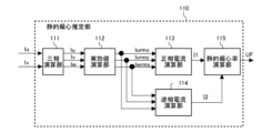
- FIG. 5 is a block diagram showing the configuration of the static eccentricity estimation unit 110 in the deterioration diagnosis unit 100 according to the first embodiment.
- the static eccentricity estimation unit 110 has a three-phase calculation unit 111, an effective value calculation unit 112, a positive-sequence current calculation unit 113, a negative-sequence current calculation unit 114, and a static eccentricity rate calculation unit 115.
- the three-phase calculation unit 111 calculates the W-phase current Iw from the currents of two phases (here, the U-phase current Iu and the V-phase current Iv) of the three-phase AC current based on equation (1).
- the effective value calculation unit 112 calculates the effective values (U-phase effective value Iurms, V-phase effective value Ivrms, and W-phase effective value Ivrms) of the three-phase currents (U-phase current Iu, V-phase current Iv, and W-phase current Iw) from the three-phase calculation unit 111.
- the positive-phase current calculation unit 113 calculates the positive-phase current I1 based on equations (2) and (3).
- the negative-phase current calculation unit 114 calculates the negative-phase current I2 based on equations (2) and (4).
- the static eccentricity calculation unit 115 calculates the static eccentricity UF from the positive-phase current I1 and the negative-phase current I2 based on equation (5).
- the static eccentricity estimation unit 110 calculates the static eccentricity factor UF from the ratio of the positive-phase current I1 to the negative-phase current I2. Therefore, the static eccentricity estimation unit 110 can estimate the degree of shaft deterioration for various models. By estimating the degree of shaft deterioration from the static eccentricity factor UF, it is possible to improve the reliability of the compressor 5 and the refrigeration cycle device equipped with the compressor 5. This makes it possible to provide better service to users.
- FIG. 6 is a block diagram showing the configuration of the dynamic eccentricity estimation unit 120 in the deterioration diagnosis unit 100 according to the first embodiment.
- the dynamic eccentricity estimation unit 120 has an envelope calculation unit 121, a frequency domain transformation unit 122, a normalization transformation unit 123, and a mechanical angle component extraction unit 124.
- FIG. 7 is a diagram showing the U-phase current Iu and the envelope Env of the U-phase current Iu.
- the horizontal axis represents elapsed time, and the vertical axis represents current.
- the solid line represents the envelope Env, and the dotted line represents the phase current.
- the processing in the envelope calculation unit 121 will be described with reference to FIG. 7.
- the envelope calculation unit 121 performs envelope processing to calculate the envelope Env of the U-phase current Iu.
- the envelope calculation unit 121 performs envelope processing and calculation to obtain the envelope Env that follows the positive peak value of the phase current. It is difficult to detect mechanical angle components caused by minute dynamic eccentricity from an AC waveform such as a phase current. Therefore, the envelope calculation unit 121 performs envelope processing to obtain the envelope Env, which allows large pulsations to be obtained, making it easier to extract the mechanical angle components.
- the frequency domain transform unit 122 performs a frequency domain transform process on the envelope Env to generate a spectrum Spe according to the frequency.
- the normalization transform unit 123 performs a normalization process on the spectrum Spe generated by the frequency domain transform unit 122 to generate a normalized spectrum SpeN.
- the mechanical angle component extraction unit 124 extracts the mechanical angle component of the compressor 5 from the normalized spectrum SpeN, and outputs a dynamic eccentricity ratio West that indicates the degree of dynamic eccentricity.
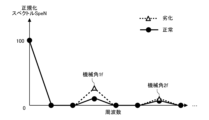
- FIG. 8 is a diagram showing an example of an image in which the degree of axial deterioration of the dynamic eccentricity estimation process in the dynamic eccentricity estimation unit 120 according to the first embodiment is expressed as a frequency characteristic.
- the horizontal axis represents frequency
- the vertical axis represents the normalized spectrum SpeN.
- the solid line in FIG. 8 represents the normalized spectrum SpeN of a normal compressor 5 in which no axial deterioration has occurred
- the dotted line represents the normalized spectrum SpeN of a compressor 5 in which axial deterioration has progressed.
- the mechanical angle component extraction unit 124 outputs the dynamic eccentricity West by focusing on the mechanical angle frequency. For example, by focusing on the mechanical angle 1f component of the mechanical angle frequency, the degree of dynamic eccentricity can be detected.
- the mechanical angle component extraction unit 124 outputs the dynamic eccentricity West by focusing on the mechanical angle 1f component, but this is not limited to this.
- the mechanical angle component extraction unit 124 may output the dynamic eccentricity West by focusing on other mechanical angle components, such as the mechanical angle 2f component.
- the dynamic eccentricity estimation unit 120 calculates the dynamic eccentricity West from the mechanical angular frequency. By estimating the degree of shaft deterioration using the dynamic eccentricity West, it is possible to improve the reliability of the compressor 5 and the refrigeration cycle device equipped with the compressor 5. This makes it possible to provide better service to users.
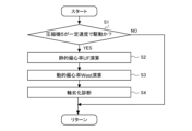
- the degradation diagnosis unit 100 repeats the degradation diagnosis process at regular intervals.
- the degradation diagnosis unit 100 determines whether the compressor 5 is driven at a constant speed (step S1). If the degradation diagnosis unit 100 determines that the compressor 5 is not driven at a constant speed, it repeats the process. Driving at a constant speed here means that the motor 53 is driven at the same rotation speed.
- the degradation diagnosis unit 100 calculates the current phase of the U-phase current Iu for each period, compares the phase for each period, and if there is almost no change, determines that the compressor 5 is driven at a constant speed.
- the degradation diagnosis unit 100 may determine whether the compressor 5 is driven at a constant speed based on the rotation speed estimated by the control device 10.
- the estimation accuracy of the static eccentricity UF and the dynamic eccentricity West is improved compared to when the compressor 5 is driven at an accelerated or decelerated speed. This improves the reliability of the system and allows the user to receive better service.
- the static eccentricity estimation unit 110 performs the static eccentricity estimation process as described above to calculate the static eccentricity ratio UF (step S2). Furthermore, the dynamic eccentricity estimation unit 120 performs the dynamic eccentricity estimation process as described above to calculate the dynamic eccentricity ratio West (step S3). Then, the shaft deterioration diagnosis unit 130 performs a diagnosis of shaft deterioration based on the static eccentricity ratio UF calculated by the static eccentricity estimation unit 110 and the dynamic eccentricity ratio West calculated by the dynamic eccentricity estimation unit 120 (step S4).
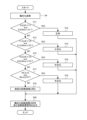
- FIG. 10 is a diagram explaining the flow of shaft deterioration determination processing performed by the shaft deterioration diagnosis unit 130 according to the first embodiment.
- the shaft deterioration diagnosis unit 130 determines whether the static eccentricity UF is greater than or equal to 0 and less than Y1, and the dynamic eccentricity West is greater than or equal to 0 and less than X1 (hereinafter referred to as condition 1) (step S11). If the shaft deterioration diagnosis unit 130 determines that condition 1 is met, it determines that the condition is "normal” (step S12). Then, it outputs a diagnosis result signal including a shaft deterioration diagnosis result SWR indicating that the condition is "normal” to the notification device 20 (step S20). The notification device 20 displays the normal state based on the diagnosis result signal.
- the shaft deterioration diagnosis unit 130 determines that condition 1 is not satisfied, it further determines whether the static eccentricity UF is greater than or equal to Y1 and less than Y2, and the dynamic eccentricity West is greater than or equal to X1 and less than X2 (hereinafter referred to as condition 2) (step S13). If the shaft deterioration diagnosis unit 130 determines that condition 2 is satisfied, it determines that there is "minor deterioration” (step S14). Then, it outputs a diagnosis result signal including a shaft deterioration diagnosis result SWR indicating "minor deterioration" to the notification device 20 (step S20). The notification device 20 displays the fact that there is minor deterioration based on the diagnosis result signal.
- the shaft deterioration diagnosis unit 130 determines that condition 2 is not satisfied, it further determines whether the static eccentricity UF is greater than or equal to Y2 and less than Y3, and the dynamic eccentricity West is greater than or equal to X2 and less than X3 (hereinafter referred to as condition 3) (step S15). If the shaft deterioration diagnosis unit 130 determines that condition 3 is satisfied, it determines that the condition is "moderately deteriorated" (step S16). Then, it outputs a diagnosis result signal including a shaft deterioration diagnosis result SWR indicating "moderately deteriorated" to the notification device 20 (step S20). The notification device 20 displays the effect of moderate deterioration based on the diagnosis result signal.
- condition 4 determines whether the static eccentricity UF is equal to or greater than Y3 and the dynamic eccentricity West is equal to or greater than X3 (hereinafter referred to as condition 4) (step S17). If the shaft deterioration diagnosis unit 130 determines that condition 4 is satisfied, it determines that the condition is "severely deteriorated" (step S18). Then, it outputs a diagnosis result signal including a shaft deterioration diagnosis result SWR indicating "severely deteriorated" to the notification device 20 (step S20). The notification device 20 displays the fact that the condition is "severely deteriorated” based on the diagnosis result signal.
- the shaft deterioration diagnosis unit 130 determines that condition 3 is not satisfied, it determines that the result is the same as the previous diagnosis (step S19). Then, it outputs a diagnosis result signal including the same shaft deterioration diagnosis result SWR as the previous one to the notification device 20 (step S20).
- the notification device 20 displays the same result as the previous diagnosis based on the diagnosis result signal.
- shaft deterioration diagnosis unit 130 compares the previous diagnosis result with the current diagnosis result and determines that the degree of shaft deterioration is worse in the current diagnosis result, it may output a diagnosis result signal based on the shaft deterioration diagnosis result SWR indicating the deterioration to the notification device 20.
- FIG. 11 is a diagram explaining the thresholds in the shaft deterioration determination process performed by the shaft deterioration diagnosis unit 130 according to the first embodiment.
- three thresholds (0 ⁇ Y1 ⁇ Y2 ⁇ Y3) are set for the static eccentricity UF.
- Three thresholds (0 ⁇ X1 ⁇ X2 ⁇ X3) are also set for the dynamic eccentricity West.
- the shaft deterioration diagnosis unit 130 determines the degree of shaft deterioration of the static eccentricity UF and the dynamic eccentricity West based on these thresholds, diagnoses shaft deterioration based on the determination, and outputs a diagnosis result signal based on the shaft deterioration diagnosis result SWR to the notification device 20.
- the number of thresholds for the static eccentricity UF and the dynamic eccentricity West do not have to be limited to three and the number of sections to four. Also, although this is not particularly limited, if the static eccentricity UF or the dynamic eccentricity West cannot be calculated and an estimated result for either cannot be obtained, a diagnosis result signal including the same shaft deterioration diagnosis result SWR as the previous time may be output to the notification device 20.
- the degradation diagnosis unit 100 of the control device 10 which serves as a degradation diagnosis device, calculates the static eccentricity UF and the dynamic eccentricity West based on the U-phase current Iu and the V-phase current Iv contained in the current detection signal Iuv.
- the degradation diagnosis unit 100 then performs shaft degradation diagnosis based on the static eccentricity UF and the dynamic eccentricity West, and outputs a diagnosis result signal including the shaft degradation diagnosis result SWR to the notification device 20.
- the degradation diagnosis unit 100 can improve the reliability of the equipment by diagnosing shaft degradation based on the two degrees of eccentricity, static eccentricity and dynamic eccentricity, caused by the main shaft 52. This makes it possible to provide better services to users.
- the degradation diagnosis unit 100 also has a static eccentricity estimation unit 110.
- the static eccentricity estimation unit 110 has a static eccentricity calculation unit 115 that calculates the ratio between the positive-sequence current I1 calculated by the positive-sequence current calculation unit 113 and the negative-sequence current I2 calculated by the negative-sequence current calculation unit 114 as a static eccentricity factor UF that indicates the degree of static eccentricity. This makes it possible to estimate the static eccentricity factor UF with higher accuracy.
- the degradation diagnosis unit 100 includes a dynamic eccentricity estimation unit 120 having an envelope calculation unit 121 that calculates an envelope Env for the phase current.
- the dynamic eccentricity estimation unit 120 further has a mechanical angle component extraction unit 124 that estimates and calculates the dynamic eccentricity factor West, which represents the degree of dynamic eccentricity, based on the mechanical angle component. Therefore, it is possible to estimate the dynamic eccentricity factor West with higher accuracy based on the mechanical angle obtained from the emphasized AC waveform.
- the deterioration diagnosis unit 100 determines that the compressor 5 is operating at a constant speed, and performs diagnosis processing based on the U-phase current Iu and V-phase current Iv contained in the current detection signal Iuv when the compressor is in a stable operating state. This allows for more accurate shaft deterioration diagnosis.
- Embodiment 2. 12 is a block diagram showing configurations of the deterioration diagnosis unit 100 and the deterioration estimation learning unit 200 in the control device 10 according to the second embodiment.
- the control device 10 in the second embodiment has a deterioration estimation learning unit 200 in addition to the deterioration diagnosis unit 100.
- the deterioration estimation learning unit 200 performs machine learning using the U-phase current Iu of the compressor 5, and creates a learned model for the dynamic eccentricity estimator 120 to obtain an estimation result. Therefore, in the second embodiment, the control device 10 serves as a deterioration estimation learning device and performs processing related to learning.
- the degradation estimation learning unit 200 has a learning unit 210 and a database storage unit 220.
- the learning unit 210 performs a learning process using machine learning to generate data related to the constructed trained model as a pattern generation function PGF.
- the database storage unit 220 then stores the pattern generation function PGF.
- the deterioration diagnosis unit 100 in the second embodiment differs in the configuration of the dynamic eccentricity estimation unit 120.
- the dynamic eccentricity estimation unit 120 in the second embodiment has an inference unit 125.
- the inference unit 125 in the second embodiment acquires the dynamic eccentricity ratio West using the pattern generation function PGF stored in the database storage unit 220.
- the dynamic eccentricity estimation unit 120 in the second embodiment uses the U-phase current Iu as input data and the dynamic eccentricity ratio West as output data.
- FIG. 13 is a diagram illustrating the flow of processing by the degradation estimation learning unit 200 according to the second embodiment.
- the processing procedure described below is an example of a learning method. Therefore, the order of each process performed by the degradation estimation learning unit 200 can be changed as much as possible. Furthermore, processes can be omitted, replaced, or added as appropriate depending on the content of the process.
- the deterioration estimation learning unit 200 acquires the U-phase current Iu of the compressor 5 as input data (step S21).
- the control device 10 acquires the U-phase current Iu when the motor 53 is driven in a state in which the main shaft 52 is in a deteriorated state. This makes it possible to acquire the U-phase current Iu relative to the deterioration amount of the main shaft 52.
- the input data is the U-phase current Iu, but the V-phase current Iv may also be used as the input data.
- the learning unit 210 also acquires the known amount of deterioration as a label (step S22).
- the known amount of deterioration refers to, for example, the amount of deterioration and wear that the main shaft 52 of the compressor 5 has undergone from a normal state (for example, 50 ⁇ m, 100 ⁇ m, or 150 ⁇ m, etc.).
- the learning unit 210 acquires a set of data (hereinafter referred to as a teacher data set) consisting of the input data acquired in step S21 and the label acquired in step S22 (step S23). Then, the learning unit 210 executes machine learning. The learning unit 210 executes machine learning based on the teacher data set to construct a trained model. This enables the learning unit 210 to link the relationship between the degree of deterioration in the dynamic eccentricity of the compressor 5 based on the deterioration amount and the phase current.
- a teacher data set a set of data consisting of the input data acquired in step S21 and the label acquired in step S22 (step S23). Then, the learning unit 210 executes machine learning. The learning unit 210 executes machine learning based on the teacher data set to construct a trained model. This enables the learning unit 210 to link the relationship between the degree of deterioration in the dynamic eccentricity of the compressor 5 based on the deterioration amount and the phase current.
- the machine learning performed by the learning unit 210 for the compressor 5 is learning with teacher data by a neural network configured by combining perceptrons.
- the learning unit 210 provides the neural network with a teacher data set consisting of input data indicating the state of the phase current and a label corresponding to the deterioration state of the compressor 5.
- the learning unit 210 then performs a process of repeating learning while changing the weighting value for each perceptron so that the output of the neural network is the same as the label.
- a process called back-propagation is repeated to adjust the weighting value so that the error in the output of each perceptron is reduced.
- the learning unit 210 performs a process of learning the characteristics of the teacher data set, and inductively acquires a trained model for estimating results from the input data. As a result, the learning unit 210 adjusts the weighting values by learning with teacher data, as described above, to eliminate errors between the labels and the output data.
- the learning unit 210 obtains, as a learning result, a trained model for determining the degree of dynamic eccentricity from the phase current through training with the teacher data.
- the learning unit 210 then saves and stores data relating to the trained model constructed by the learning unit 210 through training with the teacher data in the database storage unit 220 as a pattern generation function PGF (step S24).
- the pattern generation function PGF saved in the database storage unit 220 is used when the inference unit 125 executes the inference process, as described below.
- the learning unit 210 may update the pattern generation function PGF by periodically executing the processes from step S21 to step S24.
- the learning unit 210 may update the pattern generation function PGF by executing the processes from step S21 to step S24 every time the deterioration state of the compressor 5 changes.
- the learning unit 210 has saved the pattern generation function PGF using the U-phase current Iu as input data, but may generate the deterioration level based on data related to other currents.
- the learning unit 210 may build a learned model from at least one type of data based on data related to currents such as the likelihood, skewness, and harmonics of the current, and save it as the pattern generation function PGF.
- the learning unit 210 may have a multi-layered neural network and perform machine learning using so-called deep learning.
- FIG. 14 is a diagram showing the flow of processing in the inference unit 125 of the dynamic eccentricity estimation unit 120 according to the second embodiment.
- the inference unit 125 estimates the dynamic eccentricity West from the input U-phase current Iu.
- the inference unit 125 acquires the pattern generation function PGF stored in the database storage unit 220 (step S31).
- the inference unit 125 also acquires the U-phase current Iu sent from the current sensor 6 as input data (step S32).
- the inference unit 125 then inputs the data of the U-phase current Iu into the pattern generation function PGF, and calculates the dynamic eccentricity West of the main shaft 52 of the compressor 5.
- the control device 10 has a deterioration estimation learning unit 200.
- the deterioration estimation learning unit 200 stores a learned model obtained by the learning unit 210 performing machine learning based on the phase current in the database storage unit 220 as a pattern generation function PGF. Therefore, it is possible to estimate the dynamic eccentricity factor West based on the actual phase current. Then, the inference unit 125 of the dynamic eccentricity estimation unit 120 estimates the dynamic eccentricity factor West based on the phase current and the pattern generation function PGF. Therefore, it is possible to estimate and calculate the dynamic eccentricity factor West with higher accuracy. Therefore, it is possible to more accurately diagnose shaft deterioration, and improve the reliability of the equipment.
- Fig. 15 is a block diagram showing the configuration of shaft deterioration diagnosis unit 130 according to embodiment 3.
- the deterioration diagnosis unit 100 in embodiment 3 differs from embodiment 1 in the processing performed by shaft deterioration diagnosis unit 130.
- Fig. 15 shows the processing contents performed by shaft deterioration diagnosis unit 130 divided into each part.
- Shaft deterioration diagnosis unit 130 of embodiment 3 has static deterioration determination unit 131, dynamic deterioration determination unit 132, and comparison determination unit 133.
- the static deterioration determination unit 131 determines the static deterioration degree MUF based on the static eccentricity ratio UF calculated by the static eccentricity estimation unit 110. For example, the static deterioration determination unit 131 compares the static eccentricity ratio UF with preset thresholds Y1, Y2, and Y3, and determines the static deterioration degree MUF to be "normal,” “slight deterioration,” “medium deterioration,” or "severe deterioration.”
- the magnitude relationship of the thresholds for static eccentricity UF is set as 0 ⁇ Y1 ⁇ Y2 ⁇ Y3.
- the static deterioration determination unit 131 determines it as “normal”.
- the static deterioration determination unit 131 determines it as "slight deterioration”.
- the static deterioration determination unit 131 determines it as "medium deterioration”.
- the static deterioration determination unit 131 determines it as "severe deterioration”.
- the dynamic deterioration determination unit 132 determines the degree of dynamic deterioration MWest based on the dynamic eccentricity ratio West calculated by the dynamic eccentricity estimation unit 120. For example, the dynamic deterioration determination unit 132 compares the dynamic eccentricity ratio West with preset thresholds X1, X2, and X3, and determines the degree of dynamic deterioration MWest as either "normal,” “slight deterioration,” “medium deterioration,” or "severe deterioration.”
- the magnitude relationship of the threshold value for dynamic eccentricity West is set as 0 ⁇ X1 ⁇ X2 ⁇ X3.
- the dynamic deterioration determination unit 132 determines it as “normal.”
- the dynamic deterioration determination unit 132 determines it as "slightly deteriorated.”
- the dynamic deterioration determination unit 132 determines it as "moderately deteriorated.”
- the dynamic deterioration determination unit 132 determines it as "severely deteriorated.”
- the comparison and judgment unit 133 outputs the shaft deterioration diagnosis result SWR based on the static deterioration level MUF judged by the static deterioration judgment unit 131 and the dynamic deterioration level MWest judged by the dynamic deterioration judgment unit 132.
- the comparison and judgment unit 133 compares the static deterioration level MUF with the dynamic deterioration level MWest, and outputs the greater deterioration level as the shaft deterioration diagnosis result SWR.
- the deterioration levels obtained when the comparison and judgment unit 133 compares the static deterioration level MUF with the dynamic deterioration level MWest are the same, the deterioration level is output as the shaft deterioration diagnosis result SWR.
- the comparison and judgment unit 133 outputs "slightly deteriorated” as the shaft deterioration diagnosis result SWR.
- FIG. 16 is a diagram explaining the thresholds in the shaft deterioration judgment process performed by the shaft deterioration diagnosis unit 130 according to the third embodiment.
- three thresholds (0 ⁇ Y1 ⁇ Y2 ⁇ Y3) are set for the static eccentricity UF.
- Three thresholds (0 ⁇ X1 ⁇ X2 ⁇ X3) are also set for the dynamic eccentricity West.
- the comparison and judgment unit 133 judges the degree of shaft deterioration for each of the static eccentricity UF and the dynamic eccentricity West based on these thresholds.
- the comparison and judgment unit 133 then diagnoses the shaft deterioration based on the greater degree of shaft deterioration and outputs a diagnosis result signal based on the shaft deterioration diagnosis result SWR to the notification device 20.
- the thresholds are set at equal intervals, but this is not limited to this.
- thresholds may be set in advance at intervals other than equal intervals depending on the user's installation environment.
- three thresholds are set for each of the static eccentricity UF and the dynamic eccentricity West, and the static eccentricity UF and the dynamic eccentricity West are divided into four categories, and the shaft deterioration diagnosis result SWR is set to have four deterioration patterns, namely, "normal,” “slight deterioration,” “moderate deterioration,” and “severe deterioration.”
- this is not limited to this.
- two deterioration patterns, "normal” and "deterioration” may be used.
- the shaft deterioration diagnosis unit 130 may perform a diagnosis based on the eccentricity for which an estimated result was obtained, and a diagnosis result signal based on the shaft deterioration diagnosis result SWR may be output to the notification device 20.
- the comparison determination section 133 compares the static deterioration degree MUF determined by the static deterioration determination section 131 with the dynamic deterioration degree MWest determined by the dynamic deterioration determination section 132. Then, the shaft deterioration diagnosis section 130 determines the greater degree of deterioration between the static deterioration degree MUF and the dynamic deterioration degree MWest as the shaft deterioration diagnosis result SWR, and outputs a result signal to the notification device 20. Therefore, even if the degree of either the static eccentricity or the dynamic eccentricity is biased, it is possible to perform a highly accurate diagnosis of shaft deterioration and improve the reliability of the equipment. This makes it possible to provide better services to users.
- Embodiment 4. 17 is a block diagram illustrating a configuration example of a degradation diagnosis system SYS2 according to embodiment 4.
- the degradation diagnosis system SYS2 in embodiment 4 differs from the degradation diagnosis system SYS1 in embodiment 1 in the location where the degradation diagnosis unit 100 is installed.
- the degradation diagnosis unit 100 is included in the cloud server 30. Therefore, in embodiment 4, the cloud server 30 functions as a degradation diagnosis device.
- the cloud server 30 is, for example, a device that performs cloud storage processing in a cloud service.
- the cloud server 30 includes the degradation diagnosis unit 100 and a recording unit 310.
- the recording unit 310 has a non-volatile auxiliary storage device such as a flash memory capable of storing data for a long period of time as a recording device, and records data relating to the state quantities of the compressor 5.
- the data relating to the state quantities of the compressor 5 is data relating to the temperature, internal pressure, humidity, and refrigerant of the compressor 5, obtained based on signals from various sensors attached to the compressor 5.
- the data relating to the state quantities of the compressor 5 also includes data on the phase current supplied to the compressor 5.
- the data relating to the state quantities of the compressor 5 is included in a signal sent from the control device 10 via the electric communication line 40.
- the deterioration diagnosis unit 100 performs a shaft deterioration diagnosis process based on the data regarding the state quantities of the compressor 5 recorded by the recording unit 310, as described in the first to third embodiments, and outputs a signal including the shaft deterioration diagnosis result SWR to the notification device 20.
- the cloud server 30 has the deterioration diagnosis unit 100 which serves as a deterioration diagnosis device.
- a signal including data on the state quantity of the compressor 5 is sent to the cloud server 30 from the control device 10 which controls the compressor 5, which is the device to be diagnosed with deterioration, via the electrical communication line 40.
- the deterioration diagnosis unit 100 of the cloud server 30 then diagnoses shaft deterioration based on the phase current included in the sent signal, and outputs a signal including the shaft deterioration diagnosis result SWR to the notification device 20. This makes it possible to improve the reliability of the compressor 5 and the refrigeration cycle device equipped with the compressor 5. It is possible to diagnose shaft deterioration while taking into account the user's usage environment, and to provide better service to the user.
- the cloud server 30 has been described as having the degradation diagnosis unit 100, but this is not limited to this.
- the cloud server 30 may have the degradation estimation learning unit 200 described in the second embodiment. In this case, the cloud server 30 becomes the degradation estimation learning device.
- the cloud server 30 has been described here as having a degradation diagnosis unit 100 and a recording unit 310, this is not limited to this.
- the system may be configured with the degradation diagnosis device and the recording device as independent devices, connected so as to be able to communicate with each other via an electrical communication line 40.
- Embodiment 5 the compressor 5, which is a device having a rotating shaft, has been described as the device for which the deterioration diagnosis is performed, but the present invention is not limited to this.
- the present invention can be applied to any device having an electric motor 53 that rotates a rotating shaft by an electric current.
- the present invention can also be applied to a generator or the like.
Landscapes
- Physics & Mathematics (AREA)
- General Physics & Mathematics (AREA)
- Control Of Positive-Displacement Pumps (AREA)
Priority Applications (2)
| Application Number | Priority Date | Filing Date | Title |
|---|---|---|---|
| PCT/JP2023/020114 WO2024247114A1 (ja) | 2023-05-30 | 2023-05-30 | 劣化診断装置、劣化診断システム、劣化推定学習装置および劣化診断方法 |
| JP2025523749A JPWO2024247114A1 (https=) | 2023-05-30 | 2023-05-30 |
Applications Claiming Priority (1)
| Application Number | Priority Date | Filing Date | Title |
|---|---|---|---|
| PCT/JP2023/020114 WO2024247114A1 (ja) | 2023-05-30 | 2023-05-30 | 劣化診断装置、劣化診断システム、劣化推定学習装置および劣化診断方法 |
Publications (1)
| Publication Number | Publication Date |
|---|---|
| WO2024247114A1 true WO2024247114A1 (ja) | 2024-12-05 |
Family
ID=93657170
Family Applications (1)
| Application Number | Title | Priority Date | Filing Date |
|---|---|---|---|
| PCT/JP2023/020114 Ceased WO2024247114A1 (ja) | 2023-05-30 | 2023-05-30 | 劣化診断装置、劣化診断システム、劣化推定学習装置および劣化診断方法 |
Country Status (2)
| Country | Link |
|---|---|
| JP (1) | JPWO2024247114A1 (https=) |
| WO (1) | WO2024247114A1 (https=) |
Citations (6)
| Publication number | Priority date | Publication date | Assignee | Title |
|---|---|---|---|---|
| US20130033215A1 (en) * | 2011-08-01 | 2013-02-07 | Illinois Institute Of Technology | Apparatus and method for permanent magnet electric machine condition monitoring |
| US20160033580A1 (en) * | 2012-05-29 | 2016-02-04 | Board Of Regents Of The University Of Nebraska | Detecting Faults in Turbine Generators |
| WO2019167086A1 (en) * | 2018-03-01 | 2019-09-06 | Aurobinda Routray | A system for assessment of multiple faults in induction motors |
| WO2021166042A1 (ja) * | 2020-02-17 | 2021-08-26 | 三菱電機株式会社 | 永久磁石同期モータの診断装置およびこれを備えたインバータ |
| WO2022079796A1 (ja) * | 2020-10-13 | 2022-04-21 | 三菱電機株式会社 | 故障診断装置、学習装置、学習方法、および故障診断システム |
| CN115114848A (zh) * | 2022-06-13 | 2022-09-27 | 成都星云智联科技有限公司 | 一种基于混合cnn-lstm的三相异步电机故障诊断方法和系统 |
-
2023
- 2023-05-30 JP JP2025523749A patent/JPWO2024247114A1/ja active Pending
- 2023-05-30 WO PCT/JP2023/020114 patent/WO2024247114A1/ja not_active Ceased
Patent Citations (6)
| Publication number | Priority date | Publication date | Assignee | Title |
|---|---|---|---|---|
| US20130033215A1 (en) * | 2011-08-01 | 2013-02-07 | Illinois Institute Of Technology | Apparatus and method for permanent magnet electric machine condition monitoring |
| US20160033580A1 (en) * | 2012-05-29 | 2016-02-04 | Board Of Regents Of The University Of Nebraska | Detecting Faults in Turbine Generators |
| WO2019167086A1 (en) * | 2018-03-01 | 2019-09-06 | Aurobinda Routray | A system for assessment of multiple faults in induction motors |
| WO2021166042A1 (ja) * | 2020-02-17 | 2021-08-26 | 三菱電機株式会社 | 永久磁石同期モータの診断装置およびこれを備えたインバータ |
| WO2022079796A1 (ja) * | 2020-10-13 | 2022-04-21 | 三菱電機株式会社 | 故障診断装置、学習装置、学習方法、および故障診断システム |
| CN115114848A (zh) * | 2022-06-13 | 2022-09-27 | 成都星云智联科技有限公司 | 一种基于混合cnn-lstm的三相异步电机故障诊断方法和系统 |
Also Published As
| Publication number | Publication date |
|---|---|
| JPWO2024247114A1 (https=) | 2024-12-05 |
Similar Documents
| Publication | Publication Date | Title |
|---|---|---|
| CN111356910B (zh) | 一种实现旋转设备自动故障诊断及寿命预测的系统和方法 | |
| JP7378637B2 (ja) | 故障診断装置、学習装置、学習方法、および故障診断システム | |
| KR102208831B1 (ko) | 모터펌프의 진단 장치 및 방법 | |
| WO2008148075A1 (en) | Machine condition assessment through power distribution networks | |
| US20250216294A1 (en) | System, apparatus and method for misalignment-based remaining useful life estimation of a bearing | |
| CN116057364A (zh) | 异常判断装置、异常判断方法及程序 | |
| US20240344521A1 (en) | Method for Detecting a Fault, in Particular an Impeller Blockage, in a Centrifugal Pump, and Centrifugal Pump | |
| US20200125123A1 (en) | Hydraulic pump health monitoring | |
| US20250211147A1 (en) | Motor drive device, refrigeration cycle apparatus, and refrigeration cycle system | |
| CN111448752A (zh) | 电力转换装置及空气调节机 | |
| KR102034856B1 (ko) | 전동기 베어링 고장 및 상태 진단 방법 및 장치 | |
| WO2023089805A1 (ja) | 電動機制御装置、電動機制御システム、及び電動機の制御方法 | |
| WO2024247114A1 (ja) | 劣化診断装置、劣化診断システム、劣化推定学習装置および劣化診断方法 | |
| Fernandez-Temprano et al. | Broken bar condition monitoring of an induction motor under different supplies using a linear discriminant analysis | |
| WO2025088686A1 (ja) | 劣化診断装置、劣化診断システム、劣化推定学習装置および劣化診断方法 | |
| CN112487579B (zh) | 提升机构中运行组件的剩余寿命的预测方法及装置 | |
| TWI861830B (zh) | 異常診斷裝置、異常診斷系統、異常診斷方法以及程式 | |
| WO2024121931A1 (ja) | 集中管理システム、学習装置、および集中管理方法 | |
| JP7720920B2 (ja) | 電動機の診断装置、電動機の診断方法および電動機の異常予兆推論装置 | |
| JP2005214631A (ja) | 状態監視保全装置及び状態監視保全方法 | |
| JP6987280B2 (ja) | 診断システム及び冷凍サイクル装置 | |
| CN117501619A (zh) | 带电动机的设备的故障征兆检测装置以及带电动机的设备的故障征兆检测方法 | |
| WO2022190748A1 (ja) | 診断装置 | |
| US20260029489A1 (en) | System and method for monitoring motor winding degradation | |
| JP7814646B1 (ja) | 電動機負荷設備の診断装置 |
Legal Events
| Date | Code | Title | Description |
|---|---|---|---|
| 121 | Ep: the epo has been informed by wipo that ep was designated in this application |
Ref document number: 23939592 Country of ref document: EP Kind code of ref document: A1 |
|
| WWE | Wipo information: entry into national phase |
Ref document number: 2025523749 Country of ref document: JP |
|
| NENP | Non-entry into the national phase |
Ref country code: DE |