WO2024241901A1 - 情報処理装置、情報処理方法、及びプログラム - Google Patents
情報処理装置、情報処理方法、及びプログラム Download PDFInfo
- Publication number
- WO2024241901A1 WO2024241901A1 PCT/JP2024/017326 JP2024017326W WO2024241901A1 WO 2024241901 A1 WO2024241901 A1 WO 2024241901A1 JP 2024017326 W JP2024017326 W JP 2024017326W WO 2024241901 A1 WO2024241901 A1 WO 2024241901A1
- Authority
- WO
- WIPO (PCT)
- Prior art keywords
- crops
- images
- unit
- overlapping
- information processing
- Prior art date
- Legal status (The legal status is an assumption and is not a legal conclusion. Google has not performed a legal analysis and makes no representation as to the accuracy of the status listed.)
- Ceased
Links
Images






Classifications
-
- G—PHYSICS
- G06—COMPUTING OR CALCULATING; COUNTING
- G06Q—INFORMATION AND COMMUNICATION TECHNOLOGY [ICT] SPECIALLY ADAPTED FOR ADMINISTRATIVE, COMMERCIAL, FINANCIAL, MANAGERIAL OR SUPERVISORY PURPOSES; SYSTEMS OR METHODS SPECIALLY ADAPTED FOR ADMINISTRATIVE, COMMERCIAL, FINANCIAL, MANAGERIAL OR SUPERVISORY PURPOSES, NOT OTHERWISE PROVIDED FOR
- G06Q50/00—Information and communication technology [ICT] specially adapted for implementation of business processes of specific business sectors, e.g. utilities or tourism
- G06Q50/02—Agriculture; Fishing; Forestry; Mining
Definitions
- the present invention relates to an information processing device, an information processing method, and a program.
- Patent Document 1 discloses a system in which a work vehicle travels between multiple cultivation beds while an imaging device captures images of the fruits of the plants, processes the captured images to detect the fruits, and calculates the total number of fruits.
- the present invention aims to provide an information processing device, an information processing method, and a program that can accurately calculate the number of crops from multiple images of the crops.
- An information processing device includes an acquisition unit that acquires a plurality of images including one or more crops captured by one or more imaging devices in a specific region of a field, an identification unit that identifies overlapping regions between the respective regions of the plurality of images, a first calculation unit that calculates a first number of crops in the overlapping regions, a second calculation unit that calculates a second number of crops in non-overlapping regions other than the overlapping regions in the respective regions of the plurality of images, and a third calculation unit that calculates a third number of crops in the specific region based on the first number and the second number.
- a method includes a computer acquiring a plurality of images including one or more crops captured by one or more respective imaging devices in a specific area of a field, identifying overlapping areas between the respective areas of the plurality of images, calculating a first number of crops in the overlapping areas, calculating a second number of crops in non-overlapping areas other than the overlapping areas in the respective areas of the plurality of images, and calculating a third number of crops in the specific area based on the first and second numbers.
- a program causes a computer to execute an acquisition function for acquiring a plurality of images including one or more crops, the images being captured by one or more imaging devices in a specific area of a field; a determination function for identifying overlapping areas between the respective areas of the plurality of images; a first calculation function for calculating a first number of crops in the overlapping areas; a second calculation function for calculating a second number of crops in non-overlapping areas other than the overlapping areas in the respective areas of the plurality of images; and a third calculation function for calculating a third number of crops in the specific area based on the first and second numbers.
- the present invention provides an information processing device, information processing method, and program that can accurately calculate the number of crops from multiple images of the crops.
- FIG. 1 is a diagram showing an overview of a smart agriculture system according to an embodiment of the present invention.
- 2 is a conceptual diagram more specifically showing the field of view of a step surface S in the farm field shown in FIG. 1.
- 5A to 5C are schematic diagrams illustrating an example of an imaging method using the imaging device according to the present embodiment.
- 5A to 5C are schematic diagrams illustrating an example of a method for identifying overlapping areas in a plurality of images and a method for coordinate processing according to the present embodiment.
- 10A to 10C are schematic diagrams illustrating an example of a method for identifying overlapping regions in a plurality of images according to the embodiment.
- FIG. 2 is a diagram illustrating an example of a functional configuration of an information processing device according to the present embodiment.
- FIG. 1 is a diagram showing an overview of a smart agriculture system according to an embodiment of the present invention.
- 2 is a conceptual diagram more specifically showing the field of view of a step surface S in the farm field shown in FIG. 1.
- FIG. 2 is a diagram illustrating an example of the operation of the information processing device according to the embodiment.
- FIG. 2 is a diagram illustrating an example of a hardware configuration of an information processing device according to the present embodiment.
- FIG. 11 is a diagram illustrating an example of an image synthesis method according to the embodiment.
- the present embodiment an embodiment of the present invention (hereinafter referred to as "the present embodiment") will be described in detail with reference to the drawings as necessary, but the present invention is not limited to this, and various modifications are possible without departing from the gist of the invention.
- the same elements are given the same reference numerals, and duplicated explanations will be omitted.
- positional relationships such as up, down, left, and right will be based on the positional relationships shown in the drawings.
- the dimensional ratios of the drawings are not limited to those shown.
- FIG. 1 is a diagram showing an overview of a smart agriculture system 1 according to an embodiment of the present invention.
- the smart agriculture system 1 includes an information processing device 200 and a measurement device 300.
- the measurement device 300 may be, for example, various sensors such as a mobile sensor 310 and/or a fixed sensor 320.
- the information processing device 200 may be a terminal device 200a and/or a server device 200b.
- the information processing device 200 and the measurement device 300 may be connected via a network N.
- various sensors such as the fixed sensor 320 and the mobile sensor 310 are used to acquire images (hereinafter simply referred to as "images") of the crops in the field.
- the acquired images are then stored by the information processing device 200 (e.g., the server device 200b).
- the information processing device 200 e.g., the terminal device 200a
- the crops may also be, specifically, fruit flowers or berries.
- the crops may be fruit vegetables, such as tomatoes, eggplants, or peppers.
- the information processing device 200 may be a terminal device such as a laptop or a smartphone, or a server device such as a storage server.
- the information processing device 200 executes a predetermined program to connect to the measurement device 300 to transmit and receive various data, store various received data, output various data to a user, and accept instructions from the user to the measurement device 300, etc., by voice input, operation input, etc.
- the server device 200b may be a cloud server or an edge server.
- the edge server may be installed in the field or near the field and perform data processing and analysis. This makes it possible to disperse the processing load and reduce communication delays because data is processed on the edge server side instead of being sent to the cloud server.
- the server device 200b which is an edge server, may collect images of crops from the measuring device 300 and store the collected images in the server device 200b, which is a cloud server.
- the terminal device 200a may then obtain the stored images and calculate the number of crops.
- a terminal device 200a having the same functions as the edge server may be provided.
- the measuring device 300 measures the crops and the like in the field and the surrounding environment, generates data indicating the results of the measurement (hereinafter also referred to as “measurement data"), and transmits it to the information processing device 200 or the like.
- the measuring device 300 is not particularly limited, and may be, for example, a device equipped with various sensors installed at any position in the field, a drone equipped with various sensors and flying in the field, or an unmanned aerial vehicle capable of moving in the field (hereinafter also referred to as "mobile robot"), a smartphone equipped with various sensors, a handheld computing device, a wearable device, or other terminal operated by a person.
- the sensor is not particularly limited as long as it includes an image sensor, and may further include an environmental sensor.
- the image sensor is one aspect of an imaging device. There are no particular limitations on the type of image sensor, so long as it is a sensor capable of capturing still or moving images.
- the image sensor may be, for example, a fixed camera installed in a field, a camera on a terminal such as a wearable device, or a camera installed on a mobile measuring device 300.
- the image sensor may be configured, for example, to continuously generate frame-by-frame images and capture a time-series of images (e.g., moving images).
- the environmental sensor is a sensor for measuring environmental information in the field of the crops 520.
- the environmental sensor There are no particular limitations on the environmental sensor, but examples include a weather sensor, a soil sensor, and a gas sensor.
- the mobile sensor 310 may be, for example, a drone traveling in a field equipped with various sensors. This drone is one form of a moving body.
- the mounted sensor may be, for example, one or more image sensors for capturing images of agricultural crops, and/or a GPS receiving antenna for measuring position information (e.g., latitude and longitude).
- position information e.g., latitude and longitude.
- the number of image sensors according to this embodiment may be, for example, one, or three or more.
- the fixed sensor 320 may be, for example, a fixed camera.
- the network N is composed of a wireless network or a wired network.
- Examples of the network include a mobile phone network, a PHS (Personal Handy-phone System) network, a wireless LAN (Local Area Network, including communication conforming to IEEE802.11 (so-called WI/Fi (registered trademark))), 3G (3rd Generation), LTE (Long Term Evolution), 4G (4th Generation), 5G (5th Generation), WiMax (registered trademark), infrared communication, visible light communication, Bluetooth (registered trademark), a wired LAN, a telephone line, a power line communication network, and a network conforming to IEEE1394, etc.
- FIG. 2 is a conceptual diagram more specifically showing the field of view of the step surface S in the field shown in FIG. 1.
- FIG. 2 agricultural crops with fruit at the ends of tree branches are shown, and shelves 530 are installed below the branches to support the branches.
- the mobile sensor 310 may travel under the branches and shelves 530 while pointing the sensor substantially upward relative to the ground, to capture images of the agricultural crops.
- multiple imaging devices installed in a mobile sensor 310 capture images of crops grown in a specific area, and the number of crops in the specific area is calculated from the captured images.
- the specific area is an area of the field for which the number of crops is to be calculated, and may be, for example, one or more plots among multiple plots in the field, or an area per unit area.
- each of the multiple imaging devices captures images of crops grown in a specific area in this way, multiple images are captured, and a portion of each area of the multiple images is overlapped to avoid any missed images.
- the number of crops can then be calculated based on the overlapping areas (hereinafter also referred to as "overlapping areas”) and non-overlapping areas (hereinafter also referred to as "non-overlapping areas").
- FIG. 3 An example of the process of capturing images and identifying overlapping areas by the mobile sensor 310 will be described with reference to Figures 3 to 5.
- left image sensor hereinafter also referred to as "left image sensor”
- right image sensor hereinafter also referred to as "right image sensor”
- the left image sensor 311a and the right image sensor 311b are one aspect of a first imaging device and a second imaging device.
- the left image sensor 311a and the right image sensor 311b capture images of crops grown on a shelf 530, for example, with the imaging direction being upward with respect to the ground.
- the left image sensor 311a and the right image sensor 311b are also collectively referred to as "image sensor 311" when there is no particular need to distinguish between them.
- FIG. 3 is a schematic diagram showing the mobile sensor 310 traveling in a specific area of a field, as seen from above.
- the shelf 530 has posts arranged at intervals of width W (for example, 4 to 5 m).
- the mobile sensor 310 travels along the area between the rows L of posts, near the center line C of the travel path.
- the mobile sensor 310 is mounted with a left image sensor 311a and a right image sensor 311b arranged in the left and right directions so as to capture images of the left and right areas, respectively.
- the left and right directions refer to directions that are approximately perpendicular to the traveling direction of the mobile sensor 310 (the longitudinal direction in the area between the rows of posts).
- the left image sensor 311a and the right image sensor 311b may be set to have their respective image capturing ranges overlapped, for example, so that no agricultural products are missed from being captured.
- the mobile sensor 310 may be set to have their respective image capturing ranges overlapped, for example, when capturing images of two adjacent travel paths, so that no agricultural products are missed from being captured.
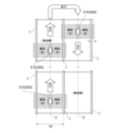
- 4A is a schematic diagram showing the overlap of the imaging ranges of the left image sensor 311a and the right image sensor 311b.
- an image P1 on the left side (hereinafter also referred to as the "left image") by the left image sensor 311a and an image P2 on the right side (hereinafter also referred to as the "right image") by the right image sensor 311b have an overlapping area of the same agricultural products, etc.
- the information processing device 200 acquires the left image P1 and the right image P2, and identifies an overlapping area A3 in each image as an overlapping area, and identifies non-overlapping areas A1 and A2 as non-overlapping areas.
- FIG. 4B is a schematic diagram showing an example of a method of coordinate processing of an image by the mobile sensor 310.
- the information processing device 200 may perform coordinate conversion so as to match one of the coordinate system S1 of the left image P1 and the coordinate system S2 of the right image P2 with the other coordinate system based on the relative positions of the left image sensor 311a and the right image sensor 311b.
- the information processing device 200 may convert the center coordinates of the crop in the coordinate system S1 detected in the left image P1 to the coordinate system S2.
- the information processing device 200 integrates the crops detected in each of the left image P1 and the right image P2 based on the center coordinates of the crop in the coordinate system S2.
- the information processing device 200 may identify a plurality of crops whose center coordinates are within a predetermined range, in other words, whose distance between center coordinates is within a threshold, as the same crop.
- FIG. 5A is a schematic diagram showing the overlap of the imaging range before and after the mobile sensor 310 turns around to the adjacent running path.
- the imaging range of the right image sensor on the running path A is from the center line C1 to the right end + ⁇ in the short direction of the running path A.
- the imaging range of the right image sensor on the running path B is from the center line C2 to the right end + ⁇ in the short direction of the running path B. Then, the right images captured on each of the running paths A and B may be overlapped by ⁇ (the part surrounded by the dashed ellipse).
- the information processing device 200 may perform, as a preprocessing step, for example, rotating the right image of the path B by 180 degrees to align it with the orientation of the right image of the path A.
- the marker object may be any object that serves as a reference point among those installed for cultivating agricultural crops, for example, a structure such as a cultivation shelf or part of a building such as an agricultural greenhouse (for example, the framework of the structure such as posts or joints), a signboard installed in the field, or a rope used for guiding crops.
- a structure such as a cultivation shelf or part of a building such as an agricultural greenhouse (for example, the framework of the structure such as posts or joints), a signboard installed in the field, or a rope used for guiding crops.
- Identifying overlapping areas in the running direction> 5B is a schematic diagram showing the overlap of the imaging range of time-series images due to the movement of the mobile sensor 310.
- the imaging range may overlap between adjacent images in the time-series images, for example, the left image P1 and the right image P2 at a specific time point and the left image P1' and the right image P2' t seconds before the specific time point (for example, the part surrounded by the dashed ellipse).
- the information processing device 200 may, for example, obtain position information associated with the measurement time of the mobile sensor 310, and calculate the amount of movement for t seconds based on this position information.
- the information processing device 200 may specify the overlapping area between the left image P1 and the right image P2 and the left image P1' and the right image P2' based on this amount of movement.
- the smart agriculture system 1 can calculate the number of crops in a specific area from the number of crops calculated in the overlapping and non-overlapping areas. This makes it possible to calculate the number of crops taking into account the overlap of multiple images. This makes it possible to avoid double counting even when multiple images are taken with overlapping shooting ranges so that no crops are missed. Therefore, the number of crops can be calculated with high accuracy from multiple images of the crops.
- the information processing device 200 includes a control unit 210, a communication unit 220, an input/output unit 230, and a storage unit 240.
- the control unit 210 includes an acquisition unit 211, an identification unit 212, and a calculation unit 216.
- the control unit 210 may also include a coordinate processing unit 213, a synthesis unit 214, and/or a detection unit 215, for example.
- the acquisition unit 211 acquires various data from the measurement device 300, the other information processing device 200, the storage unit 240, etc.
- the acquisition unit 211 may store the acquired various data in the storage unit 240.
- the acquisition unit 211 acquires a plurality of images including one or more agricultural crops captured by one or more image sensors 311 in a specific area of the farm field.
- the acquisition unit 211 receives data indicating an image including agricultural crops (hereinafter, also referred to as "image data”) from the image sensor 311 or the other information processing device 200 via the communication unit 220.
- the image data is one of the measurement data, and may include (or may be associated with) date and time information and/or position information when the image is captured, for example.
- the image data may include association of these images.
- the acquisition unit 211 may calculate the amount of movement of the mobile sensor 310 during a predetermined period, such as the image capture time, based on the acquired position information.
- the acquisition unit 211 may store information indicating this calculated amount of movement in the storage unit 240.
- the acquisition unit 211 may acquire, for example, an image including one or more agricultural crops, in which one or more image sensors 311 capture images of the agricultural crops along a predetermined direction (e.g., the traveling direction of the mobile sensor 310).
- a predetermined direction e.g., the traveling direction of the mobile sensor 310.
- the acquisition unit 211 may acquire the amount of movement of the image sensor from the image sensor 311 or the like (or by referring to the storage unit 240).
- the amount of movement of the image sensor 311 may be, for example, the amount of movement of the mobile sensor 310 on which the image sensor 311 is installed.
- the identification unit 212 identifies an overlapping area between the respective areas of the multiple images.
- the overlapping areas identified by the identification unit 212 may be, for example, (1) overlapping caused by multiple adjacent image sensors as described in the example of 2-2 above, (2) overlapping caused by turning around as described in the example of 2-4 above, and (3) overlapping in the traveling direction as described in the example of 2-5 above.
- a combination of the left image P1 and the right image P2 may be used as a target for identifying the overlapping area.
- the identification unit 212 may identify a combination of multiple images as a target for identifying the overlapping area based on, for example, position information and/or date and time information included in the image data.
- the identification unit 212 may, for example, calculate the similarity for each unit area of the left image P1 and the right image P2, and identify each unit area for which the calculated similarity exceeds a threshold as an overlapping area.
- the identification unit 212 may also calculate the similarity of the feature amounts related to the shape of each of the crops detected by the detection unit 215 and the similarity of the feature amounts related to the arrangement of each of the crops as the similarity for each unit area of the left image P1 and the right image P2.
- the identification unit 212 may calculate an overall similarity based on each of these calculated results. In this case, the identification unit 212 may perform the calculation by weighting the feature amounts related to the arrangement more heavily than the feature amounts related to the shape, so as to prioritize the arrangement over the shape of the crops.
- the identification unit 212 may identify, as the overlapping area, an area where an area of an image captured by the first image sensor (e.g., left image P1) overlaps with an area of an image captured by the second image sensor (e.g., right image P2). With this configuration, even if two or more image sensors 311 capture images with overlapping imaging ranges to avoid missing images, it is possible to avoid calculating the number of crops in duplicate.
- first image sensor e.g., left image sensor 311a
- a second image sensor e.g., right image sensor 311b
- the identification unit 212 may, for example, identify an overlapping area as an area formed by overlapping ends of multiple images captured in adjacent rows of multiple rows (e.g., paths A and B) running in a predetermined direction. With this configuration, when capturing images of crops along a predetermined direction, even if the images captured in adjacent rows of multiple rows formed in the predetermined direction overlap, the number of crops can be calculated taking this overlap into account.
- the identification unit 212 may, for example, identify overlapping areas between adjacent images in the time series (in other words, between frames) as overlapping areas. With this configuration, the number of crops can be calculated based on overlapping areas in time series images such as a video.
- the identification unit 212 may identify the overlapping area based on, for example, the amount of movement of the image sensor 311 acquired by the acquisition unit 211. With this configuration, even if the image sensor 311 is moving while capturing images of agricultural crops, it is possible to identify the overlapping area in time-series images, etc., based on this movement.
- the coordinate processing unit 213 aligns the coordinate system of the first image captured by the first image sensor with the coordinate system of the second image captured by the second image sensor based on the relative positions between the first image sensor and the second image sensor.
- the coordinate processing unit 213 may perform coordinate conversion to align the coordinate system of the first image or the coordinate system of the second image with the coordinate system of the other image, for example.
- the coordinate processing unit 213 includes an integration unit 213a.
- the integration unit 213a integrates the crops in the overlapping area based on the central coordinates of the crops included in the first image and the second image whose coordinate systems are aligned.
- the synthesis unit 214 synthesizes two or more images from among a plurality of images targeted for a specific region to generate a synthetic image.
- the synthesis unit 214 may, for example, synthesize a plurality of images based on an overlapping region identified by the identification unit 212 to generate a synthetic image. Specifically, the synthesis unit 214 may generate a synthetic image so that the overlapping portion becomes an overlapping portion when synthesizing the identified overlapping region. Note that when the synthesis process by the synthesis unit 214 and the coordinate conversion process by the coordinate processing unit 213 are performed in combination, for example, the synthesis process may be performed after the coordinate conversion process.
- the detection unit 215 detects one or more agricultural crops included in the image acquired by the acquisition unit 211 using image processing techniques such as machine learning, deep learning, or pattern recognition. During detection, the detection unit 215 may, for example, identify information such as the size, color, shape, or position in the image of each of the one or more agricultural crops (hereinafter, these are collectively referred to as "crop attribute information"). In addition, the detection unit 215 may, for example, assign identification information for identifying each of the one or more detected agricultural crops, and store this identification information, the crop attribute information, date and time information and/or position information included in the image data, and other measurement data in the storage unit 240 in association with each other.
- image processing techniques such as machine learning, deep learning, or pattern recognition.
- the detection unit 215 may, for example, identify information such as the size, color, shape, or position in the image of each of the one or more agricultural crops (hereinafter, these are collectively referred to as "crop attribute information").
- the detection unit 215 may, for example
- the detection unit 215 may detect the crops, for example, before the overlapping areas are identified by the identification unit 212, or after they are identified. In the latter case, the detection unit 215 may detect the crops, for example, for each overlapping area and/or each non-overlapping area.
- the detection unit 215 may, for example, when detecting agricultural crops, determine whether the detected agricultural crop is incomplete or not (or whether it is complete or not).
- An incomplete agricultural crop may, for example, be one in which the agricultural crop is not completely contained in the area of the image to be detected.
- the detection unit 215 may determine that an agricultural crop in which part is missing due to a boundary between multiple areas or an edge of an area is not completely contained in the area.
- the detection unit 215 may associate information indicating the result of the determination of whether the agricultural crop is incomplete or not with each of the one or more detected agricultural crops.
- the detection unit 215 may, for example, detect one or more agricultural crops in each image in the time series.
- the detection unit 215 may include, for example, a tracking unit 215a.
- the tracking unit 215a tracks each of the one or more detected crops between adjacent images in the time series.
- the tracking unit 215a may, for example, track each of one or more agricultural crops further based on the result of the interpolation performed by the interpolation unit 215b. With this configuration, even if the agricultural crop to be tracked is obscured by leaves or the like and cannot be detected, it is possible to continue tracking the crop by interpolation.
- the detection unit 215 may include, for example, an interpolation unit 215b.
- the interpolation unit 215b interpolates crops that have not been detected by the detection unit 215 between adjacent images in the time series based on the amount of movement of the image sensor 311. Specifically, the interpolation unit 215b may predict the position in the image of each of one or more crops t seconds later based on the amount of movement of the image sensor 311 in t seconds, and interpolate undetected crops based on the result of this prediction.
- the calculation unit 216 calculates the number of crops in the field. Furthermore, the calculation unit 216 may calculate a statistical value of the crops in the field as the calculation of the number of crops, for example, when there are multiple regions to be calculated. The statistical value may be, for example, the total number of crops, the average value, the median value, the maximum value, the minimum value, or the mode. The calculation unit 216 may store count information indicating the calculation result in the storage unit 240 in association with the measurement data.
- the calculation unit 216 includes a first calculation unit 216a.
- the first calculation unit 216a calculates the number of crops in the overlapping area identified by the identification unit 212 (hereinafter, also referred to as the "first number").
- the first calculation unit 216a may, for example, calculate the number of crops in each of the regions of the multiple images that correspond to the overlapping region, and use the number of crops in the region with the largest number as the first number based on the result of this calculation. Specifically, the first calculation unit 216a may use the maximum value from among the numbers of crops calculated in each of the regions of the multiple images that correspond to the overlapping region.
- the first calculation unit 216a may, for example, calculate, as the first number, the average value of the number of crops in each of the multiple images corresponding to the overlapping area. With this configuration, even if there is a difference in the number of crops calculated for each of the multiple images corresponding to the overlapping area, it can be averaged out.
- the first calculation unit 216a may, for example, calculate the first number of crops further based on the result of the integration by the integration unit 213a.
- the first calculation unit 216a may calculate the integrated crops, i.e., multiple crops identified as the same, as one crop. With this configuration, even if the imaging directions of the first image sensor and the second image sensor are not parallel to each other, the coordinate systems can be aligned to integrate the crops imaged by each sensor, and the number can be calculated based on the integrated crops, making it possible to accurately calculate the number of crops in the overlapping area.
- the first calculation unit 216a may calculate the first number of overlapping areas based, for example, on the results of tracking by the tracking unit 215a. With this configuration, the number of crops can be calculated with high accuracy even if areas overlap between adjacent images in the time series.
- the calculation unit 216 includes a second calculation unit 216b.
- the second calculation unit 216b calculates the number of crops in the non-overlapping areas other than the overlapping areas in each of the multiple images (hereinafter, also referred to as the "second number").
- the second calculation unit 216b may calculate the number of crops in the composite image as a second number of crops in the non-overlapping area. In other words, since the problem of double counting does not occur even in overlapping areas in a composite image made up of multiple images, the second calculation unit 216b calculates the number of crops by treating the area of the composite image as a non-overlapping area. With this configuration, the composite image can be appropriately used to accurately calculate the number of crops in a specific area.
- the second calculation unit 216b may, for example, calculate the second number of non-overlapping areas further based on the results of tracking. With this configuration, the number of crops can be calculated with high accuracy even if areas overlap between adjacent images in the time series.
- the first calculation unit 216a may calculate the first number based on, for example, the result of the determination by the detection unit 215 as to whether each of the one or more crops is incomplete. Specifically, the first calculation unit 216a may exclude crops determined to be incomplete from the calculation of the first number. In other words, the first calculation unit 216a may not count incomplete crops in the overlapping area. On the other hand, the second calculation unit 216b may include crops determined to be incomplete in the calculation of the second number. Note that the first calculation unit 216a and the second calculation unit 216b may be reversed, and the first calculation unit 216a may count incomplete crops. With this configuration, it is possible to avoid overlapping calculations in the overlapping area and the non-overlapping area for crops located across the overlapping area and the non-overlapping area.
- the calculation unit 216 includes a third calculation unit 216c.
- the third calculation unit 216c calculates the number of crops in the specific area (hereinafter also referred to as the "third number") based on the first number calculated by the first calculation unit 216a and the second number calculated by the second calculation unit 216b.
- the third calculation unit 216c can calculate the number of crops in a specific area from the number of crops calculated in each of the overlapping and non-overlapping areas. This makes it possible to calculate the number of crops taking into account overlaps between multiple images. Thus, the third calculation unit 216c can avoid double counting, even when multiple images are taken of crops that partially overlap to ensure no crops are missed. This makes it possible for the third calculation unit 216c to accurately calculate the number of crops in a specific area of a field.
- the third calculation unit 216c may, for example, sum the second number and the number obtained by dividing the first number by the number of images that make up the overlapping area, and calculate the third number based on the result of this sum. With this configuration, the third calculation unit 216c can calculate the number of crops in a specific area based on the number of overlapping images.
- the communication unit 220 transmits and receives various data such as measurement data to and from the measurement device 300 and/or other information processing devices 200 via the network N.
- the input/output unit 230 transmits and receives measurement data and the like to and from external devices such as a display device and an external storage device.
- the storage unit 240 stores the identification information, the attribute information, the count information, and/or the measurement data of the crop in association with each other.
- the storage unit 240 may store each piece of data using a database management system (DBMS), or may store each piece of information using a file system.
- DBMS database management system
- the storage unit 240 may provide a table for each piece of data and manage the data by associating the tables with each other.
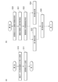
- FIG. 7(a) is a flow diagram showing the flow of the measurement data acquisition process in the information processing device 200.
- the acquisition unit 211 of the information processing device 200 acquires measurement data from the measurement device 300 or another information processing device 200 (step S10).
- the acquisition unit 211 stores this acquired measurement data in the storage unit 240 based on time (step S11).
- FIG. 7(b) is a flow diagram showing the flow of calculation processing for agricultural crops in the information processing device 200.
- the acquisition unit 211 of the information processing device 200 acquires from the memory unit 240 a plurality of images including one or more agricultural crops, which have been captured by each of the one or more image sensors 311 in a specific area of the field (step S20).
- the detection unit 215 detects each of the one or more agricultural crops from each of the acquired images (step S21).
- the identification unit 212 identifies overlapping areas between the respective areas of the multiple images and non-overlapping areas other than the overlapping areas in each of the multiple images (step S22). Note that the order of steps S21 and S22 may be reversed.
- the first calculation unit 216a of the information processing device 200 calculates a first number of crops in the overlapping area (step S23).
- the second calculation unit 216b calculates a second number of crops in the non-overlapping area in parallel with step S22 (step S24). Note that steps S23 and S24 may be processed in series, and if they are processed in series, the order does not matter.
- the third calculation unit 216c calculates a third number of crops in the specific area based on the first and second numbers (step S25).
- Hardware Configuration 8 an example of a hardware configuration in which the above-described information processing device 200 is realized by a computer 800 will be described. Note that the functions of each device can also be realized by dividing them into a plurality of devices.
- the computer 800 includes a processor 801, a memory 803, a storage device 805, an input I/F unit 807, a data I/F unit 809, a communication I/F unit 811, and a display device 813.
- the processor 801 controls various processes in the computer 800 by executing programs stored in the memory 803.
- each functional unit of the control unit 210 of the information processing device 200 can be realized by the processor 801 executing a program temporarily stored in the memory 803.
- Memory 803 is a storage medium such as a RAM (Random Access Memory). Memory 803 temporarily stores the program code of the program executed by processor 801, or data required when executing the program.
- RAM Random Access Memory
- the storage device 805 is a non-volatile storage medium such as a hard disk drive (HDD) or flash memory.
- the storage device 805 stores an operating system or various programs for implementing each of the above configurations.
- the storage device 805 can also store tables for registering measurement data, crop attribute information, etc., and a DB for managing the tables. Such programs or data are loaded into the memory 803 as necessary and are referenced by the processor 801.
- the input I/F unit 807 is a device for receiving input from a user. Specific examples of the input I/F unit 807 include a keyboard, a mouse, a touch panel, various sensors, and a wearable device. The input I/F unit 807 may be connected to the computer 800 via an interface such as a USB (Universal Serial Bus).
- USB Universal Serial Bus
- the data I/F unit 809 is a device for inputting data from outside the computer 800.
- a specific example of the data I/F unit 809 is a drive device for reading data stored in various storage media.
- the data I/F unit 809 may be provided outside the computer 800. In that case, the data I/F unit 809 is connected to the computer 800 via an interface such as a USB.
- the communication I/F unit 811 is a device for performing data communication via the Internet N, either wired or wirelessly, with devices external to the computer 800.
- the communication I/F unit 811 may be provided external to the computer 800. In that case, the communication I/F unit 811 is connected to the computer 800 via an interface such as a USB.
- the display device 813 is a device for displaying various types of information. Specific examples of the display device 813 include a liquid crystal display or an organic EL (Electro-Luminescence) display, a display of a wearable device, and the like.
- the display device 813 may be provided outside the computer 800. In that case, the display device 813 is connected to the computer 800 via, for example, a display cable.
- the display device 813 can be configured as an integral part of the input I/F unit 807.
- the image compositing unit 214 may composite images of agricultural crops based on a marker object shown in the image, rather than the overlapping area.
- the marker object may be any object that can serve as a reference among objects provided for cultivating agricultural crops, as described in the example of FIG. 5(a) above.
- FIG. 9 is a schematic diagram showing an example of an imaging method and image synthesis process using the mobile sensor 310.
- a left image P1 and a right image P2 from the left image sensor 311a and the right image sensor 311b, respectively may be synthesized to generate a synthetic image P3.
- images may be captured such that overlapping areas are provided between multiple images.
- the left image sensor 311a and the right image sensor 311b may set a marker object and capture images so that the marker object is included in the capture range (particularly the overlapping area).
- the information processing device 200 may then perform matching such as alignment based on the marker objects shown in the left image P1 and the right image P2, respectively, to generate a single composite image P3.
- the image synthesis process according to the present embodiment is not limited to this.
- the synthesis unit 214 may synthesize all of the target images based on the overlapping region or the marker object.
- the third calculation unit 216c may calculate the third number of crops in the specific region based on the synthesized image. With this configuration, the number of crops in the specific region can be calculated by using the marker object without identifying the overlapping region and without calculating the number of crops separately for the overlapping region and the non-overlapping region.
- each component of the information processing device 200 may be included in the measuring device 300.
- the function of detecting agricultural crops from an image included in the information processing device 200 i.e., the function realized by the detection unit 215, may be included in the measuring device 300.
- the information processing device 200 may acquire information indicating the result of this detection from the measuring device 300 and perform processing such as identifying overlapping areas and calculating the number of agricultural crops.
- a computer (200) An acquisition function (211) for acquiring a plurality of images including one or more crops captured by one or more image capture devices (311) in a specific area of a farm field; an identification function (212) for identifying overlap regions between respective regions of the plurality of images; a first calculation function (216a) for calculating a first number of crops in the overlap region; a second calculation function (216b) for calculating a second number of crops in non-overlapping areas other than the overlapping areas in each of the regions of the plurality of images; and a third calculation function (216c) for calculating a third number of crops in the particular area based on the first number and the second number. program.
Landscapes
- Business, Economics & Management (AREA)
- Engineering & Computer Science (AREA)
- Human Resources & Organizations (AREA)
- Marketing (AREA)
- Marine Sciences & Fisheries (AREA)
- Mining & Mineral Resources (AREA)
- Agronomy & Crop Science (AREA)
- Health & Medical Sciences (AREA)
- Economics (AREA)
- General Health & Medical Sciences (AREA)
- Life Sciences & Earth Sciences (AREA)
- Animal Husbandry (AREA)
- Primary Health Care (AREA)
- Strategic Management (AREA)
- Tourism & Hospitality (AREA)
- Physics & Mathematics (AREA)
- General Business, Economics & Management (AREA)
- General Physics & Mathematics (AREA)
- Theoretical Computer Science (AREA)
- Image Processing (AREA)
Priority Applications (3)
| Application Number | Priority Date | Filing Date | Title |
|---|---|---|---|
| AU2024276789A AU2024276789A1 (en) | 2023-05-19 | 2024-05-10 | Information processing device, information processing method, and program |
| JP2025522299A JPWO2024241901A1 (https=) | 2023-05-19 | 2024-05-10 | |
| EP24810909.2A EP4715721A1 (en) | 2023-05-19 | 2024-05-10 | Information processing device, information processing method, and program |
Applications Claiming Priority (2)
| Application Number | Priority Date | Filing Date | Title |
|---|---|---|---|
| JP2023-083234 | 2023-05-19 | ||
| JP2023083234 | 2023-05-19 |
Publications (1)
| Publication Number | Publication Date |
|---|---|
| WO2024241901A1 true WO2024241901A1 (ja) | 2024-11-28 |
Family
ID=93589126
Family Applications (1)
| Application Number | Title | Priority Date | Filing Date |
|---|---|---|---|
| PCT/JP2024/017326 Ceased WO2024241901A1 (ja) | 2023-05-19 | 2024-05-10 | 情報処理装置、情報処理方法、及びプログラム |
Country Status (4)
| Country | Link |
|---|---|
| EP (1) | EP4715721A1 (https=) |
| JP (1) | JPWO2024241901A1 (https=) |
| AU (1) | AU2024276789A1 (https=) |
| WO (1) | WO2024241901A1 (https=) |
Citations (6)
| Publication number | Priority date | Publication date | Assignee | Title |
|---|---|---|---|---|
| JP2013108927A (ja) * | 2011-11-24 | 2013-06-06 | Topcon Corp | 航空写真撮像方法及び航空写真撮像装置 |
| JP2016010374A (ja) * | 2014-06-30 | 2016-01-21 | 井関農機株式会社 | 養液供給装置 |
| JP2019017396A (ja) | 2018-11-12 | 2019-02-07 | 井関農機株式会社 | 果実の収穫システム |
| JP2019153109A (ja) * | 2018-03-05 | 2019-09-12 | ドローン・ジャパン株式会社 | 農業管理予測システム、農業管理予測方法、及びサーバ装置 |
| JP2021108586A (ja) * | 2020-01-10 | 2021-08-02 | 株式会社大林組 | 収穫予測装置、収穫予測方法 |
| JP2021189763A (ja) * | 2020-05-29 | 2021-12-13 | 国立研究開発法人農業・食品産業技術総合研究機構 | 推定装置、推定方法、及びプログラム |
-
2024
- 2024-05-10 JP JP2025522299A patent/JPWO2024241901A1/ja active Pending
- 2024-05-10 WO PCT/JP2024/017326 patent/WO2024241901A1/ja not_active Ceased
- 2024-05-10 AU AU2024276789A patent/AU2024276789A1/en active Pending
- 2024-05-10 EP EP24810909.2A patent/EP4715721A1/en active Pending
Patent Citations (6)
| Publication number | Priority date | Publication date | Assignee | Title |
|---|---|---|---|---|
| JP2013108927A (ja) * | 2011-11-24 | 2013-06-06 | Topcon Corp | 航空写真撮像方法及び航空写真撮像装置 |
| JP2016010374A (ja) * | 2014-06-30 | 2016-01-21 | 井関農機株式会社 | 養液供給装置 |
| JP2019153109A (ja) * | 2018-03-05 | 2019-09-12 | ドローン・ジャパン株式会社 | 農業管理予測システム、農業管理予測方法、及びサーバ装置 |
| JP2019017396A (ja) | 2018-11-12 | 2019-02-07 | 井関農機株式会社 | 果実の収穫システム |
| JP2021108586A (ja) * | 2020-01-10 | 2021-08-02 | 株式会社大林組 | 収穫予測装置、収穫予測方法 |
| JP2021189763A (ja) * | 2020-05-29 | 2021-12-13 | 国立研究開発法人農業・食品産業技術総合研究機構 | 推定装置、推定方法、及びプログラム |
Non-Patent Citations (1)
| Title |
|---|
| See also references of EP4715721A1 |
Also Published As
| Publication number | Publication date |
|---|---|
| JPWO2024241901A1 (https=) | 2024-11-28 |
| AU2024276789A1 (en) | 2025-10-30 |
| EP4715721A1 (en) | 2026-03-25 |
Similar Documents
| Publication | Publication Date | Title |
|---|---|---|
| Darwin et al. | Recognition of bloom/yield in crop images using deep learning models for smart agriculture: A review | |
| Rehman et al. | A revisit of internet of things technologies for monitoring and control strategies in smart agriculture | |
| Farjon et al. | Deep-learning-based counting methods, datasets, and applications in agriculture: A review | |
| Zhao et al. | Rapeseed seedling stand counting and seeding performance evaluation at two early growth stages based on unmanned aerial vehicle imagery | |
| US10698402B2 (en) | Agricultural robot | |
| Fonteijn et al. | Automatic phenotyping of tomatoes in production greenhouses using robotics and computer vision: From theory to practice | |
| Olenskyj et al. | End-to-end deep learning for directly estimating grape yield from ground-based imagery | |
| Halstead et al. | Crop agnostic monitoring driven by deep learning | |
| Fernández-Novales et al. | Monitoring and mapping vineyard water status using non-invasive technologies by a ground robot | |
| Jiang et al. | Tree trunk recognition in orchard autonomous operations under different light conditions using a thermal camera and faster R-CNN | |
| Ahmed et al. | Machine vision-based crop-load estimation using yolov8 | |
| Székely et al. | Bacterial-fungicidal vine disease detection with proximal aerial images | |
| Boudaa et al. | Advancing plant diseases detection with pre-trained yolo models | |
| Wang et al. | A review on the high-efficiency detection and precision positioning technology application of agricultural robots | |
| Yu et al. | Advancements in utilizing image-analysis technology for crop-yield estimation | |
| Pincheira et al. | Overcoming limitations of IoT installations: Active sensing UGV for agricultural digital twins | |
| Tseng et al. | Annual and in-season mapping of cropland at field scale with sparse labels | |
| Qi et al. | Assessment of the tomato cluster yield estimation algorithms via tracking-by-detection approaches | |
| Turečková et al. | Slicing aided large scale tomato fruit detection and counting in 360-degree video data from a greenhouse | |
| US20250190652A1 (en) | Estimation of effective pest-disease severity score using a personalized crop protocol driven unmanned scouting vehicle | |
| WO2024241901A1 (ja) | 情報処理装置、情報処理方法、及びプログラム | |
| Duman et al. | Design of a smart vertical farming system using image processing | |
| Shalash et al. | Fusion of Robotics, AI, and Thermal Imaging Technologies for Intelligent Precision Agriculture Systems | |
| Gao et al. | Individual plant detection and tracking for agricultural robotics in precision field management | |
| Jayanthi et al. | Transformative Impact of AI-Driven Computer Vision in Agriculture |
Legal Events
| Date | Code | Title | Description |
|---|---|---|---|
| 121 | Ep: the epo has been informed by wipo that ep was designated in this application |
Ref document number: 24810909 Country of ref document: EP Kind code of ref document: A1 |
|
| WWE | Wipo information: entry into national phase |
Ref document number: AU2024276789 Country of ref document: AU Ref document number: 826040 Country of ref document: NZ |
|
| ENP | Entry into the national phase |
Ref document number: 2025522299 Country of ref document: JP Kind code of ref document: A |
|
| WWE | Wipo information: entry into national phase |
Ref document number: 2025522299 Country of ref document: JP |
|
| ENP | Entry into the national phase |
Ref document number: 2024276789 Country of ref document: AU Date of ref document: 20240510 Kind code of ref document: A |
|
| WWE | Wipo information: entry into national phase |
Ref document number: 2024810909 Country of ref document: EP |
|
| NENP | Non-entry into the national phase |
Ref country code: DE |
|
| ENP | Entry into the national phase |
Ref document number: 2024810909 Country of ref document: EP Effective date: 20251219 |
|
| ENP | Entry into the national phase |
Ref document number: 2024810909 Country of ref document: EP Effective date: 20251219 |
|
| ENP | Entry into the national phase |
Ref document number: 2024810909 Country of ref document: EP Effective date: 20251219 |
|
| ENP | Entry into the national phase |
Ref document number: 2024810909 Country of ref document: EP Effective date: 20251219 |
|
| ENP | Entry into the national phase |
Ref document number: 2024810909 Country of ref document: EP Effective date: 20251219 |
|
| ENP | Entry into the national phase |
Ref document number: 2024810909 Country of ref document: EP Effective date: 20251219 |
|
| ENP | Entry into the national phase |
Ref document number: 2024810909 Country of ref document: EP Effective date: 20251219 |
|
| ENP | Entry into the national phase |
Ref document number: 2024810909 Country of ref document: EP Effective date: 20251219 |
|
| WWP | Wipo information: published in national office |
Ref document number: 2024810909 Country of ref document: EP |