WO2024241484A1 - エアロゾル生成システム - Google Patents
エアロゾル生成システム Download PDFInfo
- Publication number
- WO2024241484A1 WO2024241484A1 PCT/JP2023/019132 JP2023019132W WO2024241484A1 WO 2024241484 A1 WO2024241484 A1 WO 2024241484A1 JP 2023019132 W JP2023019132 W JP 2023019132W WO 2024241484 A1 WO2024241484 A1 WO 2024241484A1
- Authority
- WO
- WIPO (PCT)
- Prior art keywords
- opening
- opens
- closes
- battery
- housing
- Prior art date
- Legal status (The legal status is an assumption and is not a legal conclusion. Google has not performed a legal analysis and makes no representation as to the accuracy of the status listed.)
- Ceased
Links
Images

Classifications
-
- A—HUMAN NECESSITIES
- A24—TOBACCO; CIGARS; CIGARETTES; SIMULATED SMOKING DEVICES; SMOKERS' REQUISITES
- A24F—SMOKERS' REQUISITES; MATCH BOXES; SIMULATED SMOKING DEVICES
- A24F40/00—Electrically operated smoking devices; Component parts thereof; Manufacture thereof; Maintenance or testing thereof; Charging means specially adapted therefor
- A24F40/85—Maintenance, e.g. cleaning
-
- A—HUMAN NECESSITIES
- A24—TOBACCO; CIGARS; CIGARETTES; SIMULATED SMOKING DEVICES; SMOKERS' REQUISITES
- A24F—SMOKERS' REQUISITES; MATCH BOXES; SIMULATED SMOKING DEVICES
- A24F40/00—Electrically operated smoking devices; Component parts thereof; Manufacture thereof; Maintenance or testing thereof; Charging means specially adapted therefor
- A24F40/40—Constructional details, e.g. connection of cartridges and battery parts
-
- A—HUMAN NECESSITIES
- A24—TOBACCO; CIGARS; CIGARETTES; SIMULATED SMOKING DEVICES; SMOKERS' REQUISITES
- A24F—SMOKERS' REQUISITES; MATCH BOXES; SIMULATED SMOKING DEVICES
- A24F40/00—Electrically operated smoking devices; Component parts thereof; Manufacture thereof; Maintenance or testing thereof; Charging means specially adapted therefor
- A24F40/50—Control or monitoring
- A24F40/53—Monitoring, e.g. fault detection
-
- A—HUMAN NECESSITIES
- A24—TOBACCO; CIGARS; CIGARETTES; SIMULATED SMOKING DEVICES; SMOKERS' REQUISITES
- A24F—SMOKERS' REQUISITES; MATCH BOXES; SIMULATED SMOKING DEVICES
- A24F40/00—Electrically operated smoking devices; Component parts thereof; Manufacture thereof; Maintenance or testing thereof; Charging means specially adapted therefor
- A24F40/90—Arrangements or methods specially adapted for charging batteries thereof
-
- A—HUMAN NECESSITIES
- A24—TOBACCO; CIGARS; CIGARETTES; SIMULATED SMOKING DEVICES; SMOKERS' REQUISITES
- A24F—SMOKERS' REQUISITES; MATCH BOXES; SIMULATED SMOKING DEVICES
- A24F40/00—Electrically operated smoking devices; Component parts thereof; Manufacture thereof; Maintenance or testing thereof; Charging means specially adapted therefor
- A24F40/20—Devices using solid inhalable precursors
Definitions
- This disclosure relates to an aerosol generation system, a control method, and a program.
- an inhalation device generates an aerosol imparted with a flavor component using a base material containing an aerosol source for generating an aerosol and a flavor source for imparting a flavor component to the generated aerosol.
- a user can taste the flavor by inhaling the aerosol imparted with a flavor component generated by the inhalation device.
- the action of a user inhaling an aerosol is hereinafter also referred to as a puff or a puffing action.
- An example of a device classified as an inhalation device is a heated tobacco product that is used instead of a so-called paper cigarette.
- a heated tobacco product is a type of inhalation device that generates an aerosol by heating a solid that contains an aerosol source.
- Patent Document 1 discloses a suction device in which the battery can be replaced by removing a cover provided on the side of the suction device.
- Patent Document 1 the technology disclosed in the above-mentioned Patent Document 1 has only recently been developed, and there is still room for improvement in various respects.
- the present disclosure has been made in light of the above problems, and the purpose of the present disclosure is to provide a mechanism that can further improve the quality of the user experience.
- an aerosol generation system comprising: a housing; a substrate accommodating section having a first opening and accommodating a substrate so as to be insertable and removable through the first opening; a tubular member having a second opening and openings at both ends connected to the substrate accommodating section; a battery accommodating section having a third opening and accommodating a battery pack so as to be insertable and removable through the third opening; a load that generates energy for heating an aerosol source contained in the substrate accommodated in the substrate accommodating section by using power supplied from the battery pack accommodated in the battery accommodating section; and a control section that controls the operation of the load, wherein the first opening is provided on a surface of the housing in a first direction, and the second opening and the third opening are provided on a surface of the housing in a second direction opposite to the first direction.
- the aerosol generating system may further include a lid portion that opens and closes the second opening and a lid portion that opens and closes the third opening.
- the aerosol generation system may further include a locking mechanism that locks the lid that opens and closes the second opening in a state in which the second opening is closed, the locking mechanism having a recess and a claw portion, and locking the lid that opens and closes the second opening by inserting the claw portion into the recess, and unlocking the lid that opens and closes the second opening by removing the claw portion from the recess, and the claw portion may be provided on one of the lid that opens and closes the second opening and the housing, and the recess may be provided on the other.
- the aerosol generating system may further include a lid portion that opens and closes the third opening, and the lid portion that opens and closes the third opening may open and close the second opening as well as the third opening.
- the lid portion that opens and closes the third opening may be detachable from the housing.
- the aerosol generating system may further include a locking mechanism that locks the lid portion, which opens and closes the third opening, in a state in which the third opening is closed.
- the control unit may control the operation of the locking mechanism that locks the lid portion that opens and closes the third opening based on the operating state of the aerosol generation system.
- the aerosol generating system may further include a lid portion that opens and closes the first opening, and the control unit may control the operation of the locking mechanism that locks the lid portion that opens and closes the third opening so as to prohibit the release of the lock of the lid portion that opens and closes the third opening when the lid portion that opens and closes the first opening opens the first opening and the second opening is closed.
- the aerosol generating system may further include an opening/closing sensor that detects whether a lid that opens and closes the third opening is closing the third opening, and the control unit may control the operation of the load based on the detection result by the opening/closing sensor.
- the aerosol generating system may further include a liquid leakage detection unit that is arranged in a position in contact with the battery pack contained in the battery housing portion, and is made of a liquid-absorbent material and changes its appearance when it absorbs liquid.
- the aerosol generating system may further include a charging terminal that receives power supplied from an external power source to charge the battery pack, and the charging terminal may be disposed on the first direction side of the battery housing and offset from the load in the direction from the second opening toward the third opening.
- the aerosol generating system may further include the substrate.
- this disclosure provides a mechanism that can further improve the quality of the user experience.
- FIG. 2 is a schematic diagram showing a configuration example of a suction device.
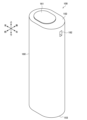
- 1 is a perspective view illustrating an example of an external configuration of a suction device according to an embodiment of the present disclosure.
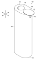
- FIG. 2 is a perspective view showing an example of an external configuration of the suction device according to the embodiment.
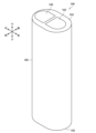
- FIG. 2 is a perspective view showing an example of an external configuration of the suction device according to the embodiment.
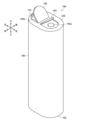
- FIG. 2 is a perspective view showing an example of an external configuration of the suction device according to the embodiment.
- 2 is a diagram illustrating an example of an internal configuration of a suction device according to the embodiment of the present invention.
- FIG. 2 is a diagram showing an internal configuration of a suction device according to the embodiment of the present invention.
- FIG. 13 is a diagram illustrating an example of a configuration near a cleaning hole cover on the bottom surface of a suction device according to a first modified example.
- FIG. 13 is a diagram illustrating an example of a configuration near a cleaning hole cover on the bottom surface of the suction device according to the modified example.
- FIG. 13 is a diagram illustrating an example of a configuration near a cleaning hole cover on the bottom surface of the suction device according to the modified example.
- FIG. 13 is a diagram illustrating an example of a configuration near a battery cover on the bottom surface of a suction device according to a second modified example.
- FIG. 13 is a diagram illustrating an example of a configuration near a battery cover on the bottom surface of the suction device according to the modified example.
- FIG. FIG. 13 is a diagram illustrating an example of an internal configuration of a suction device according to a third modified example.
- the inhalation device is a device that generates a substance to be inhaled by a user.
- the substance generated by the inhalation device is described as an aerosol.
- the substance generated by the inhalation device may be a gas.
- FIG. 1 is a schematic diagram showing an example of the configuration of a suction device.
- the suction device 100 includes a power supply unit 111, a sensor unit 112, a notification unit 113, a memory unit 114, a communication unit 115, a control unit 116, a heating unit 121, a storage unit 140, and a heat insulating unit 144.
- the power supply unit 111 stores power.
- the power supply unit 111 supplies power to each component of the suction device 100 under the control of the control unit 116.
- the power supply unit 111 may be configured, for example, by a rechargeable battery such as a lithium ion secondary battery.
- the sensor unit 112 acquires various information related to the suction device 100.
- the sensor unit 112 is configured with a pressure sensor such as a condenser microphone, a flow rate sensor, or a temperature sensor, and acquires values associated with suction by the user.
- the sensor unit 112 is configured with an input device such as a button or switch that accepts information input from the user.
- the notification unit 113 notifies the user of information.
- the notification unit 113 is composed of, for example, a light-emitting device that emits light, a display device that displays an image, a sound output device that outputs sound, or a vibration device that vibrates.
- the storage unit 114 stores various information for the operation of the suction device 100.
- the storage unit 114 is configured, for example, from a non-volatile storage medium such as a flash memory.
- the communication unit 115 is a communication interface capable of performing communication conforming to any wired or wireless communication standard.
- Such communication standards may include, for example, standards using Wi-Fi (registered trademark), Bluetooth (registered trademark), BLE (Bluetooth Low Energy (registered trademark)), NFC (Near Field Communication), or LPWA (Low Power Wide Area).
- the control unit 116 functions as an arithmetic processing unit and a control unit, and controls the overall operation of the suction device 100 in accordance with various programs.
- the control unit 116 is realized by an electronic circuit such as a CPU (Central Processing Unit) or a microprocessor.
- the storage section 140 has an internal space 141 and holds the stick-shaped substrate 150 while storing a part of the stick-shaped substrate 150 in the internal space 141.
- the storage section 140 has an opening 142 that connects the internal space 141 to the outside and stores the stick-shaped substrate 150 inserted into the internal space 141 through the opening 142.
- the storage section 140 is a cylindrical body with the opening 142 and the bottom 143 as the bottom surface, and defines a columnar internal space 141.
- An air flow path that supplies air to the internal space 141 is connected to the storage section 140.
- An air inlet hole which is an air inlet to the air flow path, is arranged, for example, on the side of the suction device 100.
- An air outlet hole which is an air outlet from the air flow path to the internal space 141, is arranged, for example, on the bottom 143.
- the stick-type substrate 150 includes a substrate portion 151 and a mouthpiece portion 152.
- the substrate portion 151 includes an aerosol source.
- the aerosol source includes a tobacco-derived or non-tobacco-derived flavor component.
- the aerosol source may include a medicine.
- the aerosol source may be, for example, a liquid such as a polyhydric alcohol such as glycerin and propylene glycol, and water, which includes a tobacco-derived or non-tobacco-derived flavor component, or may be a solid which includes a tobacco-derived or non-tobacco-derived flavor component.
- the stick-type substrate 150 When the stick-type substrate 150 is held in the storage portion 140, at least a portion of the substrate portion 151 is stored in the internal space 141, and at least a portion of the mouthpiece portion 152 protrudes from the opening 142.
- the suction mouth portion 152 protruding from the opening 142 in their mouth and inhales air flows into the internal space 141 via an air flow path (not shown) and reaches the user's mouth together with the aerosol generated from the base portion 151.
- the heating unit 121 generates aerosol by heating the aerosol source and atomizing the aerosol source.
- the heating unit 121 is configured in a film shape and is arranged to cover the outer periphery of the storage unit 140.
- the heating unit 121 generates heat, the substrate unit 151 of the stick-shaped substrate 150 is heated from the outer periphery, and an aerosol is generated.
- the heating unit 121 generates heat when power is supplied from the power supply unit 111.
- power may be supplied when the sensor unit 112 detects that the user has started inhaling and/or that specific information has been input. Power supply may be stopped when the sensor unit 112 detects that the user has stopped inhaling and/or that specific information has been input.
- the insulating section 144 prevents heat transfer from the heating section 121 to other components.
- the insulating section 144 is made of a vacuum insulating material, an aerogel insulating material, or the like.
- the configuration of the suction device 100 is not limited to the above, and various configurations such as those exemplified below are possible.
- the heating unit 121 may be configured in a blade shape and disposed so as to protrude from the bottom 143 of the storage unit 140 into the internal space 141.
- the blade-shaped heating unit 121 is inserted into the substrate 151 of the stick-shaped substrate 150 and heats the substrate 151 of the stick-shaped substrate 150 from the inside.
- the heating unit 121 may be disposed so as to cover the bottom 143 of the storage unit 140.
- the heating unit 121 may be configured as a combination of two or more of a first heating unit that covers the outer periphery of the storage unit 140, a blade-shaped second heating unit, and a third heating unit that covers the bottom 143 of the storage unit 140.
- the storage unit 140 may include an opening/closing mechanism such as a hinge that opens and closes a portion of the outer shell that forms the internal space 141. The storage unit 140 may then open and close the outer shell to accommodate the stick-shaped substrate 150 inserted into the internal space 141 while clamping it.
- the heating unit 121 may be provided at the clamping location in the storage unit 140, and may heat the stick-shaped substrate 150 while pressing it.
- the means for atomizing the aerosol source is not limited to heating by the heating unit 121.
- the means for atomizing the aerosol source may be induction heating.
- the suction device 100 has at least an electromagnetic induction source such as a coil that generates a magnetic field, instead of the heating unit 121.
- a susceptor that generates heat by induction heating may be provided in the suction device 100, or may be included in the stick-shaped substrate 150.
- FIGS 2 to 5 are perspective views showing an example of the external configuration of the suction device 100 according to this embodiment.
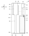
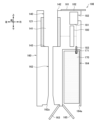
- Figures 6 and 7 are diagrams that generally show an example of the internal configuration of the suction device 100 according to this embodiment. Note that in Figures 2 to 7, illustration of components shown in Figure 1 may be omitted. In the following, duplicated descriptions of components described with reference to Figure 1 will be omitted.
- the suction device 100 may be configured as a straight cylinder with an oval-shaped top surface 102 and bottom surface 103.
- the suction device 100 is configured to a size that can be held by a user, and is used while being held by the user.
- the surface of the suction device 100 may be provided with a user interface, such as buttons for inputting operating instructions to the suction device 100 and a display that displays the operating status of the suction device 100.
- the direction in which the stick-shaped substrate 150 is inserted into and removed from the storage section 140 is also referred to as the up-down direction.
- the up-down direction corresponds to the longitudinal direction of the suction device 100.
- the longitudinal direction of the cross section of the suction device 100 is also referred to as the left-right direction, and the lateral direction is also referred to as the front-rear direction.
- the up-down direction is an example of the first direction.
- the down-down direction is an example of the second direction opposite the first direction.
- the suction device 100 has a housing 160 that constitutes the outermost shell of the suction device 100.
- the various components of the suction device 100 are disposed in the housing 160.
- the housing 160 is also provided with an opening 142, an opening 162a, and an opening 164a, which are opened and closed by a heater cover 161, a cleaning hole cover 163, or a battery cover 165. These components will be described in detail later.
- FIG. 2 illustrates a state in which the heater cover 161 closes the opening 142.
- FIG. 3 illustrates a state in which the heater cover 161 opens the opening 142.
- FIG. 4 illustrates a state in which the cleaning hole cover 163 closes the opening 162a, and the battery cover 165 closes the opening 164a.
- FIG. 5 illustrates a state in which the cleaning hole cover 163 opens the opening 162a, and the battery cover 165 opens the opening 164a.
- FIG. 6 shows a state in which the heater cover 161 closes the opening 142, the cleaning hole cover 163 closes the opening 162a, and the battery cover 165 closes the opening 164a.
- FIG. 7 shows a state in which the heater cover 161 opens the opening 142, the cleaning hole cover 163 opens the opening 162a, and the battery cover 165 opens the opening 164a.
- the suction device 100 has a storage section 140.
- the storage section 140 has an opening 142 equivalent to the first opening, and is an example of a substrate storage section that stores a stick-shaped substrate 150 so that it can be inserted and removed via the opening 142.
- the storage section 140 is a cylindrical body with an opening 142 on the upper side, and the stick-shaped substrate 150 is inserted downward and removed upward.
- the storage section 140 is also referred to as substrate storage section 140.
- the suction device 100 has a heater cover 161, which is a lid that opens and closes the opening 142 of the substrate storage section 140.
- the heater cover 161 may be configured as a slider that can slide left and right. By opening the heater cover 161, the user can expose the opening 142 and make it possible to insert the stick-shaped substrate 150. On the other hand, when the stick-shaped substrate 150 is not being inserted, the user can close the heater cover 161 to close the opening 142 and prevent debris such as debris that has fallen from the stick-shaped substrate 150 from falling through the opening 142.
- the suction device 100 has a cleaning hole 162.
- the cleaning hole 162 has an opening 162a corresponding to the second opening, and is a tubular member with openings at both ends that is connected to the substrate accommodating section 140.
- the cleaning hole 162 and the substrate accommodating section 140 are connected at the bottom 143 of the substrate accommodating section 140, forming a tube with openings at both ends, with the opening 142 and the opening 162a at both ends.
- a user can clean the substrate accommodating section 140 by inserting a cleaning tool such as a brush with a handle or a cotton swab from the opening 162a into the cleaning hole 162 and moving it so as to rub it against the inner wall of the substrate accommodating section 140.
- the cleaning hole 162 may be configured in a tapered shape with a diameter that widens in the downward direction near the opening 162a. This configuration makes it easier to insert a cleaning tool into the cleaning hole 162.
- the suction device 100 has a cleaning hole cover 163 that opens and closes the opening 162a of the cleaning hole 162.
- the cleaning hole cover 163 may open and close the opening 162a of the cleaning hole 162 using a hinge mechanism.
- the user can open the cleaning hole cover 163 to expose the opening 162a and make it possible to clean it.
- the user can close the cleaning hole cover 163 to close the opening 162a and prevent debris such as debris that has fallen from the stick-shaped base material 150 from falling through the opening 162a.
- the suction device 100 has a battery storage section 164.
- the battery storage section 164 has an opening 164a equivalent to the third opening, and stores the battery pack 170 so that it can be inserted and removed through the opening 164a.
- the battery storage section 164 is a cylindrical body having an opening 164a on the lower side, and the battery pack 170 is inserted upward and removed downward.
- the diameter of the opening 164a of the battery storage section 164 is configured to be larger than the diameter of the opening 162a of the cleaning hole 162. This is because the battery pack 170 is often larger than the cleaning tool.
- the battery accommodating section 164 may be configured in a shape that circumscribes the battery pack 170.
- the battery pack 170 be configured in a shape that is difficult to rotate around the vertical axis while accommodated in the battery accommodating section 164, such as an elliptical cylinder or a rectangular cylinder. With such a configuration, it is possible to limit the rotation of the battery pack 170 within the battery accommodating section 164, and easily maintain the connection between the battery terminal 183 and the electrode 171, which will be described later.
- the suction device 100 has a battery cover 165 that opens and closes the opening 164a.
- the battery cover 165 may open and close the opening 164a of the battery housing section 164 by a hinge mechanism.
- the user can open the battery cover 165 to expose the opening 164a and make the battery pack 170 replaceable.
- the battery pack 170 is not to be replaced, the user can close the battery cover 165 to conceal the battery pack 170, making it impossible to contact the battery pack 170, while preventing the battery pack 170 from falling off.
- the battery pack 170 is a rechargeable battery that is detachable from the suction device 100.
- the parts of the suction device 100 excluding the battery pack 170 are also referred to as the main body.
- the battery pack 170 supplies power for operation to various components of the main body of the suction device 100.
- the battery pack 170 has an electrode 171.
- the electrode 171 is a power interface between the battery pack 170 and the main body of the suction device 100.
- the battery pack 170 inputs or outputs power via the electrode 171.
- the battery pack 170 may have two electrodes, a positive electrode and a negative electrode, as the electrode 171.
- the suction device 100 has a battery terminal 183 arranged in the battery housing section 164.
- the battery terminal 183 is a power interface between the main body of the suction device 100 and the battery pack 170.
- the main body of the suction device 100 inputs or outputs power via the battery terminal 183.
- the battery terminal 183 is connected to the heating section 121, the control circuit 180, and the charging circuit 181 via wiring shown by dashed lines, and transmits and receives power between them.
- electrical connections with other components are omitted.
- the main body of the suction device 100 may have two terminals, a positive terminal and a negative terminal, as the battery terminal 183.
- the opening 142 of the substrate accommodating section 140 is provided on the top surface 102, which is the upper surface of the housing 160.
- the opening 162a of the cleaning hole 162 is provided on the bottom surface 103, which is the lower surface of the housing 160, at a position that overlaps with the opening 142 of the substrate accommodating section 140 in the front-rear and left-right directions.
- the opening 164a of the battery accommodating section 164 is provided on the same surface as the opening 162a of the cleaning hole 162, that is, the bottom surface 103, which is the lower surface of the housing 160.
- the mechanical structure of the suction device 100 can be simplified, making it possible to make the suction device 100 more compact.
- maintenance such as cleaning or replacing the battery pack 170 can be performed by simply operating the bottom surface 103 of the suction device 100, it is possible to standardize the maintenance method and improve usability.
- the suction device 100 has a control circuit 180.
- the control circuit 180 corresponds to the control unit 116 shown in Fig. 1.
- the control circuit 180 controls the overall processing within the suction device 100.
- the control circuit 180 controls the operation of the heating unit 121.
- the control of the operation of the heating unit 121 is realized by controlling the power supply from the battery pack 170 to the heating unit 121.
- the control circuit 180 can control the power supply from the battery pack 170 to the heating unit 121 based on the heating profile.
- the heating profile is control information for controlling the temperature at which the aerosol source is heated, and is, for example, information indicating the time series transition of the target value of the parameter corresponding to the temperature of the heating unit 121.
- the control circuit 180 controls the power supply to the heating unit 121 so that the parameter corresponding to the temperature of the heating unit 121 transitions as specified in the heating profile.
- the heating profile is typically designed to optimize the flavor tasted by the user when the user inhales the aerosol generated from the stick-shaped substrate 150. Therefore, the flavor tasted by the user can be optimized by controlling the operation of the heating unit 121 based on the heating profile.
- the parameter corresponding to the temperature of the heating section 121 may be the electrical resistance value of the heating section 121.
- the temperature of the heating section 121 can be measured, for example, based on the electrical resistance value of the heating section 121 (more precisely, the heating resistor that constitutes the heating section 121). This is because the electrical resistance value of the heating resistor changes depending on the temperature.
- the electrical resistance value of the heating resistor can be estimated, for example, by measuring the amount of voltage drop in the heating resistor.
- Another example of the parameter corresponding to the temperature of the heating section 121 may be the temperature of the heating section 121 itself.
- the temperature of the heating section 121 may be measured based on the electrical resistance value of the heating section 121, or may be measured by a temperature sensor such as a thermistor installed near the heating section 121.
- the temperature control of the heating section 121 can be achieved, for example, by known feedback control.
- the feedback control may be, for example, PID control (Proportional-Integral-Differential Controller).
- the control section 116 can supply power from the battery pack 170 to the heating section 121 in the form of pulses using pulse width modulation (PWM) or pulse frequency modulation (PFM). In this case, the control section 116 can control the temperature of the heating section 121 by adjusting the duty ratio of the power pulse in the feedback control.
- PWM pulse width modulation
- PFM pulse frequency modulation
- the suction device 100 has a charging circuit 181.
- the charging circuit 181 corresponds to the control unit 116 shown in Fig. 1.
- the charging circuit 181 controls the charging of the battery pack 170 based on the control by the control circuit 180.
- the charging circuit 181 supplies power supplied from an external power source via a charging terminal 182 to the battery pack 170. At that time, the charging circuit 181 can control the voltage and current of the power supplied to the battery pack 170.
- the suction device 100 has a charging terminal 182.
- the charging terminal 182 is an interface between the charging circuit 181 and an external power source that supplies power for charging the battery pack 170 housed in the battery housing section 164.
- the charging terminal 182 receives power for charging the battery pack 170 that is supplied from the external power source.
- the charging terminal 182 may be a USB (Universal Serial Bus) port.
- a USB cable may be connected to the charging terminal 182, and power may be supplied from an outlet via the USB cable.
- the charging terminal 182 is disposed on the upper side of the right side surface of the suction device 100.
- the charging terminal 182 is preferably disposed above the battery housing section 164 and in a position offset from the heating section 121 to the right, which is the direction from the opening 162a of the cleaning hole 162 toward the opening 164a of the battery housing section 164.
- the offset position here refers to a position that is separated or does not overlap.
- the charging terminal 182 may be disposed on the top surface 102 of the suction device 100, or on the front or rear surface of the suction device 100, in addition to the positions shown in FIGS. 6 and 7.
- this configuration makes it possible to shorten the wiring distance from the charging terminal 182 to the battery pack 170, thereby reducing power loss in the wiring and improving the charging efficiency of the battery pack 170.
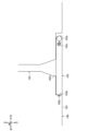
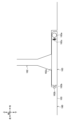
- FIGs 8 to 10 are diagrams that show an example of the configuration of the cleaning hole cover 163 and its vicinity on the bottom surface 103 of the suction device 100 according to the first modification.
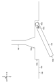
- Figure 8 shows a state in which the cleaning hole cover 163 is engaged with the housing 160 while closing the opening 162a of the cleaning hole 162.
- Figure 9 shows a state in which the cleaning hole cover 163 is disengaged from the housing 160 while closing the opening 162a of the cleaning hole 162.
- Figure 10 shows a state in which the cleaning hole cover 163 opens the opening 162a of the cleaning hole 162.
- the cleaning hole cover 163 has a rotation shaft 163a rotatably attached to the right side of the edge of the opening 162a of the cleaning hole 162 inside the right end of the cleaning hole cover 163. Therefore, the cleaning hole cover 163 can rotate around the rotation shaft 163a.
- the rotation shaft 163a is part of the hinge mechanism that opens and closes the cleaning hole cover 163.
- a convex claw portion 163b is provided on the end of the cleaning hole cover 163 farther from the rotation shaft 163a, i.e., the left end.
- a recess 162b into which the claw portion 163b can be inserted is provided near the opening 162a of the cleaning hole 162 of the housing 160 at a position corresponding to the claw portion 163b of the cleaning hole cover 163.
- the cleaning hole cover 163 and the rotating shaft 163a are connected via a spring 163c.
- the spring 163c is arranged so that it expands and contracts in the direction in which the distance between the claw portion 163b and the rotating shaft 163a increases and decreases.
- the expansion and contraction of the spring 163c enables the insertion of the claw portion 163b into the recess 162b shown in Figure 8, and the removal of the claw portion 163b from the recess 162b shown in Figure 9.
- the cleaning hole cover 163 closes the opening 162a of the cleaning hole 162
- the claw portion 163b is inserted into the recess 162b.
- the elastic force of the spring 163c acting in the direction of extension maintains the state in which the claw portion 163b is inserted into the recess 162b.
- the cleaning hole cover 163 can be locked in a state in which the opening 162a of the cleaning hole 162 is closed and engaged with the housing 160.
- FIG. 9 by applying a force to the cleaning hole cover 163 in the direction of contracting the spring 163c, the claw portion 163b can be removed from the recess 162b to release the lock of the cleaning hole cover 163.
- the cleaning hole 162 can be made rotatable.
- the suction device 100 may have a locking mechanism that locks the cleaning hole cover 163, which opens and closes the opening 162a of the cleaning hole 162, with the opening 162a closed.
- the rotating shaft 163a, claw portion 163b, spring 163c, and recess 162b shown in Figures 8 to 10 are one example of the locking mechanism.
- the locking mechanism is not limited to the example shown in Figures 8 to 10.
- the housing 160 may have a claw portion 163b instead of the recess 162b
- the cleaning hole cover 163 may have a recess 162b instead of the claw portion 163b.
- the suction device 100 may also have a locking mechanism for the heater cover 161 and/or a locking mechanism for the battery cover 165 in addition to or instead of the locking mechanism for the cleaning hole cover 163. That is, the suction device 100 may have a locking mechanism that locks the heater cover 161 when the opening 142 of the substrate housing section 140 is closed. The suction device 100 may also have a locking mechanism that locks the battery cover 165 when the opening 164a of the battery housing section 164 is closed.
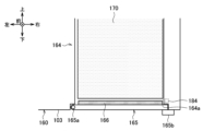
- FIGs 11 and 12 are diagrams that show an example of the configuration of the battery cover 165 and its vicinity on the bottom surface 103 of the suction device 100 according to the second modification.
- Figure 11 shows a state in which the battery cover 165 is engaged with the housing 160 while closing the opening 164a of the battery accommodating section 164.
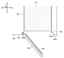
- Figure 12 shows a state in which the battery cover 165 opens the opening 164a of the battery accommodating section 164.
- the battery cover 165 has a rotation shaft 165a rotatably attached to the left side of the edge of the opening 164a of the battery housing section 164 on the inside of the left end of the battery cover 165. Therefore, the battery cover 165 can rotate around the rotation shaft 165a.
- the rotation shaft 165a is part of a hinge mechanism that opens and closes the battery cover 165.
- the suction device 100 has a fastener 165b that can slide left and right on the right side of the edge of the opening 164a of the battery housing section 164. As shown in FIG.
- the fastener 165b can lock the battery cover 165 in a state where it is engaged with the housing 160 by moving it to the left with the battery cover 165 closing the opening 164a of the battery housing section 164.
- the fastener 165b can move it to the right to unlock the battery cover 165 and make the battery cover 165 rotatable.
- the fastener 165b is an example of a locking mechanism that locks the opening 164a of the battery storage section 164 in a closed state.
- the locking mechanism is not limited to the example shown in Figures 11 and 12.
- the fastener 165b may be configured to be rotatable, and may lock or unlock the battery cover 165 depending on the rotation angle.
- the locking mechanism of the battery cover 165 may be configured in the same way as the locking mechanism of the cleaning hole cover 163 shown in the first modified example.
- the control circuit 180 may control the operation of the fastener 165b based on the operating state of the suction device 100. As an example, the control circuit 180 may prohibit the release of the lock by the fastener 165b while heating is being performed by the heating unit 121 or while the battery pack 170 is being charged. On the other hand, the control circuit 180 may permit the release of the lock by the fastener 165b only during a period when neither heating by the heating unit 121 nor charging of the battery pack 170 is being performed. Prohibition and permission of the release of the lock by the fastener 165b is achieved by fixing or making movable the fastener 165b. During heating by the heating unit 121 and charging of the battery pack 170, the battery pack 170 may become hot.
- control circuit 180 may control the operation of the fastener 165b based on instructions from a user terminal such as a smartphone that is wirelessly connected to the suction device 100 via Bluetooth or the like.
- the suction device 100 has an opening/closing sensor 184.
- the opening/closing sensor 184 detects whether the opening 164a of the battery housing section 164 is opened or closed by the battery cover 165.
- the opening/closing sensor 184 may be configured as a magnetic detection type proximity sensor such as a Hall sensor, and may detect whether the battery cover 165 is opened or closed based on whether or not a magnetism corresponding to the battery cover 165 is detected.
- the opening/closing sensor 184 may detect whether the battery cover 165 is opened or closed based on whether or not electricity is flowing, or whether or not light is detected.
- the suction device 100 may also be provided with a physical button that is pressed when the battery cover 165 is closed, and whether or not the battery cover 165 is opened or closed may be detected based on the pressed state of the physical button.
- the control circuit 180 may control the operation of the heating unit 121 based on the detection result by the open/close sensor 184. For example, the control circuit 180 may permit heating by the heating unit 121 only when the battery cover 165 is closed. This configuration can prevent the user from directly touching the battery pack 170 that has been heated by the heating unit 121, thereby improving safety.
- the charging circuit 181 may control charging of the battery pack 170 based on the detection result by the open/close sensor 184. For example, the charging circuit 181 may permit charging of the battery pack 170 only when the battery cover 165 is closed. This configuration can prevent the user from directly touching the battery pack 170 that has become warm during charging, thereby improving safety.
- the suction device 100 has a liquid leakage detection unit 166.
- the liquid leakage detection unit 166 is a member made of a liquid-absorbent material and changes its appearance when it absorbs liquid.
- the liquid-absorbent material may be paper, cloth, nonwoven fabric, a porous resin sheet, a coating film, or a combination of these.
- the change in appearance may be a change in color, a change in shape, expansion, or unevenness, or a combination of these.
- the liquid leakage detection unit 166 may be formed by printing a liquid-absorbing and soluble ink in a predetermined printing pattern on a liquid-absorbing sheet made of a highly absorbent material such as a water-absorbing polymer.
- the liquid-absorbing and soluble ink is an ink that can be printed in the same way as normal ink, and dissolves when it absorbs liquid after printing, causing a change in color, bleeding, deformation of the outer shape, or penetration and diffusion into the liquid-absorbing sheet.
- the liquid leakage detection unit 166 is arranged in a position that contacts the battery pack 170 contained in the battery container 164. Specifically, as shown in FIG. 11 and FIG. 12, the liquid leakage detection unit 166 may be disposed on the back side of the battery cover 165. In that case, the user can easily visually check the liquid leakage detection unit 166 by opening the battery cover 165. As another example, the liquid leakage detection unit 166 may be disposed on the inner wall of the battery housing portion 164.
- the liquid leakage detection unit 166 may be disposed on the surface of the battery pack 170. With this configuration, even if electrolyte leaks from the battery pack 170 due to factors such as aging, it is possible to absorb the electrolyte by the liquid leakage detection unit 166 and prevent leakage to the outside of the suction device 100. Furthermore, due to the change in the appearance of the liquid leakage detection unit 166, the user can easily visually check whether or not there is leakage from the battery pack 170, and safely replace the battery pack 170.
- an opening/closing sensor 184 is provided to detect whether the battery cover 165 is opened or closed, but the present disclosure is not limited to such an example.
- an opening/closing sensor that detects whether the heater cover 161 and/or the cleaning hole cover 163 is opened or closed may be provided.
- the control circuit 180 may permit or prohibit the unlocking of other locks based on the open/closed state of the heater cover 161, cleaning hole cover 163, and battery cover 165.
- the control circuit 180 may control the operation of the fastener 165b to prohibit the unlocking of the battery cover 165. More simply, when the heater cover 161 is open and the cleaning hole cover 163 is closed, the control circuit 180 may fix the fastener 165b in a state in which the battery cover 165 is locked. When the heater cover 161 is open and the cleaning hole cover 163 is closed, the stick-shaped substrate 150 may be inserted into the substrate housing section 140 and heating may be performed by the heating section 121. In this regard, according to this configuration, it is possible to prevent the user from directly touching the battery pack 170 that has been heated by the heating section 121, thereby improving safety.
- control circuit 180 may control the operation of the fastener 165b to allow the battery cover 165 to be unlocked when the heater cover 161 opens the opening 142 of the base material accommodating section 140 and the cleaning hole cover 163 opens the opening 162a of the cleaning hole 162. More simply, the control circuit 180 may allow the fastener 165b to be movable to unlock the battery cover 165 when both the heater cover 161 and the cleaning hole cover 163 are open. When both the heater cover 161 and the cleaning hole cover 163 are open, cleaning can be performed using a cleaning tool. In this regard, with such a configuration, cleaning and replacement of the battery pack 170 can be performed simultaneously, which improves maintainability.
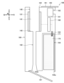
- FIG. 13 is a diagram showing an example of the internal configuration of the suction device 100 according to the third modification.
- the suction device 100 may have a bottom cover 167 for opening and closing the opening 162a of the cleaning hole 162 and the opening 164a of the battery housing section 164, instead of the cleaning hole cover 163 and the battery cover 165.
- the bottom cover 167 opens and closes the opening 164a of the battery housing section 164, and also opens and closes the opening 162a of the cleaning hole 162. Therefore, the user can open and close the opening 162a of the cleaning hole 162 and the opening 164a of the battery housing section 164 together by opening and closing the bottom cover 167. According to this configuration, it is possible to improve usability compared to the case where the cleaning hole cover 163 and the battery cover 165 are configured separately as in the above embodiment.
- the suction device 100 may further include a locking mechanism for locking the bottom cover 167.
- the suction device 100 may further include an opening/closing sensor for detecting whether the bottom cover 167 is opened or closed. Control of components such as the heating unit 121 based on the opening or closing of the bottom cover 167, and permission and prohibition of unlocking the bottom cover 167 may be performed in the same manner as in the modified example described above.
- the bottom cover 167 may be capable of selectively opening only one of the opening 162a of the cleaning hole 162 and the opening 164a of the battery housing 164.
- the bottom cover 167 may be configured as a slider that can slide left and right on the bottom surface 103 of the suction device 100.
- the bottom cover 167 closes the openings 162a and 164a by being positioned in the center in the left and right direction, and opens both the openings 162a and 164a by moving fully to the right or left.
- the bottom cover 167 opens the opening 162a by moving half to the right, and opens the opening 164a by moving half to the left.
- the above-mentioned locking mechanism may limit the range in which the bottom cover 167 can slide so as to keep the opening 162a of the cleaning hole 162 and/or the opening 164a of the battery housing 164 closed.
- the above-mentioned opening/closing sensor may also detect the opening/closing of the opening 162a of the cleaning hole 162 and the opening 164a of the battery housing section 164 based on the sliding position of the bottom cover 167.
- the inhalation device 100 is an example of an aerosol generating system that generates an aerosol by heating an aerosol source.
- the battery pack 170 is configured to be detachable from the inhalation device 100.
- the main body of the inhalation device 100 excluding the battery pack 170 may be regarded as the aerosol generating system, or the entire inhalation device 100 including the battery pack 170 may be regarded as the aerosol generating system.
- a combination of the inhalation device 100 and the stick-shaped substrate 150 may be regarded as the aerosol generating system.
- the heating section 121 described above is an example of a load that generates energy for heating the aerosol source contained in the stick-shaped substrate 150 housed in the substrate housing section 140 using power supplied from the battery pack 170 housed in the battery housing section 164.
- the load may be a resistive heating type heating section 121 that generates heat by resistance as described above.
- an electromagnetic induction source such as an induction coil corresponds to the load.
- the diameter of the opening 164a of the battery storage section 164 is larger than the diameter of the opening 162a of the cleaning hole 162, but the present disclosure is not limited to such an example.
- the diameter of the opening 164a of the battery storage section 164 may be the same as the diameter of the opening 162a of the cleaning hole 162 or may be smaller than the diameter of the opening 162a of the cleaning hole 162.
- the mechanism by which the heater cover 161 opens and closes the opening 142 of the base material housing section 140 is not limited to a slider.
- the heater cover 161 may open and close the opening 142 by a hinge mechanism.
- the heater cover 161 may be configured to be detachable from the housing 160.
- the mechanism by which the cleaning hole cover 163 opens and closes the opening 162a of the cleaning hole 162 is not limited to a hinge mechanism.
- the cleaning hole cover 163 may be configured as a slider.
- the cleaning hole cover 163 may be configured to be detachable from the housing 160.
- the mechanism by which the battery cover 165 opens and closes the opening 164a of the battery housing section 164 is not limited to a hinge mechanism.
- the battery cover 165 may be configured as a slider.
- the battery cover 165 may be configured to be detachable from the housing 160. The same applies to the bottom cover 167.
- the suction device 100 may have an additional configuration to prevent the battery pack 170 from falling off from the battery housing section 164.
- the opening 164a of the battery housing section 164 may be sealed with an inner lid made of an elastic material such as rubber.
- a screw thread may be provided on the side of the battery pack 170 and a screw groove may be provided on the inner wall of the battery housing section 164, so that the battery pack 170 is screwed into the battery housing section 164.
- the series of processes performed by each device described in this specification may be realized using software, hardware, or a combination of software and hardware.
- the programs constituting the software are stored in advance, for example, in a recording medium (more specifically, a non-transient storage medium readable by a computer) provided inside or outside each device.
- a recording medium more specifically, a non-transient storage medium readable by a computer
- Each program is loaded into a RAM (Random Access Memory) when executed by a computer that controls each device described in this specification, and is executed by a processing circuit such as a CPU (Central Processing Unit).
- the recording medium is, for example, a magnetic disk, an optical disk, a magneto-optical disk, a flash memory, etc.
- the computer program may be distributed, for example, via a network without using a recording medium.
- the computer may be an application-specific integrated circuit such as an ASIC (application specific integrated circuit), a general-purpose processor that executes functions by reading a software program, or a computer on a server used in cloud computing.
- ASIC application specific integrated circuit
- the series of processes performed by each device described in this specification may be processed in a centralized manner by a single computer, or may be processed in a distributed manner by multiple computers.
- two or more communication means present in one device may be physically realized by a single medium.
- housing and a substrate accommodating section having a first opening and accommodating a substrate so as to be insertable and removable through the first opening; a tubular member having a second opening and open at both ends and connected to the substrate receiving portion; a battery accommodating portion having a third opening and accommodating a battery pack therein so as to be insertable and removable through the third opening; a load that generates energy for heating an aerosol source contained in the substrate accommodated in the substrate accommodation section by using power supplied from the battery pack accommodated in the battery accommodation section; A control unit for controlling the operation of the load; Equipped with The first opening is provided on a surface of the housing in a first direction, The second opening and the third opening are provided on a surface of the housing in a second direction opposite to the first direction.
- Aerosol generation systems (2) The aerosol generation system further includes a lid portion that opens and closes the second opening and a lid portion that opens and closes the third opening.
- the aerosol generation system further includes a locking mechanism that locks the lid portion that opens and closes the second opening in a state in which the second opening is closed, the locking mechanism has a recess and a claw portion, and locks the lid portion that opens and closes the second opening by inserting the claw portion into the recess, and unlocks the lid portion that opens and closes the second opening by removing the claw portion from the recess; the claw portion is provided on one of the lid portion and the housing which open and close the second opening, and the recess portion is provided on the other of the lid portion and the housing which open and close the second opening.
- the aerosol generation system further includes a lid portion that opens and closes the third opening, a cover portion that opens and closes the third opening and also opens and closes the second opening;
- the cover portion that opens and closes the third opening is provided detachably from the housing.
- the aerosol generation system further includes a locking mechanism that locks the lid portion that opens and closes the third opening in a state in which the third opening is closed.
- the control unit controls the operation of the locking mechanism that locks the lid portion that opens and closes the third opening based on the operating state of the aerosol generation system.
- the aerosol generation system further includes a lid portion that opens and closes the first opening, the control unit controls an operation of the locking mechanism that locks the lid unit that opens and closes the third opening so as to prohibit release of the lock of the lid unit that opens and closes the third opening when the lid unit that opens and closes the first opening opens the first opening and the second opening is closed.
- the aerosol generation system further includes an opening/closing sensor that detects whether a lid portion that opens and closes the third opening closes the third opening, and the control unit controls the operation of the load based on a detection result by the opening/closing sensor.
- the aerosol generation system further includes a liquid leakage detection unit that is arranged in a position in contact with the battery pack contained in the battery container, the liquid leakage detection unit being made of a liquid-absorbent material and whose appearance changes when the liquid is absorbed.
- the aerosol generating system comprises: a charging terminal for receiving power for charging the battery pack supplied from an external power source; the charging terminal is disposed on the first direction side of the battery housing portion and at a position offset from the load in a direction from the second opening toward the third opening.
- the aerosol generating system further comprises the substrate.
Landscapes
- Battery Mounting, Suspending (AREA)
Priority Applications (6)
| Application Number | Priority Date | Filing Date | Title |
|---|---|---|---|
| KR1020257033763A KR20250167644A (ko) | 2023-05-23 | 2023-05-23 | 에어로졸 생성 시스템 |
| EP23938452.2A EP4684659A1 (en) | 2023-05-23 | 2023-05-23 | Aerosol generation system |
| CN202380097204.9A CN120981174A (zh) | 2023-05-23 | 2023-05-23 | 气溶胶产生系统 |
| PCT/JP2023/019132 WO2024241484A1 (ja) | 2023-05-23 | 2023-05-23 | エアロゾル生成システム |
| JP2025521686A JPWO2024241484A1 (cg-RX-API-DMAC7.html) | 2023-05-23 | 2023-05-23 | |
| TW112137930A TW202446272A (zh) | 2023-05-23 | 2023-10-03 | 霧氣生成系統 |
Applications Claiming Priority (1)
| Application Number | Priority Date | Filing Date | Title |
|---|---|---|---|
| PCT/JP2023/019132 WO2024241484A1 (ja) | 2023-05-23 | 2023-05-23 | エアロゾル生成システム |
Publications (1)
| Publication Number | Publication Date |
|---|---|
| WO2024241484A1 true WO2024241484A1 (ja) | 2024-11-28 |
Family
ID=93589059
Family Applications (1)
| Application Number | Title | Priority Date | Filing Date |
|---|---|---|---|
| PCT/JP2023/019132 Ceased WO2024241484A1 (ja) | 2023-05-23 | 2023-05-23 | エアロゾル生成システム |
Country Status (6)
| Country | Link |
|---|---|
| EP (1) | EP4684659A1 (cg-RX-API-DMAC7.html) |
| JP (1) | JPWO2024241484A1 (cg-RX-API-DMAC7.html) |
| KR (1) | KR20250167644A (cg-RX-API-DMAC7.html) |
| CN (1) | CN120981174A (cg-RX-API-DMAC7.html) |
| TW (1) | TW202446272A (cg-RX-API-DMAC7.html) |
| WO (1) | WO2024241484A1 (cg-RX-API-DMAC7.html) |
Citations (13)
| Publication number | Priority date | Publication date | Assignee | Title |
|---|---|---|---|---|
| JP2002313353A (ja) * | 2001-04-12 | 2002-10-25 | Nissho Kk | 電池の液漏れ検知シートおよび液漏れ検知機能付き電池 |
| JP2010040395A (ja) * | 2008-08-06 | 2010-02-18 | Nikon Corp | 電子装置 |
| US20160295334A1 (en) * | 2013-12-04 | 2016-10-06 | Sonova Ag | Method for operating a hearing device and a hearing device optimized for being powered by a mercury-free battery |
| CN106169791A (zh) * | 2016-08-11 | 2016-11-30 | 深圳瀚星翔科技有限公司 | Rda电子雾化器的供电装置以及电子雾化装置 |
| CN107373765A (zh) | 2017-08-15 | 2017-11-24 | 深圳葆威道科技有限公司 | 一种新型的烤烟电子烟 |
| CN108323826A (zh) * | 2018-05-15 | 2018-07-27 | 深圳市乐瑞达科技有限公司 | 一种烟嘴可旋转的电子烟 |
| US20190166914A1 (en) * | 2016-07-19 | 2019-06-06 | Joyetech Europe Holding Gmbh | Electronic cigarette and temperature warning method thereof |
| CN210017903U (zh) * | 2019-05-09 | 2020-02-07 | 常州市派腾电子技术服务有限公司 | 雾化器及电子烟 |
| KR20200024466A (ko) * | 2018-08-28 | 2020-03-09 | 주식회사 이엠텍 | 전기가열식 에어로졸 발생기 |
| CN111904029A (zh) * | 2019-05-08 | 2020-11-10 | 湖南中烟工业有限责任公司 | 弹性斥力阻尼结构及低温烟具 |
| WO2020235062A1 (ja) * | 2019-05-22 | 2020-11-26 | 日本たばこ産業株式会社 | 吸引装置、吸引体験提供システム、方法、及びプログラム |
| CN213045191U (zh) * | 2020-02-28 | 2021-04-27 | 深圳市艾维普思科技有限公司 | 电子烟的电源组件及电子烟 |
| JP2022536600A (ja) * | 2019-05-15 | 2022-08-18 | シェンチェン ジアナン テクノロジー シーオー.,リミテッド | タバコ蒸発器及び加熱制御方法 |
-
2023
- 2023-05-23 CN CN202380097204.9A patent/CN120981174A/zh active Pending
- 2023-05-23 EP EP23938452.2A patent/EP4684659A1/en active Pending
- 2023-05-23 KR KR1020257033763A patent/KR20250167644A/ko active Pending
- 2023-05-23 WO PCT/JP2023/019132 patent/WO2024241484A1/ja not_active Ceased
- 2023-05-23 JP JP2025521686A patent/JPWO2024241484A1/ja active Pending
- 2023-10-03 TW TW112137930A patent/TW202446272A/zh unknown
Patent Citations (13)
| Publication number | Priority date | Publication date | Assignee | Title |
|---|---|---|---|---|
| JP2002313353A (ja) * | 2001-04-12 | 2002-10-25 | Nissho Kk | 電池の液漏れ検知シートおよび液漏れ検知機能付き電池 |
| JP2010040395A (ja) * | 2008-08-06 | 2010-02-18 | Nikon Corp | 電子装置 |
| US20160295334A1 (en) * | 2013-12-04 | 2016-10-06 | Sonova Ag | Method for operating a hearing device and a hearing device optimized for being powered by a mercury-free battery |
| US20190166914A1 (en) * | 2016-07-19 | 2019-06-06 | Joyetech Europe Holding Gmbh | Electronic cigarette and temperature warning method thereof |
| CN106169791A (zh) * | 2016-08-11 | 2016-11-30 | 深圳瀚星翔科技有限公司 | Rda电子雾化器的供电装置以及电子雾化装置 |
| CN107373765A (zh) | 2017-08-15 | 2017-11-24 | 深圳葆威道科技有限公司 | 一种新型的烤烟电子烟 |
| CN108323826A (zh) * | 2018-05-15 | 2018-07-27 | 深圳市乐瑞达科技有限公司 | 一种烟嘴可旋转的电子烟 |
| KR20200024466A (ko) * | 2018-08-28 | 2020-03-09 | 주식회사 이엠텍 | 전기가열식 에어로졸 발생기 |
| CN111904029A (zh) * | 2019-05-08 | 2020-11-10 | 湖南中烟工业有限责任公司 | 弹性斥力阻尼结构及低温烟具 |
| CN210017903U (zh) * | 2019-05-09 | 2020-02-07 | 常州市派腾电子技术服务有限公司 | 雾化器及电子烟 |
| JP2022536600A (ja) * | 2019-05-15 | 2022-08-18 | シェンチェン ジアナン テクノロジー シーオー.,リミテッド | タバコ蒸発器及び加熱制御方法 |
| WO2020235062A1 (ja) * | 2019-05-22 | 2020-11-26 | 日本たばこ産業株式会社 | 吸引装置、吸引体験提供システム、方法、及びプログラム |
| CN213045191U (zh) * | 2020-02-28 | 2021-04-27 | 深圳市艾维普思科技有限公司 | 电子烟的电源组件及电子烟 |
Non-Patent Citations (1)
| Title |
|---|
| See also references of EP4684659A1 |
Also Published As
| Publication number | Publication date |
|---|---|
| EP4684659A1 (en) | 2026-01-28 |
| TW202446272A (zh) | 2024-12-01 |
| CN120981174A (zh) | 2025-11-18 |
| JPWO2024241484A1 (cg-RX-API-DMAC7.html) | 2024-11-28 |
| KR20250167644A (ko) | 2025-12-01 |
Similar Documents
| Publication | Publication Date | Title |
|---|---|---|
| CN108697167B (zh) | 用于控制电子蒸汽烟装置的方法和装置 | |
| JP6972054B2 (ja) | 低温電子気化デバイスおよびその方法 | |
| JP6922926B2 (ja) | 電子蒸気供給システム | |
| JP6744330B2 (ja) | 電源アセンブリ、非燃焼型香味吸引器、及び非燃焼型香味吸引システム | |
| EP4181716B1 (en) | Steady state resistance estimation for overheating protection of a nicotine e-vaping device | |
| JP2021535734A (ja) | エアロゾル生成装置及びその動作方法 | |
| EP3823477B1 (en) | Electronic aerosol provision system | |
| JP2022502022A (ja) | デュアルバッテリー電子タバコ | |
| KR20180085365A (ko) | 가열 방식의 미세 입자 발생 장치 | |
| JP2021526349A (ja) | エアロゾル生成装置及びその動作方法 | |
| KR20240132381A (ko) | 전기 가열식 에어로졸 발생 시스템 | |
| JP7832918B2 (ja) | エアロゾル生成装置 | |
| JP2022524938A (ja) | エアロゾル生成装置及びその動作方法 | |
| US20220256933A1 (en) | Charging device and smoking substitute kit | |
| JP2021534729A (ja) | 霧化器及びそれを含むカートリッジ | |
| JP2022532824A (ja) | カートリッジ及びそれを含むエアロゾル生成装置 | |
| JP2025522384A (ja) | エアロゾル発生デバイスの内部殺菌 | |
| JP2023535401A (ja) | エアロゾル発生装置用ケース | |
| KR102631935B1 (ko) | 카트리지를 포함하는 에어로졸 생성 장치 | |
| KR20200056447A (ko) | 전자 에어로졸 제공 디바이스를 위한 해치 섹션 | |
| KR20220114327A (ko) | 에어로졸 생성장치 | |
| WO2024201777A1 (ja) | エアロゾル生成システム | |
| EP4684659A1 (en) | Aerosol generation system | |
| KR102636655B1 (ko) | 카트리지를 포함하는 에어로졸 생성 장치 | |
| WO2024157468A1 (ja) | エアロゾル生成システム |
Legal Events
| Date | Code | Title | Description |
|---|---|---|---|
| 121 | Ep: the epo has been informed by wipo that ep was designated in this application |
Ref document number: 23938452 Country of ref document: EP Kind code of ref document: A1 |
|
| ENP | Entry into the national phase |
Ref document number: 2025521686 Country of ref document: JP Kind code of ref document: A |
|
| WWE | Wipo information: entry into national phase |
Ref document number: 2025521686 Country of ref document: JP |
|
| ENP | Entry into the national phase |
Ref document number: 1020257033763 Country of ref document: KR Free format text: ST27 STATUS EVENT CODE: A-0-1-A10-A15-NAP-PA0105 (AS PROVIDED BY THE NATIONAL OFFICE) |
|
| WWE | Wipo information: entry into national phase |
Ref document number: KR1020257033763 Country of ref document: KR Ref document number: 1020257033763 Country of ref document: KR |
|
| WWE | Wipo information: entry into national phase |
Ref document number: 2023938452 Country of ref document: EP |
|
| ENP | Entry into the national phase |
Ref document number: 2023938452 Country of ref document: EP Effective date: 20251020 |
|
| ENP | Entry into the national phase |
Ref document number: 2023938452 Country of ref document: EP Effective date: 20251020 |
|
| ENP | Entry into the national phase |
Ref document number: 2023938452 Country of ref document: EP Effective date: 20251020 |
|
| WWP | Wipo information: published in national office |
Ref document number: 1020257033763 Country of ref document: KR |
|
| ENP | Entry into the national phase |
Ref document number: 2023938452 Country of ref document: EP Effective date: 20251020 |
|
| ENP | Entry into the national phase |
Ref document number: 2023938452 Country of ref document: EP Effective date: 20251020 |
|
| ENP | Entry into the national phase |
Ref document number: 2023938452 Country of ref document: EP Effective date: 20251020 |
|
| NENP | Non-entry into the national phase |
Ref country code: DE |