WO2024237017A1 - インバータ一体型電動圧縮機 - Google Patents
インバータ一体型電動圧縮機 Download PDFInfo
- Publication number
- WO2024237017A1 WO2024237017A1 PCT/JP2024/015682 JP2024015682W WO2024237017A1 WO 2024237017 A1 WO2024237017 A1 WO 2024237017A1 JP 2024015682 W JP2024015682 W JP 2024015682W WO 2024237017 A1 WO2024237017 A1 WO 2024237017A1
- Authority
- WO
- WIPO (PCT)
- Prior art keywords
- rotating shaft
- inverter
- housing
- rotor
- bearing
- Prior art date
- Legal status (The legal status is an assumption and is not a legal conclusion. Google has not performed a legal analysis and makes no representation as to the accuracy of the status listed.)
- Ceased
Links
Images


Classifications
-
- F—MECHANICAL ENGINEERING; LIGHTING; HEATING; WEAPONS; BLASTING
- F04—POSITIVE - DISPLACEMENT MACHINES FOR LIQUIDS; PUMPS FOR LIQUIDS OR ELASTIC FLUIDS
- F04B—POSITIVE-DISPLACEMENT MACHINES FOR LIQUIDS; PUMPS
- F04B39/00—Component parts, details, or accessories, of pumps or pumping systems specially adapted for elastic fluids, not otherwise provided for in, or of interest apart from, groups F04B25/00 - F04B37/00
-
- F—MECHANICAL ENGINEERING; LIGHTING; HEATING; WEAPONS; BLASTING
- F04—POSITIVE - DISPLACEMENT MACHINES FOR LIQUIDS; PUMPS FOR LIQUIDS OR ELASTIC FLUIDS
- F04C—ROTARY-PISTON, OR OSCILLATING-PISTON, POSITIVE-DISPLACEMENT MACHINES FOR LIQUIDS; ROTARY-PISTON, OR OSCILLATING-PISTON, POSITIVE-DISPLACEMENT PUMPS
- F04C18/00—Rotary-piston pumps specially adapted for elastic fluids
- F04C18/02—Rotary-piston pumps specially adapted for elastic fluids of arcuate-engagement type, i.e. with circular translatory movement of co-operating members, each member having the same number of teeth or tooth-equivalents
Definitions
- the present invention relates to an inverter-integrated electric compressor.
- a conventional electric compressor is an inverter-integrated electric compressor.
- a metal rotating shaft drive shaft
- an electric motor that rotates the rotating shaft
- a compression mechanism driven by the rotation of the rotating shaft and an inverter that drives the electric motor are often integrated into a metal housing.
- the present invention aims to provide an inverter-integrated electric compressor that can suppress or prevent electrolytic corrosion of metal bearings that rotatably support a rotating shaft to which an electric motor rotor is fixed.
- an inverter-integrated electric compressor includes a conductive rotating shaft, an electric motor that rotates the rotating shaft, a compression mechanism that is driven by the rotation of the rotating shaft to compress a fluid, an inverter that drives the electric motor, and a conductive housing that accommodates these.
- the housing has a first partition that separates the inverter from the electric motor, and a second partition that separates the electric motor from the compression mechanism.
- the electric motor includes a stator fixed to the housing and a rotor fixed to the rotating shaft.
- the rotating shaft is rotatably supported by a first metallic bearing held in the first partition and a second metallic bearing held in the second partition.
- An insulating layer is provided between the rotating shaft and the rotor.
- an inverter-integrated electric compressor that can suppress or prevent electrolytic corrosion of the bearings that rotatably support the rotating shaft to which the rotor of the electric motor is fixed.
- FIG. 1 is a cross-sectional view showing an inverter-integrated electric compressor according to an embodiment.
- FIG. 2 is a diagram showing a rotating shaft and a rotor of an electric motor.
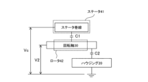
- FIG. 2 is a diagram conceptually illustrating an example of a principle of generation of a shaft voltage due to electrostatic capacitance inside an electric motor.
- FIG. 1 is a cross-sectional view showing the schematic configuration of an inverter-integrated electric compressor (hereinafter simply referred to as "electric compressor") according to one embodiment of the present invention.
- the electric compressor 10 according to the embodiment is configured to be incorporated, for example, in a refrigerant circuit of a vehicle air conditioner, and to compress, pressurize and discharge the gaseous refrigerant (i.e., fluid) flowing through the refrigerant circuit.
- the gaseous refrigerant flowing through the refrigerant circuit may contain a lubricant.
- the left side in FIG. 1 will be referred to as the front side of the electric compressor 10, the right side in FIG. 1 as the rear side of the electric compressor 10, the upper side in FIG. 1 as the upper side of the electric compressor 10, and the lower side in FIG. 1 as the lower side of the electric compressor 10.
- terms such as “first” and “second” are used simply to distinguish between similar elements and do not limit the elements to which they are attached.
- the electric compressor 10 includes a housing 20, a rotating shaft 30, an electric motor 40 that rotates the rotating shaft 30, a compression mechanism 50 that is driven by the rotation of the rotating shaft 30 to compress a gas refrigerant (fluid), and an inverter 60 that supplies power to the electric motor 40 to drive the electric motor 40.
- the rotating shaft 30, the electric motor 40, the compression mechanism 50, and the inverter 60 are contained in the housing 20.
- a scroll compression mechanism is used as the compression mechanism 50, and the compression mechanism 50 includes a fixed scroll 51 fixed to the housing 20, and a movable scroll 52 that revolves around the fixed scroll 51.
- the housing 20 is made of, for example, metal and is conductive.
- the housing 20 includes a front housing 21, a cover member 22, a center housing 23, and a rear housing 24 as housing components. These housing components are fastened together by fasteners (not shown) to form the housing 20 of the electric compressor 10.
- fasteners not shown
- the housing 20 can be formed from any combination of housing components.
- the front housing 21 has a cylindrical first peripheral wall portion 211 that extends forward and backward.
- the front end surface of the first peripheral wall portion 211 is the front end surface of the front housing 21, and the rear end surface of the first peripheral wall portion 211 is the rear end surface of the front housing 21.
- the inside of the first peripheral wall portion 211 is partitioned by a first partition portion 212 into a front inverter accommodating space in which the inverter 60 is accommodated, and a rear motor accommodating space in which the electric motor 40 is accommodated.
- the first partition portion 212 of the front housing 21 i.e., the housing 20 partitions the electric motor 40 and the inverter 60 within the housing 20.
- a first bearing retaining portion 213 is formed in the first partition portion 212.
- the first bearing retaining portion 213 is provided in approximately the center of the first partition portion 212 in the radial direction.
- the first bearing retaining portion 213 is formed in a cylindrical shape and protrudes rearward from the rear surface of the first partition portion 212, i.e., into the motor accommodating space.
- a first bearing 25 made of metal is retained in the first bearing retaining portion 213.
- the first bearing 25 is a rolling bearing and includes an inner ring, an outer ring, and a plurality of rolling elements arranged between them.
- the sliding portion of the first bearing 25 can be lubricated by a lubricant applied in advance and/or a lubricant contained in the gas refrigerant.
- a cover member 22 is joined to the front end face of the front housing 21. This closes off the inverter accommodating space to form an inverter accommodating chamber.
- the front end face of the center housing 23 is joined to the rear end face of the front housing 21. Furthermore, sealing members can be arranged between the front housing 21 and the cover member 22, and between the front housing 21 and the center housing 23, as necessary.
- the center housing 23 has a cylindrical second peripheral wall portion 231 that extends forward and backward.
- the front end surface of the second peripheral wall portion 231 is the front end surface of the center housing 23, and the rear end surface of the second peripheral wall portion 231 is the rear end surface of the center housing 23.
- the inside of the second peripheral wall portion 231 is partitioned by a second partition portion 232 into a front connection space that is connected to the motor housing space of the front housing 21, and a rear compression mechanism housing space in which the compression mechanism 50 is housed.
- the second partition portion 232 of the center housing 23 i.e., the housing 20 partitions the electric motor 40 and the compression mechanism 50 within the housing 20.
- the second partition wall portion 232 has a hollow protruding portion 233 having a cylindrical shape with a bottom.
- the bottom of the hollow protruding portion 233 faces forward, and protrudes forward, i.e., toward the motor housing space, relative to other portions of the second partition wall portion 232.
- the hollow protruding portion 233 is provided at approximately the center in the radial direction of the second partition wall portion 232 so as to face the first bearing retaining portion 213 provided in the first partition wall portion 212 of the front housing 21.
- a shaft insertion hole 234 through which the rotating shaft 30 is inserted is formed in the front flat portion (bottom of the cylindrical shape with a bottom) of the hollow protruding portion 233.
- a second bearing retaining portion 235 is formed inside the hollow protruding portion 233.
- the second bearing retaining portion 235 is provided on the compression mechanism 50 side relative to the shaft insertion hole 234.
- the second bearing retaining portion 235 retains the second bearing 26 made of metal.
- the second bearing 26 is a rolling bearing, similar to the first bearing 25. Similar to the sliding portion of the first bearing 25, the sliding portion of the second bearing 26 can be lubricated by a lubricant applied in advance and/or a lubricant contained in the gas refrigerant.
- the front end face of the rear housing 24 is joined to the rear end face of the center housing 23.
- the rear housing 24 is formed in a cylindrical shape with a bottom, and has a cylindrical third peripheral wall portion 241 that extends in the front-to-rear direction, and a bottom wall portion 242 that closes the rear opening of the third peripheral wall portion 241.
- the front end face, which is the opening end face of the third peripheral wall portion 241, is the front end face of the rear housing 24.
- a recess 236 is formed on the rear end surface of the center housing 23, i.e., the rear end surface of the second peripheral wall portion 231.
- This recess 236 can accommodate the outer edge portion of a first substrate 511 (described later) of the fixed scroll 51 that constitutes the compression mechanism 50 (scroll compression mechanism).
- the outer edge portion of the first substrate 511 of the fixed scroll 51 is sandwiched between the center housing 23 and the rear housing 24 while being accommodated in the recess 236.
- the fixed scroll 51 is fixed to the housing 20
- the rear opening of the center housing 23 (second peripheral wall portion 231) is closed by the first substrate 511 of the fixed scroll 51
- the open end surface (front opening) of the rear housing 24 (third peripheral wall portion 241) is closed by the first substrate 511 of the fixed scroll 51.
- the rotating shaft 30 is made of, for example, metal and is conductive.
- the rotating shaft 30 is inserted into a shaft insertion hole 234 formed in the hollow protrusion 233 of the second partition 232.
- the rotating shaft 30 passes through the shaft insertion hole 234 and extends in the front-rear direction inside the housing 20.
- the rotating shaft 30 is rotatably supported relative to the housing 20 by a first bearing 25 held by the first partition 212 (first bearing holding portion 213) and a second bearing 26 held by the second partition 232 (second bearing holding portion 235).
- a shaft seal member 27 is provided to block communication between the space on the electric motor 40 side (the motor housing space) and the space on the compression mechanism 50 side (the compression mechanism housing space) via the shaft insertion hole 234 in the housing 20.
- the shaft seal member 27 is held in a seal holder 237 formed inside the hollow protrusion 233 of the second partition wall 232.
- the seal holder 237 is provided between the shaft insertion hole 234 and the second bearing holder 235.
- the shaft seal member 27 is formed in an annular shape, and is configured such that the outer periphery is fixed to the seal holder 237 by, for example, press fitting, and the inner periphery is in contact (sliding contact) with the outer periphery of the rotating shaft 30.
- the shaft seal member 27 is disposed inside the hollow protruding portion 233 of the second partition wall portion 232, closer to the electric motor 40 than the second bearing 26, and more specifically, adjacent to the shaft insertion hole 234.
- the shaft seal member 27 seals between the electric motor 40 side and the compression mechanism 50 side in the axial direction of the rotating shaft 30, thereby blocking (substantially blocking) communication between the space on the electric motor 40 side (the motor accommodating space) and the space on the compression mechanism 50 side (the compression mechanism accommodating space) via the shaft insertion hole 234 inside the housing 20.
- the electric motor 40 is, for example, a three-phase AC motor.
- the electric motor 40 includes a stator 41 and a rotor 42. Both the stator 41 and the rotor 42 are electrically conductive.
- the stator 41 is fixed to the inner circumferential surface of the first peripheral wall portion 211 of the front housing 21 (i.e., the housing 20).
- the stator 41 includes a stator core and a stator winding. AC power is supplied to the stator winding from the inverter 60.
- the inverter 60 is configured to convert DC power from an on-board battery (not shown) or the like into AC power and supply it to the stator winding of the stator 41.
- the rotor 42 is disposed radially inside the stator 41 with a specified gap.
- a permanent magnet is built into the rotor 42.
- the rotor 42 is formed into a cylindrical shape overall, and is fixed to the rotating shaft 30 with the rotating shaft 30 inserted into its hollow portion, in other words, a through hole that passes through the rotor 42 in the front-rear direction. In other words, the rotor 42 is fixed to the outer peripheral surface of the rotating shaft 30 and rotates integrally with the rotating shaft 30.
- FIG. 2 is a diagram showing the rotating shaft 30 and the rotor 42 of the electric motor 40.
- an insulating layer 35 is provided between the rotating shaft 30 and the rotor 42.
- the insulating layer 35 may be formed of an electrically insulating resin such as a fluororesin or an epoxy resin.
- the insulating layer 35 may have a desired thickness.
- the rotor 42 is fixed to the outer peripheral surface of the rotating shaft 30 by pressing the rotating shaft 30 into the through hole 42a (hollow portion) of the rotor 42, and the insulating layer 35 is formed to cover the portion of the outer peripheral surface of the rotating shaft 30 that corresponds to the rotor 42.
- the peripheral portion 42b of the opening on the compression mechanism 50 side is chamfered more than the peripheral portion 42c of the opening on the inverter 60 side (including the case where only the peripheral portion 42b of the opening on the compression mechanism 50 side is chamfered).
- the electric motor 40 In the electric motor 40, a magnetic field is generated in the stator 41 by power supply from the inverter 60, and a rotational force acts on the permanent magnet of the rotor 42, causing the rotor 42 to rotate, thereby rotating the rotating shaft 30.
- the electric motor 40 is configured to be driven by the inverter 60 to rotate the rotating shaft 30.
- the compression mechanism 50 is a scroll compression mechanism, and includes a fixed scroll 51 and a movable scroll 52 that revolves around the fixed scroll 51.
- the fixed scroll 51 has a disk-shaped first base plate 511 and a first spiral wall 512 erected on one surface of the first base plate 511.
- the first spiral wall 512 extends in a spiral shape (involute curve shape) on the one surface of the first base plate 511 from the inner end (start of winding) on the radially inner side to the outer end (end of winding) on the radially outer side.
- the one surface of the first base plate 511 (the surface on which the first spiral wall 512 is erected) facing forward, the outer edge of the first base plate 511 is accommodated in the recess 236, and the fixed scroll 51 is sandwiched and fixed between the center housing 23 and the rear housing 24.
- the movable scroll 52 has a disk-shaped second substrate 521, a second spiral wall 522 erected on one surface of the second substrate 521, and a cylindrical portion 523 formed to protrude from the other surface of the second substrate 521.
- the second spiral wall 522 extends along a spiral shape (involute curve shape) on the one surface of the second substrate 521 from the inner end (start of winding) on the radially inner side to the outer end (end of winding) on the radially outer side.
- the movable scroll 52 is disposed between the second partition wall portion 232 of the center housing 23 and the fixed scroll 51 with the one surface of the second substrate 521 (the surface on which the second spiral wall 522 is erected) facing rearward.
- the movable scroll 52 is disposed opposite the fixed scroll 51 so that the second spiral wall 522 meshes with the first spiral wall 512 of the fixed scroll 51.
- the other surface of the second substrate 521 is also referred to as the back surface of the second substrate 521 or the back surface of the movable scroll 52.
- the movable scroll 52 is driven by a driving force transmitted via the rotating shaft 30 and the crank mechanism 70.
- the crank mechanism 70 is a mechanism that converts the rotation of the rotating shaft 30 into an orbital motion of the movable scroll 52.
- the driven movable scroll 52 performs an orbital motion relative to the fixed scroll 51 while its rotation is prevented by the rotation prevention mechanism 80.
- crank mechanism 70 may have a configuration including, for example, an eccentric pin provided eccentrically with respect to the rear end of the rotating shaft 30 with respect to the rotating shaft 30, and an eccentric bushing rotatably attached to the eccentric pin and rotatably inserted into the cylindrical portion 523 via a bearing.
- the rotation prevention mechanism 80 may have a configuration including, for example, a ring pressed into a circular hole formed in the other surface (back surface) of the second base plate 521 of the movable scroll 52, and a pin fixed to the second partition wall portion 232 of the center housing 23 and extending to the inside of the ring through the thrust plate 90.
- the compression mechanism 50 (scroll compression mechanism) is configured to take in and compress gaseous refrigerant by the movable scroll 52 revolving around the fixed scroll 51.
- An annular thrust plate 90 is disposed between the second base plate 521 of the movable scroll 52 and the second partition wall portion 232 of the center housing 23, and the rear surface of the second partition wall portion 232 receives the thrust force from the movable scroll 52 via the thrust plate 90.
- the electric compressor 10 has a suction chamber H1 into which gas refrigerant (fluid) flows in from the outside, a compression chamber H2 that compresses the gas refrigerant, a discharge chamber H3 from which the gas refrigerant compressed in the compression chamber H2 is discharged, a gas-liquid separation chamber H4 that separates lubricating oil from the gas refrigerant compressed in the compression chamber H2, and a back pressure chamber H5 provided on the back side of the second base plate 521 of the movable scroll 52.
- the suction chamber H1 is formed by the motor accommodating space of the front housing 21 and the connecting space of the center housing 23.
- the suction chamber H1 is defined by the first peripheral wall portion 211 of the front housing 21, the first partition wall portion 212 of the front housing 21, the second peripheral wall portion 231 of the center housing 23, and the second partition wall portion 232 of the center housing 23.
- the first peripheral wall portion 211 of the front housing 21 that defines the suction chamber H1 is formed with a suction port P1, and gas refrigerant from the outside flows into the suction chamber H1 through this suction port P1.
- the electric motor 40 and the first bearing 25 are disposed in the suction chamber H1.
- the center housing 23 is formed with a refrigerant passage L1 for guiding the gas refrigerant in the suction chamber H1 to the space H6 near the outer end of the compression mechanism 50 (scroll compression mechanism).
- Compression chamber H2 is formed between the fixed scroll 51 and the movable scroll 52.
- the compression mechanism 50 spiral compression mechanism
- the second spiral wall 522 comes into contact with the first spiral wall 512, and a crescent-shaped sealed space is formed radially outward by the first substrate 511, the first spiral wall 512, the second substrate 521, and the second spiral wall 522, and the formed crescent-shaped sealed space moves radially inward while gradually decreasing in volume.
- This crescent-shaped sealed space is the compression chamber H2.
- the discharge chamber H3 is defined by the third peripheral wall portion 241 of the rear housing 24, the bottom wall portion 242 of the rear housing 24, and the first base plate 511 of the fixed scroll 51.
- the inside of the third peripheral wall portion 241 of the rear housing 24 forms the discharge chamber H3.
- a discharge hole L2 is formed in the radial center of the first base plate 511 of the fixed scroll 51, which connects the compression chamber H2, which has moved to the innermost position and has a smaller volume, with the discharge chamber H3.
- a check valve (reed valve) 95 is provided in the discharge hole L2.
- the check valve 95 is configured to allow the flow of gas refrigerant from the compression chamber H2 to the discharge chamber H3, but to prevent the flow of gas refrigerant from the discharge chamber H3 to the compression chamber H2.
- the gas-liquid separation chamber H4 is located rearward of the discharge chamber H3. Specifically, the gas-liquid separation chamber H4 is formed in the bottom wall portion 242 of the rear housing 24 as a cylindrical space extending downward from the upper portion of the rear housing 24.
- the discharge chamber H3 and the gas-liquid separation chamber H4 are in communication with each other via a communication hole L3.
- An oil separator 100 that separates the lubricating oil contained in the gas refrigerant is disposed in the gas-liquid separation chamber H4.
- a discharge port P2 that is in communication with the gas-liquid separation chamber H4 is provided in the upper portion of the rear housing 24.
- the back pressure chamber H5 is defined by the second partition wall 232 of the center housing 23 and the second base plate 521 of the movable scroll 52.
- the back pressure chamber H5 is mainly formed by the internal space of the hollow protrusion 233 of the second partition wall 232.
- the second bearing 26, the shaft seal member 27, the crank mechanism 70, and the like are arranged in the back pressure chamber H5.
- the back pressure chamber H5 is connected to the discharge chamber H3 and the gas-liquid separation chamber H4 via a communication passage L4 formed in the center housing 23 and the rear housing 24, and an orifice (throttle portion) OL is arranged in the middle of the communication passage L4.
- the back pressure chamber H5 is connected to the suction chamber H1 via a pressure release passage in which an orifice or a back pressure control valve is provided in the middle.
- the electric motor 40 rotates the rotating shaft 30 by power supply from the inverter 60
- the rotation of the rotating shaft 30 is transmitted to the compression mechanism 50 (more specifically, the movable scroll 52) via the crank mechanism 70, and the movable scroll 52 performs an orbital motion relative to the fixed scroll 51.
- the gas refrigerant (low pressure) flows into the suction chamber H1 via the suction port P1
- passes through the electric motor 40 and the refrigerant passage L1 reaches the space H6, and is taken into the compression chamber H2 formed between the fixed scroll 51 and the movable scroll 52 and compressed.
- the gas refrigerant (high pressure) compressed in the compression chamber H2 is discharged into the discharge chamber H3 via the discharge hole L2 (and the check valve 95), and then flows into the gas-liquid separation chamber H4 via the communication hole L3.
- the lubricating oil contained in the gas refrigerant that flows into the gas-liquid separation chamber H4 is separated by the oil separator 100.
- the gas refrigerant (high pressure) after the lubricating oil is separated by the oil separator 100 is discharged from the discharge port P2.
- the lubricating oil separated from the gas refrigerant by the oil separator 100 is stored at the bottom of the gas-liquid separation chamber H4. Also, a portion of the lubricating oil contained in the gas refrigerant discharged to the discharge chamber H3 is stored at the bottom of the discharge chamber H3.
- the back pressure chamber H5 is connected to the discharge chamber H3 and the gas-liquid separation chamber H4 via the communication passage L4.
- the back pressure chamber H5 is also connected to the suction chamber H1 via the shaft insertion hole 234 and the pressure release passage.
- the discharge chamber H3 and the gas-liquid separation chamber H4 are at high pressure, and the suction chamber H1 is at low pressure. Therefore, the lubricating oil stored at the bottom of the discharge chamber H3 and/or the bottom of the gas-liquid separation chamber H4 is supplied to the back pressure chamber H5 via the communication passage L4 together with the gas refrigerant in the discharge chamber H3 and/or the gas-liquid separation chamber H4, and is reduced in pressure by passing through the orifice OL.
- the conductive rotating shaft 30 to which the rotor 42 of the electric motor 40 is fixed is rotatably supported by a first metallic bearing 25 held in a first partition wall portion 212 of the front housing 21 constituting the conductive housing 20, and a second metallic bearing 26 held in a second partition wall portion 232 of the center housing 23 constituting the housing 20.
- the first partition wall portion 212 separates the inverter 60 and the electric motor 40 within the housing 20, and the second partition wall portion 232 separates the electric motor 40 and the compression mechanism 50 within the housing 20, and the first bearing 25 and the second bearing 26 are rolling bearings.
- the electric motor 40 is driven by the inverter 60. Therefore, by switching the switching elements of the inverter 60, as shown in FIG. 3, a common mode voltage Vc is applied to the stator winding of the stator 41 of the electric motor 40.
- the first capacitance C1 is mainly the capacitance between the stator winding and the rotor 42
- the second capacitance is mainly the capacitance of an insulating film due to the lubricant in the first bearing 25 and/or the second bearing 26.
- an insulating layer 35 is provided between the rotating shaft 30 and the rotor 42.
- the capacitance of the insulating layer 35 is added (connected) in series to the capacitance between the stator winding and the rotor 42 between the stator winding and the rotating shaft 30. Therefore, the capacitance of the insulating layer 35 can adjust or even reduce the voltage share V2 of the second capacitance C2, i.e., the shaft voltage generated between the rotating shaft 30 and the housing 20.
- the electric compressor 10 by reducing the shaft voltage generated between the rotating shaft 30 and the housing 20 by the insulating layer 35 compared to the conventional case, it is possible to suppress or prevent discharge inside the first bearing 25 and/or the second bearing 26, and thus electrolytic corrosion of the first bearing 25 and/or the second bearing 26, and as a result, stable operation over a long period of time is possible.
- the rotor 42 is fixed to the outer circumferential surface of the rotating shaft 30 by pressing the rotating shaft 30 into the through hole 42a of the rotor 42, and the insulating layer 35 is formed so as to cover the portion of the outer circumferential surface of the rotating shaft 30 that corresponds to the rotor 42. Therefore, it is relatively easy to provide the insulating layer 35 between the rotating shaft 30 and the rotor 42.
- a scroll compression mechanism is used as the compression mechanism 50.
- the compression mechanism 50 is a scroll compression mechanism
- the rotating shaft 30 is often formed with a larger diameter on the compression mechanism 50 side than on the opposite side (the inverter 60 side). Therefore, when the rotor 42 is fixed to the outer circumferential surface of the rotating shaft 30, the rotating shaft 30 is inserted from the opening on the compression mechanism 50 side of the two openings (the opening on the inverter 60 side and the opening on the compression mechanism 50 side) of the through hole 42a (hollow portion) of the rotor 42.
- the peripheral portion 42b of the opening on the compression mechanism 50 side is chamfered more than the peripheral portion 42c of the opening on the inverter 60 side. Therefore, the chamfered peripheral portion 42b of the opening on the compression mechanism 50 side functions as a guide, making it easy to insert the rotating shaft 30 into the through hole 42a (hollow portion) of the rotor 42, and also suppressing or preventing damage to the insulating layer 35 when the rotating shaft 30 and the rotor 42 are integrated.
- the insulating layer 35 is formed to cover the portion of the outer circumferential surface of the rotating shaft 30 that corresponds to the rotor 42.
- the insulating layer 35 may be provided to cover the inner circumferential surface of the rotor 42.
- the insulating layer 35 may be formed as an insulating coating that covers the entire outer circumferential surface of the rotating shaft 30.
- the entire outer circumferential surface of the rotating shaft 30 may be covered with an insulating coating, and the insulating layer 35 may be provided on the portion of the outer circumferential surface of the rotating shaft 30 that corresponds to the rotor 42, separately from the insulating coating.
- first bearing 25 and the second bearing 26 are used as the first bearing 25 and the second bearing 26.
- first bearing 25 and the second bearing 26 do not necessarily have to be rolling bearings.
- at least one of the first bearing 25 and the second bearing 26 may be formed of a metallic sliding bearing. In this case, discharge between the rotating shaft 30 and at least one of the first bearing 25 and the second bearing 26, and thus electrolytic corrosion of the first bearing 25 and the second bearing 26, can be suppressed or prevented.
- the shaft seal member 27 may be conductive.
- the shaft seal member 27 includes, for example, a metal core material and a conductive resin that at least partially covers the surface of the core material, and the conductive resin can form a lip portion as an inner peripheral portion that contacts (sliding contacts) the outer peripheral surface of the rotating shaft 30.
- the shaft seal member 27 electrically connects the rotating shaft 30 and the second partition wall portion 232 (i.e., the housing 20), so that the electric charge generated on the rotating shaft 30 can be released to the housing 20 without passing through the first bearing 25 or the second bearing 26. Therefore, the occurrence of discharge inside the first bearing 25 and the second bearing 26, and thus the electrolytic corrosion of the first bearing 25 and the second bearing 26 can be more effectively suppressed or prevented.
Landscapes
- Engineering & Computer Science (AREA)
- Mechanical Engineering (AREA)
- General Engineering & Computer Science (AREA)
- Applications Or Details Of Rotary Compressors (AREA)
- Compressor (AREA)
- Rotary Pumps (AREA)
Abstract
【課題】電動モータのロータが固定された回転軸を回転可能に支持する軸受の電食を抑制又は防止することができるインバータ一体型電動圧縮機を提供する。 【解決手段】インバータ一体型電動圧縮機10において、導電性を有するハウジング20の第1隔壁部212はインバータ60と電動モータ40との間を仕切り、ハウジング20の第2隔壁部232は電動モータ40と圧縮機構50との間を仕切っている。電動モータ40のステータ41はハウジング20に固定され、電動モータ40のロータ42が固定された導電性の回転軸30は、第1隔壁部212に保持された金属製の第1軸受25と第2隔壁部232に保持された金属製の第2軸受26とによって回転可能に支持されている。また、回転軸30とロータ42との間には絶縁層35が設けられている。
Description
本発明は、インバータ一体型電動圧縮機に関する。
電動圧縮機の一例として従来からインバータ一体型電動圧縮機が知られている。この種の電動圧縮機においては、金属製の回転軸(駆動軸)、回転軸を回転させる電動モータ、回転軸の回転によって駆動される圧縮機構、及び電動モータを駆動するインバータが金属製のハウジング内に一体的に組み込まれていることが多い。
インバータによって電動モータが駆動される場合、回転軸とこれを支持する金属製の軸受を保持するハウジングとの間には電動モータ内の静電容量によって軸電圧が発生する。この軸電圧が例えば潤滑剤による絶縁膜の絶縁破壊電圧を超えると、回転軸と軸受との間や軸受内部で放電が起こり、その結果、軸受に電食が発生するおそれがある。
そこで、本発明は、電動モータのロータが固定された回転軸を回転可能に支持する金属製の軸受の電食を抑制又は防止することができるインバータ一体型電動圧縮機を提供することを目的とする。
本発明の一側面によると、インバータ一体型電動圧縮機が提供される。提供されるインバータ一体型電動圧縮機は、導電性の回転軸と、前記回転軸を回転させる電動モータと、前記回転軸の回転によって駆動されて流体を圧縮する圧縮機構と、前記電動モータを駆動するインバータと、これらを収容する導電性のハウジングとを含む。前記ハウジングは、前記インバータと前記電動モータとの間を仕切る第1隔壁部と、前記電動モータと前記圧縮機構との間を仕切る第2隔壁部とを有する。前記電動モータは、前記ハウジングに固定されたステータと前記回転軸に固定されたロータとを含む。前記回転軸は、前記第1隔壁部に保持された金属製の第1軸受と前記第2隔壁部に保持された金属製の第2軸受とによって回転可能に支持されている。また、前記回転軸と前記ロータとの間には絶縁層が設けられている。
本発明の一側面によれば、電動モータのロータが固定された回転軸を回転可能に支持する軸受の電食を抑制又は防止することができるインバータ一体型電動圧縮機を提供することができる。
以下、本発明の実施の形態を添付図面に基づいて説明する。
図1は、本発明の一実施形態に係るインバータ一体型電動圧縮機(以下単に「電動圧縮機」という。)の概略構成を示す断面図である。実施形態に係る電動圧縮機10は、例えば、車両用空調装置の冷媒回路に組み込まれ、冷媒回路を流れる気体冷媒(つまり、流体)を圧縮し、高圧化して吐出するように構成される。ここで、前記冷媒回路を流れる気体冷媒には潤滑剤が含まれ得る。
なお、以下においては、図1における左側を電動圧縮機10の前側、図1における右側を電動圧縮機10の後側、図1における上側を電動圧縮機10の上側、図1における下側を電動圧縮機10の下側として説明する。また、「第1」、「第2」などの用語は、単に類似の要素を区別するために用いられ、それらが付された要素を限定するものではない。
電動圧縮機10は、ハウジング20と、回転軸30と、回転軸30を回転させる電動モータ40と、回転軸30の回転によって駆動されて気体冷媒(流体)を圧縮する圧縮機構50と、電動モータ40に給電して電動モータ40を駆動するインバータ60とを含む。回転軸30、電動モータ40、圧縮機構50及びインバータ60は、ハウジング20に収容されている。特に限定されないが、本実施形態においては、スクロール圧縮機構が圧縮機構50として採用されており、圧縮機構50は、ハウジング20に固定された固定スクロール51と、固定スクロール51に対して公転旋回運転を行う可動スクロール52とを含む。
ハウジング20は、例えば金属製であり、導電性を有する。本実施形態において、ハウジング20は、フロントハウジング21、カバー部材22、センターハウジング23及びリアハウジング24をハウジング構成要素として含む。そして、これらハウジング構成要素が図示省略の締結具などによって締結されて電動圧縮機10のハウジング20が形成されている。但し、これに限られるものではなく、ハウジング20は、任意のハウジング構成要素の組み合わせで形成され得る。
フロントハウジング21は、前後に延びる円筒状の第1周壁部211を有する。第1周壁部211の前端面がフロントハウジング21の前端面であり、第1周壁部211の後端面がフロントハウジング21の後端面である。第1周壁部211の内部は、第1隔壁部212により、インバータ60が収容される前側のインバータ収容空間と、電動モータ40が収容される後側のモータ収容空間とに仕切られている。換言すれば、フロントハウジング21(つまり、ハウジング20)の第1隔壁部212は、ハウジング20内において電動モータ40とインバータ60との間を仕切っている。
第1隔壁部212には第1軸受保持部213が形成されている。第1軸受保持部213は、第1隔壁部212の径方向略中央に設けられている。第1軸受保持部213は、円筒状に形成され、第1隔壁部212の後側の面から後方に、すなわち、前記モータ収容空間内に突出している。第1軸受保持部213には金属製の第1軸受25が保持されている。本実施形態において、第1軸受25は、転がり軸受であり、内輪、外輪、及びそれらの間に配置された複数の転動体を含む。第1軸受25の摺動部は、あらかじめ付与された潤滑剤及び/又は前記気体冷媒に含まれる潤滑剤によって潤滑され得る。
フロントハウジング21の前端面にはカバー部材22が接合されている。これにより、前記インバータ収容空間が閉塞されてインバータ収容室が形成されている。フロントハウジング21の後端面にはセンターハウジング23の前端面が接合されている。なお、フロントハウジング21とカバー部材22との間、及び、フロントハウジング21とセンターハウジング23との間には必要に応じてシール部材が配置され得る。
センターハウジング23は、前後に延びる円筒状の第2周壁部231を有する。第2周壁部231の前端面がセンターハウジング23の前端面であり、第2周壁部231の後端面がセンターハウジング23の後端面である。第2周壁部231の内部は、第2隔壁部232により、フロントハウジング21の前記モータ収容空間に繋がる前側の接続空間と、圧縮機構50が収容される後側の圧縮機構収容空間とに仕切られている。換言すれば、センターハウジング23(つまり、ハウジング20)の第2隔壁部232は、ハウジング20内において電動モータ40と圧縮機構50との間を仕切っている。
第2隔壁部232は、有底円筒状の中空突出部233を有する。中空突出部233は、底部が前方を向いており、第2隔壁部232の他の部位に対して、前方に、すなわち、前記モータ収容空間側に突出している。中空突出部233は、フロントハウジング21の第1隔壁部212に設けられた第1軸受保持部213に対向するように、第2隔壁部232の径方向略中央に設けられている。中空突出部233の前側平坦部(有底円筒状の底部)には回転軸30が挿通される軸挿通孔234が形成されている。また、中空突出部233の内部には第2軸受保持部235が形成されている。つまり、第2軸受保持部235は、軸挿通孔234よりも圧縮機構50側に設けられている。第2軸受保持部235には金属製の第2軸受26が保持されている。本実施形態において、第2軸受26は、第1軸受25と同様、転がり軸受である。第1軸受25の摺動部と同様、第2軸受26の摺動部は、あらかじめ付与された潤滑剤及び/又は前記気体冷媒に含まれる潤滑剤によって潤滑され得る。
センターハウジング23の後端面にはリアハウジング24の前端面が接合されている。リアハウジング24は、有底円筒状に形成され、前後に延びる円筒状の第3周壁部241と、第3周壁部241の後側の開口を閉塞する底壁部242とを有する。第3周壁部241の開口端面である前端面がリアハウジング24の前端面である。
本実施形態において、センターハウジング23の後端面、すなわち、第2周壁部231の後端面には凹部236が形成されている。この凹部236は、圧縮機構50(スクロール圧縮機構)を構成する固定スクロール51の第1基板511(後述する)の外縁部を収容可能である。そして、固定スクロール51の第1基板511の外縁部が、凹部236に収容された状態でセンターハウジング23とリアハウジング24とに挟持されている。これにより、固定スクロール51がハウジング20に固定され、センターハウジング23(第2周壁部231)の後側の開口が固定スクロール51の第1基板511で閉塞され、及び、リアハウジング24(第3周壁部241)の開口端面(前側の開口)が固定スクロール51の第1基板511で閉塞される。
回転軸30は、例えば金属製であり、導電性を有する。回転軸30は、第2隔壁部232の中空突出部233に形成された軸挿通孔234に挿通されている。換言すれば、回転軸30は、軸挿通孔234を貫通してハウジング20内を前後方向に延びている。また、回転軸30は、第1隔壁部212(の第1軸受保持部213)に保持された第1軸受25と、第2隔壁部232(の第2軸受保持部235)に保持された第2軸受26とによってハウジング20に対して回転可能に支持されている。
ここで、本実施形態では、ハウジング20内における軸挿通孔234を介した電動モータ40側の空間(前記モータ収容空間)と圧縮機構50側の空間(前記圧縮機構収容空間)との連通を遮断するため、軸シール部材27が設けられている。軸シール部材27は、第2隔壁部232の中空突出部233の内部に形成されたシール保持部237に保持されている。シール保持部237は、軸挿通孔234と第2軸受保持部235との間に設けられている。軸シール部材27は、円環状に形成され、外周部がシール保持部237に例えば圧入によって固定され、内周部が回転軸30の外周面に接触(摺動接触)するように構成されている。
つまり、軸シール部材27は、第2隔壁部232の中空突出部233の内部において、第2軸受26よりも電動モータ40側に、さらに言えば、軸挿通孔234に隣接して配置されている。そして、軸シール部材27は、回転軸30の軸方向における電動モータ40側と圧縮機構50側との間をシールし、これによって、ハウジング20内における軸挿通孔234を介した電動モータ40側の空間(前記モータ収容空間)と圧縮機構50側の空間(前記圧縮機構収容空間)との連通を遮断(実質的に遮断)している。
電動モータ40は、例えば三相交流モータである。電動モータ40は、ステータ41及びロータ42を含む。ステータ41及びロータ42は、いずれも導電性を有する。
ステータ41は、フロントハウジング21の第1周壁部211の内周面(つまり、ハウジング20)に固定されている。ステータ41は、ステータコアと、ステータ巻線とを含む。ステータ巻線にはインバータ60から交流電力が供給される。インバータ60は、図示しない車載バッテリなどからの直流電力を交流電力に変換してステータ41のステータ巻線に供給するように構成されている。
ロータ42は、ステータ41の径方向内側に所定の隙間を有して配置されている。ロータ42には永久磁石が組み込まれている。ロータ42は、全体として円筒状に形成され、その中空部、換言すれば、ロータ42を前後方向に貫通する貫通孔に回転軸30が挿通された状態で回転軸30に固定されている。つまり、ロータ42は、回転軸30の外周面に固定されて、回転軸30と一体に回転する。
図2は、回転軸30及び電動モータ40のロータ42を示す図である。図2に示されるように、本実施形態においては、回転軸30とロータ42との間に絶縁層35が設けられている。特に限定されないが、絶縁層35は、フッ素樹脂やエポキシ樹脂などの電気絶縁性樹脂で形成され得る。また、絶縁層35は、所望の厚さを有し得る。
本実施形態において、ロータ42は、回転軸30がロータ42の貫通孔42a(中空部)に圧入されることによって回転軸30に外周面に固定されており、絶縁層35は、回転軸30の外周面のロータ42に対応する部分を覆うように形成されている。また、ロータ42の貫通孔42a(中空部)の2つの開口、すなわち、インバータ60側の開口(前側開口)及び圧縮機構50側の開口(後側開口)のうち、圧縮機構50側の開口の周縁部42bがインバータ60側の開口の周縁部42cに比べて大きく面取りされている(圧縮機構50側の開口の周縁部42bのみが面取りされている場合を含む)。
電動モータ40は、インバータ60からの給電によってステータ41に磁界が発生し、ロータ42の永久磁石に回転力が作用してロータ42が回転し、これによって、回転軸30を回転させる。つまり、電動モータ40は、インバータ60によって駆動されて回転軸30を回転させるように構成されている。
圧縮機構50は、上述のように、スクロール圧縮機構であり、固定スクロール51と、固定スクロール51に対して公転旋回運転を行う可動スクロール52とを含む。
固定スクロール51は、円板状の第1基板511と、第1基板511の一方の面に立設された第1渦巻壁512とを有する。第1渦巻壁512は、第1基板511の前記一方の面上を径方向内側の内端部(巻き初め部)から径方向外側の外端部(巻き終わり部)まで渦巻状(インボリュート曲線状)に延びている。固定スクロール51は、第1基板511の前記一方の面(第1渦巻壁512が立設された面)が前方を向いた状態で第1基板511の外縁部が凹部236に収容され、センターハウジング23とリアハウジング24とに挟持されて固定されている。
可動スクロール52は、円板状の第2基板521と、第2基板521の一方の面に立設された第2渦巻壁522と、第2基板521の他方の面に突出形成された円筒部523とを有する。第2渦巻壁522は、第2基板521の前記一方の面上を径方向内側の内端部(巻き初め部)から径方向外側の外端部(巻き終わり部)まで渦巻状(インボリュート曲線状)に沿って延びている。可動スクロール52は、第2基板521の前記一方の面(第2渦巻壁522が立設された面)が後方を向いた状態でセンターハウジング23の第2隔壁部232と固定スクロール51との間に配置されている。換言すれば、可動スクロール52は、第2渦巻壁522が固定スクロール51の第1渦巻壁512に噛み合うように、固定スクロール51に対向配置されている。なお、第2基板521の前記他方の面は、第2基板521の背面又は可動スクロール52の背面とも称される。
可動スクロール52は、回転軸30及びクランク機構70を介して伝達される駆動力によって駆動される。クランク機構70は、回転軸30の回転を可動スクロール52の公転旋回運動に変換する機構である。駆動された可動スクロール52は、自転阻止機構80によって自転が阻止された状態で、固定スクロール51に対して公転旋回運動を行う。
特に限定されないが、クランク機構70は、例えば、回転軸30の後端に回転軸30に対して偏心して設けられた偏心ピンと、偏心ピンに回転可能に取り付けられ且つ軸受を介して円筒部523に回転可能に挿入された偏心ブッシュとを含む構成を有し得る。また、自転阻止機構80は、例えば、可動スクロール52の第2基板521の前記他方の面(背面)に形成された円形穴に圧入されたリングと、センターハウジング23の第2隔壁部232に固定され且つスラストプレート90を貫通してリングの内側まで延びるピンとを含む構成を有し得る。
圧縮機構50(スクロール圧縮機構)は、可動スクロール52が固定スクロール51に対して公転旋回運動を行うことで気体冷媒を取り込んで圧縮するように構成されている。なお、可動スクロール52の第2基板521とセンターハウジング23の第2隔壁部232との間には円環板状のスラストプレート90が配置されており、第2隔壁部232の後側の面がスラストプレート90を介して可動スクロール52からのスラスト力を受けるようになっている。
また、図1に示されるように、実施形態に係る電動圧縮機10は、外部から気体冷媒(流体)が流入する吸入室H1と、気体冷媒を圧縮する圧縮室H2と、圧縮室H2で圧縮された気体冷媒が吐出される吐出室H3と、圧縮室H2で圧縮された気体冷媒から潤滑油を分離する気液分離室H4と、可動スクロール52の第2基板521の背面側に設けられた背圧室H5とを有する。
吸入室H1は、フロントハウジング21の前記モータ収容空間とセンターハウジング23の前記接続空間とによって形成されている。換言すれば、吸入室H1は、フロントハウジング21の第1周壁部211、フロントハウジング21の第1隔壁部212、センターハウジング23の第2周壁部231及びセンターハウジング23の第2隔壁部232によって画成されている。吸入室H1を画成するフロントハウジング21の第1周壁部211には吸入口P1が形成されており、この吸入口P1を介して外部からの気体冷媒が吸入室H1に流入する。吸入室H1には、電動モータ40及び第1軸受25が配置されている。また、センターハウジング23には、吸入室H1内の気体冷媒を圧縮機構50(スクロール圧縮機構)の外端部近傍の空間H6に導くための冷媒通路L1が形成されている。
圧縮室H2は、固定スクロール51と可動スクロール52との間に形成される。圧縮機構50(スクロール圧縮機構)においては、可動スクロール52が固定スクロール51に対して公転旋回運動を行うと、第2渦巻壁522が第1渦巻壁512に接触し、第1基板511、第1渦巻壁512、第2基板521及び第2渦巻壁522によって三日月状の密閉空間が径方向外側で形成され、形成された三日月状の密閉空間は、容積を徐々に減少させながら径方向内側へと移動する。この三日月状の密閉空間が圧縮室H2である。
吐出室H3は、リアハウジング24の第3周壁部241と、リアハウジング24の底壁部242と、固定スクロール51の第1基板511とによって画成されている。つまり、リアハウジング24の第3周壁部241の内部が吐出室H3となっている。固定スクロール51の第1基板511の径方向中央には、最も内側に移動して容積が小さくなった圧縮室H2と、吐出室H3とを連通する吐出孔L2が形成されている。吐出孔L2には、逆止弁(リード弁)95が設けられている。逆止弁95は、圧縮室H2から吐出室H3への気体冷媒の流通を許容するが、吐出室H3から圧縮室H2への気体冷媒の流通を阻止するように構成されている。
気液分離室H4は、吐出室H3よりも後側に設けられている。具体的には、気液分離室H4は、リアハウジング24の上部から下方に延びる円柱状の空間としてリアハウジング24の底壁部242に形成されている。吐出室H3と気液分離室H4とは連通孔L3を介して連通している。気液分離室H4には、気体冷媒に含まれる潤滑油を分離するオイルセパレータ100が配置されている。リアハウジング24の上部には、気液分離室H4に連通する吐出口P2が設けられている。
背圧室H5は、センターハウジング23の第2隔壁部232と可動スクロール52の第2基板521とによって画成されている。換言すれば、本実施形態において、背圧室H5は、主に第2隔壁部232の中空突出部233の内部空間によって形成されている。背圧室H5には、第2軸受26、軸シール部材27及びクランク機構70などが配置されている。背圧室H5は、センターハウジング23及びリアハウジング24に形成された連通路L4を介して吐出室H3及び気液分離室H4に連通しており、連通路L4の途中にはオリフィス(絞り部)OLが配置されている。なお、図示省略するが、背圧室H5は、オリフィスや背圧制御弁がその途中に設けられた放圧通路を介して吸入室H1に連通している。
ここで、電動圧縮機10の動作を簡単に説明する。
インバータ60からの給電によって電動モータ40が回転軸30を回転させると、回転軸30の回転がクランク機構70を介して圧縮機構50(より具体的には可動スクロール52)に伝達され、可動スクロール52が固定スクロール51に対して公転旋回運動を行う。すると、気体冷媒(低圧)が吸入口P1を介して吸入室H1に流入し、電動モータ40及び冷媒通路L1を通過して空間H6に至り、固定スクロール51と可動スクロール52との間に形成される圧縮室H2に取り込まれて圧縮される。圧縮室H2で圧縮された気体冷媒(高圧)は、吐出孔L2(及び逆止弁95)を介して吐出室H3に吐出され、その後、連通孔L3を介して気液分離室H4に流入する。気液分離室H4に流入した気体冷媒は、オイルセパレータ100によって、そこに含まれた潤滑油が分離される。そして、オイルセパレータ100によって潤滑油が分離された後の気体冷媒(高圧)は、吐出口P2から吐出される。オイルセパレータ100によって気体冷媒から分離された潤滑油は、気液分離室H4の底部に貯留される。また、吐出室H3に吐出された気体冷媒に含まれた潤滑油の一部は、吐出室H3の底部に貯留される。
背圧室H5は、連通路L4を介して吐出室H3及び気液分離室H4に連通している。また、背圧室H5は、軸挿通孔234及び前記放圧通路を介して吸入室H1にも連通している。吐出室H3及び気液分離室H4は高圧であり、吸入室H1は低圧である。そのため、吐出室H3の底部及び/又は気液分離室H4の底部に貯留された潤滑油は、吐出室H3内及び/又は気液分離室H4内の気体冷媒と共に、連通路L4を介して背圧室H5に供給され、その際に、オリフィスOLを通過することによって減圧される。また、背圧室H5内の潤滑油及び/又は気体冷媒は、軸シール部材27と、前記放圧通路に設けられたオリフィスや背圧制御弁とによって、吸入室H1への流出が制限される。そのため、背圧室H5の圧力は、吸入室H1の圧力Psと吐出室H3の圧力Pd(=気液分離室H4の圧力)との間の中間圧力Pmに保持され、この中間圧力Pmによって可動スクロール52が固定スクロール51に向けて押し付けられる。つまり、背圧室H5は、可動スクロール52に対して固定スクロール51に向けて押し付ける方向の圧力を作用させる。
以上説明したように、実施形態に係る電動圧縮機10において、電動モータ40のロータ42が固定された導電性の回転軸30は、導電性のハウジング20を構成するフロントハウジング21の第1隔壁部212に保持された金属製の第1軸受25と、ハウジング20を構成するセンターハウジング23の第2隔壁部232に保持された金属製の第2軸受26とによって回転可能に支持されている。第1隔壁部212は、ハウジング20内においてインバータ60と電動モータ40との間を仕切っており、第2隔壁部232は、ハウジング20内において電動モータ40と圧縮機構50との間を仕切っており、第1軸受25及び第2軸受26は、転がり軸受である。
また、実施形態に係る電動圧縮機10において、電動モータ40はインバータ60によって駆動される。そのため、インバータ60のスイッチング素子のスイッチングにより、図3に示されるように、電動モータ40のステータ41の前記ステータ巻線にはコモンモード電圧Vcが印加される。このコモンモード電圧Vcは、例えば、前記ステータ巻線と回転軸30との間の第1静電容量C1と、回転軸30とこれを支持する軸受(第1軸受25、第2軸受26)を保持するハウジング20との間の第2静電容量C2とで分圧され、第2静電容量C2の電圧分担分V2(=Vc×C1/(C1+C2))が回転軸30とハウジング20との間に軸電圧として発生する。第1静電容量C1は、主に前記ステータ巻線とロータ42との間の静電容量であり、前記第2静電容量は、主に第1軸受25内及び/又は第2軸受26内の潤滑剤による絶縁膜の静電容量である。そして、既述のように、回転軸30とハウジング20との間の軸電圧が潤滑剤による絶縁膜の絶縁破壊電圧を超えると、第1軸受25及び/又は第2軸受26の内部で放電が起こり、その結果、第1軸受25及び/又は第2軸受26に電食が発生するおそれがある。
この点、本実施形態においては、回転軸30とロータ42との間に絶縁層35が設けられている。つまり、前記ステータ巻線と回転軸30との間において、前記ステータ巻線とロータ42との間の静電容量に絶縁層35の静電容量が直列に追加(接続)された形となっている。そのため、絶縁層35の静電容量によって、第2静電容量C2の電圧分担分V2、すなわち、回転軸30とハウジング20との間に発生する軸電圧を調整すること、さらに言えば、小さくすることが可能である。したがって、実施形態に係る電動圧縮機10によれば、絶縁層35によって回転軸30とハウジング20との間に発生する軸電圧を従来に比べて小さくすることで、第1軸受25及び/又は第2軸受26の内部で放電が起こること、ひいては、第1軸受25及び/又は第2軸受26の電食を抑制又は防止することができ、その結果、長期間にわたる安定した運転が可能になる。
また、本実施形態において、ロータ42は、回転軸30がロータ42の貫通孔42aに圧入されることによって回転軸30に外周面に固定されており、絶縁層35は、回転軸30の外周面のロータ42に対応する部分を覆うように形成されている。そのため、回転軸30とロータ42との間に絶縁層35が設けることが比較的容易である。
また、本実施形態ではスクロール圧縮機構が圧縮機構50として採用されている。圧縮機構50がスクロール圧縮機構である場合、回転軸30は、圧縮機構50側がその反対側(インバータ60側)に比べて大径に形成されることが多い。そのため、ロータ42を回転軸30の外周面に固定する際、回転軸30は、ロータ42の貫通孔42a(中空部)の2つの開口(インバータ60側の開口及び圧縮機構50側の開口)のうち、圧縮機構50側の開口から挿入されることになる。
この点、本実施形態においては、ロータ42の貫通孔42a(中空部)の2つの開口のうち、圧縮機構50側の開口の周縁部42bがインバータ60側の開口の周縁部42cに比べて大きく面取りされている。そのため、面取りされた圧縮機構50側の開口の周縁部42bがガイドとして機能し、ロータ42の貫通孔42a(中空部)への回転軸30の挿入が容易に行えると共に、回転軸30とロータ42とを一体化する際に絶縁層35が損傷することも抑制又は防止され得る。
なお、上述の実施形態において、絶縁層35は、回転軸30の外周面のロータ42に対応する部分を覆うように形成されている。しかし、これに限られるものではない。絶縁層35は、ロータ42の内周面を覆うように設けられてもよい。あるいは、絶縁層35は、回転軸30の外周面全体を覆う絶縁被膜として形成されてもよい。さらに、回転軸30の外周面全体が絶縁被膜で覆われると共に、前記絶縁被膜とは別に回転軸30の外周面のロータ42に対応する部分に絶縁層35が設けられてもよい。このようにすると、回転軸30から第1軸受25又は第2軸受26に電流が流れないようにすることができ、第1軸受25及び/又は第2軸受26の内部で放電が起こること、ひいては、第1軸受25及び第2軸受26の電食がさらに効果的に抑制又は防止され得る。
また、上述の実施形態においては、第1軸受25及び第2軸受26として金属製の転がり軸受が採用されている。しかし、第1軸受25及び第2軸受26は、必ずしも転がり軸受である必要はない。例えば、第1軸受25及び第2軸受26の少なくとも一方が金属製の滑り軸受で形成されてもよい。この場合、回転軸30と第1軸受25及び第2軸受26の少なくとも一方との間で放電が起こること、ひいては、第1軸受25及び第2軸受26の電食が抑制又は防止され得る。
さらに、軸シール部材27が導電性を有してもよい。この場合、軸シール部材27は、例えば、金属製の芯材と、芯材の表面を少なくとも部分的に覆う導電性樹脂とを含み、導電性樹脂によって、回転軸30の外周面に接触(摺動接触)する内周部としてのリップ部が形成され得る。このようにすると、軸シール部材27によって回転軸30と第2隔壁部232(すなわち、ハウジング20)とが電気的に導通されるので、回転軸30に発生した電荷を第1軸受25や第2軸受26を介さずにハウジング20に逃がすことができる。したがって、第1軸受25及び第2軸受26の内部で放電が起こること、ひいては、第1軸受25及び第2軸受26の電食がさらに効果的に抑制又は防止され得る。
以上、本発明の実施形態及び変形例について説明したが、本発明は、上述の実施形態や変形例に制限されるものではなく、本発明の技術的思想に基づいてさらなる変形や変更が可能であることはもちろんである。
10…インバータ一体型電動圧縮機、20…ハウジング、25…第1軸受、26…第2軸受、27…軸シール部材、30…回転軸、35…絶縁層、40…電動モータ、41…ステータ、42…ロータ、42a…貫通孔、42b,42c…周縁部、50…圧縮機構、51…固定スクロール、52…可動スクロール、60…インバータ、212…第1隔壁部、213…第1軸受保持部、232…第2隔壁部、233…中空突出部、234…軸挿通孔、235…第2軸受保持部、237…シール保持部、H1…吸入室、H2…圧縮室、H3…吐出室、H5…背圧室
Claims (4)
- 導電性の回転軸と、前記回転軸を回転させる電動モータと、前記回転軸の回転によって駆動されて流体を圧縮する圧縮機構と、前記電動モータを駆動するインバータと、これらを収容する導電性のハウジングとを含むインバータ一体型電動圧縮機であって、
前記ハウジングは、前記インバータと前記電動モータとの間を仕切る第1隔壁部と、前記電動モータと前記圧縮機構との間を仕切る第2隔壁部とを有し、
前記電動モータは、前記ハウジングに固定されたステータと、前記回転軸に固定されたロータとを含み、
前記回転軸は、前記第1隔壁部に保持された金属製の第1軸受と前記第2隔壁部に保持された金属製の第2軸受とによって回転可能に支持されており、
前記回転軸と前記ロータとの間に絶縁層が設けられている、
インバータ一体型電動圧縮機。 - 前記ロータは、前記回転軸が前記ロータの貫通孔に圧入されることによって前記回転軸に外周面に固定されており、
前記絶縁層は、前記回転軸の外周面の少なくとも前記ロータに対応する部分を覆うように形成されている、
請求項1に記載のインバータ一体型電動圧縮機。 - 前記圧縮機構は、前記ハウジングに固定された固定スクロールと、前記固定スクロールに対して公転旋回運動を行う可動スクロールとを含むスクロール圧縮機構であり、
前記ロータの貫通孔は、前記圧縮機構側の開口と前記インバータ側の開口とを有し、前記圧縮機構側の開口の周縁部が前記インバータ側の開口の周縁部に比べて大きく面取りされている、
請求項2に記載のインバータ一体型電動圧縮機。 - 内周部が前記回転軸の外周面に接触する導電性の軸シール部材が前記第2隔壁部に保持されている、請求項1~3のいずれか一つに記載のインバータ一体型電動圧縮機。
Priority Applications (1)
| Application Number | Priority Date | Filing Date | Title |
|---|---|---|---|
| CN202480019714.9A CN120936804A (zh) | 2023-05-18 | 2024-04-22 | 逆变器一体型电动压缩机 |
Applications Claiming Priority (2)
| Application Number | Priority Date | Filing Date | Title |
|---|---|---|---|
| JP2023-082398 | 2023-05-18 | ||
| JP2023082398A JP2024165852A (ja) | 2023-05-18 | 2023-05-18 | インバータ一体型電動圧縮機 |
Publications (1)
| Publication Number | Publication Date |
|---|---|
| WO2024237017A1 true WO2024237017A1 (ja) | 2024-11-21 |
Family
ID=93518983
Family Applications (1)
| Application Number | Title | Priority Date | Filing Date |
|---|---|---|---|
| PCT/JP2024/015682 Ceased WO2024237017A1 (ja) | 2023-05-18 | 2024-04-22 | インバータ一体型電動圧縮機 |
Country Status (3)
| Country | Link |
|---|---|
| JP (1) | JP2024165852A (ja) |
| CN (1) | CN120936804A (ja) |
| WO (1) | WO2024237017A1 (ja) |
Citations (3)
| Publication number | Priority date | Publication date | Assignee | Title |
|---|---|---|---|---|
| JP2003322262A (ja) * | 2002-04-26 | 2003-11-14 | Toyota Industries Corp | ガスシール材および該ガスシール材を備えた圧縮機 |
| WO2022044259A1 (ja) * | 2020-08-28 | 2022-03-03 | 三菱電機株式会社 | モータ |
| JP2022052828A (ja) * | 2020-09-24 | 2022-04-05 | サンデン・オートモーティブコンポーネント株式会社 | スクロール型圧縮機 |
-
2023
- 2023-05-18 JP JP2023082398A patent/JP2024165852A/ja active Pending
-
2024
- 2024-04-22 WO PCT/JP2024/015682 patent/WO2024237017A1/ja not_active Ceased
- 2024-04-22 CN CN202480019714.9A patent/CN120936804A/zh active Pending
Patent Citations (3)
| Publication number | Priority date | Publication date | Assignee | Title |
|---|---|---|---|---|
| JP2003322262A (ja) * | 2002-04-26 | 2003-11-14 | Toyota Industries Corp | ガスシール材および該ガスシール材を備えた圧縮機 |
| WO2022044259A1 (ja) * | 2020-08-28 | 2022-03-03 | 三菱電機株式会社 | モータ |
| JP2022052828A (ja) * | 2020-09-24 | 2022-04-05 | サンデン・オートモーティブコンポーネント株式会社 | スクロール型圧縮機 |
Also Published As
| Publication number | Publication date |
|---|---|
| JP2024165852A (ja) | 2024-11-28 |
| CN120936804A (zh) | 2025-11-11 |
Similar Documents
| Publication | Publication Date | Title |
|---|---|---|
| EP2653726B1 (en) | Motor-driven compressor | |
| US9181951B2 (en) | Scroll compressor | |
| CN113614377B (zh) | 涡旋式压缩机 | |
| CN111749886B (zh) | 涡旋型压缩机 | |
| JP2003013872A (ja) | スクロール型圧縮機およびスクロール型圧縮機の冷媒圧縮方法 | |
| CN113994098A (zh) | 涡旋式压缩机 | |
| JP2002285981A (ja) | スクロール型圧縮機およびスクロール型圧縮機の潤滑油供給方法 | |
| US6599110B2 (en) | Scroll-type compressor with lubricant provision | |
| US6158980A (en) | Compressor with motor | |
| JP2002285982A (ja) | スクロール型圧縮機およびスクロール型圧縮機の潤滑油供給方法 | |
| US20230258185A1 (en) | Scroll electric compressor | |
| CN114810587B (zh) | 涡旋式压缩机 | |
| JP7523370B2 (ja) | スクロール型圧縮機 | |
| US11976653B2 (en) | Scroll compressor with suppressed reduction of rotational moment | |
| KR20140061251A (ko) | 스크롤 압축기 | |
| JPH10339286A (ja) | 横置き型スクロールコンプレッサ | |
| JP2024165852A (ja) | インバータ一体型電動圧縮機 | |
| WO2024237016A1 (ja) | インバータ一体型電動圧縮機 | |
| WO1999008001A1 (fr) | Compresseur a spirales de type horizontal | |
| JP7607510B2 (ja) | スクロール圧縮機 | |
| US20240318655A1 (en) | Electric compressor | |
| WO2018221282A1 (ja) | 圧縮機 | |
| WO2024062859A1 (ja) | 電動圧縮機 | |
| JP2024065292A (ja) | 両回転式スクロール型圧縮機 | |
| WO2017150594A1 (ja) | スクロール型圧縮機 |
Legal Events
| Date | Code | Title | Description |
|---|---|---|---|
| 121 | Ep: the epo has been informed by wipo that ep was designated in this application |
Ref document number: 24806971 Country of ref document: EP Kind code of ref document: A1 |
|
| NENP | Non-entry into the national phase |
Ref country code: DE |