WO2024236992A1 - 判定装置、判定方法、判定プログラム及びレーダ装置 - Google Patents
判定装置、判定方法、判定プログラム及びレーダ装置 Download PDFInfo
- Publication number
- WO2024236992A1 WO2024236992A1 PCT/JP2024/015223 JP2024015223W WO2024236992A1 WO 2024236992 A1 WO2024236992 A1 WO 2024236992A1 JP 2024015223 W JP2024015223 W JP 2024015223W WO 2024236992 A1 WO2024236992 A1 WO 2024236992A1
- Authority
- WO
- WIPO (PCT)
- Prior art keywords
- signal
- chirp signal
- reflected
- velocity
- transmitted
- Prior art date
- Legal status (The legal status is an assumption and is not a legal conclusion. Google has not performed a legal analysis and makes no representation as to the accuracy of the status listed.)
- Ceased
Links
Images









Classifications
-
- G—PHYSICS
- G01—MEASURING; TESTING
- G01S—RADIO DIRECTION-FINDING; RADIO NAVIGATION; DETERMINING DISTANCE OR VELOCITY BY USE OF RADIO WAVES; LOCATING OR PRESENCE-DETECTING BY USE OF THE REFLECTION OR RERADIATION OF RADIO WAVES; ANALOGOUS ARRANGEMENTS USING OTHER WAVES
- G01S13/00—Systems using the reflection or reradiation of radio waves, e.g. radar systems; Analogous systems using reflection or reradiation of waves whose nature or wavelength is irrelevant or unspecified
- G01S13/02—Systems using reflection of radio waves, e.g. primary radar systems; Analogous systems
- G01S13/06—Systems determining position data of a target
- G01S13/08—Systems for measuring distance only
- G01S13/10—Systems for measuring distance only using transmission of interrupted, pulse modulated waves
- G01S13/26—Systems for measuring distance only using transmission of interrupted, pulse modulated waves wherein the transmitted pulses use a frequency- or phase-modulated carrier wave
-
- G—PHYSICS
- G01—MEASURING; TESTING
- G01S—RADIO DIRECTION-FINDING; RADIO NAVIGATION; DETERMINING DISTANCE OR VELOCITY BY USE OF RADIO WAVES; LOCATING OR PRESENCE-DETECTING BY USE OF THE REFLECTION OR RERADIATION OF RADIO WAVES; ANALOGOUS ARRANGEMENTS USING OTHER WAVES
- G01S13/00—Systems using the reflection or reradiation of radio waves, e.g. radar systems; Analogous systems using reflection or reradiation of waves whose nature or wavelength is irrelevant or unspecified
- G01S13/02—Systems using reflection of radio waves, e.g. primary radar systems; Analogous systems
- G01S13/06—Systems determining position data of a target
- G01S13/08—Systems for measuring distance only
- G01S13/10—Systems for measuring distance only using transmission of interrupted, pulse modulated waves
- G01S13/30—Systems for measuring distance only using transmission of interrupted, pulse modulated waves using more than one pulse per radar period
-
- G—PHYSICS
- G01—MEASURING; TESTING
- G01S—RADIO DIRECTION-FINDING; RADIO NAVIGATION; DETERMINING DISTANCE OR VELOCITY BY USE OF RADIO WAVES; LOCATING OR PRESENCE-DETECTING BY USE OF THE REFLECTION OR RERADIATION OF RADIO WAVES; ANALOGOUS ARRANGEMENTS USING OTHER WAVES
- G01S13/00—Systems using the reflection or reradiation of radio waves, e.g. radar systems; Analogous systems using reflection or reradiation of waves whose nature or wavelength is irrelevant or unspecified
- G01S13/02—Systems using reflection of radio waves, e.g. primary radar systems; Analogous systems
- G01S13/06—Systems determining position data of a target
- G01S13/08—Systems for measuring distance only
- G01S13/32—Systems for measuring distance only using transmission of continuous waves, whether amplitude-, frequency-, or phase-modulated, or unmodulated
- G01S13/34—Systems for measuring distance only using transmission of continuous waves, whether amplitude-, frequency-, or phase-modulated, or unmodulated using transmission of continuous, frequency-modulated waves while heterodyning the received signal, or a signal derived therefrom, with a locally-generated signal related to the contemporaneously transmitted signal
-
- G—PHYSICS
- G01—MEASURING; TESTING
- G01S—RADIO DIRECTION-FINDING; RADIO NAVIGATION; DETERMINING DISTANCE OR VELOCITY BY USE OF RADIO WAVES; LOCATING OR PRESENCE-DETECTING BY USE OF THE REFLECTION OR RERADIATION OF RADIO WAVES; ANALOGOUS ARRANGEMENTS USING OTHER WAVES
- G01S7/00—Details of systems according to groups G01S13/00, G01S15/00, G01S17/00
- G01S7/02—Details of systems according to groups G01S13/00, G01S15/00, G01S17/00 of systems according to group G01S13/00
Definitions
- the present invention relates to a determination device, a determination method, a determination program, and a radar device for determining the presence or absence of unwanted waves such as radio interference of a continuous wave radar.
- FMCW Frequency Modulated Continuous Wave
- multiple transmit antennas transmit chirp signals in groups called bursts.
- the receive antennas receive the reflected chirp signals.
- the received signals are downconverted, digitized, and then processed to obtain the range, velocity, and angle of arrival of multiple objects in front of the radar.
- Chirp signals are signals whose frequency varies linearly over time.
- radio interference when detecting the distance, speed, and angle of arrival of multiple objects in front of the radar, radio interference may occur, for example, with a radar system mounted on an oncoming vehicle. If coded transmission waves are used to reduce false peaks caused by radio interference, the false peaks can be reduced, but there is a problem in that the noise floor rises.
- Patent Document 1 describes a radar system 1 that performs interference removal processing to suppress the effects of radio wave interference on a non-countermeasure signal, which is a signal obtained from a radar sensor, to generate a countermeasure signal, and then performs frequency analysis processing using the countermeasure signal if the set operating mode is an interference mode, and the non-countermeasure signal if the operating mode is a normal mode, to determine whether or not radio wave interference exists.
- a non-countermeasure signal which is a signal obtained from a radar sensor
- Patent Document 1 requires the provision of a separate special mode to deal with radio interference, which results in poor efficiency.
- the objective of this technology is to provide a determination device, a determination method, a determination program, and a radar device that can determine the presence or absence of radio interference without raising the noise floor even when radio interference occurs, and without providing a special mode for radio interference.
- a determination device includes a receiving unit and a determination processing unit.
- the receiving unit receives a first reflected chirp signal that is a first transmitted chirp signal transmitted by a transmitting device toward an object and reflected by the object, and a second reflected chirp signal that is a second transmitted chirp signal that is irradiated by the transmitting device at a time different from the time when the first transmitted chirp signal is irradiated and reflected by the object.
- the determination processing unit generates a plurality of arrival angle spectra based on a plurality of corrected signals in which a plurality of velocity folding correction processes have been performed on the first reflected chirp signal and the second reflected chirp signal received by the receiving unit, and compares the plurality of arrival angle spectra with each other to determine whether or not an unwanted signal has been received.
- a first reflected chirp signal reflected from an object and a second reflected chirp signal different from the first reflected chirp signal are received, and multiple angle-of-arrival spectra are generated based on multiple corrected signals in which multiple velocity wraparound correction processes have been performed on the first reflected chirp signal and the second reflected chirp signal, and the presence or absence of an unwanted signal is determined by comparing the multiple angle-of-arrival spectra.
- the presence or absence of an unwanted signal as radio interference can be determined by comparing the multiple angle-of-arrival spectra. This makes it possible to determine the presence or absence of radio interference even when radio interference occurs without raising the noise floor or setting up a special mode for radio interference.
- the determination processing unit may have a beat signal generating unit that generates a first beat signal based on the first transmitted chirp signal and the first reflected chirp signal, and generates a second beat signal based on the second transmitted chirp signal and the second reflected chirp signal.
- the determination processing unit may have a conversion processing unit that performs Fourier transform processing based on the first reflected chirp signal to generate a first distance-velocity signal including a first distance signal related to the distance to the object and a first velocity signal related to the velocity of the object, and that performs Fourier transform processing based on the second reflected chirp signal to generate a second distance-velocity signal including a second distance signal related to the distance to the object and a second velocity signal related to the velocity of the object.
- the determination processing unit may have a determination unit that determines that an unnecessary signal is not present when there is only one arrival angle spectrum among the multiple arrival angle spectra in which the intensity of a second peak having the next highest reception intensity after the first peak is equal to or less than a predetermined intensity relative to the intensity of a first peak at which the reception intensity for the first reflected chirp signal and the second reflected chirp signal is maximum, and determines that the unnecessary signal is present when there are multiple arrival angle spectra among the multiple arrival angle spectra in which the intensity of the second peak is equal to or less than a predetermined intensity relative to the intensity of the first peak, and when there is no arrival angle spectrum among the multiple arrival angle spectra in which the intensity of the second peak is equal to or less than a predetermined intensity relative to the intensity of the first peak.
- the unwanted signal may be an interference signal transmitted from a transmitting device other than the transmitting device.
- the unwanted signal may be the first transmission chirp signal transmitted from the transmitting device that is reflected by the object and also by other objects different from the object.
- a determination method includes: receiving a first reflected chirp signal resulting from reflection by the object of a first transmitted chirp signal transmitted by a transmitting device toward the object, and a second reflected chirp signal resulting from reflection by the object of a second transmitted chirp signal irradiated by the transmitting device at a time different from the time at which each of the first transmitted chirp signals is irradiated;
- a plurality of arrival angle spectra are generated based on a plurality of corrected signals in which a plurality of velocity folding correction processes have been performed on the received first reflected chirp signal and the second reflected chirp signal, and the plurality of arrival angle spectra are compared to each other to determine whether or not an unwanted signal has been received.
- a determination program includes: receiving a first reflected chirp signal resulting from reflection from the object of a first transmitted chirp signal transmitted by a transmitting device toward the object, and a second reflected chirp signal resulting from reflection from the object of a second transmitted chirp signal irradiated by the transmitting device at a time different from the time at which each of the first transmitted chirp signals is irradiated; generating a plurality of arrival angle spectra based on a plurality of corrected signals obtained by performing a plurality of velocity aliasing correction processes on the received first reflected chirp signal and the second reflected chirp signal, and comparing the plurality of arrival angle spectra with each other to determine whether or not an unwanted signal is received; Execute the command.
- a radar device includes a transmitting device and a determining device.
- the transmitting device transmits, toward an object, a first transmission chirp signal and a second transmission chirp signal that is irradiated at a time different from a time at which the first transmission chirp signal is irradiated.
- the determination device includes a receiving unit and a determination processing unit,
- the receiving unit receives a first reflected chirp signal that is a first transmitted chirp signal transmitted by a transmitting device toward an object and reflected by the object, and a second reflected chirp signal that is a second transmitted chirp signal that is irradiated by the transmitting device at a time different from the time when the first transmitted chirp signal is irradiated and reflected by the object.
- the determination processing unit generates a plurality of arrival angle spectra based on a plurality of corrected signals in which a plurality of velocity folding correction processes have been performed on the first reflected chirp signal and the second reflected chirp signal received by the receiving unit, and compares the plurality of arrival angle spectra with each other to determine whether or not an unwanted signal has been received.
- the transmitting device may include a first transmitting antenna for transmitting the first transmitting chirp signal and a second transmitting antenna for transmitting the second transmitting chirp signal.
- the transmitting device may include a transmitting antenna that transmits the first transmitting chirp signal and the second transmitting chirp signal in a time-division manner.
- the transmitting device may include a transmitting antenna that transmits the first transmitting chirp signal and the second transmitting chirp signal by phase division.
- FIG. 1 is a block diagram showing a configuration of a radar device used in this embodiment of the present technology.
- FIG. 1 is a diagram illustrating the concept of horizontal MIMO.
- FIG. 1 is a diagram illustrating the concept of vertical MIMO.
- FIG. 1 is a diagram illustrating the concept of TDM-MIMO.
- FIG. 1 is a diagram illustrating the concept of velocity phase error in TDM-MIMO.
- FIG. 1 is a diagram illustrating a concept of velocity phase error correction in TDM-MIMO.
- FIG. 1 is a schematic diagram showing a concept of a limit of velocity phase correction due to velocity ambiguity.
- FIG. 1 is a diagram illustrating a concept of velocity phase correction due to velocity ambiguity.
- FIG. 13 is a diagram showing correction of phase difference due to velocity ambiguity.
- 1A and 1B are schematic diagrams showing a transmission signal, in which (A) shows a transmission signal and a reception signal, (B) shows a state in which a single pulse of parallel interference has entered, and (C) shows a state in which a timing-synchronized signal of parallel interference has entered.
- FIG. 12 is a diagram showing the aliasing correction process in the case of FIG.
- FIG. 1 shows the angle-of-arrival spectrum when no unwanted signals are present, where (A) is the correct spectrum and (B) is the erroneous spectrum.
- 12A and 12B are diagrams showing the processing of the determination processing unit in the case of FIG. 11B, in which FIG. 12A shows the aliasing correction processing, and FIG. 12B shows the arrival angle spectrum.
- 12A and 12B are diagrams showing the processing of the determination processing unit in the case of FIG. 11C, in which FIG. 12A shows the aliasing correction processing, and FIG. 12B shows the arrival angle spectrum.
- 5 is a flowchart showing a processing procedure for determining an unnecessary signal in the present embodiment.
- FIG. 13 is a diagram showing a processing procedure in a modified example.
- FIG. 1 is a block diagram showing an example of the configuration of a vehicle control system.
- FIG. 2 is a diagram showing an example of a sensing region.
- Radar device 1 is a block diagram showing a configuration of a radar device 200 used in an embodiment of the present technology.
- the radar device 200 includes a transmission device 210 and a determination device 220.
- the transmission device 210 includes a transmission antenna array 210A and a signal generation unit 210B. The configuration of each device will be described below.
- the transmitting antenna array 210A includes multiple transmitting antennas that each transmit multiple chirp signals.
- the transmitting antenna array 210A and the receiving antenna array 220A configure a horizontal MIMO or vertical MIMO.
- the receiving antenna array 220A includes multiple receiving antennas that receive multiple chirp signals reflected by the object 300.
- Figure 2 shows a schematic diagram of the horizontal MIMO concept.
- Figure 3 shows a schematic diagram of the vertical MIMO concept.
- the MIMO mentioned above is a method of virtually increasing the aperture length ( ⁇ antenna receiving area) by arranging multiple (in this example, two) transmitting antennas (first transmitting antenna 211A, second transmitting antenna 212A) with a spatial offset relative to multiple (in this example, eight) receiving antennas.
- Arranging multiple transmitting antennas with a horizontal offset improves the horizontal resolution (see Figure 2).
- VA1 is a virtual array and represents various combinations of transmitting and receiving antennas.
- a MIMO including multiple transmitting antennas and multiple receiving antennas is considered to be a virtual SIMO (single input multiple output), which is a mathematically equivalent antenna array, and there are (number of transmitting antennas x number of receiving antennas) receiving antennas and one transmitting antenna.
- Arranging multiple transmitting antennas with a vertical offset enables detection in the vertical direction in addition to the horizontal direction (see Figure 3).
- VA2, like VA1 is also a virtual array and represents various combinations of transmit and receive antennas.
- the signal generating unit 210B has a function of generating a plurality of chirp signals to be transmitted from the above-mentioned transmitting antenna array 210A.
- the signal generating unit 210B has a first chirp signal generating unit 211B, a second chirp signal generating unit 212B, a timing control unit 213B, and a first memory unit 214B.
- the first memory unit 214B is an information storage device such as a semiconductor memory or a hard disk.
- the first memory unit 214B stores a program for operating the signal generating unit 210B.
- the first chirp signal generating unit 211B generates the first transmission chirp signal TX1 transmitted from the first transmitting antenna 211A described above, and the second chirp signal generating unit 212B generates the second transmission chirp signal TX2 transmitted from the second transmitting antenna 212A described above.
- generating does not mean simply generating a chirp signal, but also transmitting a chirp signal.
- the first chirp signal generating unit 211B also transmits the transmitted first transmission chirp signal TX1 to the determination processing unit 220B. This makes it possible to generate a beat signal, which will be described later.
- the second chirp signal generating unit 212B also transmits the transmitted second transmission chirp signal TX2 to the determination processing unit 220B in the same manner as the first chirp signal generating unit 211B.
- the timing control unit 213B controls the timing of generating (transmitting) the first transmission chirp signal TX1 and the second transmission chirp signal TX2 toward the outside (object 300).
- TDM-MIMO time division multiplexing
- Figure 4 shows a schematic diagram of the concept of TDM-MIMO.
- the chirp signals transmitted from the transmitting antennas forming the MIMO are transmitted in a time-division manner by the number of transmitting antennas.
- the two transmitting antennas transmit the transmitting chirp signals TX1 and TX2 alternately.
- phase shift occurs due to the difference in speed and time between the receiving signal (first reflected chirp signal RX1 described later) formed by the first transmitting chirp signal TX1 transmitted from the first transmitting antenna 211A and the receiving signal (second reflected chirp signal RX2 described later) formed by the second transmitting chirp signal TX2 transmitted from the second transmitting antenna 212A.
- the timing control unit 213B may also control the timing of generating (transmitting) the first transmission chirp signal TX1 and the second transmission chirp signal TX2 to the determination processing unit 220B. That is, for example, the timing control unit 213B may transmit the first transmission chirp signal TX1 and the second transmission chirp signal TX2 to the outside as well as to the beat signal generating unit 221B.
- the beat signal generating unit 221B can determine whether it is the first transmission chirp signal TX1 or the second transmission chirp signal TX2, for example, based on the timing of transmission from the signal generating unit 210B.
- the determination device 220 has a receiving antenna array (receiving section) 220A and a determination processing section 220B. As described above, the receiving antenna array 220A receives a first reflected chirp signal RX1 resulting from the first transmitted chirp signal TX1 being reflected by the object 300, and a second reflected chirp signal RX2 resulting from the second transmitted chirp signal TX2 being reflected by the object 300. In this embodiment, the receiving antenna array 220A includes eight receiving antennas, but of course the number is not limited to eight and may be, for example, ten.
- the determination processing unit 220B has a function of determining whether or not an unwanted signal is present in a reflected chirp signal that is the result of the transmitted chirp signal being reflected by the object 300.
- the determination processing unit 220B has a beat signal generating unit 221B, a conversion processing unit 222B, a aliasing correction unit 223B, an arrival angle information generating unit 224B, a determination unit 225B, and a second memory unit 226B.
- the second memory unit 226B is an information storage device such as a semiconductor memory or a hard disk.
- the second memory unit 226B stores a program for operating the determination processing unit 220B.
- the beat signal generating unit 221B generates a beat signal based on the reflected chirp signal and the transmitted chirp signal transmitted from the first chirp signal generating unit 211B and the second chirp signal generating unit 212B.
- the beat signal is a signal that is generated by mixing the reflected chirp signal with the transmitted chirp signal, and the frequency component of the signal is the difference in frequency between the reflected chirp signal and the transmitted chirp signal.
- the beat signal is also called an IF (Intermediate Frequency) signal.
- the beat signal generating unit 221B mixes the first transmitted chirp signal TX1 and the first reflected chirp signal RX1 transmitted from the first chirp signal generating unit 211B to generate a first beat signal IF1, and mixes the second transmitted chirp signal TX2 and the second reflected chirp signal RX2 transmitted from the second chirp signal generating unit 212B to generate a second beat signal IF2.
- the transform processing unit 222B performs Fourier transform processing (Fast Fourier transform processing (FFT) or Discrete Fourier transform processing (DFT)) on the distance axis and the velocity axis based on the reflected chirp signal to generate a distance/velocity signal.
- the distance/velocity signal includes distance information on the distance from the receiver 220A (determination device 220) to the object 300 and velocity information on the velocity (or relative velocity) of the object.
- the distance/velocity signal is represented, for example, by a graph in which the X-axis direction is the distance bin, the Y-axis direction perpendicular to the X-axis direction is the velocity bin, and the Z-axis direction perpendicular to the X-axis and Y-axis is the signal strength.
- the distance to the object 300 and the velocity (or relative velocity) of the object 300 are calculated based on the signal strength of the distance/velocity signal.
- the conversion processing unit 222B performs Fourier transform processing based on the first beat signal IF1 to generate a first distance/velocity signal D1 including first distance information related to the distance from the receiving unit 220A (determination device 220, radar device 200) to the object 300 and first velocity information related to the velocity (or relative velocity) of the object 2, and performs Fourier transform processing based on the second beat signal IF2 to generate a second distance/velocity signal D2 including second distance information related to the distance from the receiving unit 220A (determination device 220, radar device 200) to the object 2 and second velocity information related to the velocity (or relative velocity) of the object 2.
- the foldback correction unit 223B performs a process of performing a velocity foldback correction process on the distance/speed signal.
- the foldback correction unit 223B performs a correction process on the first distance/speed signal D1 and the second distance/speed signal D2, which corresponds to a velocity foldback count of 0, to generate a first virtually arrayed corrected signal H1.
- the foldback correction unit 223B also performs a correction process on the first distance/speed signal D1 and the second distance/speed signal D2, which corresponds to a velocity foldback count of 1, to generate a second virtually arrayed corrected signal H2.
- the velocity foldback correction process will be described later.
- the arrival angle information generating unit 224B also performs a Fourier transform process on the first corrected signal H1 to generate an arrival angle spectrum S1.
- the arrival angle information generating unit 224B also performs a Fourier transform process on the second corrected signal H2 to generate an arrival angle spectrum S2.
- Figure 5 shows a schematic diagram of the concept of velocity phase error in TDM-MIMO
- Figure 6 shows a schematic diagram of the concept of velocity phase error correction in TDM-MIMO
- Figure 7 shows a schematic diagram of the concept of the limit of velocity phase correction due to velocity ambiguity.
- the speed of an object can be calculated by performing an FFT (fast Fourier transform) (speed FFT) in the chirp direction on each of the chirp signals TX1 and TX2 after the chirp signals multiplexed between multiple transmitting antennas in TDM-MIMO are separated for each transmitting antenna.
- the speed FFT can also detect phase advance and delay due to speed.
- the phase advance between the multiple chirp signals TX1 from the first transmitting antenna 211A is + ⁇ depending on the speed.
- phase difference due to the speed FFT can only be detected from - ⁇ to + ⁇ .
- the phase due to the speed can exceed + ⁇ .
- the phase difference between the chirps of the multiple chirp signal TX1 from the first transmitting antenna 211A is +2 ⁇
- FFT when FFT is performed, the phase difference of +2 ⁇ will be folded back to +0.
- Figure 8 shows a schematic of the concept of velocity phase correction due to velocity ambiguity.
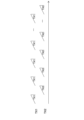
- chirp signals are transmitted so that the transmission timing of each chirp signal TX is equally spaced with respect to the burst interval TB.
- the burst interval TB is the interval between multiple chirp signals from the same antenna when the chirp signals multiplexed between the transmitting antennas are separated for each transmitting antenna.
- the first transmitting chirp signal TX1 from the first transmitting antenna 211A is transmitted at equal intervals with a timing of 0 [ ⁇ s]
- the second chirp signal TX2 from the second transmitting antenna 212A is transmitted at equal intervals with a timing of TB ⁇ 1/2 [ ⁇ s].
- the angular velocity ⁇ can be calculated using equation (1).
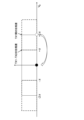
- Figure 9 shows the correction of phase difference due to velocity ambiguity.
- phase difference between the chirp signals TX1 and TX2 is ⁇ .
- phase correction speed wrap correction process
- phase correction speed wrap correction process
- Figure 10 shows the angle of arrival spectrum corresponding to (A) and (B) in Figure 9. Only when the phase difference between the chirp signals TX1 and TX2 is corrected, the main lobe of the angle of arrival spectrum (AoA (Angle of Arrival) spectrum) has a maximum value, and the ratio of the main lobe to the side lobe is also maximized.
- AoA Angle of Arrival
- MIMO speed phase correction and AoA can be performed for multiple possible speeds, and the speed candidate with the greater power can be determined as the true speed.
- Speed expansion makes it possible to detect the true speed even if the speed wraps around. Also, knowing the true speed makes it possible to prevent power drops, ghosting, false detection, etc.
- the velocity aliasing correction process detects the occurrence of aliasing, corrects the FFT results, and calculates the arrival angle spectrum, making it possible to obtain an accurate velocity. This process can determine the correct velocity when the received signal is a reflected signal from a target and has a uniquely determined arrival angle.
- the determination unit 225B determines whether or not an unwanted signal is present from the multiple arrival angle spectra generated by the aliasing correction unit 223B and the arrival angle information generation unit 224B.
- the unwanted signal is an interference signal transmitted from a transmission device other than the transmission device 210 (for example, a transmission device of an oncoming vehicle), and in this embodiment, parallel interference (constant interference, close interference) is assumed.
- parallel interference constant interference, close interference
- Figure 11 is a diagram showing a schematic diagram of a transmission signal, where (A) shows the transmission chirp signals TX1, TX2 and the reception signals RX1, RX2, (B) shows a state in which one pulse I1 of the parallel interference has entered, and (C) shows a state in which a signal I2 with synchronized timing has entered from the parallel interference.
- Parallel interference includes interference with other FMCW radars that have roughly the same frequency sweep timing.
- parallel interference is interference caused by the intrusion of a signal with roughly the same frequency gradient as the transmission chirp signals TX1 and TX2 transmitted from the transmitter 210.
- the unwanted signal also includes multipath, a phenomenon in which radar waves are reflected off the road surface, wall surfaces, etc., and received waves from the same object are detected via multiple paths.
- the determination unit 225B determines whether there is parallel interference and multipath interference (unwanted signals).
- the judgment unit 225B judges that no unwanted signal is present if there is only one arrival angle spectrum among the multiple arrival angle spectra in which the intensity of the second peak, which has the next highest reception intensity after the first peak, is equal to or lower than a predetermined intensity relative to the intensity of the first peak, among the multiple arrival angle spectra (first judgment); judges that an unwanted signal is present if there are multiple arrival angle spectra among the multiple arrival angle spectra in which the intensity of the second peak is equal to or lower than a predetermined intensity relative to the intensity of the first peak (second judgment); and judges that an unwanted signal is present if there is no arrival angle spectrum among the multiple arrival angle spectra in which the intensity of the second peak is equal to or lower than a predetermined intensity relative to the intensity of the first peak (third judgment).
- the received signal is normal. If there is no velocity fold number that correctly corrects the phase difference between chirp signals TX1 and TX2, or if there are multiple velocity fold numbers that correctly correct the phase difference, the received signal is determined to be a false signal caused by interference or a signal caused by unwanted reflection.
- Figure 12 is a diagram showing the aliasing correction process in the case of Figure 11 (A).
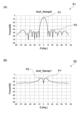
- Figure 13 shows the arrival angle spectrum when no unwanted signal is present, where (A) is the correct spectrum and (B) is the incorrect spectrum.
- "0" and " ⁇ " shown in FIG. 12 indicate the phase shift, and are expressed in units of, for example, radians.
- the first distance/speed signal D1 and the second distance/speed signal D2 have no phase shift
- the first angle-of-arrival spectrum S1 shown in FIG. 13(A) is the spectrum obtained when AoA is performed (Fourier transform processing is performed) on the first corrected signal H1 shown in FIG. 12
- the second angle-of-arrival spectrum S2 shown in FIG. 13(B) is the spectrum obtained when AoA is performed (Fourier transform processing is performed) on the second corrected signal H2 shown in FIG. 12.
- a correct spectrum is an arrival angle spectrum in which the second peak P2 is equal to or lower than a predetermined value relative to the intensity (dB) of the first peak P1.
- an incorrect spectrum is an arrival angle spectrum in which the second peak (P2) is not equal to or lower than a predetermined value relative to the intensity (dB) of the first peak P1.
- equal to or lower than a predetermined value means, for example, 30 dB lower than the reception intensity of the first peak P1, but of course it is not limited to 30 dB and may be 10 dB or 40 dB. It is also not limited to this and may be equal to or lower than half or one third of the reception intensity of the first peak P1.
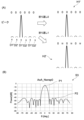
- Figure 14 shows the processing of the judgment processing unit 220B in the case of Figure 11 (B), (A) shows the aliasing correction processing, and (B) shows the third arrival angle spectrum S3.
- the third arrival angle spectrum S3 shown in FIG. 14(B) is a spectrum when the number of velocity folds is 0 and 1, and there is almost no change in shape.
- “almost no change” means that there is no change in peak intensity or spectrum shape (for example, the shapes are 60% or more identical).
- the third arrival angle spectrum S3 shown in FIG. 14(B) is in a state where a single pulse I1 has intruded, as shown in FIG. 11(B). For this reason, even if a velocity aliasing correction process is performed, there is almost no change in the shape of the spectrum (in other words, the intruding single pulse I1 has caused the peak intensity to increase in some places, and no change in the shape is observed even when the phase is rotated).
- the third arrival angle spectrum S3 in FIG. 14(B) has the same shape whether the number of velocity folds is 0 or 1, and there are multiple arrival angle spectra in which the intensity of the second peak P2 is equal to or lower than a predetermined value relative to the intensity of the first peak P1, and it is judged that an unwanted signal (single pulse I1) is present.
- Figure 15 shows the processing of the judgment processing unit 220B in the case of Figure 11 (C), (A) shows the aliasing correction processing, and (B) shows the fourth arrival angle spectrum S4.
- the phases of D1'' and D2'' do not match regardless of whether the number of velocity wraps is 0 or 1.
- the phases of D1'' and D2'' are always shifted by 1.1 regardless of the velocity wrap.
- the fourth arrival angle spectrum S4 shown in FIG. 15(B) is an erroneous spectrum in both cases where the number of velocity folds is 0 and 1, and its shape shows almost no change.
- almost no change means that the peak intensity and spectrum shape do not change (for example, the shapes are 60% or more identical), as described above.
- the fourth arrival angle spectrum S4 shown in FIG. 15(B) is in a state where the timing-synchronized signal I2 has entered as shown in FIG. 11(B). For this reason, even if a speed wraparound correction process is performed, there is almost no change in the shape of the spectrum (in other words, for example, when the timing-synchronized signal I2 enters from an oncoming vehicle, the phase of the timing-synchronized signal I2 and the phase of the transmission chirp signals TX1 and TX2 transmitted from the transmitter 210 are misaligned, so even if the phase is rotated, no change is observed).
- the fourth arrival angle spectrum S4 in FIG. 15(B) has the same shape (incorrect spectrum shape) whether the number of velocity wraparounds is 0 or 1, and since there is no arrival angle spectrum in which the intensity P2 of the second peak is equal to or less than a predetermined value relative to the intensity of the first peak P1, it is judged that an unwanted signal is present.
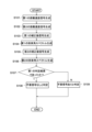
- Figure 16 is a flowchart showing the processing procedure for determining whether an unwanted signal is present in this embodiment. The following flowchart will mainly explain the case of Figure 11 (A).
- the conversion processing unit 222B performs Fourier transform processing on the first beat signal generated by the beat signal generating unit 221B based on the first transmitted chirp signal TX1 and the first reflected chirp signal RX1 to generate a first distance velocity signal D1 (step S101).
- the conversion processing unit 22B performs Fourier transform processing on the second beat signal generated by the beat signal generating unit 221B based on the second transmitted chirp signal TX2 and the second reflected chirp signal RX2 to generate a second distance velocity signal D2 (step S102).
- the folding correction unit 23B performs a correction process on the first distance-speed signal D1 and the second distance-speed signal D2 that corresponds to a speed folding count of 0 (i.e., does not correct the phase) to generate a first corrected signal H1 (step S103).
- the arrival angle information generating unit 24B performs AoA (executes Fourier transform processing) on the first corrected signal D1 to generate a first arrival angle spectrum S1 (step S104).
- the folding correction unit 23B performs a correction process (i.e., corrects the phase) on the first distance-speed signal D1 and the second distance-speed signal D2, which corresponds to one folding speed, and generates a second corrected signal H2 (step S105).
- a correction process i.e., corrects the phase
- the arrival angle information generating unit 24B performs AoA (executes Fourier transform processing) on the second corrected signal H2 to generate a second arrival angle spectrum S2 (step S106).
- the determination unit 25B compares the first arrival angle spectrum S1 with the second arrival angle spectrum S2, and determines whether the result is the first determination result described above (step S107).
- step S107 it is determined that no unwanted signal is present and that the object 300 is an actually existing target (step S108). That is, in the case of FIG. 11(A), step S107 is YES. If step S107 is NO, the second or third judgment result is obtained and it is determined that an unwanted signal due to parallel interference or multipath is present (step S109). That is, in the cases of FIG. 11(B) and (C), step S107 is NO, the second or third judgment result is obtained, and it is determined that an unwanted signal is present.
- the determination device 220 determines whether or not an unwanted signal is present using the arrival angle spectrum calculated to detect (estimate) the angle or speed (relative speed) of the object 300 relative to the receiving unit 220A (determination device 220, radar device 200).
- transmission chirp signals are transmitted from different transmitting antennas (first transmitting antenna 101A, second transmitting antenna 102A) by time division.
- transmission chirp signals may be transmitted from the same transmitting antenna by phase division.
- a process is executed to average the distance/rate signal D and the first corrected signal H obtained by performing zero velocity folding on the distance/rate signal D to generate a first averaged signal Av1. Also, a process is executed to average the distance/rate signal D and the second corrected signal H' obtained by performing one velocity folding on the distance/rate signal D to generate a second averaged signal Av2.
- the averaging referred to here is a process of averaging the phases of the distance/rate signal D and the first corrected signal H'. For example, if the phase of the first corrected signal H' corrected by velocity folding is shifted by + ⁇ from the phase of the distance/rate signal D, then by performing the averaging process, the phase of the first averaged signal Av1 will be shifted by + ⁇ /2 from the phase of the distance/rate signal D.
- AoA is performed on the first averaged signal Av1 in the same manner as in step S104 above, and AoA is performed on the second averaged signal Av2 in the same manner as in step S106 above.
- the unwanted signal shown in FIG. 11B is a signal by single-input multiple-output (SIMO), but of course, this is not limited to this, and for example, it may be a case where an oncoming vehicle uses MIMO and its signal enters. Even in this case, it is possible to determine whether or not an unwanted signal exists.
- the speed aliasing correction process phase correction
- the speed aliasing correction process may be performed on the first distance/speed signal D1.
- whether the spectrum is correct is determined based on the difference between the reception strength of the first peak P1 and the reception strength of the second peak P2, but of course this is not limited to this, and it may be determined based on whether the arrival angle spectra of each other have a predetermined matching rate (e.g., 60% or more) or more.
- a predetermined matching rate e.g. 60% or more
- the matching rate between multiple arrival angle spectra is below a predetermined value (corresponding to the diagram in this embodiment), it can be determined that no unwanted signal is present, and if the matching rate between multiple arrival angle spectra is not below a predetermined value, it can be determined that an unwanted signal is present. And, among the multiple arrival angle spectra determined to not contain an unwanted signal, if the difference between the reception intensity of the first peak P1 and the reception intensity of the second peak P2 is above a predetermined value as described above, it can be determined to be a correct spectrum.
- the speed wraparound correction process is performed 0 and 1 time, but it is not limited to this and may be performed 0 to 2 or more times.
- the phase correction range in this embodiment is expanded from - ⁇ to + ⁇ to -2 ⁇ to +2 ⁇ , but by further widening this phase correction range, the speed wraparound correction process (number of wraparounds) can be expanded to 2 or 3 times.
- FIG. 18 is a block diagram showing an example of the configuration of a vehicle control system 11, which is an example of a mobility device control system to which the present technology is applied.
- the vehicle control system 11 is provided in the vehicle 1 and performs processing related to the automated driving of the vehicle 1.
- This automated driving includes driving automation of levels 1 to 5, as well as remote driving and remote assistance of the vehicle 1 by a remote driver.
- the vehicle control system 11 includes a vehicle control ECU (Electronic Control Unit) 21, a communication unit 22, a map information storage unit 23, a location information acquisition unit 24, an external recognition sensor 25, an in-vehicle sensor 26, a vehicle sensor 27, a memory unit 28, a driving automation control unit 29, a DMS (Driver Monitoring System) 30, an HMI (Human Machine Interface) 31, and a vehicle control unit 32.
- vehicle control ECU Electronic Control Unit
- communication unit 22 includes a vehicle control ECU (Electronic Control Unit) 21, a communication unit 22, a map information storage unit 23, a location information acquisition unit 24, an external recognition sensor 25, an in-vehicle sensor 26, a vehicle sensor 27, a memory unit 28, a driving automation control unit 29, a DMS (Driver Monitoring System) 30, an HMI (Human Machine Interface) 31, and a vehicle control unit 32.
- the vehicle control ECU 21, communication unit 22, map information storage unit 23, position information acquisition unit 24, external recognition sensor 25, in-vehicle sensor 26, vehicle sensor 27, memory unit 28, driving automation control unit 29, DMS 30, HMI 31, and vehicle control unit 32 are connected to each other so as to be able to communicate with each other via a communication network 41.
- the communication network 41 is composed of an in-vehicle communication network or bus that complies with digital two-way communication standards such as CAN (Controller Area Network), LIN (Local Interconnect Network), LAN (Local Area Network), FlexRay (registered trademark), and Ethernet (registered trademark).
- the communication network 41 may be used differently depending on the type of data being transmitted.
- CAN may be applied to data related to vehicle control
- Ethernet may be applied to large-volume data.
- each part of the vehicle control system 11 may be directly connected without going through the communication network 41, using wireless communication intended for communication over relatively short distances, such as near field communication (NFC) or Bluetooth (registered trademark).
- NFC near field communication
- Bluetooth registered trademark
- the vehicle control ECU 21 is composed of various processors, such as a CPU (Central Processing Unit) and an MPU (Micro Processing Unit).
- the vehicle control ECU 21 controls all or part of the functions of the vehicle control system 11.
- the communication unit 22 communicates with various devices inside and outside the vehicle, other vehicles, servers, base stations, etc., and transmits and receives various types of data. At this time, the communication unit 22 can communicate using multiple communication methods.
- the communication unit 22 communicates with servers (hereinafter referred to as external servers) on an external network via base stations or access points using wireless communication methods such as 5G (fifth generation mobile communication system), LTE (Long Term Evolution), and DSRC (Dedicated Short Range Communications).
- the external network with which the communication unit 22 communicates is, for example, the Internet, a cloud network, or an operator-specific network.
- the communication method that the communication unit 22 uses with the external network is not particularly limited as long as it is a wireless communication method that allows digital two-way communication at a communication speed equal to or higher than a predetermined distance.
- the communication unit 22 can communicate with a terminal present in the vicinity of the vehicle using P2P (Peer To Peer) technology.
- the terminal present in the vicinity of the vehicle can be, for example, a terminal attached to a mobile object moving at a relatively slow speed, such as a pedestrian or a bicycle, a terminal installed at a fixed position in a store, or an MTC (Machine Type Communication) terminal.
- the communication unit 22 can also perform V2X communication.
- V2X communication refers to communication between the vehicle and others, such as vehicle-to-vehicle communication with other vehicles, vehicle-to-infrastructure communication with roadside devices, vehicle-to-home communication with a home, and vehicle-to-pedestrian communication with a terminal carried by a pedestrian, etc.
- the communication unit 22 can, for example, receive from the outside a program for updating the software that controls the operation of the vehicle control system 11 (Over the Air).
- the communication unit 22 can further receive map information, traffic information, information about the surroundings of the vehicle 1, etc. from the outside.
- the communication unit 22 can also transmit information about the vehicle 1 and information about the surroundings of the vehicle 1 to the outside.
- Information about the vehicle 1 that the communication unit 22 transmits to the outside includes, for example, data indicating the state of the vehicle 1, the recognition results by the recognition unit 73, etc.
- the communication unit 22 performs communication corresponding to a vehicle emergency notification system such as e-Call.
- the communication unit 22 receives electromagnetic waves transmitted by a road traffic information and communication system (VICS (Vehicle Information and Communication System) (registered trademark)) such as a radio beacon, optical beacon, or FM multiplex broadcasting.
- VICS Vehicle Information and Communication System
- the communication unit 22 can communicate with each device in the vehicle using, for example, wireless communication.
- the communication unit 22 can perform wireless communication with each device in the vehicle using a communication method that allows digital two-way communication at a communication speed equal to or higher than a predetermined speed via wireless communication, such as wireless LAN, Bluetooth, NFC, or WUSB (Wireless USB).
- the communication unit 22 can also communicate with each device in the vehicle using wired communication.
- the communication unit 22 can communicate with each device in the vehicle using wired communication via a cable connected to a connection terminal (not shown).
- the communication unit 22 can communicate with each device in the vehicle using a communication method that allows digital two-way communication at a communication speed equal to or higher than a predetermined speed via wired communication, such as USB (Universal Serial Bus), HDMI (High-Definition Multimedia Interface) (registered trademark), or MHL (Mobile High-definition Link).
- a communication method that allows digital two-way communication at a communication speed equal to or higher than a predetermined speed via wired communication, such as USB (Universal Serial Bus), HDMI (High-Definition Multimedia Interface) (registered trademark), or MHL (Mobile High-definition Link).
- the in-vehicle device refers to, for example, a device that is not connected to the communication network 41 inside the vehicle.
- examples of in-vehicle devices include mobile devices and wearable devices carried by users inside the vehicle, such as the driver, and information devices brought into the vehicle and temporarily installed.
- the map information storage unit 23 stores one or both of a map acquired from an external source and a map created by the vehicle 1.
- the map information storage unit 23 stores a three-dimensional high-precision map, a global map that is less accurate than a high-precision map and covers a wide area, etc.
- High-precision maps include, for example, dynamic maps, point cloud maps, and vector maps.
- a dynamic map is, for example, a map consisting of four layers of dynamic information, semi-dynamic information, semi-static information, and static information, and is provided to the vehicle 1 from an external server or the like.
- a point cloud map is a map made up of a point cloud (point cloud data).
- a vector map is, for example, a map that is adapted for driving automation by associating traffic information such as the positions of lanes and traffic lights with a point cloud map.
- the point cloud map and vector map may be provided, for example, from an external server, or may be created by the vehicle 1 based on sensing results from the camera 51, radar 52, LiDAR 53, etc. as a map for matching with a local map described below, and stored in the map information storage unit 23.
- map data of, for example, an area of several hundred meters square regarding the planned route along which the vehicle 1 will travel is acquired from the external server, etc., in order to reduce communication capacity.
- the location information acquisition unit 24 receives GNSS signals from Global Navigation Satellite System (GNSS) satellites and acquires location information of the vehicle 1.
- GNSS Global Navigation Satellite System
- the acquired location information is supplied to the driving automation control unit 29.
- the location information acquisition unit 24 is not limited to a method using GNSS signals, and may acquire location information using a beacon, for example.
- the external recognition sensor 25 includes various sensors used to recognize the situation outside the vehicle 1, and supplies sensor data from each sensor to each part of the vehicle control system 11.
- the type and number of sensors included in the external recognition sensor 25 are arbitrary.
- the external recognition sensor 25 includes a camera 51, a radar 52, a LiDAR (Light Detection and Ranging, Laser Imaging Detection and Ranging) 53, and an ultrasonic sensor 54.
- the external recognition sensor 25 may be configured to include one or more types of sensors among the camera 51, the radar 52, the LiDAR 53, and the ultrasonic sensor 54.
- the number of cameras 51, radars 52, LiDAR 53, and ultrasonic sensors 54 is not particularly limited as long as it is a number that can be realistically installed on the vehicle 1.
- the types of sensors included in the external recognition sensor 25 are not limited to this example, and the external recognition sensor 25 may include other types of sensors. Examples of the sensing areas of each sensor included in the external recognition sensor 25 will be described later.
- the imaging method of camera 51 is not particularly limited.
- cameras of various imaging methods such as a ToF (Time Of Flight) camera, a stereo camera, a monocular camera, and an infrared camera, which are imaging methods capable of distance measurement, can be applied to camera 51 as necessary.
- ToF Time Of Flight
- stereo camera stereo camera
- monocular camera stereo camera
- infrared camera infrared camera
- the present invention is not limited to this, and camera 51 may simply be used for acquiring photographic images, without regard to distance measurement.
- the external recognition sensor 25 can be equipped with an environmental sensor for detecting the environment relative to the vehicle 1.
- the environmental sensor is a sensor for detecting the environment such as the weather, climate, brightness, etc., and can include various sensors such as a raindrop sensor, a fog sensor, a sunlight sensor, a snow sensor, an illuminance sensor, etc.
- the external recognition sensor 25 includes a microphone that is used to detect sounds around the vehicle 1 and the location of sound sources.
- the in-vehicle sensor 26 includes various sensors for detecting information inside the vehicle, and supplies sensor data from each sensor to each part of the vehicle control system 11. There are no particular limitations on the types and number of the various sensors included in the in-vehicle sensor 26, so long as they are of the types and number that can be realistically installed in the vehicle 1.
- the in-vehicle sensor 26 may be equipped with one or more types of sensors including a camera, radar, a seating sensor, a steering wheel sensor, a microphone, and a biometric sensor.
- the camera equipped in the in-vehicle sensor 26 may be a camera using various imaging methods capable of measuring distances, such as a ToF camera, a stereo camera, a monocular camera, or an infrared camera. Without being limited to this, the camera equipped in the in-vehicle sensor 26 may be a camera simply for acquiring captured images, regardless of distance measurement.
- the biometric sensor equipped in the in-vehicle sensor 26 is provided, for example, on a seat, steering wheel, etc., and detects various types of biometric information of the user.
- the vehicle sensor 27 includes various sensors for detecting the state of the vehicle 1, and supplies sensor data from each sensor to each part of the vehicle control system 11. There are no particular limitations on the types and number of the various sensors included in the vehicle sensor 27, so long as they are of the types and number that can be realistically installed on the vehicle 1.
- the vehicle sensor 27 includes a speed sensor, an acceleration sensor, an angular velocity sensor (gyro sensor), and an inertial measurement unit (IMU) that integrates these.
- the vehicle sensor 27 includes a steering angle sensor that detects the steering angle of the steering wheel, a yaw rate sensor, an accelerator sensor that detects the amount of accelerator pedal operation, and a brake sensor that detects the amount of brake pedal operation.
- the vehicle sensor 27 includes a rotation sensor that detects the number of rotations of the engine or motor, an air pressure sensor that detects the air pressure of the tires, a slip ratio sensor that detects the slip ratio of the tires, and a wheel speed sensor that detects the rotation speed of the wheels.
- the vehicle sensor 27 includes a battery sensor that detects the remaining charge and temperature of the battery, and an impact sensor that detects external impacts.
- the memory unit 28 includes at least one of a non-volatile storage medium and a volatile storage medium, and stores data and programs.
- the memory unit 28 is used, for example, as an EEPROM (Electrically Erasable Programmable Read Only Memory) and a RAM (Random Access Memory), and the storage medium may be a magnetic storage device such as a hard disc drive (HDD), a semiconductor storage device, an optical storage device, or a magneto-optical storage device.
- the memory unit 28 stores various programs and data used by each part of the vehicle control system 11.
- the memory unit 28 includes an EDR (Event Data Recorder) and a DSSAD (Data Storage System for Automated Driving), and stores information about the vehicle 1 before and after an event such as an accident, and information acquired by the in-vehicle sensor 26.
- EDR Event Data Recorder
- DSSAD Data Storage System for Automated Driving
- the driving automation control unit 29 controls the driving automation function of the vehicle 1.
- the driving automation control unit 29 includes an analysis unit 61, an action planning unit 62, and an operation control unit 63.
- the analysis unit 61 performs analysis processing of the vehicle 1 and the surrounding conditions.
- the analysis unit 61 includes a self-position estimation unit 71, a sensor fusion unit 72, and a recognition unit 73.
- the self-position estimation unit 71 estimates the self-position of the vehicle 1 based on the sensor data from the external recognition sensor 25 and the high-precision map stored in the map information storage unit 23. For example, the self-position estimation unit 71 generates a local map based on the sensor data from the external recognition sensor 25, and estimates the self-position of the vehicle 1 by matching the local map with the high-precision map.
- the position of the vehicle 1 is based on, for example, the center of the rear wheel pair axle.
- the local map is, for example, a three-dimensional high-precision map or an occupancy grid map created using technology such as SLAM (Simultaneous Localization and Mapping).
- the three-dimensional high-precision map is, for example, the point cloud map described above.
- the occupancy grid map is a map in which the three-dimensional or two-dimensional space around the vehicle 1 is divided into grids of a predetermined size, and the occupancy state of objects is shown on a grid-by-grid basis.
- the occupancy state of objects is indicated, for example, by the presence or absence of an object and the probability of its existence.
- the local map is also used, for example, in detection processing and recognition processing of the situation outside the vehicle 1 by the recognition unit 73.
- the self-position estimation unit 71 may estimate the self-position of the vehicle 1 based on the position information acquired by the position information acquisition unit 24 and the sensor data from the vehicle sensor 27.
- the sensor fusion unit 72 performs sensor fusion processing to obtain information by combining multiple different types of sensor data (e.g., image data supplied from the camera 51 and sensor data supplied from the radar 52). Methods for combining different types of sensor data include compounding, integration, fusion, and association.
- the recognition unit 73 executes a detection process to detect the situation outside the vehicle 1, and a recognition process to recognize the situation outside the vehicle 1.
- the recognition unit 73 performs detection and recognition processing of the situation outside the vehicle 1 based on information from the external recognition sensor 25, information from the self-position estimation unit 71, information from the sensor fusion unit 72, etc.
- the recognition unit 73 performs detection processing and recognition processing of objects around the vehicle 1.
- Object detection processing is, for example, processing to detect the presence or absence, size, shape, position, movement, etc. of an object.
- Object recognition processing is, for example, processing to recognize attributes such as the type of object, and to identify a specific object.
- detection processing and recognition processing are not necessarily clearly separated, and there may be overlap.
- the recognition unit 73 detects objects around the vehicle 1 by performing clustering to classify a point cloud based on sensor data from the radar 52, the LiDAR 53, or the like into clusters of points. This allows the presence or absence, size, shape, and position of objects around the vehicle 1 to be detected.
- the recognition unit 73 detects the movement of objects around the vehicle 1 by performing tracking to follow the movement of clusters of point clouds classified by clustering. This allows the speed and direction of travel (movement vector) of objects around the vehicle 1 to be detected.
- the recognition unit 73 detects or recognizes vehicles, people, bicycles, obstacles, structures, roads, traffic lights, traffic signs, road markings, etc. based on image data supplied from the camera 51.
- the recognition unit 73 may also recognize the types of objects around the vehicle 1 by performing recognition processing such as semantic segmentation.
- the recognition unit 73 can perform recognition processing of traffic rules around the vehicle 1 based on the map stored in the map information storage unit 23, the result of self-location estimation by the self-location estimation unit 71, and the result of recognition of objects around the vehicle 1 by the recognition unit 73. Through this processing, the recognition unit 73 can recognize the positions and states of traffic lights, the contents of traffic signs and road markings, the contents of traffic regulations, and lanes on which travel is possible, etc.
- the recognition unit 73 can perform recognition processing of the environment around the vehicle 1.
- the surrounding environment that the recognition unit 73 recognizes may include weather, temperature, humidity, brightness, and road surface conditions.
- the behavior planning unit 62 creates a behavior plan for the vehicle 1. For example, the behavior planning unit 62 creates the behavior plan by performing route planning and route following processing.
- Route planning includes global path planning and local path planning.
- Global path planning involves planning a rough route from the start to the goal.
- Local path planning is also called trajectory planning, and involves generating a trajectory that allows safe and smooth progress in the vicinity of vehicle 1 on the planned route, taking into account the motion characteristics of vehicle 1.
- Path following is a process of planning operations for safely and accurately traveling along a route planned by a route plan within a planned time.
- the action planning unit 62 can, for example, calculate the target speed and target angular velocity of the vehicle 1 based on the results of this path following process.
- the operation control unit 63 controls the operation of the vehicle 1 to realize the action plan created by the action planning unit 62.
- the operation control unit 63 controls the steering control unit 81, the brake control unit 82, and the drive control unit 83 included in the vehicle control unit 32 described below, and performs lateral vehicle motion control and longitudinal vehicle motion control so that the vehicle 1 proceeds along the trajectory calculated by the trajectory plan.
- the operation control unit 63 performs control aimed at driving automation, such as driver assistance functions such as collision avoidance or impact mitigation, following driving, maintaining vehicle speed, collision warning for the vehicle itself, and lane departure warning for the vehicle itself, and driving without the operation of the driver or a remote driver.
- the DMS 30 performs processes such as authenticating the driver and recognizing the driver's state based on the sensor data from the in-vehicle sensors 26 and the input data input to the HMI 31 (described later).
- Examples of the driver's state to be recognized include physical condition, alertness, concentration, fatigue, line of sight, level of intoxication, driving operation, posture, etc.
- the DMS 30 may also perform authentication processing for users other than the driver and recognition processing for the status of the users.
- the DMS 30 may also perform recognition processing for the status inside the vehicle based on sensor data from the in-vehicle sensor 26. Examples of the status inside the vehicle that may be recognized include temperature, humidity, brightness, odor, etc.
- HMI31 inputs various data and instructions, and displays various data to the user.
- the HMI 31 is equipped with an input device that allows a person to input data.
- the HMI 31 generates input signals based on data and instructions input via the input device, and supplies the signals to each part of the vehicle control system 11.
- the HMI 31 is equipped with input devices such as a touch panel, buttons, switches, and levers. Without being limited to these, the HMI 31 may further be equipped with an input device that allows information to be input by a method other than manual operation, such as voice or gestures.
- the HMI 31 may use, as an input device, an externally connected device such as a remote control device that uses infrared or radio waves, or a mobile device or wearable device that supports the operation of the vehicle control system 11.
- the HMI 31 generates visual information, auditory information, and tactile information for the user or the outside of the vehicle.
- the HMI 31 also performs output control to control the output, output content, output timing, output method, etc. of each piece of generated information.
- the HMI 31 generates and outputs, as visual information, information indicated by images or light, such as an operation screen, vehicle 1 status display, warning display, and monitor image showing the situation around the vehicle 1.
- the HMI 31 also generates and outputs, as auditory information, information indicated by sounds, such as voice guidance, warning sounds, and warning messages.
- the HMI 31 also generates and outputs, as tactile information, information that is imparted to the user's sense of touch by force, vibration, movement, etc.
- the output device from which the HMI 31 outputs visual information may be, for example, a display device that presents visual information by displaying an image itself, or a projector device that presents visual information by projecting an image.
- the display device may be a device that displays visual information within the user's field of vision, such as a head-up display, a transmissive display, or a wearable device with an AR (Augmented Reality) function, in addition to a display device having a normal display.
- the HMI 31 may also use display devices such as a navigation device, instrument panel, CMS (Camera Monitoring System), electronic mirror, lamp, etc., provided in the vehicle 1 as output devices that output visual information.
- the output device through which the HMI 31 outputs auditory information can be, for example, an audio speaker, headphones, or earphones.
- Haptic elements using haptic technology can be used as an output device for the HMI 31 to output tactile information.
- Haptic elements are provided on parts that the user touches, such as the steering wheel and the seat.
- the vehicle control unit 32 controls each part of the vehicle 1.
- the vehicle control unit 32 includes a steering control unit 81, a brake control unit 82, a drive control unit 83, a body control unit 84, a light control unit 85, and a horn control unit 86.
- the steering control unit 81 detects and controls the state of the steering system of the vehicle 1.
- the steering system includes, for example, a steering mechanism including a steering wheel, an electric power steering, etc.
- the steering control unit 81 includes, for example, a steering ECU that controls the steering system, an actuator that drives the steering system, etc.
- the brake control unit 82 detects and controls the state of the brake system of the vehicle 1.
- the brake system includes, for example, a brake mechanism including a brake pedal, an ABS (Antilock Brake System), a regenerative brake mechanism, etc.
- the brake control unit 82 includes, for example, a brake ECU that controls the brake system, and an actuator that drives the brake system.
- the drive control unit 83 detects and controls the state of the drive system of the vehicle 1.
- the drive system includes, for example, an accelerator pedal, a drive force generating device for generating drive force such as an internal combustion engine or a drive motor, and a drive force transmission mechanism for transmitting the drive force to the wheels.
- the drive control unit 83 includes, for example, a drive ECU for controlling the drive system, and an actuator for driving the drive system.
- the body system control unit 84 detects and controls the state of the body system of the vehicle 1.
- the body system includes, for example, a keyless entry system, a smart key system, a power window device, a power seat, an air conditioning system, an airbag, a seat belt, a shift lever, etc.
- the body system control unit 84 includes, for example, a body system ECU that controls the body system, an actuator that drives the body system, etc.
- the light control unit 85 detects and controls the state of various lights of the vehicle 1. Examples of lights to be controlled include headlights, backlights, fog lights, turn signals, brake lights, projection, and bumper displays.
- the light control unit 85 includes a light ECU that controls the lights, an actuator that drives the lights, and the like.
- the horn control unit 86 detects and controls the state of the car horn of the vehicle 1.
- the horn control unit 86 includes, for example, a horn ECU that controls the car horn, an actuator that drives the car horn, etc.
- FIG. 19 is a diagram showing an example of a sensing area by the camera 51, radar 52, LiDAR 53, ultrasonic sensor 54, etc. of the external recognition sensor 25 in FIG. 18. Note that FIG. 19 shows a schematic view of the vehicle 1 as seen from above, with the left end side being the front end of the vehicle 1 and the right end side being the rear end of the vehicle 1.
- Sensing area 101F and sensing area 101B show examples of sensing areas of ultrasonic sensors 54. Sensing area 101F covers the periphery of the front end of vehicle 1 with multiple ultrasonic sensors 54. Sensing area 101B covers the periphery of the rear end of vehicle 1 with multiple ultrasonic sensors 54.
- sensing results in sensing area 101F and sensing area 101B are used, for example, for parking assistance for vehicle 1.
- Sensing area 102F to sensing area 102B show examples of sensing areas of a short-range or medium-range radar 52. Sensing area 102F covers a position farther in front of the vehicle 1 than sensing area 101F. Sensing area 102B covers a position farther in the rear of the vehicle 1 than sensing area 101B. Sensing area 102L covers the rear periphery of the left side of the vehicle 1. Sensing area 102R covers the rear periphery of the right side of the vehicle 1.
- the sensing results in sensing area 102F are used, for example, to detect vehicles, pedestrians, etc., that are in front of vehicle 1.
- the sensing results in sensing area 102B are used, for example, for collision prevention functions behind vehicle 1.
- the sensing results in sensing area 102L and sensing area 102R are used, for example, to detect objects in blind spots to the sides of vehicle 1.
- Sensing area 103F to sensing area 103B show examples of sensing areas by camera 51. Sensing area 103F covers a position farther in front of vehicle 1 than sensing area 102F. Sensing area 103B covers a position farther in the rear of vehicle 1 than sensing area 102B. Sensing area 103L covers the periphery of the left side of vehicle 1. Sensing area 103R covers the periphery of the right side of vehicle 1.
- the sensing results in sensing area 103F can be used, for example, for recognizing traffic lights and traffic signs, lane departure prevention support systems, and automatic headlight control systems.
- the sensing results in sensing area 103B can be used, for example, for parking assistance and surround view systems.
- the sensing results in sensing area 103L and sensing area 103R can be used, for example, for surround view systems.
- Sensing area 104 shows an example of the sensing area of LiDAR 53. Sensing area 104 covers a position farther in front of vehicle 1 than sensing area 103F. On the other hand, sensing area 104 has a narrower range in the left-right direction than sensing area 103F.
- the sensing results in the sensing area 104 are used, for example, to detect objects such as surrounding vehicles.
- a sensing area 105 shows an example of a sensing area of a long-range radar 52 .
- the sensing area 105 covers a position farther in front of the vehicle 1 than the sensing area 104.
- the sensing area 105 has a narrower range in the left-right direction than the sensing area 104.
- the sensing results in the sensing area 105 are used, for example, for ACC (Adaptive Cruise Control), emergency braking, collision avoidance, etc.
- ACC Adaptive Cruise Control
- emergency braking braking
- collision avoidance etc.
- the sensing areas of the cameras 51, radar 52, LiDAR 53, and ultrasonic sensors 54 included in the external recognition sensor 25 may have various configurations other than those shown in FIG. 2. Specifically, the ultrasonic sensor 54 may also sense the sides of the vehicle 1, and the LiDAR 53 may sense the rear of the vehicle 1.
- the installation positions of the sensors are not limited to the examples described above. The number of sensors may be one or more.
- the radar device 200 of the present disclosure may be applied to the radar 52 of the external recognition sensor 25.
- the presence or absence of generation of unwanted waves such as radio wave interference may be determined, and if it is determined that unwanted waves are generated, a notice may be sent to the user of the vehicle 1 that the radar device 200 may not operate properly.
- the on-board control system 11 may restrict some or all of the driving automation functions that operate based on the sensing results of the radar device 200.
- the present disclosure may have the following configurations.
- a receiving unit that receives a first reflected chirp signal that is a first transmission chirp signal that is transmitted by a transmitting device toward an object and reflected by the object, and a second reflected chirp signal that is a second transmission chirp signal that is irradiated by the transmitting device at a time different from the time when the first transmission chirp signal is irradiated and reflected by the object; a determination processing unit that generates a plurality of angle-of-arrival spectra based on a plurality of corrected signals obtained by performing a plurality of velocity aliasing correction processes on the first reflected chirp signal and the second reflected chirp signal received by the receiving unit, and compares the plurality of angle-of-arrival spectra with each other to determine whether or not an unwanted signal has been received.
- the determination processing unit includes a beat signal generating unit that generates a first beat signal based on the first transmitted chirp signal and the first reflected chirp signal, and generates a second beat signal based on the second transmitted chirp signal and the second reflected chirp signal.
- the determination processing unit has a conversion processing unit that performs Fourier transform processing based on the first reflected chirp signal to generate a first distance velocity signal including a first distance signal related to the distance to the object and a first velocity signal related to the velocity of the object, and performs Fourier transform processing based on the second reflected chirp signal to generate a second distance velocity signal including a second distance signal related to the distance to the object and a second velocity signal related to the velocity of the object.
- the determination device described in (1) or (2) above.
- the determination processing unit The determination device according to any one of (1) to (3), further comprising a determination unit that determines that no unnecessary signal is present when there is only one arrival angle spectrum among the multiple arrival angle spectra in which the intensity of a second peak having the next highest reception intensity after a first peak is equal to or less than a predetermined intensity relative to the intensity of a first peak at which the reception intensity for the arrival angle of the first reflected chirp signal and the second reflected chirp signal is maximum, and determines that the unnecessary signal is present when there are multiple arrival angle spectra among the multiple arrival angle spectra in which the intensity of the second peak is equal to or less than a predetermined intensity relative to the intensity of the first peak and when there is no arrival angle spectrum among the multiple arrival angle spectra in which the intensity of the second peak is equal to or less than the predetermined intensity relative to the intensity of the first peak.
- the determination device according to any one of (1) to (4), wherein the unnecessary signal is an interference signal transmitted from a transmitting device other than the transmitting device.
- the unnecessary signal is a signal that is the first transmission chirp signal transmitted from the transmitting device, reflected by the object and also reflected by another object different from the object.
- a method for determining whether or not an unwanted signal is received comprising: generating a plurality of angle-of-arrival spectra based on a plurality of corrected signals obtained by performing a plurality of velocity aliasing correction processes on the received first reflected chirp signal and the second reflected chirp signal; and comparing the plurality of angle-of-arrival spectra with each other.
- a transmitting device that transmits a first transmission chirp signal and a second transmission chirp signal that is irradiated at a time different from the time when the first transmission chirp signal is irradiated toward an object; a receiving unit that receives a first reflected chirp signal resulting from the first transmitted chirp signal being reflected by the object, and a second reflected chirp signal resulting from the second transmitted chirp signal being reflected by the object; a determination processing unit that generates a plurality of angle-of-arrival spectra based on a plurality of corrected signals obtained by performing a plurality of velocity aliasing correction processes on the first reflected chirp signal and the second reflected chirp signal received by the receiving unit, and compares the plurality of angle-of-arrival spectra to determine whether or not an unwanted signal has been received.
- the transmitting device includes a first transmitting antenna that transmits the first transmitting chirp signal and a second transmitting antenna that transmits the second transmitting chirp signal.
- the transmitting device includes a transmitting antenna that transmits the first transmission chirp signal and the second transmission chirp signal in a time division manner.
- the transmitting device includes a transmitting antenna that transmits the first transmitting chirp signal and the second transmitting chirp signal by phase division.
- Radar device 210 Transmitting device 210A: Transmitting antenna array 210B: Signal generating unit 220: Determination device 220A: Receiving antenna array 220B: Determination processing unit 221B: Beat signal generating unit 222B: Conversion processing unit 223B: Alias correction unit 224B: Arrival angle information generating unit 225B: Determination unit 300: Object
Landscapes
- Engineering & Computer Science (AREA)
- Radar, Positioning & Navigation (AREA)
- Remote Sensing (AREA)
- Computer Networks & Wireless Communication (AREA)
- Physics & Mathematics (AREA)
- General Physics & Mathematics (AREA)
- Radar Systems Or Details Thereof (AREA)
Abstract
【課題】電波干渉があった場合でもノイズフロアを上昇させず、また電波干渉のための特別なモードを設けることなく電波干渉の有無を判定する判定装置、判定方法、判定プログラム及びレーダ装置を提供する。 【解決手段】本技術の一形態に係る判定装置は、受信部と、判定処理部とを具備する。受信部は、送信装置によって物体に向けて送信された第1の送信チャープ信号が物体に反射した第1の反射チャープ信号と、第1の送信チャープ信号が照射される時間とは異なる時間に送信装置によって照射される第2の送信チャープ信号が物体に反射した第2の反射チャープ信号と、を受信する。判定処理部は、第1の反射チャープ信号及び第2の反射チャープ信号に対して複数の速度折り返し補正処理が実施された複数の補正後信号に基づいて生成された複数の到来角スペクトル同士を比較し不要信号の受信の有無を判定する。
Description
本技術は、周波数変調連続波(FMCW、Frequency Modulated
Continuous Wave)レーダの電波干渉などの不要波の発生の有無を判定するための判定装置、判定方法、判定プログラム及びレーダ装置に関する。
Continuous Wave)レーダの電波干渉などの不要波の発生の有無を判定するための判定装置、判定方法、判定プログラム及びレーダ装置に関する。
多入力多出力(MIMO、Multi Input Multi Output)レーダにおいて、複数の送信アンテナが、チャープ信号をバーストと呼ばれる群単位で送信する。受信アンテナは、反射されたチャープ信号を受信する。受信された信号は、ダウンコンバートされ、ディジタル化され、次いで、レーダ前方の複数のオブジェクトの距離、速度、及び到来角を得るために処理される。チャープ信号は、経時的に周波数が線形に変化する信号である。
しかしながら、レーダ前方の複数のオブジェクトの距離、速度、及び到来角を検出する際、例えば、対向車に搭載されたレーダシステム等との間で電波干渉を起こす場合がある。電波干渉による誤ピークを低減するため符号化された送信波を用いた場合、誤ピークを低減することはできるが、ノイズフロアが上昇してしまうという問題があった。
その問題に対して、特許文献1には、レーダセンサから取得された信号である非対策信号に対して、電波干渉の影響を抑制する干渉除去処理を施して対策信号を生成し、設定されている動作モードが干渉モードであれば対策信号を用い、動作モードが通常モードであれば非対策信号を用いて、周波数解析処理を実行し、電波干渉の有無を判断するレーダシステム1について記載されている。
しかしながら、特許文献1では電波干渉のために別途特別なモードを設ける必要があり、効率が悪いという問題があった。
以上のような事情に鑑み、本技術の目的は、電波干渉があった場合でもノイズフロアを上昇させず、また電波干渉のための特別なモードを設けることなく電波干渉の有無を判定する判定装置、判定方法、判定プログラム及びレーダ装置を提供することにある。
本技術の一形態に係る判定装置は、受信部と、判定処理部とを具備する。
上記受信部は、送信装置によって物体に向けて送信された第1の送信チャープ信号が上記物体に反射した第1の反射チャープ信号と、上記第1の送信チャープ信号が照射される時間とは異なる時間に上記送信装置によって照射される第2の送信チャープ信号が上記物体に反射した第2の反射チャープ信号と、を受信する。
上記判定処理部は、上記受信部により受信した上記第1の反射チャープ信号及び上記第2の反射チャープ信号に対して複数の速度折り返し補正処理が実施された複数の補正後信号に基づいて複数の到来角スペクトルを生成し、上記複数の到来角スペクトル同士を比較し不要信号の受信の有無を判定する。
上記受信部は、送信装置によって物体に向けて送信された第1の送信チャープ信号が上記物体に反射した第1の反射チャープ信号と、上記第1の送信チャープ信号が照射される時間とは異なる時間に上記送信装置によって照射される第2の送信チャープ信号が上記物体に反射した第2の反射チャープ信号と、を受信する。
上記判定処理部は、上記受信部により受信した上記第1の反射チャープ信号及び上記第2の反射チャープ信号に対して複数の速度折り返し補正処理が実施された複数の補正後信号に基づいて複数の到来角スペクトルを生成し、上記複数の到来角スペクトル同士を比較し不要信号の受信の有無を判定する。
本実施形態によれば、物体に反射した第1の反射チャープ信号と、第1の反射チャープ信号とは異なる第2の反射チャープ信号と、を受信し、第1の反射チャープ信号及び第2の反射チャープ信号に対して複数の速度折り返し補正処理が実施された複数の補正後信号に基づいて複数の到来角スペクトルを生成し、複数の到来角スペクトル同士を比較することで不要信号の受信の有無を判定する。つまり、電波干渉としての不要信号の有無を上記複数の到来角スペクトル同士を比較することで、判定できる。これにより、電波干渉があった場合でもノイズフロアを上昇させず、また電波干渉のための特別なモードを設けることなく電波干渉の有無を判定することができる。
上記判定処理部は、上記第1の送信チャープ信号と上記第1の反射チャープ信号とに基づいて第1のビート信号を生成し、上記第2の送信チャープ信号と上記第2の反射チャープ信号とに基づいて第2のビート信号を生成するビート信号生成部を有してもよい。
上記判定処理部は、上記第1の反射チャープ信号に基づいてフーリエ変換処理を実行して上記物体までの距離に関する第1の距離信号及び上記物体の速度に関する第1の速度信号を含む第1の距離速度信号と、上記第2の反射チャープ信号に基づいて上記フーリエ変換処理を実行して上記物体までの距離に関する第2の距離信号及び上記物体の速度に関する第2の速度信号を含む第2の距離速度信号とを生成する変換処理部を有してもよい。
上記判定処理部は、上記複数の到来角スペクトルのうち、上記第1の反射チャープ信号及び上記第2の反射チャープ信号の到来角度に対する受信強度が最大となる第1のピークの強度に対して上記第1のピークの次に上記受信強度が大きい第2のピークの強度が所定以下である到来角スペクトルが1つのみ存在する場合に、不要信号が存在しないと判定し、上記複数の到来角スペクトルのうち、上記第1のピークの強度に対して上記第2のピークの強度が所定以下である到来角スペクトルが複数存在する場合及び上記複数の到来角スペクトルにおいて上記第1のピークの強度に対して上記第2のピークの強度が所定以下である到来角スペクトルが存在しない場合に、上記不要信号が存在すると判定する判定部を有してもよい。
上記不要信号は、上記送信装置とは異なる他の送信装置から送信された干渉信号であってもよい。
上記不要信号は、上記送信装置から送信された上記第1の送信チャープ信号が上記物体に反射するとともに、上記物体とは異なる他の物体にも反射した信号であってもよい。
本技術の一形態に係る判定方法は、
送信装置によって物体に向けて送信された第1の送信チャープ信号が上記物体に反射した第1の反射チャープ信号と、上記第1の送信チャープ信号それぞれが照射される時間とは異なる時間に上記送信装置によって照射される第2の送信チャープ信号が上記物体に反射した第2の反射チャープ信号と、を受信し、
受信した上記第1の反射チャープ信号及び上記第2の反射チャープ信号に対して複数の速度折り返し補正処理が実施された複数の補正後信号に基づいて複数の到来角スペクトルを生成し、上記複数の到来角スペクトル同士を比較し不要信号の受信の有無を判定する。
送信装置によって物体に向けて送信された第1の送信チャープ信号が上記物体に反射した第1の反射チャープ信号と、上記第1の送信チャープ信号それぞれが照射される時間とは異なる時間に上記送信装置によって照射される第2の送信チャープ信号が上記物体に反射した第2の反射チャープ信号と、を受信し、
受信した上記第1の反射チャープ信号及び上記第2の反射チャープ信号に対して複数の速度折り返し補正処理が実施された複数の補正後信号に基づいて複数の到来角スペクトルを生成し、上記複数の到来角スペクトル同士を比較し不要信号の受信の有無を判定する。
本技術の一形態に係る判定プログラムは、
送信装置によって物体に向けて送信された第1の送信チャープ信号が上記物体に反射した第1の反射チャープ信号と、上記第1の送信チャープ信号それぞれが照射される時間とは異なる時間に上記送信装置によって照射される第2の送信チャープ信号が上記物体に反射した第2の反射チャープ信号と、を受信するステップと、
受信した上記第1の反射チャープ信号及び上記第2の反射チャープ信号に対して複数の速度折り返し補正処理が実施された複数の補正後信号に基づいて複数の到来角スペクトルを生成し、上記複数の到来角スペクトル同士を比較し不要信号の受信の有無を判定するステップと、
を実行させる。
送信装置によって物体に向けて送信された第1の送信チャープ信号が上記物体に反射した第1の反射チャープ信号と、上記第1の送信チャープ信号それぞれが照射される時間とは異なる時間に上記送信装置によって照射される第2の送信チャープ信号が上記物体に反射した第2の反射チャープ信号と、を受信するステップと、
受信した上記第1の反射チャープ信号及び上記第2の反射チャープ信号に対して複数の速度折り返し補正処理が実施された複数の補正後信号に基づいて複数の到来角スペクトルを生成し、上記複数の到来角スペクトル同士を比較し不要信号の受信の有無を判定するステップと、
を実行させる。
本技術の一形態に係るレーダ装置は、送信装置と、判定装置と、を具備する。
上記送信装置は、第1の送信チャープ信号と、上記第1の送信チャープ信号それぞれが照射される時間とは異なる時間に照射される第2の送信チャープ信号と、を物体に向けて送信する。
上記判定装置は、受信部と、判定処理部とを有し、
上記受信部は、送信装置によって物体に向けて送信された第1の送信チャープ信号が上記物体に反射した第1の反射チャープ信号と、上記第1の送信チャープ信号が照射される時間とは異なる時間に上記送信装置によって照射される第2の送信チャープ信号が上記物体に反射した第2の反射チャープ信号と、を受信する。
上記判定処理部は、上記受信部により受信した上記第1の反射チャープ信号及び上記第2の反射チャープ信号に対して複数の速度折り返し補正処理が実施された複数の補正後信号に基づいて複数の到来角スペクトルを生成し、上記複数の到来角スペクトル同士を比較し不要信号の受信の有無を判定する。
上記送信装置は、第1の送信チャープ信号と、上記第1の送信チャープ信号それぞれが照射される時間とは異なる時間に照射される第2の送信チャープ信号と、を物体に向けて送信する。
上記判定装置は、受信部と、判定処理部とを有し、
上記受信部は、送信装置によって物体に向けて送信された第1の送信チャープ信号が上記物体に反射した第1の反射チャープ信号と、上記第1の送信チャープ信号が照射される時間とは異なる時間に上記送信装置によって照射される第2の送信チャープ信号が上記物体に反射した第2の反射チャープ信号と、を受信する。
上記判定処理部は、上記受信部により受信した上記第1の反射チャープ信号及び上記第2の反射チャープ信号に対して複数の速度折り返し補正処理が実施された複数の補正後信号に基づいて複数の到来角スペクトルを生成し、上記複数の到来角スペクトル同士を比較し不要信号の受信の有無を判定する。
上記送信装置は、上記第1の送信チャープ信号を送信する第1の送信アンテナと、上記第2の送信チャープ信号を送信する第2の送信アンテナと、を含んでもよい。
上記送信装置は、上記第1の送信チャープ信号と上記第2の送信チャープ信号とを時分割にて送信する送信アンテナを含んでもよい。
上記送信装置は、上記第1の送信チャープ信号と上記第2の送信チャープ信号とを位相分割にて送信する送信アンテナを含んでもよい。
以下、本技術に係る実施形態を、図面を参照しながら説明する。
<本実施形態>
[レーダ装置]
図1は、本技術の実施形態において使用されるレーダ装置200の構成を示すブロック図である。レーダ装置200は、送信装置210と、判定装置220とを備える。送信装置210は、送信アンテナアレイ210Aと、信号生成部210Bとを有する。以下、各装置の構成について説明する。
[レーダ装置]
図1は、本技術の実施形態において使用されるレーダ装置200の構成を示すブロック図である。レーダ装置200は、送信装置210と、判定装置220とを備える。送信装置210は、送信アンテナアレイ210Aと、信号生成部210Bとを有する。以下、各装置の構成について説明する。
送信アンテナアレイ210Aは、複数のチャープ信号をそれぞれ送信する複数の送信アンテナを含む。送信アンテナアレイ210A及び受信アンテナアレイ220Aは、水平MIMOまたは垂直MIMOを構成する。ここで、受信アンテナアレイ220Aとは、物体300で反射された複数のチャープ信号を受信する複数の受信アンテナを含む。
図2は、水平MIMOの概念を模式的に示す。図3は、垂直MIMOの概念を模式的に示す。
上述したMIMOとは、複数(本例では8本)の受信アンテナに対して複数(本例では2本)の送信アンテナ(第1の送信アンテナ211A、第2の送信アンテナ212A)を空間的にずらして配置することで、仮想的に開口長(≒アンテナの受信面積)を増やす手法である。複数の送信アンテナを水平方向にずらして配置すると、水平方向の解像度が向上する(図2参照)。VA1は、仮想アレイであり、送信アンテナおよび受信アンテナの様々な組み合わせを表す。仮想アレイについてより詳しくは、複数の送信アンテナと複数の受信アンテナとを含むMIMOを数学的には等価なアンテナアレイである仮想SIMO(Sigle input Multiple output、単一入力多重出力)とみなし、(送信アンテナの個数×受信アンテナの個数)個の受信アンテナおよび1個の送信アンテナが存在しているとするものである。複数の送信アンテナを垂直方向にずらして配置すると、水平方向に加えて垂直方向の検出が可能となる(図3参照)。またVA2もVA1と同様に仮想アレイであり、送信アンテナおよび受信アンテナの様々な組み合わせを表す。
信号生成部210Bは、上述した送信アンテナアレイ210Aから送信する複数のチャープ信号を生成する機能を有する。信号生成部210Bは、第1のチャープ信号生成部211Bと、第2のチャープ信号生成部212Bと、タイミング制御部213Bと、第1の記憶部214Bとを有する。第1の記憶部214Bは、半導体メモリ、ハードディスク等の情報記憶装置である。第1の記憶部214Bには、信号生成部210Bを動作させるためのプログラムが格納される。
第1のチャープ信号生成部211Bは、上述した第1の送信アンテナ211Aから送信される第1の送信チャープ信号TX1を生成し、第2のチャープ信号生成部212Bは、上述した第2の送信アンテナ212Aから送信される第2の送信チャープ信号TX2を生成する。ここで、生成するとは、チャープ信号を単に生成するのみではなく、チャープ信号を送信することも意味する。また第1のチャープ信号生成部211Bは、送信した第1の送信チャープ信号TX1を判定処理部220Bにも送信する。これにより、後述するビート信号を生成することができる。第2のチャープ信号生成部212Bも第1のチャープ信号生成部211Bと同様に送信した第2の送信チャープ信号TX2を判定処理部220Bに送信する。
タイミング制御部213Bは、第1の送信チャープ信号TX1及び第2の送信チャープ信号TX2を外部(物体300)に向けて生成(送信)するタイミングを制御する。MIMOレーダを実現する場合、チャープ信号の送信方法として、一般的に時分割多重(TDM(Time Division Multiplexing)-MIMOが用いられることが多い。図4は、TDM-MIMOの概念を模式的に示す。
TDM-MIMOはMIMOを形成する送信アンテナから送信するチャープ信号を、送信アンテナの数だけ時分割に送信する。例えば、2本の送信アンテナのMIMOでは、2本の送信アンテナは、送信チャープ信号TX1,TX2を交互に送信する。ここで、2本の送信アンテナ(第1の送信アンテナ211A、第2の送信アンテナ212A)からの第1の送信チャープ信号TX1,第2の送信チャープ信号TX2の送信タイミングには時間的なずれがある。よって、対象物が速度を持つ場合(例えば対向車)、第1の送信アンテナ211Aから送信される第1の送信チャープ信号TX1により形成する受信信号(後述する第1の反射チャープ信号RX1)と、第2の送信アンテナ212Aから送信される第2の送信チャープ信号TX2により形成する受信信号(後述する第2の反射チャープ信号RX2)とには、速度と時間のずれに起因する位相のずれが生じる。この位相のずれを補正することにより、後述するように物体300と受信部220A(判定装置220、レーダ装置200)との距離、速度(または相対速度)または受信部220A(判定装置220、レーダ装置200)に対する物体300の到来角を算出することができる。
またタイミング制御部213Bは、第1の送信チャープ信号TX1及び第2の送信チャープ信号TX2を判定処理部220Bに向けて生成(送信)するタイミングも制御してもよい。つまり、例えばタイミング制御部213Bは、第1の送信チャープ信号TX1および第2の送信チャープ信号TX2を外部へ送信するとともにビート信号生成部221Bに送信してもよい。ビート信号生成部221Bは、例えば信号生成部210Bから送信されるタイミングによって第1の送信チャープ信号TX1か第2の送信チャープ信号TX2かを判断することができる。
判定装置220は、受信アンテナアレイ(受信部)220Aと、判定処理部220Bとを有する。受信アンテナアレイ220Aは、上述したように、第1の送信チャープ信号TX1が物体300に反射した第1の反射チャープ信号RX1と、第2の送信チャープ信号TX2が物体300に反射した第2の反射チャープ信号RX2と、を受信する。受信アンテナアレイ220Aは、本実施形態では、8本の受信アンテナを含むが、もちろん8本に限られず、例えば10本であってもよい。
判定処理部220Bは、送信チャープ信号が物体300に反射した反射チャープ信号に不要信号が存在するかどうかを判定する機能を有する。判定処理部220Bは、ビート信号生成部221Bと、変換処理部222Bと、折り返し補正部223Bと、到来角情報生成部224Bと、判定部225Bと、第2の記憶部226Bとを有する。第2の記憶部226Bは、半導体メモリ、ハードディスク等の情報記憶装置である。第2の記憶部226Bには、判定処理部220Bを動作させるためのプログラムが格納される。
ビート信号生成部221Bは、反射チャープ信号と第1のチャープ信号生成部211Bおよび第2のチャープ信号生成部212Bから送信された送信チャープ信号とに基づいて、ビート信号を生成する。ビート信号とは、反射チャープ信号と送信チャープ信号とを混合して、反射チャープ信号と送信チャープ信号との周波数の差分を周波数成分とする信号である。ビート信号は、IF(Intermediate Frequency 中間周波数)信号とも呼ばれる。つまり、本実施形態では、ビート信号生成部221Bは、第1のチャープ信号生成部211Bから送信された第1の送信チャープ信号TX1と第1の反射チャープ信号RX1とを混合して第1のビート信号IF1を生成し、第2のチャープ信号生成部212Bから送信された第2の送信チャープ信号TX2と第2の反射チャープ信号RX2とを混合して第2のビート信号IF2を生成する。
変換処理部222Bは、反射チャープ信号に基づいて、距離軸と速度軸のフーリエ変換処理(高速フーリエ変換処理(FFT、Fast Fourier transform)または離散フーリエ変換処理(DFT、Discrete Fourier Transform))を実行し、距離速度信号を生成する。距離速度信号とは、受信部220A(判定装置220)から物体300までの距離に関する距離情報及び物体の速度(または相対速度)に関する速度情報を含む。距離速度信号は、例えばX軸方向を距離ビン、X軸方向と直交するY軸方向を速度ビン、X軸、Y軸と直交するZ軸方向を信号強度としたグラフであらわされる。つまり、物体300までの距離及び物体300の速度(または相対速度)については、距離速度信号の信号強度に基づいて、算出される。
本実施形態では、変換処理部222Bは、第1のビート信号IF1に基づいてフーリエ変換処理を実行し、受信部220A(判定装置220、レーダ装置200)から物体300までの距離に関する第1の距離情報及び物体2の速度(または相対速度)に関する第1の速度情報を含む第1の距離速度信号D1と、第2のビート信号IF2に基づいてフーリエ変換処理を実行し、受信部220A(判定装置220、レーダ装置200)から物体2までの距離に関する第2の距離情報及び物体2の速度(または相対速度)に関する第2の速度情報を含む第2の距離速度信号D2と、を生成する。
折り返し補正部223Bは、距離速度信号に対して速度折り返し補正処理を実施する処理を行う。本実施形態では、折り返し補正部223Bは、第1の距離速度信号D1および第2の距離速度信号D2に対して速度折り返し回数が0回に相当する補正処理を実施し仮想アレイ化した第1の補正後信号H1を生成する。また折り返し補正部223Bは、第1の距離速度信号D1および第2の距離速度信号D2対して1回の速度折り返し回数が1回に相当する補正処理を実施し仮想アレイ化した第2の補正後信号H2を生成する。速度折り返し補正処理については後述する。
また到来角情報生成部224Bは、第1の補正後信号H1に対してフーリエ変換処理を実行して到来角スペクトルS1を生成する。さらに到来角情報生成部224Bは、第2の補正後信号H2に対してフーリエ変換処理を実行して到来角スペクトルS2を生成する。
ここで、速度折り返し補正処理および到来角情報生成部224の処理の処理手順について説明する。図5は、TDM-MIMOの速度位相誤差の概念を模式的に示し、図6は、TDM-MIMOの速度位相誤差補正の概念を模式的に示す。また図7は、速度曖昧性による速度位相補正の限界の概念を模式的に示す。
例えば対象物の速度は、TDM-MIMOにおいて複数の送信アンテナ間で多重されたチャープ信号を送信アンテナ毎に分離した後のチャープ信号TX1、TX2について各々でチャープ方向にFFT(高速フーリエ変換)(速度FFT)を行うことで算出することができる。また、速度FFTは速度による位相の進み、遅れを検出することができる。図5の例では、速度によって第1の送信アンテナ211Aからの複数のチャープ信号TX1の間で位相が+πずつ進んでいる。図5の通り、もし第1の送信アンテナ211Aからの複数のチャープ信号TX1間の速度による位相差が+πであった場合、第1の送信アンテナ211Aからのチャープ信号TX1と、第2の送信アンテナ212Aからのチャープ信号TX2は、+π/2だけ位相がずれていることになる(即ち、TX1-TX2間の位相誤差が+π/2)。このため、第2の送信アンテナ212Aからのチャープ信号TX2の位相を-π/2だけ補正することで、第1の送信アンテナ211Aからのチャープ信号TX1と、第2の送信アンテナ212Aからのチャープ信号TX2の間の位相差は無くなる。対象物が速度を持った場合でも、このようにして、第1の送信アンテナ211Aからのチャープ信号TX1と、第2の送信アンテナ212Aからのチャープ信号TX2の位相誤差を補正できる。
図5で説明した通り、第1の送信アンテナ211Aからの複数のチャープ信号TX1間の位相差が+π、TX1-TX2間の位相誤差が+π/2であるとき、第2の送信アンテナ212Aからのチャープ信号TX2の位相を-π/2だけ補正することで、チャープ信号TX1、TX2の誤差が無くなり角度検出が可能になる。
標本化定理により、速度FFTによる位相差は-π~+πまでしか検出することができない。しかし、実際は、速度による位相は+πを超えることもある。例えば、第1の送信アンテナ211Aからの複数のチャープ信号TX1のチャープ間の位相差が+2πであるとき、FFTを行うと+2πの位相差は+0に折り返す。
図8は、速度曖昧性による速度位相補正の概念を模式的に示す。
典型的には、バースト間隔TBに対して各チャープ信号TXの送信タイミングが等間隔になるようにチャープ信号を送信する。バースト間隔TBとは、送信アンテナ間で多重されたチャープ信号を送信アンテナ毎に分離した時の同一アンテナ同士の複数のチャープ信号の間隔である。即ち、第1の送信アンテナ211Aからの第1の送信チャープ信号TX1は、0[μs]、第2の送信アンテナ212Aからの第2のチャープ信号TX2はTB×1/2[μs]のタイミングで等間隔に送信される。チャープ間隔Tcが等間隔であることを前提とすると、角速度ωは(1)の式で求められる。
ω=φ/(Ntx・Tc)=φ/TB[rad./s]・・・(1)
(1)の式で示す様に、角速度ω=2π/TBである時、バースト間隔TBで位相が+2π動くため、チャープ間隔Tcで動く位相は+πである。
図9は、速度曖昧性による位相差の補正を示す。
2個の送信アンテナからのチャープ信号TX1、TX2のバースト間隔TBにおける角速度がω=2π/TBである場合、チャープ信号TX1、TX2の間の位相差はπである。しかし、検出される角速度はω=0/TBである。(A)に示す様に、ω=0/TBで速度折り返し回数Nwrap=0回と仮定して位相補正(速度折り返し補正処理)したとき、補正値=0になる。この時、チャープ信号TX1、TX2の間の位相差は補正されない。(B)に示す様に、ω=2π/TBで速度折り返し回数Nwrap=1として位相補正(速度折り返し補正処理)したとき、補正値=-πになる。この時、チャープ信号TX1、TX2の間の位相差は補正される。
図10は、図9における(A)と(B)に対応する到来角スペクトルである。チャープ信号TX1、TX2の間の位相差が補正された時のみ、到来角スペクトル(AoA(Angle of Arrival)スペクトル)はメインローブが最大の値を取り、また、メインローブとサイドローブの比が最大になる。
このようにMIMOにおける送信アンテナ間の速度位相差による指向性のズレ(偽速度)による電力低下を利用し、取り得る複数の速度についてMIMO速度位相補正、AoAを行い、電力が大きくなる方の速度候補を真の速度として決定することができる。
速度拡張により、速度が折り返しても真の速度を検知可能である、また、真の速度がわかることにより、電力低下、ゴーストの発生、誤検知等を防ぐことができる。
以上のように、速度折り返し補正処理によって、折り返しが発生していることを検出、FFTの結果を補正し、到来角スペクトルを算出することで、正確な速度を求めることができる。これらの処理は、受信した信号が目標物からの反射信号であり、一意に求まる到来角を有する場合において正しい速度を決定できる。
また判定部225Bは、折り返し補正部223Bおよび到来角情報生成部224Bによって生成された複数の到来角スペクトルから不要信号が存在するかどうかを判定する。ここで、不要信号とは、送信装置210とは異なる他の送信装置(例えば対向車の送信装置)から送信された干渉信号であり、本実施形態では、パラレル干渉(常時干渉、接近干渉)が想定される。ここで、パラレル干渉について説明する。図11は、送信信号について模式的に示した図であり、(A)は、送信チャープ信号TX1、TX2と受信信号RX1、RX2とを示し、(B)は、パラレル干渉のうちワンパルスI1が侵入した状態を示し、(C)は、パラレル干渉のうちタイミングが同期する信号I2が侵入した状態を示す図である。
パラレル干渉とは、図11(B)、(C)に示されるように、周波数掃引のタイミングがほぼ同じである他のFMCWレーダとの間の干渉が挙げられる。つまり、図11(B)、(C)に示されるように、パラレル干渉は、送信装置210から送信される送信チャープ信号TX1、TX2の周波数の傾きとほぼ同じ信号が侵入してくる干渉のことである。
またレーダ波が路面や壁面等に反射することによって、複数の経路で同物体からの受信波が検知される現象であるマルチパスも不要信号に含まれる。つまり、判定部225Bは、パラレル干渉およびマルチパスによる干渉(不要信号)があるかどうかを判定する。
そして、判定部225Bは、複数の到来角スペクトルのうち、反射チャープ信号の到来角度に対する受信強度が最大となる第1のピークの強度に対して第1のピークの次に受信強度が大きい第2のピークの強度が所定以下である到来角スペクトルが1つのみ存在する場合に、不要信号が存在しないと判定し(第1の判定)、複数の到来角スペクトルのうち、第1のピークの強度に対して第2のピークの強度が所定以下である到来角スペクトルが複数存在する場合に、不要信号が存在すると判定し(第2の判定)、複数の到来角スペクトルにおいて第1のピークの強度に対して第2のピークの強度が所定以下である到来角スペクトルが存在しない場合に、不要信号が存在すると判定する(第3の判定)。つまり、チャープ信号TX1、TX2の間の位相差が正しく補正される速度折り返し数が一意に存在する場合は正常な受信信号であり、正しく補正される速度折り返し数が存在しない場合や、正しく補正される速度折り返し数が複数存在するといった、通常の目標物の反射信号では起こり得ない振る舞いをする反射信号について、それらが干渉による偽信号であることや、不要反射による信号であることを判定する。
ここで、第1の判定について説明する。図12は、図11(A)の場合の折り返し補正処理について示した図である。また図13は、不要信号が存在しない場合の到来角スペクトルであって、(A)は、正しいスペクトル、(B)は、誤ったスペクトルである。
図12に示されるように、第1の距離速度信号D1および第2の距離速度信号D2に対して、速度折り返し回数Nwrap=0回として速度折り返し補正処理を行った第1の補正後信号H1と、第1の距離速度信号D1および第2の距離速度信号D2に対して、速度折り返し回数Nwrap=1回として速度折り返し補正処理を行った第2の補正後信号H2と、について示されている。ここで、図12に示される「0」や「π」とは、ずれの位相分を示しており、単位は例えばラジアンである。つまり、第1の距離速度信号D1および第2の距離速度信号D2は、位相のずれはなく、速度折り返し回数Nwrap=1回として速度折り返し補正処理を行った第2の補正後信号H2については、第2の距離速度信号D2に相当する信号について位相がπだけずれている。以下、図14、15について記される数字や記号についても同様である。
図13(A)に示される第1の到来角スペクトルS1は、図12に示される第1の補正後信号H1についてAoAを行った(フーリエ変換処理を行った)場合のスペクトルであり、図13(B)に示される第2の到来角スペクトルS2は、図12に示される第2の補正後信号H2についてAoAを行った(フーリエ変換処理を行った)場合のスペクトルである。
図13(A)に示されるように、正しいスペクトルとは、第1のピークP1の強度(dB)に対して第2のピークP2が所定以下である到来角スペクトルのことである。また図13(B)に示されるように、誤ったスペクトルとは、第1のピークP1の強度(dB)に対して第2のピーク(P2)が所定以下でない到来角スペクトルのことである。ここで、所定以下とは、例えば、第1のピークP1の受信強度よりも30dB低いことを意味するが、もちろん、30dBであることに限られず、10dBであっても、40dBであってもよい。またこれに限られず、第1のピークP1の受信強度の半分以下、3分の1以下などであってもよい。
つまり、本実施形態の場合、第1の判定では、図13(A)、(B)の2つの到来角スペクトルのうち図13(A)の第1の到来角スペクトルS1のみが受信強度が最大となる第1のピークP1の強度に対して第2のピークP2の強度が所定以下であるため、不要信号が存在しないと判定する。
次に第2の判定について説明する。図14は、図11(B)の場合の判定処理部220Bの処理について示した図であり、(A)は、折り返し補正処理について示した図であり、(B)は、第3の到来角スペクトルS3について示した図である。
図14に示されるように、第1の距離速度信号D1'および第2の距離速度信号D2'に対して、速度折り返し回数Nwrap=0回として速度折り返し補正処理を行った第1の補正後信号H1'と、第1の距離速度信号D1'および第2の距離速度信号D2'に対して、速度折り返し回数Nwrap=1回として速度折り返し補正処理を行った第2の補正後信号H2'と、について示されている。
図14(B)に示される第3の到来角スペクトルS3は、速度折り返し回数を0回の場合と1回の場合のスペクトルであり、ほとんど形状に変化がない。ここで、ほとんど変化がないとは、ピーク強度やスペクトル形状が変わらない(例えば、60%以上形状が一致など)場合である。
図14(B)に示される第3の到来角スペクトルS3は、図11(B)に示されるように、ワンパルスI1が侵入した状態である。このため、速度折り返し補正処理を行ったとしてもスペクトルの形状にほとんど変化がない(つまり、侵入したワンパルスI1によって部分的にピーク強度が大きくなってしまい、位相を回しても形状に変化が見られなくなった)。
つまり、本実施形態の場合、第2の判定では、図14(B)の第3の到来角スペクトルS3は、速度折り返し回数が0回の場合と1回の場合でも同様の形状であり、第1のピークP1の強度に対して第2のピークP2の強度が所定以下である到来角スペクトルが複数存在することになり、不要信号(ワンパルスI1)が存在すると判定する。
次に第3の判定について説明する。図15は、図11(C)の場合の判定処理部220Bの処理について示した図であり、(A)は、折り返し補正処理について示した図であり、(B)は、第4の到来角スペクトルS4について示した図である。
図15(A)に示されるように、第1の距離速度信号D1''および第2の距離速度信号D2''に対して、速度折り返し回数Nwrap=0回として速度折り返し補正処理を行った第1の補正後信号H1''と、第1の距離速度信号D1''および第2の距離速度信号D2''に対して、速度折り返し回数Nwrap=1回として速度折り返し補正処理を行った第2の補正後信号H2''と、について示されている。
図15(B)に示される第4の到来角スペクトルS4は、第1の距離速度信号D1''および第2の距離速度信号D2''に対して速度折り返し回数がNwrap=0回、1回として速度折り返し補正処理を行ったものである。ここで、D1''とD2''はいずれも第1のチャープ信号生成部211Bおよび第2のチャープ信号生成部212Bによる反射信号ではないため、速度折り返しが0回であろうが1回であろうがいずれにおいてもD1''とD2''の位相が合わない。例えば図15においては、D1''とD2''の位相は速度折り返しに依らず常に1.1だけずれている。
図15(B)に示される第4の到来角スペクトルS4は、速度折り返し回数が0回の場合と1回の場合で、いずれも誤ったスペクトルであり、その形状はほとんど変化がない。ここで、ほとんど変化がないとは、上述したようにピーク強度やスペクトル形状が変わらない(例えば、60%以上形状が一致など)場合である。
図15(B)に示される第4の到来角スペクトルS4は、図11(B)に示されるように、タイミングが同期する信号I2が侵入した状態である。このため、速度折り返し補正処理を行ったとしてもスペクトルの形状にほとんど変化がない(つまり、例えば対向車からタイミングが同期する信号I2が侵入したこと場合、上記タイミングが同期する信号I2の位相と送信装置210から送信される送信チャープ信号TX1、TX2の位相とがずれているため、位相を回しても変化が見られなくなった)。
つまり、本実施形態の場合、第3の判定では、図15(B)の第4の到来角スペクトルS4は、速度折り返し回数が0回の場合と1回の場合でも同様の形状(誤ったスペクトルの形状)であり、第1のピークP1の強度に対して第2のピークの強度P2が所定以下である到来角スペクトルが存在しないため、不要信号が存在すると判定する。
以下、フローチャートを用いて本実施形態における不要信号が存在するかどうかを判定するまでの流れを説明する。図16は、本実施形態における不要信号の判定についての処理手順を示すフローチャートである。以下のフローチャートでは、主に図11(A)の場合で説明する。
まず、第1の送信チャープ信号TX1および第1の反射チャープ信号RX1に基づいて、ビート信号生成部221Bによって生成された第1のビート信号について、変換処理部222Bによってフーリエ変換処理を実行し、第1の距離速度信号D1を生成する(ステップS101)。
次に、第2の送信チャープ信号TX2および第2の反射チャープ信号RX2に基づいて、ビート信号生成部221Bによって生成された第2のビート信号について、変換処理部22Bによってフーリエ変換処理を実行し、第2の距離速度信号D2を生成する(ステップS102)。
次に、折り返し補正部23Bは、第1の距離速度信号D1および第2の距離速度信号D2に対して、速度折り返し回数が0回に相当する補正処理を実施し(つまり、位相を補正しない)、第1の補正後信号H1を生成する(ステップS103)。
次に、到来角情報生成部24Bは、第1の補正後信号D1についてAoAを行い(フーリエ変換処理を実行し)、第1の到来角スペクトルS1を生成する(ステップS104)。
折り返し補正部23Bは、第1の距離速度信号D1および第2の距離速度信号D2に対して、速度折り返し回数が1回に相当する補正処理を実施し(つまり、位相を補正する)、第2の補正後信号H2を生成する(ステップS105)。
次に、到来角情報生成部24Bは、第2の補正後信号H2についてAoAを行い(フーリエ変換処理を実行し)、第2の到来角スペクトルS2を生成する(ステップS106)。
判定部25Bは、第1の到来角スペクトルS1と第2の到来角スペクトルS2とを比較し、上述した第1の判定結果であったかどうかを判定する(ステップS107)。
ステップS107でYESの場合、不要信号が存在せず、物体300が実際に存在するターゲットであると判定する(ステップS108)。つまり、図11(A)の場合ステップS107でYESとなる。またステップS107でNOの場合、第2の判定結果または第3の判定結果となりパラレル干渉やマルチパスによる不要信号が存在すると判定する(ステップS109)。つまり図11(B)、(C)の場合、ステップS107でNOとなり、第2の判定結果または第3の判定結果となり、不要信号が存在していると判定される。
本実施形態において、判定装置220は、受信部220A(判定装置220、レーダ装置200)に対する物体300の角度または速度(相対速度)を検出(推定)するために算出される到来角スペクトルを用いて不要信号が存在するかどうかを判定する。
つまり、受信した反射チャープ信号について不要信号が存在するかどうかを、ノイズフロアを上昇させず、かつ、干渉(不要信号)の有無を判定するための特別なモードを用いることなく、物体300の角度を検出(推定)する過程を用いて判定することができる。これにより、効率よく、低コストで不要信号を判定することができる。
<変形例>
以上、本実施形態では、異なる送信アンテナ(第1の送信アンテナ101A、第2の送信アンテナ102A)から時分割によって送信チャープ信号を送信する例で説明したが、この限りではなく、例えば、同一の送信アンテナから位相分割によって、送信チャープ信号を送信してもよい。
以上、本実施形態では、異なる送信アンテナ(第1の送信アンテナ101A、第2の送信アンテナ102A)から時分割によって送信チャープ信号を送信する例で説明したが、この限りではなく、例えば、同一の送信アンテナから位相分割によって、送信チャープ信号を送信してもよい。
この場合、図17に示されるように距離速度信号Dと距離速度信号Dに対して速度折り返しを0回実施した第1の補正後信号Hとを平均化し第1の平均化信号Av1を生成する処理を実行する。また距離速度信号Dと距離速度信号Dに対して速度折り返しを1回実施した第2の補正後信号H'とを平均化し第2の平均化信号Av2を生成する処理を実行する。
ここでいう平均化とは、距離速度信号Dと第1の補正後信号H'との位相を平均化する処理のことである。例えば、距離速度信号Dの位相に対して速度折り返しによって補正した第1の補正後信号H'の位相が+πだけずれている場合、平均化処理を行うことで、第1の平均化信号Av1の位相は、距離速度信号Dの位相に対して+π/2ずれた位相になる。
次に上記ステップS104と同様に第1の平均化信号Av1についてAoAを行い、また、上記ステップS106と同様に第2の平均化信号Av2についてAoAを行う。
次に、上記ステップS107~ステップS109と同様の処理を行う。これにより、複数の送信アンテナを設けなくても、上述した作用効果と同様の作用効果を奏することができる。
<その他変形例>
以上、本実施形態では、水平MIMOが用いられたが、もちろんこれに限られず、垂直MIMOであってもよい。また図11(B)に示される不要信号が単入力多出力(SIMO)による信号であったが、もちろんこれに限られず、例えば、対向車がMIMOを使用し、その信号が侵入してきた場合であってもよい。この場合でも不要信号が存在するかどうかを判定することができる。さらに、本実施形態では、第2の距離速度信号D2について速度折り返し補正処理(位相を補正する)を実施したが、もちろんこれに限られず、第1の距離速度信号D1について速度折り返し補正処理を実施してもよい。
以上、本実施形態では、水平MIMOが用いられたが、もちろんこれに限られず、垂直MIMOであってもよい。また図11(B)に示される不要信号が単入力多出力(SIMO)による信号であったが、もちろんこれに限られず、例えば、対向車がMIMOを使用し、その信号が侵入してきた場合であってもよい。この場合でも不要信号が存在するかどうかを判定することができる。さらに、本実施形態では、第2の距離速度信号D2について速度折り返し補正処理(位相を補正する)を実施したが、もちろんこれに限られず、第1の距離速度信号D1について速度折り返し補正処理を実施してもよい。
また本実施形態では、正しいスペクトルかどうかを第1のピークP1の受信強度と第2のピークP2の受信強度との差に基づいて判定したが、もちろんこれに限られず、互いの到来角スペクトル同士が所定の一致率(例えば60%以上)以上かどうかで判定してもよい。
つまり、複数の到来角スペクトル同士の一致率が所定以下の場合(本実施形態でいう図に相当)、不要信号が存在しないと判定し、複数の到来角スペクトル同士の一致率が所定以下でない場合、不要信号が存在すると判定することができる。そして不要信号が存在しないと判定された複数の到来角スペクトルのうち、上述したように第1のピークP1の受信強度と第2のピークP2の受信強度との差が所定以上の場合、正しいスペクトルと判定することができる。
さらに本実施形態では、速度折り返し補正処理は、0回と1回とであったが、これに限られず、0回から2回以上まで行ってもよい。つまり、本実施形態での位相補正の範囲を-π~+πから-2π~+2πまで拡張したが、この位相補正範囲をさらに広くすることで、速度折り返し補正処理(折り返し回数)を2回や3回に拡張することができる。
<<1.車両制御システムの構成例>>
図18は、本技術が適用される移動装置制御システムの一例である車両制御システム11の構成例を示すブロック図である。
図18は、本技術が適用される移動装置制御システムの一例である車両制御システム11の構成例を示すブロック図である。
車両制御システム11は、車両1に設けられ、車両1の運転自動化に関わる処理を行う。この運転自動化には、レベル1乃至レベル5の運転自動化、及び、遠隔運転者による車両1の遠隔運転及び遠隔支援が含まれる。
車両制御システム11は、車両制御ECU(Electronic Control Unit)21、通信部22、地図情報蓄積部23、位置情報取得部24、外部認識センサ25、車内センサ26、車両センサ27、記憶部28、運転自動化制御部29、DMS(Driver Monitoring System)30、HMI(Human Machine Interface)31、及び、車両制御部32を備える。
車両制御ECU21、通信部22、地図情報蓄積部23、位置情報取得部24、外部認識センサ25、車内センサ26、車両センサ27、記憶部28、運転自動化制御部29、DMS30、HMI31、及び、車両制御部32は、通信ネットワーク41を介して相互に通信可能に接続されている。通信ネットワーク41は、例えば、CAN(Controller Area Network)、LIN(Local Interconnect Network)、LAN(Local Area Network)、FlexRay(登録商標)、イーサネット(登録商標)といったディジタル双方向通信の規格に準拠した車載通信ネットワークやバス等により構成される。通信ネットワーク41は、伝送されるデータの種類によって使い分けられてもよい。例えば、車両制御に関するデータに対してCANが適用され、大容量データに対してイーサネットが適用されるようにしてもよい。なお、車両制御システム11の各部は、通信ネットワーク41を介さずに、例えば近距離無線通信(NFC(Near Field Communication))やBluetooth(登録商標)といった比較的近距離での通信を想定した無線通信を用いて直接的に接続される場合もある。
なお、以下、車両制御システム11の各部が、通信ネットワーク41を介して通信を行う場合、通信ネットワーク41の記載を省略するものとする。例えば、車両制御ECU21と通信部22が通信ネットワーク41を介して通信を行う場合、単に車両制御ECU21と通信部22とが通信を行うと記載する。
車両制御ECU21は、例えば、CPU(Central Processing Unit)、MPU(Micro Processing Unit)といった各種のプロセッサにより構成される。車両制御ECU21は、車両制御システム11全体又は一部の機能の制御を行う。
通信部22は、車内及び車外の様々な機器、他の車両、サーバ、基地局等と通信を行い、各種のデータの送受信を行う。このとき、通信部22は、複数の通信方式を用いて通信を行うことができる。
通信部22が実行可能な車外との通信について、概略的に説明する。通信部22は、例えば、5G(第5世代移動通信システム)、LTE(Long Term Evolution)、DSRC(Dedicated Short Range Communications)等の無線通信方式により、基地局又はアクセスポイントを介して、外部ネットワーク上に存在するサーバ(以下、外部のサーバと呼ぶ)等と通信を行う。通信部22が通信を行う外部ネットワークは、例えば、インターネット、クラウドネットワーク、又は、事業者固有のネットワーク等である。通信部22が外部ネットワークに対して行う通信方式は、所定以上の通信速度、且つ、所定以上の距離間でディジタル双方向通信が可能な無線通信方式であれば、特に限定されない。
また例えば、通信部22は、P2P(Peer To Peer)技術を用いて、自車の近傍に存在する端末と通信を行うことができる。自車の近傍に存在する端末は、例えば、歩行者や自転車等の比較的低速で移動する移動体が装着する端末、店舗等に位置が固定されて設置される端末、又は、MTC(Machine Type Communication)端末である。さらに、通信部22は、V2X通信を行うこともできる。V2X通信とは、例えば、他の車両との間の車車間(Vehicle to Vehicle)通信、路側器等との間の路車間(Vehicle to Infrastructure)通信、家との間(Vehicle to Home)の通信、及び、歩行者が所持する端末等との間の歩車間(Vehicle to Pedestrian)通信等の、自車と他との通信をいう。
通信部22は、例えば、車両制御システム11の動作を制御するソフトウエアを更新するためのプログラムを外部から受信することができる(Over The Air)。通信部22は、さらに、地図情報、交通情報、車両1の周囲の情報等を外部から受信することができる。また例えば、通信部22は、車両1に関する情報や、車両1の周囲の情報等を外部に送信することができる。通信部22が外部に送信する車両1に関する情報としては、例えば、車両1の状態を示すデータ、認識部73による認識結果等がある。さらに例えば、通信部22は、eコール等の車両緊急通報システムに対応した通信を行う。
例えば、通信部22は、電波ビーコン、光ビーコン、FM多重放送等の道路交通情報通信システム(VICS(Vehicle Information and Communication System)(登録商標))により送信される電磁波を受信する。
通信部22が実行可能な車内との通信について、概略的に説明する。通信部22は、例えば無線通信を用いて、車内の各機器と通信を行うことができる。通信部22は、例えば、無線LAN、Bluetooth、NFC、WUSB(Wireless USB)といった、無線通信により所定以上の通信速度でディジタル双方向通信が可能な通信方式により、車内の機器と無線通信を行うことができる。これに限らず、通信部22は、有線通信を用いて車内の各機器と通信を行うこともできる。例えば、通信部22は、図示しない接続端子に接続されるケーブルを介した有線通信により、車内の各機器と通信を行うことができる。通信部22は、例えば、USB(Universal Serial Bus)、HDMI(High-Definition Multimedia Interface)(登録商標)、MHL(Mobile High-definition Link)といった、有線通信により所定以上の通信速度でディジタル双方向通信が可能な通信方式により、車内の各機器と通信を行うことができる。
ここで、車内の機器とは、例えば、車内において通信ネットワーク41に接続されていない機器を指す。車内の機器としては、例えば、運転者等の車内の利用者が所持するモバイル機器やウェアラブル機器、車内に持ち込まれ一時的に設置される情報機器等が想定される。
地図情報蓄積部23は、外部から取得した地図及び車両1で作成した地図の一方又は両方を蓄積する。例えば、地図情報蓄積部23は、3次元の高精度地図、高精度地図より精度が低く、広いエリアをカバーするグローバルマップ等を蓄積する。
高精度地図は、例えば、ダイナミックマップ、ポイントクラウドマップ、ベクターマップ等である。ダイナミックマップは、例えば、動的情報、準動的情報、準静的情報、静的情報の4層からなる地図であり、外部のサーバ等から車両1に提供される。ポイントクラウドマップは、ポイントクラウド(点群データ)により構成される地図である。ベクターマップは、例えば、車線や信号機の位置といった交通情報等をポイントクラウドマップに対応付け、運転自動化に適合させた地図である。
ポイントクラウドマップ及びベクターマップは、例えば、外部のサーバ等から提供されてもよいし、カメラ51、レーダ52、LiDAR53等によるセンシング結果に基づいて、後述するローカルマップとのマッチングを行うための地図として車両1で作成され、地図情報蓄積部23に蓄積されてもよい。また、外部のサーバ等から高精度地図が提供される場合、通信容量を削減するため、車両1がこれから走行する計画経路に関する、例えば数百メートル四方の地図データが外部のサーバ等から取得される。
位置情報取得部24は、GNSS(Global Navigation Satellite System)衛星からGNSS信号を受信し、車両1の位置情報を取得する。取得した位置情報は、運転自動化制御部29に供給される。なお、位置情報取得部24は、GNSS信号を用いた方式に限定されず、例えば、ビーコンを用いて位置情報を取得してもよい。
外部認識センサ25は、車両1の外部の状況の認識に用いられる各種のセンサを備え、各センサからのセンサデータを車両制御システム11の各部に供給する。外部認識センサ25が備えるセンサの種類や数は任意である。
例えば、外部認識センサ25は、カメラ51、レーダ52、LiDAR(Light Detection and Ranging、Laser Imaging Detection and Ranging)53、及び、超音波センサ54を備える。これに限らず、外部認識センサ25は、カメラ51、レーダ52、LiDAR53、及び、超音波センサ54のうち1種類以上のセンサを備える構成でもよい。カメラ51、レーダ52、LiDAR53、及び、超音波センサ54の数は、現実的に車両1に設置可能な数であれば特に限定されない。また、外部認識センサ25が備えるセンサの種類は、この例に限定されず、外部認識センサ25は、他の種類のセンサを備えてもよい。外部認識センサ25が備える各センサのセンシング領域の例は、後述する。
なお、カメラ51の撮影方式は、特に限定されない。例えば、測距が可能な撮影方式であるToF(Time Of Flight)カメラ、ステレオカメラ、単眼カメラ、赤外線カメラといった各種の撮影方式のカメラを、必要に応じてカメラ51に適用することができる。これに限らず、カメラ51は、測距に関わらずに、単に撮影画像を取得するためのものであってもよい。
また、例えば、外部認識センサ25は、車両1に対する環境を検出するための環境センサを備えることができる。環境センサは、天候、気象、明るさ等の環境を検出するためのセンサであって、例えば、雨滴センサ、霧センサ、日照センサ、雪センサ、照度センサ等の各種センサを含むことができる。
さらに、例えば、外部認識センサ25は、車両1の周囲の音や音源の位置の検出等に用いられるマイクロフォンを備える。
車内センサ26は、車内の情報を検出するための各種のセンサを備え、各センサからのセンサデータを車両制御システム11の各部に供給する。車内センサ26が備える各種センサの種類や数は、現実的に車両1に設置可能な種類や数であれば特に限定されない。
例えば、車内センサ26は、カメラ、レーダ、着座センサ、ステアリングホイールセンサ、マイクロフォン、生体センサのうち1種類以上のセンサを備えることができる。車内センサ26が備えるカメラとしては、例えば、ToFカメラ、ステレオカメラ、単眼カメラ、赤外線カメラといった、測距可能な各種の撮影方式のカメラを用いることができる。これに限らず、車内センサ26が備えるカメラは、測距に関わらずに、単に撮影画像を取得するためのものであってもよい。車内センサ26が備える生体センサは、例えば、シートやステアリングホイール等に設けられ、利用者の各種の生体情報を検出する。
車両センサ27は、車両1の状態を検出するための各種のセンサを備え、各センサからのセンサデータを車両制御システム11の各部に供給する。車両センサ27が備える各種センサの種類や数は、現実的に車両1に設置可能な種類や数であれば特に限定されない。
例えば、車両センサ27は、速度センサ、加速度センサ、角速度センサ(ジャイロセンサ)、及び、それらを統合した慣性計測装置(IMU(Inertial Measurement Unit))を備える。例えば、車両センサ27は、ステアリングホイールの操舵角を検出する操舵角センサ、ヨーレートセンサ、アクセルペダルの操作量を検出するアクセルセンサ、及び、ブレーキペダルの操作量を検出するブレーキセンサを備える。例えば、車両センサ27は、エンジンやモータの回転数を検出する回転センサ、タイヤの空気圧を検出する空気圧センサ、タイヤのスリップ率を検出するスリップ率センサ、及び、車輪の回転速度を検出する車輪速センサを備える。例えば、車両センサ27は、バッテリの残量及び温度を検出するバッテリセンサ、並びに、外部からの衝撃を検出する衝撃センサを備える。
記憶部28は、不揮発性の記憶媒体及び揮発性の記憶媒体のうち少なくとも一方を含み、データやプログラムを記憶する。記憶部28は、例えばEEPROM(Electrically Erasable Programmable Read Only Memory)及びRAM(Random Access Memory)として用いられ、記憶媒体としては、HDD(Hard Disc Drive)といった磁気記憶デバイス、半導体記憶デバイス、光記憶デバイス、及び、光磁気記憶デバイスを適用することができる。記憶部28は、車両制御システム11の各部が用いる各種プログラムやデータを記憶する。例えば、記憶部28は、EDR(Event Data Recorder)やDSSAD(Data Storage System for Automated Driving)を備え、事故等のイベントの前後の車両1の情報や車内センサ26によって取得された情報を記憶する。
運転自動化制御部29は、車両1の運転自動化機能の制御を行う。例えば、運転自動化制御部29は、分析部61、行動計画部62、及び、動作制御部63を備える。
分析部61は、車両1及び周囲の状況の分析処理を行う。分析部61は、自己位置推定部71、センサフュージョン部72、及び、認識部73を備える。
自己位置推定部71は、外部認識センサ25からのセンサデータ、及び、地図情報蓄積部23に蓄積されている高精度地図に基づいて、車両1の自己位置を推定する。例えば、自己位置推定部71は、外部認識センサ25からのセンサデータに基づいてローカルマップを生成し、ローカルマップと高精度地図とのマッチングを行うことにより、車両1の自己位置を推定する。車両1の位置は、例えば、後輪対車軸の中心が基準とされる。
ローカルマップは、例えば、SLAM(Simultaneous Localization and Mapping)等の技術を用いて作成される3次元の高精度地図、占有格子地図(Occupancy Grid Map)等である。3次元の高精度地図は、例えば、上述したポイントクラウドマップ等である。占有格子地図は、車両1の周囲の3次元又は2次元の空間を所定の大きさのグリッド(格子)に分割し、グリッド単位で物体の占有状態を示す地図である。物体の占有状態は、例えば、物体の有無や存在確率により示される。ローカルマップは、例えば、認識部73による車両1の外部の状況の検出処理及び認識処理にも用いられる。
なお、自己位置推定部71は、位置情報取得部24により取得される位置情報、及び、車両センサ27からのセンサデータに基づいて、車両1の自己位置を推定してもよい。
センサフュージョン部72は、複数の異なる種類のセンサデータ(例えば、カメラ51から供給される画像データ、及び、レーダ52から供給されるセンサデータ)を組み合わせて、情報を得るセンサフュージョン処理を行う。異なる種類のセンサデータを組合せる方法としては、複合、統合、融合、連合等がある。
認識部73は、車両1の外部の状況の検出を行う検出処理、及び、車両1の外部の状況の認識を行う認識処理を実行する。
例えば、認識部73は、外部認識センサ25からの情報、自己位置推定部71からの情報、センサフュージョン部72からの情報等に基づいて、車両1の外部の状況の検出処理及び認識処理を行う。
具体的には、例えば、認識部73は、車両1の周囲の物体の検出処理及び認識処理等を行う。物体の検出処理とは、例えば、物体の有無、大きさ、形、位置、動き等を検出する処理である。物体の認識処理とは、例えば、物体の種類等の属性を認識したり、特定の物体を識別したりする処理である。ただし、検出処理と認識処理とは、必ずしも明確に分かれるものではなく、重複する場合がある。
例えば、認識部73は、レーダ52又はLiDAR53等によるセンサデータに基づくポイントクラウドを点群の塊毎に分類するクラスタリングを行うことにより、車両1の周囲の物体を検出する。これにより、車両1の周囲の物体の有無、大きさ、形状、位置が検出される。
例えば、認識部73は、クラスタリングにより分類された点群の塊の動きを追従するトラッキングを行うことにより、車両1の周囲の物体の動きを検出する。これにより、車両1の周囲の物体の速度及び進行方向(移動ベクトル)が検出される。
例えば、認識部73は、カメラ51から供給される画像データに基づいて、車両、人、自転車、障害物、構造物、道路、信号機、交通標識、道路標示等を検出又は認識する。また、認識部73は、セマンティックセグメンテーション等の認識処理を行うことにより、車両1の周囲の物体の種類を認識してもよい。
例えば、認識部73は、地図情報蓄積部23に蓄積されている地図、自己位置推定部71による自己位置の推定結果、及び、認識部73による車両1の周囲の物体の認識結果に基づいて、車両1の周囲の交通ルールの認識処理を行うことができる。認識部73は、この処理により、信号機の位置及び状態、交通標識及び道路標示の内容、交通規制の内容、並びに、走行可能な車線等を認識することができる。
例えば、認識部73は、車両1の周囲の環境の認識処理を行うことができる。認識部73が認識対象とする周囲の環境としては、天候、気温、湿度、明るさ、及び、路面の状態等が想定される。
行動計画部62は、車両1の行動計画を作成する。例えば、行動計画部62は、経路計画、経路追従の処理を行うことにより、行動計画を作成する。
なお、経路計画は、広域的パスプランニング(Global path planning)及び局所的パスプランニング(Local path planning)を含む。広域的パスプランニングは、スタートからゴールまでの大まかな経路を計画する処理を含む。局所的パスプランニングは、軌道計画とも言われ、計画した経路において、車両1の運動特性を考慮して、車両1の近傍で安全かつ滑らかに進行することが可能な軌道生成を行う処理を含む。
経路追従とは、経路計画により計画された経路を計画された時間内で安全かつ正確に走行するための動作を計画する処理である。行動計画部62は、例えば、この経路追従の処理の結果に基づき、車両1の目標速度と目標角速度を計算することができる。
動作制御部63は、行動計画部62により作成された行動計画を実現するために、車両1の動作を制御する。
例えば、動作制御部63は、後述する車両制御部32に含まれる、ステアリング制御部81、ブレーキ制御部82、及び、駆動制御部83を制御して、軌道計画により計算された軌道を車両1が進行するように、横方向車両運動制御及び縦方向車両運動制御を行う。例えば、動作制御部63は、衝突回避又は衝撃緩和、追従走行、車速維持走行、自車の衝突警告、自車のレーン逸脱警告等の運転者支援機能や、運転者又は遠隔運転者の操作によらない走行等の運転自動化を目的とした制御を行う。
DMS30は、車内センサ26からのセンサデータ、及び、後述するHMI31に入力される入力データ等に基づいて、運転者の認証処理、及び、運転者の状態の認識処理等を行う。認識対象となる運転者の状態としては、例えば、体調、覚醒度、集中度、疲労度、視線方向、酩酊度、運転操作、姿勢等が想定される。
なお、DMS30が、運転者以外の利用者の認証処理、及び、当該利用者の状態の認識処理を行うようにしてもよい。また、例えば、DMS30が、車内センサ26からのセンサデータに基づいて、車内の状況の認識処理を行うようにしてもよい。認識対象となる車内の状況としては、例えば、気温、湿度、明るさ、臭い等が想定される。
HMI31は、各種のデータや指示等の入力と、各種のデータの利用者への提示を行う。
HMI31によるデータの入力について、概略的に説明する。HMI31は、人がデータを入力するための入力デバイスを備える。HMI31は、入力デバイスにより入力されたデータや指示等に基づいて入力信号を生成し、車両制御システム11の各部に供給する。HMI31は、入力デバイスとして、例えばタッチパネル、ボタン、スイッチ、及び、レバーといった操作子を備える。これに限らず、HMI31は、音声やジェスチャ等により手動操作以外の方法で情報を入力可能な入力デバイスをさらに備えてもよい。さらに、HMI31は、例えば、赤外線又は電波を利用したリモートコントロール装置や、車両制御システム11の操作に対応したモバイル機器又はウェアラブル機器等の外部接続機器を入力デバイスとして用いてもよい。
HMI31によるデータの提示について、概略的に説明する。HMI31は、利用者又は車外に対する視覚情報、聴覚情報、及び、触覚情報の生成を行う。また、HMI31は、生成された各情報の出力、出力内容、出力タイミング及び出力方法等を制御する出力制御を行う。HMI31は、視覚情報として、例えば、操作画面、車両1の状態表示、警告表示、車両1の周囲の状況を示すモニタ画像等の画像や光により示される情報を生成及び出力する。また、HMI31は、聴覚情報として、例えば、音声ガイダンス、警告音、警告メッセージ等の音により示される情報を生成及び出力する。さらに、HMI31は、触覚情報として、例えば、力、振動、動き等により利用者の触覚に与えられる情報を生成及び出力する。
HMI31が視覚情報を出力する出力デバイスとしては、例えば、自身が画像を表示することで視覚情報を提示する表示装置や、画像を投影することで視覚情報を提示するプロジェクタ装置を適用することができる。なお、表示装置は、通常のディスプレイを有する表示装置以外にも、例えば、ヘッドアップディスプレイ、透過型ディスプレイ、AR(Augmented Reality)機能を備えるウエアラブルデバイスといった、利用者の視界内に視覚情報を表示する装置であってもよい。また、HMI31は、車両1に設けられるナビゲーション装置、インストルメントパネル、CMS(Camera Monitoring System)、電子ミラー、ランプ等が有する表示デバイスを、視覚情報を出力する出力デバイスとして用いることも可能である。
HMI31が聴覚情報を出力する出力デバイスとしては、例えば、オーディオスピーカ、ヘッドホン、イヤホンを適用することができる。
HMI31が触覚情報を出力する出力デバイスとしては、例えば、ハプティクス技術を用いたハプティクス素子を適用することができる。ハプティクス素子は、例えば、ステアリングホイール、シートといった、利用者が接触する部分に設けられる。
車両制御部32は、車両1の各部の制御を行う。車両制御部32は、ステアリング制御部81、ブレーキ制御部82、駆動制御部83、ボディ系制御部84、ライト制御部85、及び、ホーン制御部86を備える。
ステアリング制御部81は、車両1のステアリングシステムの状態の検出及び制御等を行う。ステアリングシステムは、例えば、ステアリングホイール等を備えるステアリング機構、電動パワーステアリング等を備える。ステアリング制御部81は、例えば、ステアリングシステムの制御を行うステアリングECU、ステアリングシステムの駆動を行うアクチュエータ等を備える。
ブレーキ制御部82は、車両1のブレーキシステムの状態の検出及び制御等を行う。ブレーキシステムは、例えば、ブレーキペダル等を含むブレーキ機構、ABS(Antilock Brake System)、回生ブレーキ機構等を備える。ブレーキ制御部82は、例えば、ブレーキシステムの制御を行うブレーキECU、ブレーキシステムの駆動を行うアクチュエータ等を備える。
駆動制御部83は、車両1の駆動システムの状態の検出及び制御等を行う。駆動システムは、例えば、アクセルペダル、内燃機関又は駆動用モータ等の駆動力を発生させるための駆動力発生装置、駆動力を車輪に伝達するための駆動力伝達機構等を備える。駆動制御部83は、例えば、駆動システムの制御を行う駆動ECU、駆動システムの駆動を行うアクチュエータ等を備える。
ボディ系制御部84は、車両1のボディ系システムの状態の検出及び制御等を行う。ボディ系システムは、例えば、キーレスエントリシステム、スマートキーシステム、パワーウインドウ装置、パワーシート、空調装置、エアバッグ、シートベルト、シフトレバー等を備える。ボディ系制御部84は、例えば、ボディ系システムの制御を行うボディ系ECU、ボディ系システムの駆動を行うアクチュエータ等を備える。
ライト制御部85は、車両1の各種のライトの状態の検出及び制御等を行う。制御対象となるライトとしては、例えば、ヘッドライト、バックライト、フォグライト、ターンシグナル、ブレーキライト、プロジェクション、バンパーの表示等が想定される。ライト制御部85は、ライトの制御を行うライトECU、ライトの駆動を行うアクチュエータ等を備える。
ホーン制御部86は、車両1のカーホーンの状態の検出及び制御等を行う。ホーン制御部86は、例えば、カーホーンの制御を行うホーンECU、カーホーンの駆動を行うアクチュエータ等を備える。
図19は、図18の外部認識センサ25のカメラ51、レーダ52、LiDAR53、及び、超音波センサ54等によるセンシング領域の例を示す図である。なお、図19において、車両1を上面から見た様子が模式的に示され、左端側が車両1の前端(フロント)側であり、右端側が車両1の後端(リア)側となっている。
センシング領域101F及びセンシング領域101Bは、超音波センサ54のセンシング領域の例を示している。センシング領域101Fは、複数の超音波センサ54によって車両1の前端周辺をカバーしている。センシング領域101Bは、複数の超音波センサ54によって車両1の後端周辺をカバーしている。
センシング領域101F及びセンシング領域101Bにおけるセンシング結果は、例えば、車両1の駐車支援等に用いられる。
センシング領域102F乃至センシング領域102Bは、短距離又は中距離用のレーダ52のセンシング領域の例を示している。センシング領域102Fは、車両1の前方において、センシング領域101Fより遠い位置までカバーしている。センシング領域102Bは、車両1の後方において、センシング領域101Bより遠い位置までカバーしている。センシング領域102Lは、車両1の左側面の後方の周辺をカバーしている。センシング領域102Rは、車両1の右側面の後方の周辺をカバーしている。
センシング領域102Fにおけるセンシング結果は、例えば、車両1の前方に存在する車両や歩行者等の検出等に用いられる。センシング領域102Bにおけるセンシング結果は、例えば、車両1の後方の衝突防止機能等に用いられる。センシング領域102L及びセンシング領域102Rにおけるセンシング結果は、例えば、車両1の側方の死角における物体の検出等に用いられる。
センシング領域103F乃至センシング領域103Bは、カメラ51によるセンシング領域の例を示している。センシング領域103Fは、車両1の前方において、センシング領域102Fより遠い位置までカバーしている。センシング領域103Bは、車両1の後方において、センシング領域102Bより遠い位置までカバーしている。センシング領域103Lは、車両1の左側面の周辺をカバーしている。センシング領域103Rは、車両1の右側面の周辺をカバーしている。
センシング領域103Fにおけるセンシング結果は、例えば、信号機や交通標識の認識、車線逸脱防止支援システム、自動ヘッドライト制御システムに用いることができる。センシング領域103Bにおけるセンシング結果は、例えば、駐車支援、及び、サラウンドビューシステムに用いることができる。センシング領域103L及びセンシング領域103Rにおけるセンシング結果は、例えば、サラウンドビューシステムに用いることができる。
センシング領域104は、LiDAR53のセンシング領域の例を示している。センシング領域104は、車両1の前方において、センシング領域103Fより遠い位置までカバーしている。一方、センシング領域104は、センシング領域103Fより左右方向の範囲が狭くなっている。
センシング領域104におけるセンシング結果は、例えば、周辺車両等の物体検出に用いられる。
センシング領域105は、長距離用のレーダ52のセンシング領域の例を示している。
センシング領域105は、車両1の前方において、センシング領域104より遠い位置までカバーしている。一方、センシング領域105は、センシング領域104より左右方向の範囲が狭くなっている。
センシング領域105は、車両1の前方において、センシング領域104より遠い位置までカバーしている。一方、センシング領域105は、センシング領域104より左右方向の範囲が狭くなっている。
センシング領域105におけるセンシング結果は、例えば、ACC(Adaptive Cruise Control)、緊急ブレーキ、衝突回避等に用いられる。
なお、外部認識センサ25が含むカメラ51、レーダ52、LiDAR53、及び、超音波センサ54の各センサのセンシング領域は、図2以外に各種の構成をとってもよい。具体的には、超音波センサ54が車両1の側方もセンシングするようにしてもよいし、LiDAR53が車両1の後方をセンシングするようにしてもよい。また、各センサの設置位置は、上述した各例に限定されない。また、各センサの数は、1つでもよいし、複数であってもよい。
上述の車載制御システム11において、本開示のレーダ装置200は、外部認識センサ25のレーダ52に適用し得る。本開示におけるレーダ装置200において、電波干渉などの不要波の発生の有無を判定し、不要波の発生があると判定した場合、レーダ装置200が適切に動作しない可能性がある旨を車両1のユーザへ通知しても良い。または、不要波の発生があると判定した場合、車載制御システム11は、レーダ装置200のセンシング結果に基づいて動作する運転自動化機能の一部または全てを制限しても良い。
本開示は、以下の各構成を有してもよい。
本開示は、以下の各構成を有してもよい。
(1)
送信装置によって物体に向けて送信された第1の送信チャープ信号が前記物体に反射した第1の反射チャープ信号と、前記第1の送信チャープ信号が照射される時間とは異なる時間に前記送信装置によって照射される第2の送信チャープ信号が前記物体に反射した第2の反射チャープ信号と、を受信する受信部と、
前記受信部により受信した前記第1の反射チャープ信号及び前記第2の反射チャープ信号に対して複数の速度折り返し補正処理が実施された複数の補正後信号に基づいて複数の到来角スペクトルを生成し、前記複数の到来角スペクトル同士を比較し不要信号の受信の有無を判定する判定処理部と
を具備する判定装置。
(2)
前記判定処理部は、前記第1の送信チャープ信号と前記第1の反射チャープ信号とに基づいて第1のビート信号を生成し、前記第2の送信チャープ信号と前記第2の反射チャープ信号とに基づいて第2のビート信号を生成するビート信号生成部を有する
上記(1)に記載の判定装置。
(3)
前記判定処理部は、前記第1の反射チャープ信号に基づいてフーリエ変換処理を実行して前記物体までの距離に関する第1の距離信号及び前記物体の速度に関する第1の速度信号を含む第1の距離速度信号と、前記第2の反射チャープ信号に基づいて前記フーリエ変換処理を実行して前記物体までの距離に関する第2の距離信号及び前記物体の速度に関する第2の速度信号を含む第2の距離速度信号とを生成する変換処理部を有する
上記(1)又は(2)に記載の判定装置。
(4)
前記判定処理部は、
前記複数の到来角スペクトルのうち、前記第1の反射チャープ信号及び前記第2の反射チャープ信号の到来角度に対する受信強度が最大となる第1のピークの強度に対して前記第1のピークの次に前記受信強度が大きい第2のピークの強度が所定以下である到来角スペクトルが1つのみ存在する場合に、不要信号が存在しないと判定し、前記複数の到来角スペクトルのうち、前記第1のピークの強度に対して前記第2のピークの強度が所定以下である到来角スペクトルが複数存在する場合及び前記複数の到来角スペクトルにおいて前記第1のピークの強度に対して前記第2のピークの強度が所定以下である到来角スペクトルが存在しない場合に、前記不要信号が存在すると判定する判定部を有する
上記(1)乃至(3)の何れか一項に記載の判定装置。
(5)
前記不要信号は、前記送信装置とは異なる他の送信装置から送信された干渉信号である
上記(1)乃至(4)の何れか一項に記載の判定装置。
(6)
前記不要信号は、前記送信装置から送信された前記第1の送信チャープ信号が前記物体に反射するとともに、前記物体とは異なる他の物体にも反射した信号である
上記(1)乃至(5)の何れか一項に記載の判定装置。
(7)
送信装置によって物体に向けて送信された第1の送信チャープ信号が前記物体に反射した第1の反射チャープ信号と、前記第1の送信チャープ信号それぞれが照射される時間とは異なる時間に前記送信装置によって照射される第2の送信チャープ信号が前記物体に反射した第2の反射チャープ信号と、を受信し、
受信した前記第1の反射チャープ信号及び前記第2の反射チャープ信号に対して複数の速度折り返し補正処理が実施された複数の補正後信号に基づいて複数の到来角スペクトルを生成し、前記複数の到来角スペクトル同士を比較し不要信号の受信の有無を判定する
判定方法。
(8)
送信装置によって物体に向けて送信された第1の送信チャープ信号が前記物体に反射した第1の反射チャープ信号と、前記第1の送信チャープ信号それぞれが照射される時間とは異なる時間に前記送信装置によって照射される第2の送信チャープ信号が前記物体に反射した第2の反射チャープ信号と、を受信するステップと、
受信した前記第1の反射チャープ信号及び前記第2の反射チャープ信号に対して複数の速度折り返し補正処理が実施された複数の補正後信号に基づいて複数の到来角スペクトルを生成し、前記複数の到来角スペクトル同士を比較し不要信号の受信の有無を判定するステップと、
を実行させる判定プログラム。
(9)
第1の送信チャープ信号と、前記第1の送信チャープ信号それぞれが照射される時間とは異なる時間に照射される第2の送信チャープ信号と、を物体に向けて送信する送信装置と、
前記第1の送信チャープ信号が前記物体に反射した第1の反射チャープ信号と、前記第2の送信チャープ信号が前記物体に反射した第2の反射チャープ信号と、を受信する受信部と、
前記受信部により受信した前記第1の反射チャープ信号及び前記第2の反射チャープ信号に対して複数の速度折り返し補正処理が実施された複数の補正後信号に基づいて複数の到来角スペクトルを生成し、前記複数の到来角スペクトル同士を比較し不要信号の受信の有無を判定する判定処理部と
を有する判定装置と
を具備するレーダ装置。
(10)
前記送信装置は、前記第1の送信チャープ信号を送信する第1の送信アンテナと、前記第2の送信チャープ信号を送信する第2の送信アンテナと、を含む
上記(9)に記載のレーダ装置。
(11)
前記送信装置は、前記第1の送信チャープ信号と前記第2の送信チャープ信号とを時分割にて送信する送信アンテナを含む
上記(9)に記載のレーダ装置。
(12)
前記送信装置は、前記第1の送信チャープ信号と前記第2の送信チャープ信号とを位相分割にて送信する送信アンテナを含む
上記(9)に記載のレーダ装置。
送信装置によって物体に向けて送信された第1の送信チャープ信号が前記物体に反射した第1の反射チャープ信号と、前記第1の送信チャープ信号が照射される時間とは異なる時間に前記送信装置によって照射される第2の送信チャープ信号が前記物体に反射した第2の反射チャープ信号と、を受信する受信部と、
前記受信部により受信した前記第1の反射チャープ信号及び前記第2の反射チャープ信号に対して複数の速度折り返し補正処理が実施された複数の補正後信号に基づいて複数の到来角スペクトルを生成し、前記複数の到来角スペクトル同士を比較し不要信号の受信の有無を判定する判定処理部と
を具備する判定装置。
(2)
前記判定処理部は、前記第1の送信チャープ信号と前記第1の反射チャープ信号とに基づいて第1のビート信号を生成し、前記第2の送信チャープ信号と前記第2の反射チャープ信号とに基づいて第2のビート信号を生成するビート信号生成部を有する
上記(1)に記載の判定装置。
(3)
前記判定処理部は、前記第1の反射チャープ信号に基づいてフーリエ変換処理を実行して前記物体までの距離に関する第1の距離信号及び前記物体の速度に関する第1の速度信号を含む第1の距離速度信号と、前記第2の反射チャープ信号に基づいて前記フーリエ変換処理を実行して前記物体までの距離に関する第2の距離信号及び前記物体の速度に関する第2の速度信号を含む第2の距離速度信号とを生成する変換処理部を有する
上記(1)又は(2)に記載の判定装置。
(4)
前記判定処理部は、
前記複数の到来角スペクトルのうち、前記第1の反射チャープ信号及び前記第2の反射チャープ信号の到来角度に対する受信強度が最大となる第1のピークの強度に対して前記第1のピークの次に前記受信強度が大きい第2のピークの強度が所定以下である到来角スペクトルが1つのみ存在する場合に、不要信号が存在しないと判定し、前記複数の到来角スペクトルのうち、前記第1のピークの強度に対して前記第2のピークの強度が所定以下である到来角スペクトルが複数存在する場合及び前記複数の到来角スペクトルにおいて前記第1のピークの強度に対して前記第2のピークの強度が所定以下である到来角スペクトルが存在しない場合に、前記不要信号が存在すると判定する判定部を有する
上記(1)乃至(3)の何れか一項に記載の判定装置。
(5)
前記不要信号は、前記送信装置とは異なる他の送信装置から送信された干渉信号である
上記(1)乃至(4)の何れか一項に記載の判定装置。
(6)
前記不要信号は、前記送信装置から送信された前記第1の送信チャープ信号が前記物体に反射するとともに、前記物体とは異なる他の物体にも反射した信号である
上記(1)乃至(5)の何れか一項に記載の判定装置。
(7)
送信装置によって物体に向けて送信された第1の送信チャープ信号が前記物体に反射した第1の反射チャープ信号と、前記第1の送信チャープ信号それぞれが照射される時間とは異なる時間に前記送信装置によって照射される第2の送信チャープ信号が前記物体に反射した第2の反射チャープ信号と、を受信し、
受信した前記第1の反射チャープ信号及び前記第2の反射チャープ信号に対して複数の速度折り返し補正処理が実施された複数の補正後信号に基づいて複数の到来角スペクトルを生成し、前記複数の到来角スペクトル同士を比較し不要信号の受信の有無を判定する
判定方法。
(8)
送信装置によって物体に向けて送信された第1の送信チャープ信号が前記物体に反射した第1の反射チャープ信号と、前記第1の送信チャープ信号それぞれが照射される時間とは異なる時間に前記送信装置によって照射される第2の送信チャープ信号が前記物体に反射した第2の反射チャープ信号と、を受信するステップと、
受信した前記第1の反射チャープ信号及び前記第2の反射チャープ信号に対して複数の速度折り返し補正処理が実施された複数の補正後信号に基づいて複数の到来角スペクトルを生成し、前記複数の到来角スペクトル同士を比較し不要信号の受信の有無を判定するステップと、
を実行させる判定プログラム。
(9)
第1の送信チャープ信号と、前記第1の送信チャープ信号それぞれが照射される時間とは異なる時間に照射される第2の送信チャープ信号と、を物体に向けて送信する送信装置と、
前記第1の送信チャープ信号が前記物体に反射した第1の反射チャープ信号と、前記第2の送信チャープ信号が前記物体に反射した第2の反射チャープ信号と、を受信する受信部と、
前記受信部により受信した前記第1の反射チャープ信号及び前記第2の反射チャープ信号に対して複数の速度折り返し補正処理が実施された複数の補正後信号に基づいて複数の到来角スペクトルを生成し、前記複数の到来角スペクトル同士を比較し不要信号の受信の有無を判定する判定処理部と
を有する判定装置と
を具備するレーダ装置。
(10)
前記送信装置は、前記第1の送信チャープ信号を送信する第1の送信アンテナと、前記第2の送信チャープ信号を送信する第2の送信アンテナと、を含む
上記(9)に記載のレーダ装置。
(11)
前記送信装置は、前記第1の送信チャープ信号と前記第2の送信チャープ信号とを時分割にて送信する送信アンテナを含む
上記(9)に記載のレーダ装置。
(12)
前記送信装置は、前記第1の送信チャープ信号と前記第2の送信チャープ信号とを位相分割にて送信する送信アンテナを含む
上記(9)に記載のレーダ装置。
本技術の各実施形態及び各変形例について上に説明したが、本技術は上述の実施形態にのみ限定されるものではなく、本技術の要旨を逸脱しない範囲内において種々変更を加え得ることは勿論である。
200…レーダ装置
210…送信装置
210A…送信アンテナアレイ
210B…信号生成部
220…判定装置
220A…受信アンテナアレイ
220B…判定処理部
221B…ビート信号生成部
222B…変換処理部
223B…折り返し補正部
224B…到来角情報生成部
225B…判定部
300…物体
210…送信装置
210A…送信アンテナアレイ
210B…信号生成部
220…判定装置
220A…受信アンテナアレイ
220B…判定処理部
221B…ビート信号生成部
222B…変換処理部
223B…折り返し補正部
224B…到来角情報生成部
225B…判定部
300…物体
Claims (12)
- 送信装置によって物体に向けて送信された第1の送信チャープ信号が前記物体に反射した第1の反射チャープ信号と、前記第1の送信チャープ信号が照射される時間とは異なる時間に前記送信装置によって照射される第2の送信チャープ信号が前記物体に反射した第2の反射チャープ信号と、を受信する受信部と、
前記受信部により受信した前記第1の反射チャープ信号及び前記第2の反射チャープ信号に対して複数の速度折り返し補正処理が実施された複数の補正後信号に基づいて複数の到来角スペクトルを生成し、前記複数の到来角スペクトル同士を比較し不要信号の受信の有無を判定する判定処理部と
を具備する判定装置。 - 請求項1に記載の判定装置であって、
前記判定処理部は、前記第1の送信チャープ信号と前記第1の反射チャープ信号とに基づいて第1のビート信号を生成し、前記第2の送信チャープ信号と前記第2の反射チャープ信号とに基づいて第2のビート信号を生成するビート信号生成部を有する
判定装置。 - 請求項1に記載の判定装置であって、
前記判定処理部は、前記第1の反射チャープ信号に基づいてフーリエ変換処理を実行して前記物体までの距離に関する第1の距離信号及び前記物体の速度に関する第1の速度信号を含む第1の距離速度信号と、前記第2の反射チャープ信号に基づいて前記フーリエ変換処理を実行して前記物体までの距離に関する第2の距離信号及び前記物体の速度に関する第2の速度信号を含む第2の距離速度信号とを生成する変換処理部を有する
判定装置。 - 請求項1に記載の判定装置であって、
前記判定処理部は、
前記複数の到来角スペクトルのうち、前記第1の反射チャープ信号及び前記第2の反射チャープ信号の到来角度に対する受信強度が最大となる第1のピークの強度に対して前記第1のピークの次に前記受信強度が大きい第2のピークの強度が所定以下である到来角スペクトルが1つのみ存在する場合に、不要信号が存在しないと判定し、前記複数の到来角スペクトルのうち、前記第1のピークの強度に対して前記第2のピークの強度が所定以下である到来角スペクトルが複数存在する場合及び前記複数の到来角スペクトルにおいて前記第1のピークの強度に対して前記第2のピークの強度が所定以下である到来角スペクトルが存在しない場合に、前記不要信号が存在すると判定する判定部を有する
判定装置。 - 請求項1に記載の判定装置であって、
前記不要信号は、前記送信装置とは異なる他の送信装置から送信された干渉信号である
判定装置。 - 請求項1に記載の判定装置であって、
前記不要信号は、前記送信装置から送信された前記第1の送信チャープ信号が前記物体に反射するとともに、前記物体とは異なる他の物体にも反射した信号である
レーダ装置。 - 送信装置によって物体に向けて送信された第1の送信チャープ信号が前記物体に反射した第1の反射チャープ信号と、前記第1の送信チャープ信号それぞれが照射される時間とは異なる時間に前記送信装置によって照射される第2の送信チャープ信号が前記物体に反射した第2の反射チャープ信号と、を受信し、
受信した前記第1の反射チャープ信号及び前記第2の反射チャープ信号に対して複数の速度折り返し補正処理が実施された複数の補正後信号に基づいて複数の到来角スペクトルを生成し、前記複数の到来角スペクトル同士を比較し不要信号の受信の有無を判定する
判定方法。 - 送信装置によって物体に向けて送信された第1の送信チャープ信号が前記物体に反射した第1の反射チャープ信号と、前記第1の送信チャープ信号それぞれが照射される時間とは異なる時間に前記送信装置によって照射される第2の送信チャープ信号が前記物体に反射した第2の反射チャープ信号と、を受信するステップと、
受信した前記第1の反射チャープ信号及び前記第2の反射チャープ信号に対して複数の速度折り返し補正処理が実施された複数の補正後信号に基づいて複数の到来角スペクトルを生成し、前記複数の到来角スペクトル同士を比較し不要信号の受信の有無を判定するステップと、
を実行させる判定プログラム。 - 第1の送信チャープ信号と、前記第1の送信チャープ信号それぞれが照射される時間とは異なる時間に照射される第2の送信チャープ信号と、を物体に向けて送信する送信装置と、
前記第1の送信チャープ信号が前記物体に反射した第1の反射チャープ信号と、前記第2の送信チャープ信号が前記物体に反射した第2の反射チャープ信号と、を受信する受信部と、
前記受信部により受信した前記第1の反射チャープ信号及び前記第2の反射チャープ信号に対して複数の速度折り返し補正処理が実施された複数の補正後信号に基づいて複数の到来角スペクトルを生成し、前記複数の到来角スペクトル同士を比較し不要信号の受信の有無を判定する判定処理部と
を有する判定装置と
を具備するレーダ装置。 - 請求項9に記載のレーダ装置であって、
前記送信装置は、前記第1の送信チャープ信号を送信する第1の送信アンテナと、前記第2の送信チャープ信号を送信する第2の送信アンテナと、を含む
レーダ装置。 - 請求項9に記載のレーダ装置であって、
前記送信装置は、前記第1の送信チャープ信号と前記第2の送信チャープ信号とを時分割にて送信する送信アンテナを含む
レーダ装置。 - 請求項9に記載のレーダ装置であって、
前記送信装置は、前記第1の送信チャープ信号と前記第2の送信チャープ信号とを位相分割にて送信する送信アンテナを含む
レーダ装置。
Priority Applications (1)
| Application Number | Priority Date | Filing Date | Title |
|---|---|---|---|
| CN202480030818.XA CN121219607A (zh) | 2023-05-15 | 2024-04-17 | 判定装置、判定方法、判定程序、雷达装置 |
Applications Claiming Priority (2)
| Application Number | Priority Date | Filing Date | Title |
|---|---|---|---|
| JP2023-080160 | 2023-05-15 | ||
| JP2023080160A JP2024164574A (ja) | 2023-05-15 | 2023-05-15 | 判定装置、判定方法、判定プログラム及びレーダ装置 |
Publications (1)
| Publication Number | Publication Date |
|---|---|
| WO2024236992A1 true WO2024236992A1 (ja) | 2024-11-21 |
Family
ID=93518989
Family Applications (1)
| Application Number | Title | Priority Date | Filing Date |
|---|---|---|---|
| PCT/JP2024/015223 Ceased WO2024236992A1 (ja) | 2023-05-15 | 2024-04-17 | 判定装置、判定方法、判定プログラム及びレーダ装置 |
Country Status (3)
| Country | Link |
|---|---|
| JP (1) | JP2024164574A (ja) |
| CN (1) | CN121219607A (ja) |
| WO (1) | WO2024236992A1 (ja) |
Citations (7)
| Publication number | Priority date | Publication date | Assignee | Title |
|---|---|---|---|---|
| JP2012167999A (ja) * | 2011-02-14 | 2012-09-06 | Honda Elesys Co Ltd | 電子走査型レーダ装置、受信波方向推定方法及び受信波方向推定プログラム |
| JP2017522576A (ja) * | 2014-06-26 | 2017-08-10 | ローベルト ボッシュ ゲゼルシャフト ミット ベシュレンクテル ハフツング | Mimoレーダー測定方法 |
| JP2017173227A (ja) * | 2016-03-25 | 2017-09-28 | パナソニック株式会社 | レーダ装置及びレーダ方法 |
| JP2019522220A (ja) * | 2016-07-09 | 2019-08-08 | 日本テキサス・インスツルメンツ合同会社 | 速度の曖昧さの解消を含むmimoレーダにおける速度検出のための方法及び装置 |
| JP2020056772A (ja) * | 2018-09-28 | 2020-04-09 | パナソニックIpマネジメント株式会社 | レーダ装置、及び、レーダ方法 |
| WO2023084910A1 (ja) * | 2021-11-09 | 2023-05-19 | ソニーセミコンダクタソリューションズ株式会社 | 速度検出装置、情報処理装置及び情報処理方法 |
| WO2023149076A1 (ja) * | 2022-02-03 | 2023-08-10 | ソニーセミコンダクタソリューションズ株式会社 | 速度検出装置、情報処理装置及び情報処理方法 |
-
2023
- 2023-05-15 JP JP2023080160A patent/JP2024164574A/ja active Pending
-
2024
- 2024-04-17 WO PCT/JP2024/015223 patent/WO2024236992A1/ja not_active Ceased
- 2024-04-17 CN CN202480030818.XA patent/CN121219607A/zh active Pending
Patent Citations (7)
| Publication number | Priority date | Publication date | Assignee | Title |
|---|---|---|---|---|
| JP2012167999A (ja) * | 2011-02-14 | 2012-09-06 | Honda Elesys Co Ltd | 電子走査型レーダ装置、受信波方向推定方法及び受信波方向推定プログラム |
| JP2017522576A (ja) * | 2014-06-26 | 2017-08-10 | ローベルト ボッシュ ゲゼルシャフト ミット ベシュレンクテル ハフツング | Mimoレーダー測定方法 |
| JP2017173227A (ja) * | 2016-03-25 | 2017-09-28 | パナソニック株式会社 | レーダ装置及びレーダ方法 |
| JP2019522220A (ja) * | 2016-07-09 | 2019-08-08 | 日本テキサス・インスツルメンツ合同会社 | 速度の曖昧さの解消を含むmimoレーダにおける速度検出のための方法及び装置 |
| JP2020056772A (ja) * | 2018-09-28 | 2020-04-09 | パナソニックIpマネジメント株式会社 | レーダ装置、及び、レーダ方法 |
| WO2023084910A1 (ja) * | 2021-11-09 | 2023-05-19 | ソニーセミコンダクタソリューションズ株式会社 | 速度検出装置、情報処理装置及び情報処理方法 |
| WO2023149076A1 (ja) * | 2022-02-03 | 2023-08-10 | ソニーセミコンダクタソリューションズ株式会社 | 速度検出装置、情報処理装置及び情報処理方法 |
Also Published As
| Publication number | Publication date |
|---|---|
| JP2024164574A (ja) | 2024-11-27 |
| CN121219607A (zh) | 2025-12-26 |
Similar Documents
| Publication | Publication Date | Title |
|---|---|---|
| US20220018932A1 (en) | Calibration apparatus, calibration method, program, and calibration system and calibration target | |
| CN112368598A (zh) | 信息处理设备、信息处理方法、计算机程序和移动设备 | |
| US12560697B2 (en) | Information processing device, and information processing method | |
| JP2025013519A (ja) | 情報処理装置、および情報処理方法、並びにプログラム | |
| US20250172661A1 (en) | Speed detection apparatus, information processing device, and information processing method | |
| US20250099042A1 (en) | Vibration detection system and vibration detection method | |
| US20240426997A1 (en) | Information processing apparatus, information processing method, and information processing system | |
| US20240012108A1 (en) | Information processing apparatus, information processing method, and program | |
| JP7773322B2 (ja) | アンテナ装置及びレーダ装置 | |
| WO2022239348A1 (ja) | レーダ装置、信号処理方法、及びプログラム | |
| US20250102657A1 (en) | Information processing system, information processing apparatus, and information processing method | |
| US20240272285A1 (en) | Light source control device, light source control method, and distance measuring device | |
| JP2024164574A (ja) | 判定装置、判定方法、判定プログラム及びレーダ装置 | |
| WO2022004423A1 (ja) | 情報処理装置、情報処理方法、及び、プログラム | |
| US12437639B2 (en) | Information processing device, information processing method, and information processing program | |
| WO2025069778A1 (ja) | 情報処理装置、情報処理方法、及びレーダ装置 | |
| US20260063754A1 (en) | Radar apparatus and on-vehicle sensing system | |
| US20260004594A1 (en) | Information processing device, information processing method, and information processing system | |
| US20240019539A1 (en) | Information processing device, information processing method, and information processing system | |
| JP2024148010A (ja) | 情報処理装置、情報処理方法、及びプログラム | |
| WO2025154646A1 (ja) | アンテナ装置及びレーダ装置 | |
| WO2024157658A1 (ja) | 車載カメラ | |
| WO2026014149A1 (ja) | 情報処理装置、情報処理方法、及びプログラム |
Legal Events
| Date | Code | Title | Description |
|---|---|---|---|
| 121 | Ep: the epo has been informed by wipo that ep was designated in this application |
Ref document number: 24806946 Country of ref document: EP Kind code of ref document: A1 |
|
| NENP | Non-entry into the national phase |
Ref country code: DE |