WO2024232393A1 - 通信方法及び中継装置 - Google Patents
通信方法及び中継装置 Download PDFInfo
- Publication number
- WO2024232393A1 WO2024232393A1 PCT/JP2024/017139 JP2024017139W WO2024232393A1 WO 2024232393 A1 WO2024232393 A1 WO 2024232393A1 JP 2024017139 W JP2024017139 W JP 2024017139W WO 2024232393 A1 WO2024232393 A1 WO 2024232393A1
- Authority
- WO
- WIPO (PCT)
- Prior art keywords
- ncr
- cell
- rrc
- control
- relay operation
- Prior art date
- Legal status (The legal status is an assumption and is not a legal conclusion. Google has not performed a legal analysis and makes no representation as to the accuracy of the status listed.)
- Ceased
Links
Images








Classifications
-
- H—ELECTRICITY
- H04—ELECTRIC COMMUNICATION TECHNIQUE
- H04W—WIRELESS COMMUNICATION NETWORKS
- H04W48/00—Access restriction; Network selection; Access point selection
- H04W48/20—Selecting an access point
-
- H—ELECTRICITY
- H04—ELECTRIC COMMUNICATION TECHNIQUE
- H04W—WIRELESS COMMUNICATION NETWORKS
- H04W36/00—Hand-off or reselection arrangements
- H04W36/08—Reselecting an access point
-
- H—ELECTRICITY
- H04—ELECTRIC COMMUNICATION TECHNIQUE
- H04W—WIRELESS COMMUNICATION NETWORKS
- H04W36/00—Hand-off or reselection arrangements
- H04W36/24—Reselection being triggered by specific parameters
- H04W36/30—Reselection being triggered by specific parameters by measured or perceived connection quality data
-
- H—ELECTRICITY
- H04—ELECTRIC COMMUNICATION TECHNIQUE
- H04W—WIRELESS COMMUNICATION NETWORKS
- H04W76/00—Connection management
- H04W76/20—Manipulation of established connections
-
- H—ELECTRICITY
- H04—ELECTRIC COMMUNICATION TECHNIQUE
- H04W—WIRELESS COMMUNICATION NETWORKS
- H04W76/00—Connection management
- H04W76/20—Manipulation of established connections
- H04W76/27—Transitions between radio resource control [RRC] states
-
- H—ELECTRICITY
- H04—ELECTRIC COMMUNICATION TECHNIQUE
- H04W—WIRELESS COMMUNICATION NETWORKS
- H04W84/00—Network topologies
- H04W84/02—Hierarchically pre-organised networks, e.g. paging networks, cellular networks, WLAN [Wireless Local Area Network] or WLL [Wireless Local Loop]
- H04W84/04—Large scale networks; Deep hierarchical networks
- H04W84/042—Public Land Mobile systems, e.g. cellular systems
- H04W84/047—Public Land Mobile systems, e.g. cellular systems using dedicated repeater stations
Definitions
- This disclosure relates to a communication method and relay device used in a mobile communication system.
- NR New Radio
- LTE Long Term Evolution
- Radio waves such as millimeter waves or terahertz waves have a tendency to travel in a very straight line, which can lead to a reduction in the coverage of base stations.
- repeater devices which are a type of relay device that relays radio signals between a network and user devices and can be controlled from the network (see, for example, Non-Patent Document 1).
- Such a repeater device can, for example, expand the coverage of a base station while suppressing interference by amplifying radio signals received from the base station and transmitting them directional.
- Such a repeater device is also called an NCR (Network-controlled Repeater).
- the communication method is a communication method executed by a relay device having a relay device that performs a relay operation to relay a radio signal transmitted between a base station and a user device, and a control terminal that receives a control signal used to control the relay device from the base station, and includes the steps of receiving configuration information related to the relay operation from a first cell, performing the relay operation using the configuration information when the control terminal is in a radio resource control (RRC) inactive state in the first cell, stopping the relay operation when cell reselection from the first cell to a second cell is performed, and resuming the relay operation using the configuration information when cell reselection to the first cell is performed within a predetermined time after cell reselection to the second cell.
- RRC radio resource control
- the relay device includes a relay that performs relaying operations to relay radio signals transmitted between a base station and a user device, and a control terminal that receives a control signal used to control the relay from the base station.
- the control terminal includes a receiver that receives configuration information related to the relaying operation from a first cell, and a controller that controls the relay to perform the relaying operation using the configuration information when the control terminal is in a radio resource control (RRC) inactive state in the first cell.
- RRC radio resource control
- the communication method is a communication method executed by a relay device having a relay device that performs relaying operations to relay radio signals transmitted between a base station and a user device, and a control terminal that receives a control signal used to control the relay device from the base station, and includes the steps of receiving first setting information related to the relaying operations from the base station, receiving second setting information from the base station related to whether or not the control terminal performs a beam interference detection process with the base station in a radio resource control (RRC) inactive state, and controlling the relaying operations based on the first setting information and the detection process based on the second setting information when the control terminal is in the RRC inactive state.
- RRC radio resource control
- the relay device includes a repeater that performs a relay operation to relay a radio signal transmitted between a base station and a user device, and a control terminal that receives a control signal used to control the repeater from the base station.
- the control terminal includes a receiver that receives first setting information related to the relay operation from the base station and receives second setting information from the base station related to whether or not the control terminal performs a beam interference detection process with the base station when the control terminal is in a radio resource control (RRC) inactive state, and a controller that controls the relay operation based on the first setting information and controls the detection process based on the second setting information when the control terminal is in the RRC inactive state.
- RRC radio resource control
- FIG. 1 is a diagram showing a configuration of a mobile communication system according to an embodiment.
- FIG. 1 is a diagram illustrating an example of an application scenario of an NCR device (relay device) according to an embodiment.
- FIG. 1 is a diagram illustrating an example of an application scenario of an NCR device according to an embodiment.
- FIG. 13 is a diagram illustrating an example of a control method for an NCR device according to an embodiment.
- 2 is a diagram for explaining an example of the configuration of a protocol stack in an NCR device according to an embodiment.
- FIG. 1 is a diagram illustrating an example of the configuration of an NCR device according to an embodiment.
- FIG. 2 is a diagram showing a configuration of a UE (user equipment) according to an embodiment.
- a diagram showing an example configuration of a gNB (base station) according to an embodiment. 2 is a diagram for explaining the operation of the mobile communication system according to the first embodiment.
- FIG. 2 is a diagram for explaining the operation of the mobile communication system according to the first embodiment.
- FIG. FIG. 4 is a flow chart showing an example of the operation of the NCR device according to the first embodiment.
- 13 is a diagram for explaining the operation of the mobile communication system according to the second embodiment.
- FIG. FIG. 11 is a flow chart showing an example of the operation of the NCR device according to the second embodiment.
- FIG. 13 is a diagram for explaining a RIS device (relay device) according to the third embodiment.
- FIG. 13 is a diagram for explaining a RIS device (relay device) according to the third embodiment.
- a relay device is a repeater device (that is, an NCR device) that can be controlled from a network.
- FIG. 1 is a diagram showing the configuration of a mobile communication system according to an embodiment.
- the mobile communication system 1 complies with the 5th Generation System (5GS) standard of the 3rd Generation Partnership Project (3GPP) (registered trademark; the same applies below).
- 5GS is used as an example, but the LTE (Long Term Evolution) system may also be applied at least in part to the mobile communication system.
- the sixth generation (6G) system may also be applied at least in part to the mobile communication system.
- the mobile communication system 1 has a user equipment (UE) 100, a 5G radio access network (NG-RAN: Next Generation Radio Access Network) 10, and a 5G core network (5GC: 5G Core Network) 20.
- UE user equipment
- NG-RAN Next Generation Radio Access Network
- 5GC 5G Core Network
- the NG-RAN 10 may be simply referred to as the RAN 10.
- the 5GC 20 may be simply referred to as the core network (CN) 20.
- the RAN 10 and the CN 20 constitute the network 5 of the mobile communication system 1.
- UE100 is a mobile wireless communication device.
- UE100 may be any device that is used by a user.
- UE100 is a mobile phone terminal (including a smartphone) and/or a tablet terminal, a notebook PC, a communication module (including a communication card or chipset), a sensor or a device provided in a sensor, a vehicle or a device provided in a vehicle (Vehicle UE), or an aircraft or a device provided in an aircraft (Aerial UE).
- NG-RAN10 includes base station (referred to as "gNB” in the 5G system) 200.
- gNB200 are connected to each other via an Xn interface, which is an interface between base stations.
- gNB200 manages one or more cells.
- gNB200 performs wireless communication with UE100 that has established a connection with its own cell.
- gNB200 has a radio resource management (RRM) function, a routing function for user data (hereinafter simply referred to as “data”), a measurement control function for mobility control and scheduling, etc.
- RRM radio resource management
- Cell is used as a term indicating the smallest unit of a wireless communication area.
- Cell is also used as a term indicating a function or resource for performing wireless communication with UE100.
- One cell belongs to one carrier frequency (hereinafter simply referred to as "frequency").
- the gNB200 may be functionally divided into a central unit (CU) and a distributed unit (DU).
- the CU controls the DU.
- the CU is a unit that includes upper layers included in the protocol stack described below, such as the RRC layer, the SDAP layer, and the PDCP layer.
- the CU is connected to the core network via the NG interface, which is a backhaul interface.
- the CU is connected to an adjacent base station via the Xn interface, which is an interface between base stations.
- the DU forms a cell.
- the DU202 is a unit that includes lower layers included in the protocol stack described below, such as the RLC layer, the MAC layer, and the PHY layer.
- the DU is connected to the CU via the F1 interface, which is a fronthaul interface.
- gNBs can also be connected to the Evolved Packet Core (EPC), which is the core network of LTE.
- EPC Evolved Packet Core
- LTE base stations can also be connected to 5GC.
- LTE base stations and gNBs can also be connected via a base station-to-base station interface.
- 5GC20 includes AMF (Access and Mobility Management Function) and UPF (User Plane Function) 300.
- AMF performs various mobility controls for UE100.
- AMF manages the mobility of UE100 by communicating with UE100 using NAS (Non-Access Stratum) signaling.
- UPF controls data forwarding.
- AMF and UPF are connected to gNB200 via the NG interface, which is an interface between a base station and a core network.
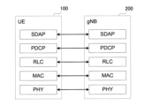
- Figure 2 shows the protocol stack configuration of the wireless interface of the user plane that handles data.
- the user plane radio interface protocol has a physical (PHY) layer, a medium access control (MAC) layer, a radio link control (RLC) layer, a packet data convergence protocol (PDCP) layer, and a service data adaptation protocol (SDAP) layer.
- PHY physical
- MAC medium access control
- RLC radio link control
- PDCP packet data convergence protocol
- SDAP service data adaptation protocol
- the PHY layer performs encoding/decoding, modulation/demodulation, antenna mapping/demapping, and resource mapping/demapping. Data and control information are transmitted between the PHY layer of UE100 and the PHY layer of gNB200 via a physical channel.
- the PHY layer of UE100 receives downlink control information (DCI) transmitted from gNB200 on a physical downlink control channel (PDCCH).
- DCI downlink control information
- PDCCH physical downlink control channel
- RNTI radio network temporary identifier
- the DCI transmitted from gNB200 has CRC (Cyclic Redundancy Code) bits scrambled by the RNTI added.
- the gNB 200 also transmits a synchronization signal block (SSB: Synchronization Signal/PBCH block).
- SSB Synchronization Signal/PBCH block
- the SSB is composed of four consecutive OFDM (Orthogonal Frequency Division Multiplex) symbols, and includes a primary synchronization signal (PSS), a secondary synchronization signal (SSS), a physical broadcast channel (PBCH)/master information block (MIB), and a demodulation reference signal (DMRS) for the PBCH.
- PSS primary synchronization signal
- SSS secondary synchronization signal
- PBCH physical broadcast channel
- MIB master information block
- DMRS demodulation reference signal
- the bandwidth of the SSB is, for example, 240 consecutive subcarriers, i.e., a bandwidth of 20 RBs.
- the MAC layer performs data priority control, retransmission processing using Hybrid Automatic Repeat reQuest (HARQ), and random access procedures. Data and control information are transmitted between the MAC layer of UE100 and the MAC layer of gNB200 via a transport channel.
- the MAC layer of gNB200 includes a scheduler. The scheduler determines the uplink and downlink transport format (transport block size, modulation and coding scheme (MCS)) and the resource blocks to be assigned to UE100.
- MCS modulation and coding scheme
- the RLC layer uses the functions of the MAC layer and PHY layer to transmit data to the RLC layer on the receiving side. Data and control information are transmitted between the RLC layer of UE100 and the RLC layer of gNB200 via logical channels.
- the PDCP layer performs header compression/decompression, encryption/decryption, etc.
- the SDAP layer maps IP flows, which are the units for which the core network controls QoS (Quality of Service), to radio bearers, which are the units for which the AS (Access Stratum) controls QoS. Note that if the RAN is connected to the EPC, SDAP is not necessary.
- Figure 3 shows the configuration of the protocol stack for the wireless interface of the control plane that handles signaling (control signals).
- the protocol stack of the radio interface of the control plane has an RRC (Radio Resource Control) layer and a NAS (Non-Access Stratum) layer instead of the SDAP layer shown in Figure 2.
- RRC Radio Resource Control
- NAS Non-Access Stratum
- RRC signaling for various settings is transmitted between the RRC layer of UE100 and the RRC layer of gNB200.
- the RRC layer controls logical channels, transport channels, and physical channels in response to the establishment, re-establishment, and release of radio bearers.
- RRC connection connection between the RRC of UE100 and the RRC of gNB200
- UE100 is in an RRC connected state.
- RRC connection no connection between the RRC of UE100 and the RRC of gNB200
- UE100 is in an RRC idle state.
- UE100 is in an RRC inactive state.
- the NAS layer which is located above the RRC layer, performs session management, mobility management, etc.
- NAS signaling is transmitted between the NAS layer of UE100 and the NAS layer of AMF300A.
- UE100 also has an application layer, etc.
- AS Access Stratum
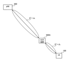
- FIGS. 4 and 5 are diagrams showing examples of application scenarios of the NCR device according to the embodiment.
- 5G/NR is capable of broadband transmission using higher frequency bands.
- Radio signals in high frequency bands such as the millimeter wave band or terahertz wave band have high line-of-sight properties, so reducing the coverage of gNB200 becomes an issue.
- UE100 may be located outside the coverage area of gNB200, for example, outside the area where radio signals can be received directly from gNB200. There may be an obstruction between gNB200 and UE100, and UE100 may not be able to communicate with gNB200 within line-of-sight.
- a repeater device which is a type of relay device that relays wireless signals between a gNB 200 and a UE 100, and an NCR device 500A that can be controlled from a network 5 is introduced into a mobile communication system 1.
- a repeater device may be referred to as a smart repeater device.
- the NCR device 500A amplifies the radio signal (radio wave) received from the gNB 200 and transmits it by directional transmission. Specifically, the NCR device 500A receives the radio signal transmitted by the gNB 200 by beamforming. The NCR device 500A then amplifies the received radio signal without demodulating or modulating it, and transmits the amplified radio signal by directional transmission.
- the NCR device 500A may transmit the radio signal with a fixed directivity (beam).
- the NCR device 500A may transmit the radio signal with a variable (adaptive) directional beam. This allows the coverage of the gNB 200 to be efficiently expanded.
- NCR-MT Mobile termination
- the NCR device 500A has an NCR-Fwd (Forward) 510A, which is a type of repeater that relays wireless signals transmitted between the gNB 200 and the UE 100, specifically, that changes the propagation state of the wireless signal without demodulating or modulating the wireless signal, and an NCR-MT 520A that controls the NCR-Fwd 510A by performing wireless communication with the gNB 200.
- NCR-Fwd Forward
- NCR-MT520A establishes a wireless connection with gNB200 and performs wireless communication with gNB200, thereby controlling NCR device 500A in cooperation with gNB200. This allows efficient coverage expansion to be achieved using NCR device 500A.
- NCR-MT520A controls NCR device 500A according to control from gNB200. Note that NCR-MT520A also has functions similar to those of UE100.
- NCR-MT520A may be configured separately from NCR-Fwd510A.
- NCR-MT520A may be located near NCR-Fwd510A and electrically connected to NCR-Fwd510A.
- NCR-MT520A may be connected to NCR-Fwd510A by wire or wirelessly.
- NCR-MT520A may be configured integrally with NCR-Fwd510A.
- NCR-MT520A and NCR-Fwd510A may be fixedly installed, for example, at the coverage edge (cell edge) of gNB200 or on a wall or window of a building.
- NCR-MT520A and NCR-Fwd510A may be installed, for example, in a vehicle or the like, and may be mobile.
- one NCR-MT520A may control multiple NCR-Fwd510A.
- the configuration is not limited to one in which the NCR-MT 520A directly controls one or more NCR-Fwds 510A, and may be one in which the NCR-MT 520A indirectly controls one or more NCR-Fwds 510A.
- the NCR-MT 520A may control one or more NCR-Fwds 510A via a higher layer (e.g., an application layer).
- the NCR device 500A (NCR-Fwd 510A) dynamically or quasi-statically changes the beam to be transmitted or received.
- the NCR-Fwd 510A forms a beam toward each of the UE 100a and the UE 100b.
- the NCR-Fwd 510A may also form a beam toward the gNB 200.
- the NCR-Fwd 510A transmits a radio signal received from the gNB 200 toward the UE 100a by beamforming, and/or transmits a radio signal received from the UE 100a toward the gNB 200 by beamforming.
- the NCR-Fwd 510A transmits a radio signal received from the gNB 200 to the UE 100b by beamforming, and/or transmits a radio signal received from the UE 100b by beamforming to the gNB 200.
- the NCR-Fwd 510A may form a null (so-called null steering) toward the UE 100 (not shown) and/or the adjacent gNB 200 (not shown) that are not communication partners in order to suppress interference.
- FIG. 6 is a diagram showing an example of a control method for the NCR device 500A according to an embodiment.
- NCR-Fwd510A relays radio signals (also referred to as "UE signals") between gNB200 and UE100.
- UE signals include uplink signals (also referred to as “UE-UL signals”) transmitted from UE100 to gNB200 and downlink signals (also referred to as "UE-DL signals”) transmitted from gNB200 to UE100.
- NCR-Fwd510A relays UE-UL signals from UE100 to gNB200 and UE-DL signals from gNB200 to UE100.
- the radio link between NCR-Fwd510A and UE100 is also referred to as "access link”.
- the radio link between NCR-Fwd510A and gNB200 is also referred to as "backhaul link”.
- NCR-MT520A transmits and receives radio signals (herein referred to as "NCR-MT signals") with gNB200.
- NCR-MT signals include uplink signals (herein referred to as “NCR-MT-UL signals”) transmitted from NCR-MT520A to gNB200, and downlink signals (herein referred to as "NCR-MT-DL signals”) transmitted from gNB200 to NCR-MT520A.
- NCR-MT-DL signals include signaling (e.g., NCR control signals) for controlling NCR device 500A.
- the radio link between NCR-MT520A and gNB200 is also referred to as the "control link.”
- gNB200 directs a beam to NCR-MT520A based on the NCR-MT-UL signal from NCR-MT520A. Because NCR device 500A is co-located with NCR-MT520A, if the backhaul link and the control link have the same frequency, when gNB200 directs a beam to NCR-MT520A, the beam will also be directed to NCR-Fwd510A. gNB200 uses the beam to transmit NCR-MT-DL signals and UE-DL signals. NCR-MT520A receives the NCR-MT-DL signal.
- the functions e.g., antennas
- the functions for transmitting, receiving, or relaying UE signals and/or NCR-MT signals may be integrated in the NCR-Fwd 510A and the NCR-MT 520A.
- the beam includes a transmitting beam and/or a receiving beam.
- a beam is a general term for transmission and/or reception under control to maximize the power of the transmitting wave and/or receiving wave in a specific direction by adjusting/adapting the antenna weight, etc.
- FIG. 7 is a diagram illustrating an example of the configuration of a protocol stack in the NCR device 500A according to an embodiment.
- NCR-Fwd 510A relays wireless signals transmitted and received between gNB 200 and UE 100.
- NCR-Fwd 510A has an RF (Radio Frequency) function that amplifies and relays received wireless signals, and performs directional transmission using beamforming (e.g., analog beamforming).
- RF Radio Frequency
- NCR-MT520A has entities for each layer: Layer 1 and/or Layer 2 (L1/L2), RRC, and NAS.
- L1/L2 Layer 1 and/or Layer 2
- RRC Layer 2
- NAS Layer 1 and/or Layer 2
- NCR-MT520A's L1/L2 (especially PHY, MAC) and RRC are also referred to as "NCR-MT520A's AS.”
- NCR-MT520A may have at least one of an OAM client that communicates with OAM (Operation, Administration, Maintenance) server 400, a NAS layer that communicates with AMF300A, and an F1-AP (Application Protocol) layer.
- OAM Operaation, Administration, Maintenance
- NAS NAS layer that communicates with AMF300A
- F1-AP Application Protocol
- the OAM client, NAS layer, and F1-AP layer of NCR-MT520A are also referred to as the "upper layers of NCR-MT520A" based on the AS of NCR-MT520A.
- a backhaul link is established between gNB200 and NCR-Fwd510A.
- An access link is established between UE100 and NCR-Fwd510A.
- NCR-Fwd510A relays wireless signals transmitted between gNB200 and UE100 via the backhaul link and the access link.
- NCR-Fwd510A changes the propagation state of the wireless signal without demodulating or modulating the wireless signal.
- a control link is established between gNB200 and L1/L2 of NCR-MT520A.
- L1/L2 of NCR-MT520A transmits and receives L1/L2 signaling with gNB200 via the control link.
- An RRC connection is established between gNB200 and RRC of NCR-MT520A.
- RRC of NCR-MT520A transmits and receives RRC messages with gNB200 via the RRC connection.
- NCR-MT520A receives downlink signaling (also referred to as "NCR control signal” or simply "control signal”) from gNB200 via the RRC connection and/or the control link.
- the gNB 200 transmits an NCR control signal to the NCR-MT 520A.
- the NCR control signal may be an RRC message, which is a control signal of the RRC layer (i.e., layer 3).
- the NCR control signal may be a MAC CE (Control Element), which is a control signal of the MAC layer (i.e., layer 2).
- the NCR control signal may be downlink control information (DCI), which is a control signal of the PHY layer (i.e., layer 1).
- DCI downlink control information
- the NCR control signal may be UE-specific signaling.
- the NCR control signal may be broadcast signaling.
- the NCR control signal may be a fronthaul message (e.g., an F1-AP message). If the NCR-MT 520A is a type or part of a base station, the NCR-MT 520A may communicate with the gNB 200 via an Xn AP (Xn-AP), which is an interface between base stations
- the NCR control signal transmitted in the RRC message (and/or MAC CE) and used for static or quasi-static control of the NCR-Fwd 510A is also referred to as "NCR setting information (NCR setting)" or simply “setting information”. Such setting information may be referred to as "Side Control Configuration”.
- the RRC message may be an RRC Reconfiguration message.
- the NCR setting information includes, for example, information for setting the on/off of the NCR-Fwd 510A.
- the NCR setting information may include, for example, information for quasi-static beam setting of the NCR-Fwd 510A.
- the NCR control signal transmitted in the L1/L2 signaling, i.e., DCI (and/or MAC CE) and used for dynamic control of the NCR-Fwd 510A is also referred to as "NCR control information" or simply "control information".
- the NCR control information may also be referred to as "Side Control Information”.
- the CRC bits of the PDCCH carrying the NCR control information are scrambled by a newly introduced dedicated RNTI.
- the dedicated RNTI is also referred to as "NCR-RNTI".
- the NCR control information may include, for example, information on dynamic beam control of the NCR-Fwd 510A.
- the NCR setting information may include information instructing dynamic on/off of the NCR-Fwd 510A.
- NCR device 500A when NCR-MT 520A is in the RRC connected state, NCR device 500A can turn NCR-Fwd 510A on or off according to the NCR control information received from gNB 200. On the other hand, after NCR-MT 520A transitions to the RRC inactive state, NCR device 500A can turn NCR-Fwd 510A on or off according to the latest (last) setting information received from gNB 200.
- NCR control signal e.g., NCR setting information by RRC and/or NCR control information by L1/L2 signaling
- NCR-MT 520A NCR-MT 520A
- NCR-MT520A performs cell selection and triggers RRC connection re-establishment (also referred to as "RRC re-establishment").
- RRC re-establishment also referred to as "RRC re-establishment”
- NCR device 500A turns off NCR-Fwd510A. Note that NCR-Fwd510A is off during the RRC connection re-establishment procedure.
- the NCR control signal may include frequency control information that specifies the center frequency of the radio signal (e.g., component carrier) that NCR-Fwd 510A is to relay.
- NCR-MT 520A controls NCR-Fwd 510A to relay the radio signal having the center frequency indicated by the frequency control information (step S2A).
- the NCR control signal may include multiple pieces of frequency control information that specify different center frequencies. By including frequency control information in the NCR control signal, gNB 200 can specify the center frequency of the radio signal that NCR-Fwd 510A is to relay via NCR-MT 520A.
- the NCR control signal may include mode control information that specifies the operation mode of the NCR-Fwd 510A.
- the mode control information may be associated with frequency control information (center frequency).
- the operation mode may be any of the following modes: a mode in which the NCR-Fwd 510A performs omnidirectional transmission and/or reception, a mode in which the NCR-Fwd 510A performs fixed directional transmission and/or reception, a mode in which the NCR-Fwd 510A performs transmission and/or reception using a variable directional beam, and a mode in which the NCR-Fwd 510A performs MIMO (Multiple Input Multiple Output) relay transmission.
- MIMO Multiple Input Multiple Output
- the operation mode may be any of the following modes: a beamforming mode (i.e., a mode that emphasizes improvement of the desired wave) and a null steering mode (i.e., a mode that emphasizes suppression of interference waves).
- the NCR-MT 520A controls the NCR-Fwd 510A to operate in the operation mode indicated by the mode control information (step S2A).
- the gNB 200 can specify the operation mode of the NCR-Fwd 510A via the NCR-MT 520A.
- the mode in which the NCR device 500A performs non-directional transmission and/or reception is a mode in which the NCR-Fwd 510A performs relaying in all directions, and may be referred to as an omni mode.
- the mode in which the NCR-Fwd 510A performs fixed directional transmission and/or reception may be a directional mode realized by one directional antenna.
- the mode may be a beamforming mode realized by applying fixed phase/amplitude control (antenna weight control) to multiple antennas. Any of these modes may be specified (set) by the gNB 200 to the NCR-MT 520A.
- the mode in which the NCR-Fwd 510A performs transmission and/or reception using a variable directional beam may be a mode in which analog beamforming is performed.
- the mode may be a mode in which digital beamforming is performed.
- the mode may be a mode in which hybrid beamforming is performed.
- the mode may be a mode in which an adaptive beam specific to the UE 100 is formed. Any of these modes may be specified (set) from the gNB 200 to the NCR-MT 520A.
- beam control information described later may be provided from the gNB 200 to the NCR-MT 520A.
- the mode in which the NCR device 500A performs MIMO relay transmission may be a mode in which SU (Single-User) spatial multiplexing is performed.
- the mode may be a mode in which MU (Multi-User) spatial multiplexing is performed.
- the mode may be a mode in which transmit diversity is performed. Any of these modes may be specified (set) from the gNB 200 to the NCR-MT 520A.
- the operation mode may include a mode in which relay transmission by the NCR-Fwd 510A is turned on (activated) and a mode in which relay transmission by the NCR-Fwd 510A is turned off (deactivated). Any of these modes may be specified (set) by an NCR control signal from gNB200 to NCR-MT520A.
- the NCR control signal may include beam control information that specifies the transmission direction, transmission weight, or beam pattern when the NCR-Fwd 510A performs directional transmission.
- the beam control information may be associated with frequency control information (center frequency).
- the beam control information may include a PMI (Precoding Matrix Indicator).
- the beam control information may include beam formation angle information.
- the NCR-MT 520A controls the NCR-Fwd 510A to form the transmission directivity (beam) indicated by the beam control information.
- the gNB 200 can control the transmission directivity of the NCR device 500A via the NCR-MT 520A.
- the NCR control signal may include output control information that specifies the degree to which the NCR-Fwd 510A amplifies the radio signal (amplification gain) or transmission power.
- the output control information may be information indicating a difference value (i.e., a relative value) between the current amplification gain or transmission power and a target amplification gain or transmission power.
- the NCR-MT 520A controls the NCR-Fwd 510A to change the amplification gain or transmission power to the one indicated by the output control information.
- the output control information may be associated with frequency control information (center frequency).
- the output control information may be information that specifies any one of the amplifier gain, beamforming gain, and antenna gain of the NCR-Fwd 510A.
- the output control information may be information that specifies the transmission power of the NCR-Fwd 510A.
- the gNB 200 may transmit an NCR control signal to the NCR-MT 520A for each NCR-Fwd 510A.
- the NCR control signal may include an identifier (NCR identifier) of the corresponding NCR-Fwd 510A.
- the NCR-MT 520A (controller 523) that controls multiple NCR-Fwds 510A determines the NCR-Fwd 510A to which the NCR control signal is to be applied based on the NCR identifier included in the NCR control signal received from the gNB 200. Note that the NCR identifier may be transmitted from the NCR-MT 520A to the gNB 200 together with the NCR control signal, even when the NCR-MT 520A controls only one NCR-Fwd 510A.
- NCR-MT520A controls NCR-Fwd510A based on an NCR control signal from gNB200. This enables gNB200 to control NCR-Fwd510A via NCR-MT520A.
- the NCR device 500A includes an NCR-Fwd 510A, an NCR-MT 520A, and an interface 530.
- the NCR-Fwd 510A has a radio unit 511A and an NCR control unit 512A.
- the radio unit 511A has an antenna unit 511a including multiple antennas (multiple antenna elements), an RF circuit 511b including an amplifier, and a directivity control unit 511c that controls the directivity of the antenna unit 511a.
- the RF circuit 511b amplifies and relays (transmits) radio signals transmitted and received by the antenna unit 511a.
- the RF circuit 511b may convert an analog radio signal into a digital signal and reconvert it into an analog signal after digital signal processing.
- the directivity control unit 511c may perform analog beamforming by analog signal processing.
- the directivity control unit 511c may perform digital beamforming by digital signal processing.
- the directivity control unit 511c may perform hybrid analog and digital beamforming.
- the NCR control unit 512A controls the radio unit 511A in response to a control signal from the NCR-MT 520A.
- the NCR control unit 512A may include at least one processor.
- the NCR-MT 520A has a receiving unit 521, a transmitting unit 522, and a control unit 523.
- the receiving unit 521 performs various receptions under the control of the control unit 523.
- the receiving unit 521 includes an antenna and a receiver.
- the receiver converts a radio signal (wireless signal) received by the antenna into a baseband signal (received signal) and outputs it to the control unit 523.
- the transmitting unit 522 performs various transmissions under the control of the control unit 523.
- the transmitting unit 522 includes an antenna and a transmitter.
- the transmitter converts a baseband signal (transmitted signal) output by the control unit 523 into a radio signal and transmits it from the antenna.
- the control unit 523 performs various controls in the NCR-MT 520A.
- the operations of the NCR-MT 520A (and the NCR device 500A) described above and below may be operations under the control of the control unit 523.
- the control unit 523 includes at least one processor and at least one memory.
- the memory stores the programs executed by the processor and information used in the processing by the processor.
- the processor may include a baseband processor and a CPU (Central Processing Unit).
- the baseband processor performs modulation/demodulation and encoding/decoding of baseband signals.
- the CPU executes the programs stored in the memory to perform various processes.
- the control unit 523 also executes the functions of at least one of the layers of PHY, MAC, RRC, and F1-AP.
- the interface 530 electrically or logically connects the NCR-Fwd 510A and the NCR-MT 520A.
- the control unit 523 of the NCR-MT 520A controls the NCR-Fwd 510A via the interface 530.
- the interface 530 may be a logical entity of a higher layer (e.g., an application layer).
- the receiver 521 of the NCR-MT 520A receives signaling (NCR control signal) used to control the NCR device 500A from the gNB 200 via wireless communication.
- the controller 523 of the NCR-MT 520A controls the NCR device 500A based on the signaling. This enables the gNB 200 to control the NCR-Fwd 510A via the NCR-MT 520A.
- FIG. 9 is a diagram showing the configuration of a UE 100 (user device) according to an embodiment.
- the UE 100 has a receiving unit 110, a transmitting unit 120, and a control unit 130.
- the receiving unit 110 and the transmitting unit 120 configure a wireless communication unit that performs wireless communication with the gNB 200.
- the receiving unit 110 performs various types of reception under the control of the control unit 130.
- the receiving unit 110 includes an antenna and a receiver.
- the receiver converts the radio signal received by the antenna into a baseband signal (received signal) and outputs it to the control unit 130.
- the transmitting unit 120 performs various transmissions under the control of the control unit 130.
- the transmitting unit 120 includes an antenna and a transmitter.
- the transmitter converts the baseband signal (transmission signal) output by the control unit 130 into a radio signal and transmits it from the antenna.
- the control unit 130 performs various controls and processes in the UE 100. Such processes include processes for each layer described below. The operations of the UE 100 described above and below may be operations under the control of the control unit 130.
- the control unit 130 includes at least one processor and at least one memory.
- the memory stores programs executed by the processor and information used in the processing by the processor.
- the processor may include a baseband processor and a CPU.
- the baseband processor performs modulation/demodulation and encoding/decoding of baseband signals.
- the CPU executes programs stored in the memory to perform various processes.
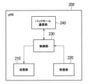
- FIG. 10 is a diagram showing a configuration example of a gNB 200 (base station) according to the embodiment.
- the gNB 200 has a transmitter 210, a receiver 220, a controller 230, and a backhaul communication unit 240.
- the transmitting unit 210 performs various transmissions under the control of the control unit 230.
- the transmitting unit 210 includes an antenna and a transmitter.
- the transmitter converts a baseband signal (transmission signal) output by the control unit 230 into a radio signal and transmits it from the antenna.
- the receiving unit 220 performs various receptions under the control of the control unit 230.
- the receiving unit 220 includes an antenna and a receiver.
- the receiver converts a radio signal received by the antenna into a baseband signal (reception signal) and outputs it to the control unit 230.
- the transmitting unit 210 and the receiving unit 220 may be capable of beamforming using multiple antennas.
- the control unit 230 performs various controls in the gNB 200.
- the operations of the gNB 200 described above and below may be operations under the control of the control unit 230.
- the control unit 230 includes at least one processor and at least one memory.
- the memory stores programs executed by the processor and information used in processing by the processor.
- the processor may include a baseband processor and a CPU.
- the baseband processor performs modulation/demodulation and encoding/decoding of baseband signals.
- the CPU executes programs stored in the memory to perform various processes.
- the backhaul communication unit 240 is connected to adjacent base stations via an inter-base station interface.
- the backhaul communication unit 240 is connected to the AMF/UPF 300 via a base station-core network interface.
- the gNB is composed of a CU (Central Unit) and a DU (Distributed Unit) (i.e., the functions are divided), and the two units may be connected via an F1 interface.
- the transmitter 210 of the gNB 200 transmits signaling (NCR control signal) used to control the NCR-Fwd 510A to the NCR-MT 520A via wireless communication. This enables the gNB 200 to control the NCR device 500A via the NCR-MT 520A.
- signaling NCR control signal
- FIGS. 11 and 12 are diagrams for explaining the operation of the mobile communication system 1 according to the first embodiment.
- the NCR device 500A is in an RRC connected state in cell a (first cell) of the gNB 200a.
- the gNB 200a transmits an RRC Reconfiguration message including the NCR setting to the NCR device 500A.
- the NCR device 500A receives the RRC Reconfiguration message including the NCR setting from the gNB 200a (cell a) and performs relay operation using the NCR setting.
- the NCR setting includes a periodic beam indication.
- the periodic beam indication the period and the beam are set in the RRC.
- the NCR device 500A performs periodic beamforming based on the periodic beam indication.
- gNB 200a transmits an RRC Release message including a suspend setting to NCR device 500A.
- NCR device 500A receives the RRC Release message from gNB 200a (cell a) and transitions to the RRC inactive state.
- the RRC Release message for transitioning NCR-MT520A from the RRC connected state to the RRC inactive state includes a timer value.
- the NCR-MT520A controls the NCR-Fwd510A according to the latest (last) NCR settings.
- the NCR-MT520A controls the NCR-Fwd510A to continue periodic beamforming operation according to the NCR settings (latest settings) received in STEP 1.
- NCR-MT 520A in the RRC inactive state performs cell reselection from cell a (first cell) to cell b (second cell).
- NCR-MT 520A turns off NCR-Fwd 510A (i.e., stops relay operation).
- the NCR-MT 520A starts a timer with the above timer value set in response to cell reselection from cell a to cell b. At least while the timer is running, the NCR-MT 520A retains the NCR settings (latest settings) without discarding them, even if the NCR-Fwd 510A is off.
- cell b is managed by gNB 200b, which is different from gNB 200a that manages cell a.
- cells a and b may be managed by the same gNB 200.
- NCR-MT 520A reselects cell a within a predetermined time after reselecting cell b, it resumes relay operation using the NCR setting (latest setting). Specifically, if NCR-MT 520A reselects cell a before the timer expires, it resumes periodic beamforming using the NCR setting (latest setting).
- NCR-MT 520A in the RRC inactive state reselects the original cell within a specified period after reselecting another cell, it restores (turns on) the operation of NCR-Fwd 510A according to the latest settings.
- NCR-MT 520A in the RRC inactive state reselects the original cell after a specified period has elapsed after reselecting another cell, it continues to turn off NCR-Fwd 510A.
- the NCR-MT520A if the NCR-MT520A returns to the original cell after temporarily camping on another cell, it can autonomously resume relay operations, allowing for efficient control of relay operations.
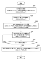
- FIG. 13 is a flow diagram showing an example of the operation of the NCR device 500A according to the first embodiment.
- NCR-MT520A in the RRC connected state receives an NCR setting from gNB200.
- the NCR setting includes a periodic beam indication.
- NCR-MT520A may store the cell ID of the serving cell (cell a) when the NCR setting is performed.
- step S12 the NCR-MT520A in the RRC connected state performs relay operation with periodic beamforming using the NCR settings received in step S11.
- NCR-MT520A in the RRC connected state receives an RRC Release message including a timer value from gNB200.
- the RRC Release message includes a suspend setting, and NCR-MT520A transitions to the RRC inactive state in response to the suspend setting.
- step S14 the NCR-MT520A in the RRC inactive state continues relay operation with periodic beamforming using the NCR settings received in step S11.
- NCR-MT 520A in the RRC inactive state performs cell reselection to another cell (cell b).
- NCR-MT 520A in the RRC inactive state turns off NCR-Fwd 510A and starts the timer set to the timer value received in step S13.
- NCR-MT520A determines whether or not to perform cell reselection to the original cell (cell a) where NCR setting was performed. Note that NCR-MT520A may identify the original cell by comparing the stored cell ID with the cell ID of the reselected cell.
- step S17 NCR-MT 520A determines whether the timer started in step S15 is running (has not yet expired). If it is determined that the timer has expired (step S17: NO), NCR-MT 520A keeps NCR-Fwd 510A off. NCR-MT 520A may discard the NCR settings (latest settings) that it holds when the timer expires.
- step S18 NCR-MT520A turns on NCR-Fwd510A and resumes relay operation with periodic beamforming using the NCR settings (latest settings).
- the second embodiment will be described, focusing mainly on the differences from the first embodiment.
- the second embodiment is an embodiment related to beam fault detection and recovery performed by the NCR-MT520A. Note that the second embodiment may be implemented separately from the first embodiment. The second embodiment may be implemented in combination with the first embodiment.
- General beam failure detection also referred to as "BFD"
- beam failure recovery also referred to as "BFR”
- gNB200 sets SSB or CSI (Channel State Information)-RS to UE100 as a reference signal (RS) for BFD.
- RS Reference Signal
- the MAC entity of UE100 in the RRC connected state declares (detects) beam failure when the number of beam failure instance indicators from the physical layer reaches a threshold (maximum count value) set by gNB200 before the timer set by gNB200 expires.
- the MAC entity of the UE 100 After beam failure is detected in the primary cell (PCell), the MAC entity of the UE 100 performs the following: - Triggering BFR by initiating a random access procedure in the PCell; - Selecting an appropriate beam to perform BFR (if gNB200 provides dedicated random access resources for a particular beam, it is prioritized by UE100); - If the random access procedure includes a contention-based random access, include an indication of beam failure at the PCell in the Beam Failure Recovery (BFR) MAC Control Element (CE).
- BFR Beam Failure Recovery
- CE MAC Control Element
- UE100 considers BFR for the PCell to be completed.
- NCR device 500A can continue relaying operations according to the latest NCR settings. Therefore, it is desirable for NCR-MT 520A to be able to execute BFD and BFR even in the RRC inactive state. For example, when NCR-MT 520A is in the RRC inactive state and NCR-Fwd 510A is on, the NCR device 500A can consider a method of turning off NCR-Fwd 510A in response to detecting beam interference with gNB 200.
- FIG. 14 is a diagram for explaining the operation of the mobile communication system 1 according to the second embodiment.
- the NCR device 500A is in an RRC connected state in the cell of the gNB 200.
- the gNB 200 transmits an RRC Reconfiguration message including the NCR setting to the NCR device 500A.
- the NCR device 500A receives the RRC Reconfiguration message including the NCR setting from the gNB 200 and performs relay operation using the NCR setting.
- the NCR setting may include a periodic beam indication. That is, the NCR setting includes information for setting to perform relay operation with periodic beamforming, and the NCR-Fwd 510A is set to on. Such setting information is an example of first setting information regarding relay operation.
- NCR-MT520A receives first setting information regarding relay operation from gNB200.
- gNB200 transmits an RRC Release message including a suspend setting to NCR device 500A.
- NCR device 500A receives the RRC Release message from gNB200 and transitions to the RRC inactive state.
- the RRC Reconfiguration message sent from gNB200 to NCR-MT520A in STEP 1, or the RRC Release message sent from gNB200 to NCR-MT520A in STEP 2 includes second setting information regarding whether NCR-MT520A will perform beam interference detection processing (BFD) with gNB200 in the RRC inactive state.
- BFD beam interference detection processing
- NCR-MT520A receives second setting information from gNB200 regarding whether NCR-MT520A will perform beam interference detection processing with gNB200 in the RRC inactive state.
- gNB200 may provide the second setting information to NCR-MT520A by broadcast signaling. For example, gNB200 may transmit a system information block (SIB) including the second setting information to UE100.
- SIB system information block
- NCR-MT 520A controls NCR-Fwd 510A according to the latest NCR settings.
- NCR-MT 520A controls the relay operation (NCR-Fwd 510A) based on the first setting information, and controls BFD (and BFR) based on the second setting information.
- NCR-MT520A receives second setting information from gNB200 regarding whether or not to perform beam interference detection processing with gNB200 in the RRC inactive state.
- NCR-MT520A in the RRC inactive state controls BFD (and BFR) based on the second setting information. This makes it possible to appropriately control BFD (and BFR) performed by NCR-MT520A in the RRC inactive state.
- the basic operation of BFD performed by NCR-MT520A in the RRC inactive state may be an operation that applies general BFD.
- the MAC entity of NCR-MT520A may perform BFD in the RRC inactive state by continuing to use the reference signal (RS), timer value, and maximum count value for BFD set by gNB200 in the RRC connected state.
- RS reference signal
- the MAC entity of NCR-MT520A in the RRC inactive state declares (detects) beam failure when the number of beam failure instance indicators from the physical layer reaches the threshold (maximum count value) set by gNB200 before the timer set by gNB200 expires.
- At least one of the reference signal (RS), timer value, and maximum count value for the RRC inactive state may be a parameter independent of the reference signal (RS), timer value, and maximum count value for the RRC connected state.
- the second setting information may include information for setting at least one of the reference signal (RS), timer value, and maximum count value for the RRC inactive state.
- the NCR-MT520A may be considered to be specified (configured) to perform BFD in the RRC inactive state.
- the second setting information may include information specifying whether or not the NCR-MT520A performs a detection process (BFD) in the RRC inactive state. That is, the gNB200 may set the NCR-MT520A as to whether or not to perform BFD in the RRC inactive state.
- BFD detection process
- NCR-MT520A when NCR-MT520A is in the RRC inactive state, in response to the detection of a beam failure by the detection process (BFD), NCR-MT520A may initiate an RRC connection resume for NCR-MT520A to transition to the RRC connected state. That is, when NCR-MT520A detects a beam failure in the RRC inactive state, it may resume the RRC connection and transition to the RRC connected state. For example, when NCR-MT520A initiates the RRC connection resume, it selects an available beam before transmitting a random access preamble (Msg1) on the physical random access channel (PRACH), and transmits Msg1 using the PRACH resource associated with that beam (SSB index).
- Msg1 random access preamble
- PRACH physical random access channel
- the gNB200 determines the beam (SSB index) selected by the NCR-MT520A from the resources for which Msg1 was received, and transmits a random access response (Msg2) using the antenna weight corresponding to that beam.
- Msg2 includes a UL grant, and the NCR-MT520A transmits an RRC Resume Request message (Msg3) to the gNB200. Then, the NCR-MT520A receives an RRC Resume message (Msg4) from the gNB200, and transitions to the RRC connected state.
- the second setting information may include information specifying whether to continue relay operation when NCR-MT520A detects a beam failure in an RRC inactive state. For example, when gNB200 detects a beam failure in an RRC inactive state, it may set NCR-MT520A as to whether to turn off NCR-Fwd510A or to keep it on.
- the NCR-MT520A when the NCR-MT520A is in the RRC inactive state, it may stop relaying operation in response to the detection of a beam failure by the detection process (BFD) and failure to identify a candidate beam that satisfies a specified quality standard. For example, if the NCR-MT520A detects a beam failure in the RRC inactive state and is unable to capture a new beam that satisfies the quality standard (within a certain time or within a certain number of recovery attempts), it may turn off the NCR-Fwd510A.
- BFD detection process
- FIG. 15 is a flow diagram showing an example of the operation of the NCR device 500A according to the second embodiment.
- NCR-MT520A receives an RRC Reconfiguration message including an NCR setting from gNB200.
- the NCR setting includes first setting information related to relay operation.
- the first setting information includes setting information indicating that NCR-Fwd510A is to be turned on.
- the first setting information may include a periodic beam indication.
- the NCR setting may further include second setting information related to whether or not NCR-MT520A performs a beam interference detection process (BFD) with gNB200 in an RRC inactive state.
- BFD beam interference detection process
- the second setting information is also referred to as "BFD/BFR setting for RRC inactive state.”
- the NCR-MT 520A in the RRC connected state may perform relay operation using the NCR-Fwd 510A in the ON state based on the first setting information included in the NCR setting received in step S11.
- NCR-MT520A in the RRC connected state receives an RRC Release message including a suspend setting from gNB200.
- NCR-MT520A transitions to an RRC inactive state in response to the suspend setting.
- the RRC Release message may include a BFD/BFR setting (second setting information) for the RRC inactive state.
- the BFD/BFR configuration for the RRC inactive state includes at least one of the following configuration information a) to c).
- the setting may include information specifying whether or not to resume RRC connection when a beam failure is detected in an RRC inactive state.
- the setting may include information specifying whether to turn off the NCR-Fwd 510A while continuing the RRC inactive state, or to keep the NCR-Fwd 510A on according to the latest setting.
- the setting may include information specifying whether or not to perform BFR.
- the setting may include a parameter that specifies the conditions for determining that BFR has failed.
- the parameter may include a timer value for the determination and/or an upper limit value for the number of attempts for the determination.
- the NCR-MT 520A in the RRC inactive state may determine that BFR has failed in response to the inability to discover (capture) a candidate beam that satisfies a predetermined quality criterion within the timer value, or the unsuccessful random access procedure for a candidate beam that satisfies a predetermined quality criterion.
- the NCR-MT 520A in the RRC inactive state may determine that BFR has failed in response to the number of times that a candidate beam that does not satisfy a predetermined quality criterion has been discovered reaching the upper limit value, or the number of times that a random access procedure for a candidate beam that satisfies a predetermined quality criterion has failed reaching the upper limit value.
- the setting may include information specifying the process to be taken when BFR fails.
- the information may include information specifying whether or not NCR-MT 520A will resume the RRC connection.
- the information may include information specifying whether NCR-Fwd 510A will be turned off or kept on.
- step S24 the NCR-MT 520A that has transitioned to the RRC inactive state performs relay operation using the NCR-Fwd 510A in the ON state based on the first setting information included in the NCR setting (latest setting) in the RRC connected state. Also, the NCR-MT 520A in the RRC inactive state performs BFD based on the BFD/BFR setting (second setting information) for the RRC inactive state.
- step S25 the NCR-MT520A in the RRC inactive state checks whether a beam obstruction has been detected by BFD. If no beam obstruction has been detected, the process returns to step S24.
- step S26 the NCR-MT520A in the RRC inactive state performs an operation (e.g., BFR and/or RRC connection resume) specified in the BFD/BFR setting for the RRC inactive state based on the BFD/BFR setting (second setting information).
- an operation e.g., BFR and/or RRC connection resume
- the gNB 200 explicitly sets the NCR-MT 520A as to whether or not to perform beam failure detection (BFD) and/or beam failure recovery (BFR), but this is not limited to this.
- the NCR-MT 520A can determine whether or not to perform beam failure detection and/or beam failure recovery processing in the RRC inactive state based on the operating state of the NCR-Fwd 510A.
- NCR-MT520A transitions to the RRC inactive state
- NCR-Fwd510A when NCR-MT520A transitions to the RRC inactive state, if NCR-Fwd510A is in the on state (e.g., performing periodic beamforming operation), NCR-MT520A performs beam failure detection and/or beam failure recovery processing in the RRC inactive state. Also, if NCR-Fwd510A is in the off control (not performing relay operation), beam failure detection and/or beam failure recovery processing in the RRC inactive state is not performed. This allows NCR-MT520A to determine whether or not beam failure detection and/or beam failure recovery processing is required in the RRC inactive state without explicit setting from gNB200.
- the relay device is a RIS (Reconfigurable Intelligent Surface) device 500B that changes the propagation direction of an incident radio wave (wireless signal) by reflection or refraction.
- RIS Reconfigurable Intelligent Surface
- RIS is a type of repeater (hereinafter also referred to as "RIS-Fwd") that can perform beamforming (directional control) in the same way as NCR by changing the properties of the metamaterial.
- the range (distance) of the beam may also be changeable by controlling the reflection direction and/or refraction direction of each unit element.
- the configuration may be such that, in addition to controlling the reflection direction and/or refraction direction of each unit element, it can also focus (direct the beam) on a nearby UE or a distant UE.
- the RIS device 500B has a new UE (hereinafter referred to as "RIS-MT") 520B, which is a control terminal for controlling the RIS-Fwd 510B.
- the RIS-MT 520B establishes a wireless connection with the gNB 200 and performs wireless communication with the gNB 200, thereby controlling the RIS-Fwd 510B in cooperation with the gNB 200.
- the RIS-Fwd 510B may be a reflective RIS.
- Such a RIS-Fwd 510B changes the propagation direction of the incident radio waves by reflecting the radio waves.
- the reflection angle of the radio waves can be variably set.
- the RIS-Fwd 510B reflects the radio waves incident from the gNB 200 toward the UE 100.
- the RIS-Fwd 510B may be a transparent RIS.
- Such a RIS-Fwd 510B changes the propagation direction of the radio waves by refracting the incident radio waves.
- the refraction angle of the radio waves can be variably set.
- FIG. 17 is a diagram showing an example of the configuration of a RIS-Fwd (repeater) 510B and a RIS-MT (control terminal) 520B according to the second embodiment.
- the RIS-MT 520B has a receiver 521, a transmitter 522, and a controller 523. This configuration is the same as that of the above-mentioned embodiment.
- the RIS-Fwd 510B has a RIS 511B and a RIS controller 512B.
- the RIS 511B is a metasurface made of a metamaterial.
- the RIS 511B is made by arranging very small structures in an array relative to the wavelength of radio waves, and by making the structures have different shapes depending on the arrangement location, it is possible to arbitrarily design the direction and/or beam shape of the reflected wave.
- the RIS 511B may be a transparent dynamic metasurface.
- RIS511B is configured by overlaying a transparent glass substrate on a transparent metasurface substrate on which a large number of small structures are regularly arranged, and by minutely moving the overlaid glass substrate, it may be possible to dynamically control three patterns: a mode that transmits incident radio waves, a mode that transmits some of the radio waves and reflects some of them, and a mode that reflects all of the radio waves.
- RIS control unit 512B controls RIS511B in response to a RIS control signal from control unit 523 of RIS-MT520B.
- RIS control unit 512B may include at least one processor and at least one actuator. The processor decodes the RIS control signal from control unit 523 of RIS-MT520B and drives the actuator in response to the RIS control signal.
- the relay device performing relay transmission is the NCR device 500A or the RIS device 500B.
- the relay device performing relay transmission is not limited to the NCR device 500A or the RIS device 500B, and may be an IAB (Integrated Access and Backhaul) node defined in the 3GPP technical specifications.
- Each of the above-mentioned operation flows can be implemented not only separately but also by combining two or more operation flows. For example, some steps of one operation flow can be added to another operation flow, or some steps of one operation flow can be replaced with some steps of another operation flow. In each flow, it is not necessary to execute all steps, and only some of the steps can be executed.
- the base station is an NR base station (gNB)
- the base station may also be an LTE base station (eNB).
- the base station may also be a relay node such as an IAB node.
- the base station may also be a Distributed Unit (DU) of an IAB node.
- gNB NR base station
- eNB LTE base station
- DU Distributed Unit
- the base station is an NR base station (gNB)
- the base station may be an LTE base station (eNB) or a 6G base station.
- the base station may also be a relay node such as an IAB (Integrated Access and Backhaul) node.
- the base station may be a DU of an IAB node.
- the UE 100 may also be an MT (Mobile Termination) of an IAB node.
- UE100 may be a terminal function unit (a type of communication module) that allows a base station to control a repeater that relays signals.
- a terminal function unit is called an MT.
- Examples of MT include, in addition to IAB-MT, NCR (Network Controlled Repeater)-MT and RIS (Reconfigurable Intelligent Surface)-MT.
- network node primarily refers to a base station, but may also refer to a core network device or part of a base station (CU, DU, or RU).
- a network node may also be composed of a combination of at least a part of a core network device and at least a part of a base station.
- a program may be provided that causes a computer to execute each process performed by the communication device according to the above-described embodiment, for example, the UE100 (NCR-MT520A, RIS-MT520B) or the gNB200.
- the program may be recorded on a computer-readable medium.
- the computer-readable medium on which the program is recorded may be a non-transient recording medium.
- the non-transient recording medium is not particularly limited, and may be, for example, a recording medium such as a CD-ROM or a DVD-ROM.
- circuits that execute each process performed by the UE100 or the gNB200 may be integrated, and at least a part of the UE100 or the gNB200 may be configured as a semiconductor integrated circuit (chip set, SoC: System on a chip).
- a program may be provided that causes a computer to execute each process performed by the UE100, the gNB200, or the relay device.
- the program may be recorded on a computer-readable medium.
- the computer-readable medium on which the program is recorded may be a non-transient recording medium.
- the non-transient recording medium is not particularly limited, and may be, for example, a recording medium such as a CD-ROM or a DVD-ROM.
- a circuit that executes each process performed by the UE100, the gNB200, or the relay device may be integrated, and at least a part of the UE100, the gNB200, or the relay device may be configured as a semiconductor integrated circuit (chip set, SoC: System on a chip).
- UE100, gNB200 (network node) or relay device may be implemented in circuitry or processing circuitry, including general-purpose processors, application-specific processors, integrated circuits, ASICs (Application Specific Integrated Circuits), CPUs (Central Processing Units), conventional circuits, and/or combinations thereof, programmed to realize the described functions.
- Processors include transistors and other circuits and are considered to be circuitry or processing circuitry.
- Processors may be programmed processors that execute programs stored in memory.
- circuitry, units, and means are hardware that is programmed to realize the described functions or hardware that executes them.
- the hardware may be any hardware disclosed herein or any hardware known to be programmed or capable of performing the described functions. If the hardware is a processor considered to be a type of circuitry, the circuitry, means, or unit is a combination of hardware and software used to configure the hardware and/or processor.
- the terms “based on” and “depending on/in response to” do not mean “based only on” or “only in response to,” unless otherwise specified.
- the term “based on” means both “based only on” and “based at least in part on.”
- the term “in response to” means both “only in response to” and “at least in part on.”
- the terms “include,” “comprise,” and variations thereof do not mean including only the items listed, but may include only the items listed, or may include additional items in addition to the items listed.
- the term “or” as used in this disclosure is not intended to mean an exclusive or.
- any reference to elements using designations such as “first,” “second,” etc., as used in this disclosure is not intended to generally limit the quantity or order of those elements. These designations may be used herein as a convenient way to distinguish between two or more elements. Thus, a reference to a first and second element does not imply that only two elements may be employed therein, or that the first element must precede the second element in some manner.
- articles are added by translation such as, for example, a, an, and the in English, these articles are intended to include the plural unless the context clearly indicates otherwise.
- a communication method performed by a relay device having a relay operation for relaying a radio signal transmitted between a network node and a user device, and a control terminal for receiving a control signal used to control the relay device from the network node comprising: receiving configuration information related to the relay operation from a first cell; performing the relay operation using the configuration information when the control terminal is in a radio resource control (RRC) inactive state in the first cell; When a cell reselection from the first cell to the second cell is performed, stopping the relay operation; when cell reselection to the first cell is performed within a predetermined time after cell reselection to the second cell, resuming the relay operation using the configuration information.
- RRC radio resource control
- step of resuming the relay operation includes a step of resuming the relay operation using the configuration information when the cell reselection to the first cell is performed before the timer expires.
- the setting information includes a periodic beamforming setting in the relay operation,
- the communication method according to any one of Supplementary Note 1 to 4, wherein the step of resuming the relay operation includes a step of resuming the periodic beamforming using the configuration information.
- a repeater that performs a relay operation of relaying a radio signal transmitted between a network node and a user equipment; a control terminal that receives a control signal used to control the repeater from the network node;
- the control terminal A receiving unit that receives setting information related to the relay operation from a first cell;
- a control unit that controls the relay to perform the relay operation using the configuration information when the control terminal is in a radio resource control (RRC) inactive state in the first cell,
- RRC radio resource control
- the control unit is When cell reselection from the first cell to the second cell is performed, the relay operation is stopped; when cell reselection to the first cell is performed within a predetermined time after cell reselection to the second cell is performed, the relay device resumes the relay operation using the configuration information.
- a communication method performed by a relay device having a relay operation for relaying a radio signal transmitted between a network node and a user device, and a control terminal for receiving a control signal used to control the relay device from the network node comprising: receiving first configuration information from the network node regarding the relay operation; receiving second setting information from the network node regarding whether or not the control terminal performs a beam interference detection process with the network node in a radio resource control (RRC) inactive state; When the control terminal is in the RRC inactive state, controlling the relay operation based on the first setting information and controlling the detection process based on the second setting information.
- RRC radio resource control
- a repeater that performs a relay operation of relaying a radio signal transmitted between a network node and a user equipment; a control terminal that receives a control signal used to control the repeater from the network node; The control terminal a receiving unit that receives first setting information regarding the relay operation from the network node and receives second setting information regarding whether or not the control terminal performs a beam failure detection process with the network node in a radio resource control (RRC) inactive state from the network node; a control unit that, when the control terminal is in the RRC inactive state, controls the relay operation based on the first setting information and controls the detection process based on the second setting information.
- RRC radio resource control
- RAN#99 has approved a three-month extension for the work item on Network Controlled Repeaters (NCRs) to resolve remaining issues for RAN2#119bis-e, RAN2#120, and RAN2#121.
- NCRs Network Controlled Repeaters
- This appendix discusses the open/potential issues remaining for RAN2 in the NCR.
- Proposal 1 In Rel-18, the "wake-up timer" IE will not be defined in the RRC Release message.
- OAM-based solutions That is, the OAM server generates DL OAM traffic (U-plane data) that triggers the AMF to initiate CN paging to the NCR-MT. However, it is assumed that there is no way for the gNB to send UL OAM traffic (U-plane data, e.g., indicating that it has been released to IDLE) when the NCR-MT receives an RRC release, so it is unclear how the OAM server knows that the NCR-MT is idle.
- U-plane data e.g., indicating that it has been released to IDLE
- DL OAM traffic could be an option for AMF to trigger paging of idle NCR-MTs, but it would require coordination between gNB-OAM and NCR-OAM, leading to inefficient network operations and poor interoperability.
- the OAM client can use the released state of the NCR-MT as well as failure states (e.g., RLF, RRC resume failure), and initial access state (e.g., power on) to determine the transition of the NCR-MT to an idle state.
- failure states e.g., RLF, RRC resume failure
- initial access state e.g., power on
- the OAM client may generate UL OAM traffic (i.e., U-plane data) to connect with the OAM server, etc.
- the UL packets trigger the RRC connection establishment procedure as they do today. That is, for an idle NCR-MT, the NCR-MT starts the RRC connection establishment immediately after it is released from the gNB, since the RRC connection establishment is an automatic process.
- Observation 4 The use of UL OAM traffic is another option to trigger the NCR-MT to initiate RRC connection establishment, but it can occur immediately after the gNB releases the NCR-MT to the idle state.
- a wake-up timer was proposed as a trigger for the NCR-MT to return to the RRC connection and was discussed in RAN2#121 offline, online, and RAN2#121bis-e offline, online.
- the idea is that the NCR-MT starts the timer (if configured in the RRC release), and when the timer expires, the NCR-MT initiates the RRC connection establishment procedure.
- This simple solution solves the challenge mentioned in Observation 3 (especially when the OAM server does not implement automatic generation of DL traffic such as keep-alive messages) and allows the gNB to control the idle NCR-MT.
- Keep-alive messages as an OAM-based solution would require a large number of unnecessary messages, especially if the gNB rarely puts the NCR-MT in idle state, but this is up to the gNB implementation.
- Wake-up timers can solve the issues identified in Observation 3, especially when the OAM server does not implement so-called keep-alive messages and the RRC connection control is entirely under the control of the gNB.
- the AS can operate in the same way as if it had received a paging message, i.e., the AS indicates the UE-ID (i.e., UE-Identity) to the NAS.
- the NAS can also operate as if the access attempt is an MT access (i.e., Access Identity 0 and Access Category 0 of "MT_acc"), so the AS can set the establishment cause with the MT access according to the NAS access attempt. Since the expiration of the wake-up timer means that the network (i.e., gNB) calls back the NCR-MT to connected, this establishment cause (i.e., MT access) is considered to be in line with the current definition. This solution has no impact (or little impact) on the NAS specification, but the AS specification needs to be slightly modified as the behavior when the timer expires.
- the AS informs the NAS when the wake-up timer expires, and the NAS requests the establishment of a signaling connection.
- This is considered a new definition of an access attempt, and so besides the slight impact on the AS specification of the new behavior on timer expiration, it may require, for example, the addition of procedural clarifications (or annotations) to the NAS specification.
- Another option would be for the AS to forward the wake-up timer value when set in the RRC release.
- the NAS would handle the timer and request the establishment of a signaling connection on timer expiry.
- This solution would require the timer handling to be specified in the NAS specification in addition to the new definition of the access attempt above. Therefore, in addition to the new behavior in the AS specification, this option has the most impact on the NAS specification.
- Wake-up timers have no (or only a very small) impact on the operation of the NAS as long as the timers are processed by the AS.
- the gNB will always choose not to set the timer on RRC release, i.e., this option is not harmful and ensures efficient network operation and interoperability.
- Proposal 1 RAN2 should agree to introduce a wake-up timer for gNB to control idle NCR-MT and establish RRC connection.
- Proposal 2 RAN2 should discuss whether the AS should act as if it has received a paging message, i.e., whether the AS should indicate its UE-ID to the NAS when the wake-up timer expires.
- Proposal 1 is acceptable, the timer value needs to be discussed.
- 300 seconds or 5 minutes is, for example, a typical period for a UE to exclude a prohibited cell from candidates for cell reselection, and can be the minimum value of this timer.
- a gNB may not use NCR during periods of low traffic (e.g., at night) and may put NCR in idle state. Therefore, it is considered reasonable to set the upper limit of the timer value to 12 hours. If the timer value is 8 bits, the mapping would be, for example, "300 seconds (5 minutes), 10 minutes, 30 minutes, 60 minutes (1 hour), 3 hours, 12 hours.”
- Proposal 3 RAN2 should discuss the range of wake-up timer values (e.g., from 300 seconds to 12 hours).
- Proposal 4 RAN2 should discuss how many bits the wake-up timer setting should be (e.g., baseline is 8 bits).
- Another possibility is a prohibition timer, which causes the NCR-MT to start a timer (if configured in the RRC release) and prohibits the NCR-MT from initiating the RRC connection establishment procedure while the timer is running.
- This solution solves the problem in observation 3 (especially if the OAM server implements frequent automatic generation of DL traffic such as keep-alive messages) and the challenge in observation 4, and allows the gNB to control even idle NCR-MTs.
- Observation 8 Prohibit timers, like observation 4, can solve the problem identified in observation 3 (especially when keep-alive messages occur frequently), and the RRC connection control of NCR-MT is entirely under the control of the gNB.
- an idle NCR-MT can also be network controlled. This is considered more efficient as it does not require two separate timers for the wake-up timer and the inhibit timer.
- Proposal 5 If Proposal 1 is acceptable, RAN2 should further discuss whether to prohibit NCR-MT from initiating RRC connection establishment while the wake-up timer is running, i.e., whether the wake-up timer also functions as a prohibition timer (one timer).
- RRC connection establishment via UL traffic (e.g. UL OAM client packets) will be forbidden, but it is worth considering whether the same is really true for DL traffic (e.g. DL OAM server packets). If RRC connection establishment via DL traffic is forbidden, the NCR will be unreachable from the network/OAM client while the timer is running. Therefore, the prohibition timer should only apply to RRC connection establishment via UL traffic. For example, if the gNB wants to prevent the NCR-MT from returning to connected via DL traffic (e.g. by OAM server keep-alive messages). Therefore, whether this restriction should be configurable by the gNB is a separate issue.
- Proposal 6 If proposal 5 can be agreed upon, RAN2 should further discuss whether the prohibition timer can be applied only to UL traffic (OAM client, etc.), i.e., whether RRC connection establishment is allowed for DL traffic (OAM server, paging reception, etc.) when the timer is running.
- OAM client i.e., whether RRC connection establishment is allowed for DL traffic (OAM server, paging reception, etc.) when the timer is running.
- Proposal 7 If Proposal 6 can be agreed upon, RAN2 should further discuss whether the restrictions can be set by the gNB, i.e., whether the prohibition timer applies only to UL traffic or to both DL and UL traffic.
- RAN2#120 has agreed to the on or off operation of NCR-Fwd when NCR-MT is connected and inactive.
- NCR-FW On/Off When NCR-MT is in RRC connected mode, NCR-Fwd can be turned on or off according to side control information received from the gNB. -After the NCR-MT enters RRC inactive mode, the NCR-Fwd can be turned on or off according to the last setting received from the gNB. -Further consideration is needed regarding releasing it to RRC idols.
- NCR-Fwd is off.
- NCR-Fwd When NCR-MT is connected or inactive, NCR-Fwd is under the control of the gNB. - NCR-Fwd is considered out of control by the gNB when NCR-MT is idle.
- NCR-Fwd is under the control of gNB when NCR-MT is inactive.
- RAN2#121 has agreed that NCR-MT will resume the RRC connection immediately after cell reselection to a different cell and provide new side control configuration.
- NCR-MT in RRC inactive state reselects a cell different from the last serving cell for which it received side control configuration
- NCR-FWD is turned off.
- the NCR-MT resumes receiving side control configuration from the new gNB (possible via network configuration using existing specifications). Further consideration is required for the cases where the NCR-MT moves to an acceptable cell and then returns, and where no cell is found.
- NCR-MT If NCR-MT reselects a different cell, NCR-Fwd is already off and NCR-MT must re-initiate RRC connection to the new cell to provide side control configuration.
- RAN2#121bis-e is discussing whether beam monitoring of backhaul links is required when NCR-MT is inactive.
- Proposal 4 If necessary, the implementation can perform beam monitoring of the backhaul link when the NCR-MT is in the RRC inactive state.
- Alt. 1 Turn off NCR-Fwd if a beam obstruction is detected or if recovery from a beam obstruction fails.
- Alt. 2 If beam failure is detected, NCR-MT resumes the RRC connection.
- Alt. 1 is unacceptable as it would mean that NCR-Fwd can be automatically turned off even if NCR-MT is still camped on the cell that provided the last side control configuration.
- Alt. 1 could mean that NCR itself can control the on/off of NCR-Fwd even if NCR-MT is connected, which is not only inappropriate but also violates the RAN2 agreements mentioned above.
- Alt. 2 can be considered as a variant of NCR operation during cell reselection in Finding 11. That is, Alt. 2 requires NCR-MT to acquire a new side control configuration upon beam failure. Therefore, Alt. 2 is considered a viable solution, but there may be cases where NCR-Fwd needs to be turned off upon beam failure detection as in Alt. 1.
- offline discussions point out that the gNB is able to detect such failures by implementation since it monitors the end-to-end radio link with the UE. This is rather consistent with the principle identified in Finding 10, i.e., NCR is under the control of the gNB when NCR-MT is inactive.
- Alt. 2 is a visible solution, but at the same time, it is not a necessary one. Considering the time remaining to solve other necessary issues, beam monitoring in inactive mode does not need to be supported, at least not in Rel-18.
- Proposal 8 RAN2 should agree that inactive beam monitoring is not supported in this release.
- RAN2 #120 agreed to the following statement: NCR-MT supports cell reselection and RRM measurements in RRC idle and RRC inactive.
- NCR-MT does not support handover and RRM measurements in RRC connected.
- the problem in cell reselection is the priority handling of specific cells.
- the placement is determined by network planning and/or RF measurements in the field.
- a desired cell(s) is planned for each NCR. That is, the network planning determines the relationship between the serving cell and the NCR.
- Such desired cells may be configured in the NCR by the OAM.
- the NCR can set a desired cell, for example by OAM, where the desired cell means the cell to which the NCR-MT plans to camp and/or connect.
- RAN3 supports the Stage-2 specification BL CR, and the allowed cell list and forbidden cell list can be set by the OAM server in the NCR (i.e., the OAM client).
- the transport connection between the NCR node and its OAM is provided by the NCR-MT PDU session.
- the NCR may be configured with a list of gNB cells to which the NCR-MT is allowed to connect and/or a list of gNB cells to which the NCR-MT is forbidden to connect.
- NCR-MT is a type of UE, it is self-evident that NCR-MT must follow the idle/inactive mode operation specified in TS38.304.
- RAN2#121bis-e email discussion some companies thought that the Stage-2 specification above allows NCR implementations to override the TS38.304 specific operation. However, this is not consistent with the 3GPP specification suites and common sense in their implementations. Therefore, standard support is needed to ensure network planning for NCR.
- RAN3 states that NCR is allowed to connect to allowed cells, i.e. it does not guarantee anything to camp on allowed cells.
- Stage-2 specification states that NCR is not allowed to connect to forbidden cells, i.e. it does not make any assumptions to avoid camping on forbidden cells. In such a case, we need to consider what happens if the UE cannot camp on an allowed cell (due to frequency priority and/or radio conditions) even if the allowed cell meets the S criterion, and what happens if the UE camps on a forbidden cell (because RAN3 specification does not mention camping on, it just says not to connect to the cell).
- the simplest approach is to enhance the prioritization of cell reselection. Similar to MBS and sidelink frequencies (which are prioritized according to UE preferences), define exceptions to the NCR-MT prioritization process, allowing allowed cells to be considered as the highest priority and forbidden cells as the lowest priority. This enhancement allows the NCR-MT to always measure and try to reselect allowed cells and to always try not to reselect forbidden cells. Therefore, it is necessary to define these exceptions at least for each frequency level, in cases where the NCR-MT requires such prioritization, i.e. when the cell list is configured by the OAM.
- the simplest approach is to enhance the prioritization of cell reselection. Similar to MBS and sidelink frequencies (which are prioritized according to UE preferences), define exceptions to the NCR-MT prioritization process, allowing allowed cells to be considered as the highest priority and forbidden cells as the lowest priority. This enhancement allows the NCR-MT to always measure and try to reselect allowed cells and to always try not to reselect forbidden cells. Therefore, it is necessary to define these exceptions at least for each frequency level, in cases where the NCR-MT requires such prioritization, i.e. when the cell list is configured by the OAM.
- Proposal 9 RAN2 should agree that the NCR-MT will consider certain frequencies as highest or lowest priority based on the NCR-MT's expected functionality (e.g., if the allowed cell list and/or forbidden cell list are configured by the OAM).
- the ranking may cause the NCR-MT to reselect an undesirable cell on the same frequency.
- Proposal 10 RAN2 should discuss whether NCR-MT is allowed to prioritize specific cells (cells of interest) in intra-frequency cell reselection procedures.
- RRC Release with Redirection RAN2#121bis-e has agreed to support redirection for UE as is.
- RAN2 verifies that RRC release with redirection is applicable to NCR-MT and NCR-Fwd is off if NCR-MT selects a new cell by redirection (no impact on specifications).
- the NCR is configured with an allowed cell list and/or a forbidden cell list, so that the NCR-MT can identify the frequencies of the allowed/forbidden cells, for example using inter-frequency cell reselection information provided by SIB4. Since the cell selection is performed at the time of redirection configuration, it is up to the NCR-MT implementation which cell of the identified frequency it selects.
- the gNB may not be aware of the frequencies of interest of the NCR-MT or the allowed/forbidden cell list set in the NCR by the NCR's OAM, the issue remains as to how the gNB can identify a specific frequency for redirection, i.e., how to set the redirectedCarrierInfo IE.
- Another solution is to allow the NCR-MT to inform the gNB of the allowed/forbidden cell list via UE Assistance Information, UE Capability, etc. This automatic configuration would reduce the operator's workload regarding this configuration and was approved by the RAN Plenary.
- RAN2 should at least discuss how to address this issue in the Rel-18 NCR.
- Proposal 11 RAN2 should discuss whether the gNB should identify the specific frequency to be set in the redirectedCarrierInfo IE within the RRC release based on the OAM implementation or a new UE report.
- Mobile communication system 100 UE 200: gNB 210: Transmitter 220: Receiver 230: Controller 240: Backhaul Communication Unit 300A: AMF 400: OAM server 500A: NCR device 510A: NCR-Fwd 520A:NCR-MT 500B: RIS device 510B: RIS-Fwd 520B:RIS-MT 511A: Wireless unit 511a: Antenna section 511b: RF circuit 511c: Directivity control section 512A: NCR control section 512B: RIS control section 521: Receiving section 522: Transmitting section 523: Control section 530: Interface
Landscapes
- Engineering & Computer Science (AREA)
- Computer Networks & Wireless Communication (AREA)
- Signal Processing (AREA)
- Computer Security & Cryptography (AREA)
- Mobile Radio Communication Systems (AREA)
Priority Applications (5)
| Application Number | Priority Date | Filing Date | Title |
|---|---|---|---|
| JP2025519450A JP7805526B2 (ja) | 2023-05-11 | 2024-05-08 | 通信方法、中継装置、移動通信システム、プログラム及びチップセット |
| EP24803502.4A EP4694271A1 (en) | 2023-05-11 | 2024-05-08 | Communication method and relay device |
| CN202480039186.3A CN121399988A (zh) | 2023-05-11 | 2024-05-08 | 通信方法和中继装置 |
| US19/375,157 US20260059407A1 (en) | 2023-05-11 | 2025-10-30 | Communication method and relay apparatus |
| JP2026003816A JP2026065086A (ja) | 2023-05-11 | 2026-01-13 | 通信方法、中継装置、移動通信システム、プログラム及びチップセット |
Applications Claiming Priority (2)
| Application Number | Priority Date | Filing Date | Title |
|---|---|---|---|
| US202363501479P | 2023-05-11 | 2023-05-11 | |
| US63/501,479 | 2023-05-11 |
Related Child Applications (1)
| Application Number | Title | Priority Date | Filing Date |
|---|---|---|---|
| US19/375,157 Continuation US20260059407A1 (en) | 2023-05-11 | 2025-10-30 | Communication method and relay apparatus |
Publications (1)
| Publication Number | Publication Date |
|---|---|
| WO2024232393A1 true WO2024232393A1 (ja) | 2024-11-14 |
Family
ID=93430064
Family Applications (1)
| Application Number | Title | Priority Date | Filing Date |
|---|---|---|---|
| PCT/JP2024/017139 Ceased WO2024232393A1 (ja) | 2023-05-11 | 2024-05-08 | 通信方法及び中継装置 |
Country Status (5)
| Country | Link |
|---|---|
| US (1) | US20260059407A1 (https=) |
| EP (1) | EP4694271A1 (https=) |
| JP (2) | JP7805526B2 (https=) |
| CN (1) | CN121399988A (https=) |
| WO (1) | WO2024232393A1 (https=) |
Citations (1)
| Publication number | Priority date | Publication date | Assignee | Title |
|---|---|---|---|---|
| WO2021090686A1 (ja) * | 2019-11-07 | 2021-05-14 | 京セラ株式会社 | 通信制御方法及び無線中継装置 |
-
2024
- 2024-05-08 WO PCT/JP2024/017139 patent/WO2024232393A1/ja not_active Ceased
- 2024-05-08 EP EP24803502.4A patent/EP4694271A1/en active Pending
- 2024-05-08 JP JP2025519450A patent/JP7805526B2/ja active Active
- 2024-05-08 CN CN202480039186.3A patent/CN121399988A/zh active Pending
-
2025
- 2025-10-30 US US19/375,157 patent/US20260059407A1/en active Pending
-
2026
- 2026-01-13 JP JP2026003816A patent/JP2026065086A/ja active Pending
Patent Citations (1)
| Publication number | Priority date | Publication date | Assignee | Title |
|---|---|---|---|---|
| WO2021090686A1 (ja) * | 2019-11-07 | 2021-05-14 | 京セラ株式会社 | 通信制御方法及び無線中継装置 |
Non-Patent Citations (4)
| Title |
|---|
| "New SI: Study on NR Network-controlled Repeaters", 3GPP CONTRIBUTION: RP-213700 |
| CATT: "Service Continuity for L2 U2N Relay", 3GPP DRAFT; R2-2102701, 3RD GENERATION PARTNERSHIP PROJECT (3GPP), MOBILE COMPETENCE CENTRE ; 650, ROUTE DES LUCIOLES ; F-06921 SOPHIA-ANTIPOLIS CEDEX ; FRANCE, vol. RAN WG2, no. Electronic; 20210412 - 20210420, 2 April 2021 (2021-04-02), Mobile Competence Centre ; 650, route des Lucioles ; F-06921 Sophia-Antipolis Cedex ; France, XP052174329 * |
| HUAWEI, HISILICON: "Discussion on path switch for L2 UE to NW Relay", 3GPP DRAFT; R2-2104132, 3RD GENERATION PARTNERSHIP PROJECT (3GPP), MOBILE COMPETENCE CENTRE ; 650, ROUTE DES LUCIOLES ; F-06921 SOPHIA-ANTIPOLIS CEDEX ; FRANCE, vol. RAN WG2, no. Electronic; 20210412 - 20210420, 2 April 2021 (2021-04-02), Mobile Competence Centre ; 650, route des Lucioles ; F-06921 Sophia-Antipolis Cedex ; France, XP052175395 * |
| See also references of EP4694271A1 |
Also Published As
| Publication number | Publication date |
|---|---|
| JP7805526B2 (ja) | 2026-01-23 |
| JPWO2024232393A1 (https=) | 2024-11-14 |
| CN121399988A (zh) | 2026-01-23 |
| JP2026065086A (ja) | 2026-04-14 |
| US20260059407A1 (en) | 2026-02-26 |
| EP4694271A1 (en) | 2026-02-11 |
Similar Documents
| Publication | Publication Date | Title |
|---|---|---|
| US10021629B2 (en) | Method for transiting status of network node upon request of user equipment in multi-radio access technology environment, and apparatus therefor | |
| US20140349694A1 (en) | Method and apparatus for cross link establishment | |
| US20240284272A1 (en) | Sidelink relay cell re-selection and measurements | |
| US20250365630A1 (en) | Communication method, repeater node, non-transitory computer-readable medium, chipset and system | |
| US20250261065A1 (en) | Mobile communication system, relay apparatus, network apparatus, communication method, non-transitory computer- readable medium and chipset | |
| JP2026015485A (ja) | 通信方法、リピータノード、プログラム、チップセット及びシステム | |
| WO2024171948A1 (ja) | 通信方法、ユーザ装置、及びネットワークノード | |
| JP7805526B2 (ja) | 通信方法、中継装置、移動通信システム、プログラム及びチップセット | |
| WO2023007020A1 (en) | Cell selecting technique | |
| JP7756277B2 (ja) | 通信方法、リピータノード、ユーザ装置、プログラム、チップセット、及びシステム | |
| JP7818139B2 (ja) | 通信方法、リピータノード、プログラム、チップセット、システム及びユーザ装置 | |
| US20260032762A1 (en) | Communication method | |
| JP7716597B2 (ja) | 通信方法、中継装置、システム、プログラム及びチップセット | |
| JP7776675B2 (ja) | 通信方法、リピータノード、プログラム、チップセット、及びシステム | |
| US20260059605A1 (en) | Communication method and relay apparatus | |
| US20260032761A1 (en) | Communication method | |
| WO2025065377A1 (en) | Optimizations for reduced capability user equipment | |
| WO2024171949A1 (ja) | セル再選択方法及び中継装置 | |
| WO2025047747A1 (ja) | 通信方法、ユーザ装置、及び中継装置 |
Legal Events
| Date | Code | Title | Description |
|---|---|---|---|
| 121 | Ep: the epo has been informed by wipo that ep was designated in this application |
Ref document number: 24803502 Country of ref document: EP Kind code of ref document: A1 |
|
| ENP | Entry into the national phase |
Ref document number: 2025519450 Country of ref document: JP Kind code of ref document: A |
|
| WWE | Wipo information: entry into national phase |
Ref document number: 2025519450 Country of ref document: JP |
|
| WWE | Wipo information: entry into national phase |
Ref document number: 2024803502 Country of ref document: EP |
|
| ENP | Entry into the national phase |
Ref document number: 2024803502 Country of ref document: EP Effective date: 20251028 |
|
| ENP | Entry into the national phase |
Ref document number: 2024803502 Country of ref document: EP Effective date: 20251028 |
|
| ENP | Entry into the national phase |
Ref document number: 2024803502 Country of ref document: EP Effective date: 20251028 |
|
| ENP | Entry into the national phase |
Ref document number: 2024803502 Country of ref document: EP Effective date: 20251028 |
|
| NENP | Non-entry into the national phase |
Ref country code: DE |
|
| ENP | Entry into the national phase |
Ref document number: 2024803502 Country of ref document: EP Effective date: 20251028 |
|
| ENP | Entry into the national phase |
Ref document number: 2024803502 Country of ref document: EP Effective date: 20251028 |
|
| ENP | Entry into the national phase |
Ref document number: 2024803502 Country of ref document: EP Effective date: 20251028 |
|
| ENP | Entry into the national phase |
Ref document number: 2024803502 Country of ref document: EP Effective date: 20251028 |
|
| WWP | Wipo information: published in national office |
Ref document number: 2024803502 Country of ref document: EP |