WO2024232156A1 - 画像処理装置、エッジデバイス、画像生成方法、および画像生成プログラム - Google Patents
画像処理装置、エッジデバイス、画像生成方法、および画像生成プログラム Download PDFInfo
- Publication number
- WO2024232156A1 WO2024232156A1 PCT/JP2024/009263 JP2024009263W WO2024232156A1 WO 2024232156 A1 WO2024232156 A1 WO 2024232156A1 JP 2024009263 W JP2024009263 W JP 2024009263W WO 2024232156 A1 WO2024232156 A1 WO 2024232156A1
- Authority
- WO
- WIPO (PCT)
- Prior art keywords
- image
- infrared
- processing device
- unit
- machine learning
- Prior art date
- Legal status (The legal status is an assumption and is not a legal conclusion. Google has not performed a legal analysis and makes no representation as to the accuracy of the status listed.)
- Ceased
Links
Images



















Classifications
-
- G—PHYSICS
- G06—COMPUTING OR CALCULATING; COUNTING
- G06V—IMAGE OR VIDEO RECOGNITION OR UNDERSTANDING
- G06V10/00—Arrangements for image or video recognition or understanding
- G06V10/70—Arrangements for image or video recognition or understanding using pattern recognition or machine learning
- G06V10/77—Processing image or video features in feature spaces; using data integration or data reduction, e.g. principal component analysis [PCA] or independent component analysis [ICA] or self-organising maps [SOM]; Blind source separation
- G06V10/774—Generating sets of training patterns; Bootstrap methods, e.g. bagging or boosting
-
- G—PHYSICS
- G06—COMPUTING OR CALCULATING; COUNTING
- G06T—IMAGE DATA PROCESSING OR GENERATION, IN GENERAL
- G06T7/00—Image analysis
Definitions
- the present invention relates to an image processing device, an edge device, an image generation method, and an image generation program.
- thermal sensor camera a camera that uses a thermal sensor
- the thermal sensor camera normalizes the detection signal from the minimum to maximum value, and assigns the normalized detection signal to a brightness signal ranging from 0 to 255, thereby generating an infrared image with a predetermined contrast.
- the infrared light being detected is easily affected by moisture and prone to disturbances.
- the infrared light is more susceptible to disturbances as the distance increases, making it more susceptible to noise.
- the object to be detected is often a specific object, not the entire screen.
- Patent Document 1 discloses an object detection device in which "an image pre-processing unit 22 generates inverted image data by performing gradation conversion on the captured image data acquired by the far-infrared camera 10.
- An object identifier 24 performs object identification processing on each of the captured image data and the inverted image data based on the results of prior learning using learning data, thereby outputting an identification result including information on the identification of the type of object in each of the captured image data and the inverted image data, and accuracy information indicating the reliability of the identification in each of the captured image data and the inverted image data.
- An image post-processing unit 26 then finally identifies the object in the captured image data based on the identification result by the object identifier 24" (see the abstract of Patent Document 1).
- Patent Document 2 also discloses a far-infrared image processing device that includes "an image information input unit (22a) that takes in image data acquired by a far-infrared camera (10), a histogram generating unit (22b) that generates a histogram of pixel values contained in the image data, a histogram reconstruction unit (22c) that uses an upper threshold and a lower threshold to correct the frequency of the histogram generated by the histogram generating unit to a value between the upper threshold and the lower threshold, a flattening processing unit (22d) that performs a histogram flattening process based on the corrected histogram and generates image data with a flattened histogram, and a processed image output unit (14a) that outputs the image data processed by the flattening processing unit" (see the abstract of Patent Document 2).
- infrared images When recognizing objects from infrared images, infrared images do not contain color information and contain less information than general visible light images. In addition, infrared images have poor contrast between the object and the background, making it difficult to recognize the object from the background. Furthermore, infrared images tend to have blurred edges and are prone to noise in rainy weather. For these reasons, infrared images are not suitable for detecting objects.
- the present invention aims to provide an image processing device, an edge device, an image generation method, and an image generation program that improve the performance of detecting objects in infrared images.
- an image extension unit that creates an extended image based on information of an object from an infrared detection signal obtained by capturing an image of the object, the extended image being used as learning data for creating a machine learning model or as an input image in a recognition process of the object by the machine learning model;
- An image processing device comprising:
- the object is a solid having a specific temperature.
- the information on the object is a temperature range in which a specific object may exist.
- the information on the object is an image area in which a specific object exists.
- the image extension unit When creating the extended image, a predetermined contrast is given to a range of infrared information in which a specific object may exist.
- An image processing device as described in (1).
- the image extension unit Generate multiple augmented images, each with a different contrast, for a range of infrared information in which a particular object may exist; An image processing device as described in (1).
- an image generating unit that generates an infrared image from a detection signal of infrared light obtained by capturing an image of the object; an identification unit that identifies an image area in which a specific object exists based on the infrared image; Further comprising:
- the image extension unit includes: When creating the augmented image, a predetermined contrast is added to an image region in which a specific object is present; An image processing device as described in (1).
- the image extension unit When creating the augmented image, a background image is used outside the image area, and different contrasts are given to the background image.
- An image processing device An image processing device according to (7).
- the image extension unit When generating an input image to be used in the process of recognizing the object, a predetermined contrast is added to a range of infrared information in which a specific object may exist.
- An image processing device as described in (1).
- the image extension unit When generating an input image to be used in the process of recognizing the object, a predetermined contrast is added to an image region in which a specific object exists.
- An image processing device An image processing device according to (7).
- an image extension unit that creates an extended image based on information of an object from an infrared detection signal obtained by capturing an image of the object, and uses the extended image as learning data for creating a machine learning model or as an input image in a recognition process of the object by the machine learning model; a learning process unit that performs machine learning using the learning data; and an inference model that is machine-learned by an image processing device including the image processing device; an inference process unit that applies the extended image created in the image extension unit to the inference model to infer the object;
- An edge device comprising:
- An image generating method comprising:
- An image generation program for causing a computer to execute the above.
- the present invention can improve the performance of detecting objects in infrared images.
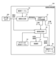
- FIG. 2 is a functional block diagram illustrating functions of the image forming apparatus according to the first embodiment.
- FIG. 11 is a functional block diagram showing functions of an image forming apparatus according to a second embodiment.
- FIG. 11 is a functional block diagram showing functions of an image forming apparatus according to a third embodiment.
- FIG. 1 is a block diagram illustrating the concept of performing either a learning process or an inference process, or both. 1 is an explanatory diagram showing a schematic hardware configuration of an image forming apparatus according to an embodiment of the present invention;
- FIG. 2 is an explanatory diagram showing a schematic hardware configuration of an edge device according to the present embodiment.
- FIG. 13 is a diagram showing a concept when a temperature range is set as a parameter for humans.
- An explanatory diagram (part 2) showing the concept of an image forming apparatus according to the second embodiment creating an augmented image to be used as an input image in object recognition processing using a machine learning model.
- An explanatory diagram (part 3) showing the concept of an image forming apparatus according to the second embodiment creating an augmented image to be used as an input image in object recognition processing using a machine learning model.
- An explanatory diagram (part 4) showing the concept of an image forming apparatus according to the second embodiment creating an augmented image to be used as an input image in object recognition processing using a machine learning model.
- FIG. 13 is a diagram showing a concept when a temperature range is set as a parameter for a vehicle outdoors in summer.
- An explanatory diagram (part 5) showing the concept of an image forming apparatus according to the second embodiment creating an augmented image to be used as an input image in object recognition processing using a machine learning model.
- An explanatory diagram (part 6) showing the concept of an image forming apparatus according to the second embodiment creating an augmented image to be used as an input image in object recognition processing using a machine learning model.
- An explanatory diagram (part 7) showing the concept of an image forming apparatus according to the second embodiment creating an augmented image to be used as an input image in object recognition processing using a machine learning model.
- FIG. 8 is an explanatory diagram showing the concept of an image forming apparatus according to the second embodiment creating an augmented image to be used as an input image in object recognition processing using a machine learning model.
- FIG. 13 is a diagram showing a concept when a temperature range is set as a parameter for a vehicle outdoors in winter.
- 1 shows an infrared image of an indoor area showing hot equipment as a target.
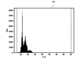
- 10B shows a histogram of the infrared image of FIG. 10A.
- 10B shows an expanded image in which the target temperature range of the infrared image of FIG. 10A has been normalized to approximately 20° C. to approximately 50° C.
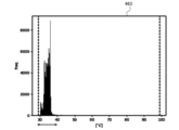
- the histogram shows the target temperature range of FIG. 10B normalized to approximately 18° C. to approximately 55° C.
- 1 shows an infrared image taken outdoors, with hot spots on a vehicle object displayed in the area.
- 11B shows a histogram of the infrared image of FIG. 11A.
- FIG. 11B shows an expanded image in which the target temperature range of the infrared image of FIG. 11A has been normalized to approximately 30° C. to approximately 42° C.
- the histogram shows the target temperature range of FIG. 11B normalized to approximately 30° C. to approximately 44° C. 1 shows an infrared image of a cold outdoor environment with hot spots on a vehicle object visible in the area.
- 12B shows a histogram of the infrared image of FIG. 12A.
- 12B shows an expanded image in which the target temperature range of the infrared image of FIG. 12A has been normalized to approximately 10° C. to approximately 31° C.
- the histogram shows the target range of temperatures in FIG. 12B normalized to approximately 9° C. to approximately 33° C.
- FIG. 12B shows an expanded image in which the target temperature range of the infrared image of FIG. 11A has been normalized to approximately 30° C. to approximately 42° C.
- the histogram shows the target temperature range of FIG. 11
- FIG. 11 is an explanatory diagram (part 1) showing an example in which the image expansion unit of the image forming apparatus according to the third embodiment generates an infrared image within a rectangle with contrast added in an image area in which a specific object is present.
- FIG. 13 is an explanatory diagram (part 2) showing an example in which the image expansion unit of the image forming apparatus according to the third embodiment generates an infrared image within a rectangle with contrast in an image area in which a specific object is present.
- FIG. 11 is an explanatory diagram (part 3) showing an example in which the image expansion unit of the image forming apparatus according to the third embodiment generates an infrared image within a rectangle with contrast in an image area in which a specific object is present.
- First Embodiment is a functional block diagram showing functions of an image processing device 100 according to the first embodiment.
- the image processing device 100 is a device that generates and processes infrared images, and is connected to an infrared camera 300. Note that the image processing device 100 of the first embodiment processes infrared images by targeting an object to be learned, and generates a combination of an augmented image and ground truth data to be used for machine learning.
- the infrared camera 300 is a camera for visualizing infrared rays emitted from an object.
- the infrared camera 300 detects the temperature of the object as an infrared detection signal and sends it to the image processing device 100.
- the image processing device 100 is configured with an image generation unit 10, a standard table 20, an image expansion unit 40, a correct answer data generation processing unit 31 (identification unit), an object-specific table 50, and a learning data database 60.
- the image generating unit 10 generates an infrared image (hereinafter also referred to as a standard image) based on the infrared detection signal acquired from the infrared camera 300 while referring to the standard table 20.
- the image generating unit 10 can generate an infrared image from the infrared detection signal obtained by capturing an image of an object with the infrared camera 300.
- the standard table 20 stores parameters that the image generating unit 10 references when generating a standard image.
- the correct data generation processing unit 31 performs object recognition processing on the generated infrared image to detect objects.
- the correct data generation processing unit 31 sets a label of the detected object in the generated infrared image. In this case, the correct data generation processing unit 31 sets a label as correct data to the object in the infrared image.
- the correct data generation processing unit 31 can also set a rectangle indicating the area of the detected object.
- the rectangle indicating the area of the object is set in the image area where the specific object exists.
- the correct data generation processing unit 31 may set the label settings and rectangle manually or automatically. This allows the correct data generation processing unit 31 to identify the image area where the specific object exists based on the infrared image generated by the image generation unit 10.
- the image expansion unit 40 When used during machine learning, the image expansion unit 40 according to the first embodiment creates an expanded image to be used as learning data for creating a machine learning model based on information about the object in the object-specific table 50 from an infrared detection signal obtained by capturing an image of the object.
- the image expansion unit 40 When creating an expanded image, the image expansion unit 40 imparts a predetermined contrast to the range of infrared information in which a specific object may exist.
- the image expansion unit 40 imparts a predetermined contrast by allocating the range of infrared information in which a specific object may exist to a predetermined brightness range (e.g., from 32 to 233).
- a predetermined brightness range e.g., from 32 to 233.
- the range of infrared information in which a person may exist refers to infrared information corresponding to a range of 10°C to 40°C, for example.
- the range of infrared information in which a vehicle may exist refers to infrared information corresponding to a range of 10°C to 70°C, for example. This allows for emphasis processing of the appearance level of the object, thereby improving the object detection performance by the machine learning model.
- the image extension unit 40 may generate a plurality of extended images, each of which is given a different contrast to the range of infrared information in which a specific object may exist.
- the image extension unit 40 assigns the range of infrared information in which a specific object may exist to a plurality of brightness ranges (e.g., from 32 to 223 and from 64 to 191), thereby giving each of the ranges a different contrast.
- the image extension unit 40 allows the image extension unit 40 to generate multiple extended images that gradually enhance the object. For example, if the object is a vehicle, it is possible to extend the image variations to correspond to daytime and nighttime, and sunny and stormy weather. By applying machine learning to these multiple extended images, it is possible to improve the object detection performance.
- the image expansion unit 40 may add a predetermined contrast to an image area in which a specific object is present. That is, the image expansion unit 40 obtains the minimum and maximum detection signal values of the image area in which a specific object is present, and assigns the minimum detection signal value to a luminance signal of 0 and the maximum detection signal value to a luminance signal of 255. This enables data expansion targeted at the object.
- the image extension unit 40 may set the outside of the image area where a specific object exists as a background image and impart a different contrast to the background image. That is, the image extension unit 40 acquires the maximum and minimum values of the detection signal of this background image, and assigns the minimum value of the detection signal to the luminance signal of 64, and the maximum value of the detection signal to the luminance signal of 191. Furthermore, the image extension unit 40 may add a predetermined noise when creating the extended image. This can improve the robustness of the machine learning model that has learned the extended image.
- the object-specific table 50 stores parameters that the image extension unit 40 references when generating an extended image. These parameters include, for example, information about the temperature of the object when generating the extended image, and temperature information related to the climate and season. Specifically, the object-specific table 50 corresponds to a temperature range for processing to highlight the object and processing to enhance variation.
- the object can be a living thing such as a person or an animal, or it can be an object (solid) that has a specific temperature, such as a vehicle.
- multiple augmented images are generated for the range of infrared information where a specific object may exist. This is to reduce the cost of data collection and to increase the variation of situations that cannot actually be photographed through image processing. This increases the robustness of the machine learning model so that it can make inferences with better performance.
- the input image is processed by adding a predetermined contrast to a predetermined temperature range of the infrared image to make it easier for the machine learning model to detect the target.
- Second Embodiment 2 is a functional block diagram showing functions of an image processing device 100 according to the second embodiment.
- the image processing device 100 according to the second embodiment differs from the image processing device 100 according to the first embodiment in that the image extension unit 40 has a different function, that an inference unit 70 is provided instead of the learning data database 60, and that a supervised data generation processing unit 31 outputs a rectangle indicating an image area of an object and label data indicating information about the object.
- the rest of the configuration is the same as in the first embodiment, so a detailed explanation will be omitted.
- the second embodiment is designed to create more optimal images and improve inference capabilities, even in scenes where infrared characteristics make it difficult to see.
- the image extension unit 40 outputs the generated extended image to the inference unit 70.
- the inference unit 70 uses this extended image as an input image and executes object recognition processing using a machine learning model.
- the image expansion unit 40 When generating an input image used by the inference unit 70 in the process of recognizing an object, the image expansion unit 40 imparts a predetermined contrast to the range of infrared information in which a specific object may exist. In addition, when generating an input image used by the inference unit 70 in the process of recognizing an object, the image expansion unit 40 may impart a predetermined contrast to an image region in which a specific object exists.
- the correct answer data generation processing unit 31 outputs label data as correct answer data indicating the target object.
- the correct answer data generation processing unit 31 also outputs a rectangle indicating the image area of the target object.
- the image expansion unit 40 may perform processing to refine the image within a specific rectangle.
- the rectangle may be generated using the results of object recognition processing that uses as input a visible light image captured simultaneously with a visible light camera (not shown).
- the image extension unit 40 references the object-specific table 50 based on the detection signal from the infrared camera 300 and the rectangle information from the ground-truth data generation processing unit 31, and generates an input image with contrast. This allows the image extension unit 40 to refine the input image.
- the image expansion unit 40 can impart a predetermined contrast to the range of infrared information in which a specific object may exist. Also, when generating an input image to be used in the process of recognizing an object, the image expansion unit 40 may impart a predetermined contrast to an image region in which a specific object exists. Furthermore, the image expansion unit 40 may thin out information in a range of infrared information in which a specific object may not exist. Specifically, the image expansion unit 40 may thin out information in a temperature range in which a specific object may not exist.
- the inference unit 70 performs inference using the input image generated by the image extension unit 40. This allows the image extension unit 40 to create a more optimal image even in scenes where infrared characteristics are difficult to achieve, improving the inference capabilities of the inference unit 70.
- Third Embodiment 3 is a functional block diagram showing functions of an image processing device 100 according to the third embodiment.
- the image processing device 100 according to the third embodiment is a device equipped with the machine learning functions according to the first embodiment and the inference functions according to the second embodiment, and is configured to include a supervised data generation processing unit 31, an image extension unit 40, a learning data database 60, and an inference unit 70.
- Figure 4 is a block diagram showing the concept of performing either the learning process or the inference process, or both.
- the image processing device 150 is configured to include a learning data database 60, a learning process unit 110, and an inference model 120.
- the learning process unit 110 includes a data extension unit 111.
- the learning process unit 110 performs machine learning using the learning data (e.g., standard images and augmented images) stored in the learning data database 60.
- learning data e.g., standard images and augmented images
- the data expansion unit 111 expands the variation of the learning data to improve the robustness of the inference model. That is, the data expansion unit 111 generates an expanded image (variation image) from a standard image using the function shown in the image expansion unit 40 in FIG. 1. This allows the learning process unit 110 to perform machine learning by artificially increasing the variation of infrared images.
- the inference model 120 is the result of machine learning of the augmented image and the variation image in the learning process unit 110. By applying this inference model 120 to the inference process unit 210 of the edge device 200, it is possible to detect objects with improved performance of the machine learning model.
- the edge device 200 is configured with an inference process unit 210 and an inference model 120.
- the inference process unit 210 has a data processing unit 211.
- the inference process unit 210 performs inference on the input data 280 using the inference model 120.
- the data processing unit 211 processes the input image to detect the object with better performance. That is, the data processing unit 211 generates an input image with contrast for the input data 280 using the function shown in the image expansion unit 40 in FIG. 2. This allows the inference process unit 210 to lower the difficulty of recognizing the object and improve the recognition performance. Therefore, the inference process unit 210 can improve the recognition result 290.
- the inference process unit 210 may detect the movement of an object based on the position of a label or a rectangle in the input data 280. For example, the inference process unit 210 can output the movement direction when an object moves from right to left in the input data 280 as the authentication result 290.
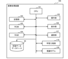
- FIG. 5 is an explanatory diagram showing a schematic hardware configuration of the image processing device 100 according to this embodiment.
- the image processing device 100 is configured with a CPU (Central Processing Unit) 101, a memory unit 102, a ROM (Read Only Memory) 103, a RAM (Random Access Memory) 104, an operation unit 105, a display unit 106, a communication unit 107, a learning data database 60, a learning process unit 110, and an inference model 120.
- a CPU Central Processing Unit
- a memory unit 102 a memory unit 102
- ROM Read Only Memory
- RAM Random Access Memory
- the CPU 101 reads out and executes a program from the memory unit 102 or the ROM 103, thereby realizing the learning process unit 110 and the inference model 120, and controlling the overall operation of the image processing device 100. At this time, various data stored in the memory unit 102 is referenced.
- the memory unit 102 is composed of a large-capacity storage medium such as a semiconductor memory or a hard disk drive, and constitutes the standard table 20 and the object-specific table 50.
- the CPU 101 transmits and receives various data to and from external devices connected to a communication network such as a LAN (Local Area Network) or a WAN (Wide Area Network) via the communication unit 107.
- the CPU 101 receives, for example, a detection signal transmitted from an infrared camera 300, and generates an infrared image based on this detection signal using the image generation unit 10 (see Figure 1).
- the communication unit 107 is composed of a communication control card such as a NIC (Network Interface Card).
- a communication control card such as a NIC (Network Interface Card).
- the operation unit 105 includes various operation keys such as a numeric keypad and a start key.
- the operation unit 105 accepts various input operations by the user and outputs operation signals to the CPU 101.
- the display unit 106 is, for example, a liquid crystal display, and displays characters, figures, images, etc.
- FIG. 6 is an explanatory diagram showing a schematic hardware configuration of the edge device 200 according to this embodiment.
- the edge device 200 is configured with a CPU 201, a memory unit 202, a ROM 203, a RAM 204, an inference process unit 210, and an inference model 120.
- the CPU 201 implements the inference process unit 210 and the inference model 120 by reading and executing a program from the memory unit 202 or the ROM 203, and controls the overall operation of the edge device 200.
- the inference model 120 of the edge device 200 is the inference model 120 of the image processing device 100 shown in Figures 4 and 5, and references various data stored in the memory unit 202.
- the memory unit 202 is composed of a large-capacity storage medium such as a semiconductor memory or a hard disk drive, and constitutes an object-specific table 50.
- FIGS 7A to 7H are explanatory diagrams showing the concept of the image processing device 100 according to the first embodiment creating an augmented image to be used as learning data for creating a machine learning model based on information about an object from an infrared image captured by an infrared camera 300.
- the image expansion unit 40 of the image processing device 100 refers to the object-specific table 50, changes the target range including the focus range, and generates eight expanded images from a predetermined infrared detection signal. In other words, the image expansion unit 40 changes the dynamic range to generate expanded images in which the range in which the target can be expressed in black and white has been changed.
- the image extension unit 40 sets the temperature range of 31°C to 41°C, which corresponds to body temperature, as the priority range 79 from the object-specific table 50, for example, for humans, who are warm-blooded animals.
- the image extension unit 40 then generates eight extended images 71-78 that include the temperature range of 31°C to 41°C as the priority range.
- FIG. 7A shows an expanded image 71 generated with the temperature parameter set in the range from 5° C. to 40° C.
- the image extension unit 40 assigns a brightness value of 0 to pixels whose infrared detection signal is 5° C. or less, and assigns a brightness value of 255 to pixels whose infrared detection signal is 40° C. or more.
- the image extension unit 40 also assigns proportional brightness values to pixels whose infrared detection signal is between 5° C. and 40° C.
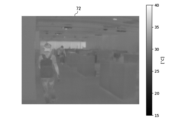
- FIG. 7B shows an expanded image 72 generated with the temperature parameter set in the range from 15° C. to 40° C.
- the image extension unit 40 assigns a brightness value of 0 to pixels whose infrared detection signal is 15° C. or less, and assigns a brightness value of 255 to pixels whose infrared detection signal is 40° C. or more.
- the image extension unit 40 also assigns proportional brightness values to pixels whose infrared detection signal is between 15° C. and 40° C.
- FIG. 7C shows an expanded image 73 generated with the temperature parameter set in the range from 20° C. to 40° C.
- the image extension unit 40 assigns a brightness value of 0 to pixels whose infrared detection signal is 20° C. or less, and assigns a brightness value of 255 to pixels whose infrared detection signal is 40° C. or more.
- the image extension unit 40 also assigns proportional brightness values to pixels whose infrared detection signal is between 20° C. and 40° C.
- FIG. 7D shows an expanded image 74 generated with the temperature parameter set in the range from 28° C. to 40° C.
- the image extension unit 40 assigns a brightness value of 0 to pixels whose infrared detection signal is 28° C. or less, and assigns a brightness value of 255 to pixels whose infrared detection signal is 40° C. or more.
- the image extension unit 40 also assigns proportional brightness values to pixels whose infrared detection signal is between 28° C. and 40° C.
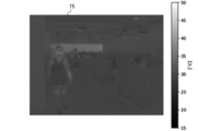
- FIG. 7E shows an expanded image 75 generated with the temperature parameter set in the range from 15° C. to 50° C.
- the image extension unit 40 assigns a brightness value of 0 to pixels whose infrared detection signal is 15° C. or less, and assigns a brightness value of 255 to pixels whose infrared detection signal is 50° C. or more.
- the image extension unit 40 also assigns proportional brightness values to pixels whose infrared detection signal is between 15° C. and 50° C.
- FIG. 7F shows an expanded image 76 generated with the temperature parameter set in the range of 20° C. to 50° C.
- the image extension unit 40 assigns a brightness value of 0 to pixels whose infrared detection signal is 20° C. or less, and assigns a brightness value of 255 to pixels whose infrared detection signal is 50° C. or more.
- the image extension unit 40 also assigns proportional brightness values to pixels whose infrared detection signal is between 20° C. and 50° C.
- FIG. 7G shows an expanded image 77 generated with the temperature parameter set in the range from 25° C. to 50° C.
- the image extension unit 40 assigns a brightness value of 0 to pixels whose infrared detection signal is 25° C. or less, and assigns a brightness value of 255 to pixels whose infrared detection signal is 50° C. or more.
- the image extension unit 40 also assigns proportional brightness values to pixels whose infrared detection signal is between 25° C. and 50° C.
- FIG. 7H shows an expanded image 78 generated with the temperature parameter set to a range of 25° C. to 40° C.
- the image extension unit 40 assigns a brightness value of 0 to pixels whose infrared detection signal is 25° C. or less, and assigns a brightness value of 255 to pixels whose infrared detection signal is 40° C. or more.
- the image extension unit 40 also assigns proportional brightness values to pixels whose infrared detection signal is between 25° C. and 40° C.
- Figure 7I shows the concept of the temperature parameters in Figures 7A through 7H when displayed over a temperature range.
- Figures 7A to 7H include the focus range 79, and augmented images (variation images) with diverse appearances are generated within the visible dynamic range without compromising the temperature range in which the object appears. Also, in Figures 7A to 7H, the entire range of the image is processed, so augmented images 71 to 78 are generated that have been processed for both the foreground and background.
- Figures 8A to 8E and Figures 9A to 9E are explanatory diagrams showing the concept of the image processing device 100 according to the second embodiment creating an augmented image to be used as an input image in object recognition processing using a machine learning model.
- the image extension unit 40 of the image processing device 100 refers to the object-specific table 50, changes the target range including the priority range 89, and generates an input image with improved visibility of the target. In other words, the image extension unit 40 changes the dynamic range to generate an input image (extended images 81-84, 91-94) that corresponds to the situation of the operating environment.
- the image extension unit 40 adjusts the dynamic range by setting the temperature range of about 35°C to about 53°C, which corresponds to the temperature of a vehicle, as the priority range 89 from the object-specific table 50, for example, targeting a high-temperature vehicle.
- the image extension unit 40 adjusts the dynamic range as the target range depending on whether the vehicle is installed outdoors or indoors, or on the seasonal environment.
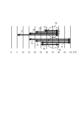
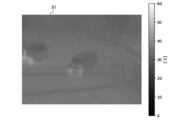
- FIG. 8A shows an augmented image 81 generated outdoors in summer with the temperature parameter set to a range from 0° C. to 60° C.
- FIG. 8B shows an augmented image 82 generated outdoors in summer with the temperature parameter set to a range from 10° C. to 60° C.
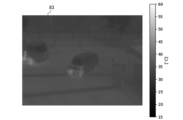
- FIG. 8C shows an augmented image 83 generated outdoors in summer with the temperature parameter set to a range from 15° C. to 60° C.
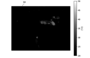
- FIG. 8D shows an augmented image 84 generated outdoors in summer with the temperature parameter set to a range from 20° C. to 60° C.
- FIG. 8E shows a concept when the temperature parameters of FIG. 8A to FIG. 8D are set within a temperature range for a vehicle outdoors in summer.
- the extended images 81 to 84 include a priority range 89, and the visible dynamic range is adjusted.
- the low temperatures are raised to cover the high temperature range, with the upper limit being 60°C.
- the priority range 89 is also adjusted to be from approximately 35°C to approximately 52°C.
- extended image 81 is not suitable as an input image because it has low contrast.
- extended image 84 is suitable as an input image because it has high contrast and emphasized edges.
- FIG. 9A shows an augmented image 91 generated outdoors in winter with the temperature parameter set to a range from 0° C. to 50° C.
- FIG. 9B shows an augmented image 92 generated outdoors in winter with the temperature parameter set to a range of 10° C. to 50° C.
- FIG. 9C shows an augmented image 93 generated outdoors in winter with the temperature parameter set to a range of 15° C. to 50° C.
- FIG. 9D shows an augmented image 94 generated outdoors in winter with the temperature parameter set to a range of 20° C. to 50° C.
- FIG. 9E shows a concept when the temperature parameters of FIG. 9A to FIG. 9D are set within a temperature range for a vehicle outdoors in winter.
- extended images 91 to 94 include a priority range 89, and the visible dynamic range is adjusted.
- the high temperature side is lowered and the upper limit is set to 50°C to cover the low temperature range.
- the priority range 89 is also adjusted to be between approximately 30°C and approximately 43°C.
- the extended image 94 is not suitable as an input image because it has low contrast.
- the extended image 92 is suitable as an input image because it has high contrast and emphasized edges.
- FIGS. 10A to 10D are explanatory diagrams showing an example in which the image processing device 100 according to the third embodiment adjusts the target range using percentiles and detects an object when generating an extended image indoors.
- percentiles are a method of normalizing the distribution of measured values by sorting them from smallest to largest numbers and displaying them as a percentage, thereby determining where the measured values fall when sorted from smallest to largest numbers.
- the image expansion unit 40 of the third embodiment rearranges the infrared detection signals for each pixel, and sets the target range between percentiles X and Y.
- percentile 10% to 90% means that the target range is from the smallest number in the distribution of measurement values, 10% to 90%.
- the image expansion unit 40 of the image processing device 100 uses a histogram of the infrared detection signal to normalize the target range to percentiles X to Y. This removes outliers below X% and above Y%, improving visibility.
- FIG. 10A shows an infrared image 450 in which a high-temperature device is displayed as an object in area 400 indoors.
- the infrared image 450 in FIG. 10A shows a temperature range from approximately 20°C to approximately 140°C.
- FIG. 10B shows a histogram 453 of the infrared image 450 of FIG. 10A.
- the horizontal axis shows temperature [°C]
- the vertical axis shows frequency [freq].
- the frequency of the detection signal is high in the range of about 18 [°C] to about 30 [°C]. Therefore, the image extension unit 40 can improve the visibility of the infrared image by adjusting the infrared image 450 to the target range of percentiles X to Y.
- FIG. 10C shows an expanded image 451 in which the target temperature range of the infrared image 450 in FIG. 10A has been normalized to approximately 20°C to approximately 55°C.
- specific objects are displayed in areas 400, 401, and 402.
- Area 400 displays a person carrying high-temperature equipment
- area 401 displays a person carrying luggage
- area 402 displays a person standing in front of a shower room.
- FIG. 10D shows a histogram 454 in which the target temperature range of FIG. 10B has been normalized to approximately 18°C to approximately 55°C.
- the image extension unit 40 creates a histogram of the detection signal and adjusts the target temperature range with percentiles X to Y. This makes it possible to remove outliers below X% and above Y%, so that information about the object that would be buried with simple normalization can be easily viewed.
- the percentile values X to Y are the parameter width.
- the image extension unit 40 can increase the variety of extended images used in machine learning by setting the parameter width randomly or in a brute force manner. Furthermore, during inference, the image extension unit 40 can set Y, which is the upper limit value of the parameter width, low, making it easier to detect objects with relatively low temperatures, for example, in an environment where high-temperature equipment is installed. In this way, the image extension unit 40 can adjust the temperature range of the target range according to the parameter width.
- FIGS. 11A to 11D are explanatory diagrams showing an example in which the image processing device 100 according to the third embodiment uses percentiles to adjust the target range and detect the target when generating an extended image outdoors.
- the image expansion unit 40 of the image processing device 100 also uses a histogram of the infrared detection signal outdoors to normalize the target range to percentiles X to Y. This removes outliers below X% and above Y%, improving visibility.
- FIG. 11A shows an infrared image 460 taken outdoors, in which a high-temperature part of a vehicle, which is an object, is displayed in area 410.
- the infrared image 460 in FIG. 11A shows a temperature range of approximately 30°C to approximately 100°C.
- FIG. 11B shows a histogram 463 of the infrared image of FIG. 11A.
- the horizontal axis shows temperature [°C]
- the vertical axis shows frequency [freq].
- the frequency of the detection signal is high in the range of about 30 [°C] to about 40 [°C]. Therefore, the image extension unit 40 can improve the visibility of the infrared image by adjusting the infrared image 460 to the target range of percentiles X to Y.
- FIG. 11C shows an augmented image 461 in which the target temperature range of the infrared image 460 in FIG. 11A has been normalized to approximately 30° C. to approximately 44° C.
- a specific target is displayed in an area 410.
- the engine part of a garbage truck is displayed in the area 410.
- FIG. 11D shows a histogram 464 in which the target temperature range of FIG. 11B has been normalized to approximately 30° C. to approximately 44° C.
- the image expansion unit 40 creates a histogram of the detection signal, even when it is outdoors, and adjusts the target temperature range with percentiles X to Y. This makes it possible to remove outliers below X% and above Y%, so that information about the object that would be buried with simple normalization can be easily viewed.
- FIGS. 12A to 12D are explanatory diagrams showing an example in which the image processing device 100 according to the third embodiment uses percentiles to adjust the target range and detect objects when generating an extended image in cold outdoor conditions.
- the image expansion unit 40 of the image processing device 100 uses a histogram of the infrared detection signal to normalize it in the range of percentiles X to Y, even in cold outdoor conditions. This makes it possible to remove outliers below X% and above Y%, improving visibility.
- FIG. 12A shows an infrared image 470 in which the hot part of the target vehicle is displayed in area 420 in a cold outdoor environment.
- the infrared image 470 in FIG. 12A shows a temperature range of approximately 10°C to approximately 90°C.
- FIG. 12B shows a histogram 473 of the infrared image of FIG. 12A.
- the horizontal axis shows temperature [°C]
- the vertical axis shows frequency [freq].
- the frequency of the detection signal increases in the range from approximately 10 [°C] to approximately 25 [°C].
- FIG. 12C shows an expanded image 471 in which the temperature range of the infrared image 470 in FIG. 12A has been normalized to a target range of approximately 10°C to approximately 35°C.
- specific objects are visible in areas 420, 421, and 422.
- a traveling vehicle is visible in area 420
- an oncoming vehicle is visible in area 421
- a pedestrian is visible in area 422.
- FIG. 12D shows a histogram 474 in which the target temperature range of FIG. 12B has been normalized to approximately 9°C to approximately 33°C.
- the image extension unit 40 uses the histogram of the infrared detection signal to change and normalize the target range of the temperature of the infrared image 470 in FIG. 12A within the range of percentiles X to Y. Similarly, even in the case of cold outdoor conditions, the image extension unit 40 can remove outliers below X% and above Y% by adjusting the target range within the range of percentiles X to Y, making it easy to view information about the object that would be buried with simple normalization.
- the image extension unit 40 of the image processing device 100 When creating an infrared image, the image extension unit 40 of the image processing device 100 according to the third embodiment imparts a predetermined contrast to an image region in which a specific object exists.
- the image extension unit 40 may generate a plurality of infrared images by using the outside of the image region as a background image and imparting different contrasts to the background images.
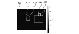
- FIGS. 13A to 13C are explanatory diagrams showing an example in which the image expansion unit 40 of the image processing device 100 according to the third embodiment generates an infrared image within a rectangle with a predetermined contrast added to an image area in which a specific object is present.
- the image expansion unit 40 sets correct rectangles 430-433 of the object in the infrared image 480. Because the image processing device 100 includes a correct data generation processing unit 31, the image expansion unit 40 can set rectangles as correct data (referred to as correct rectangles) by the correct data generation processing unit 31. Note that the target temperature range of the infrared image 480 is set to approximately -10°C to approximately 100°C.
- the image expansion unit 40 references the object-specific table 50 to generate an expanded image 481 (infrared image) within a rectangle that adds a predetermined contrast to the image area where a specific object is present.
- the image extension unit 40 adjusts the target temperature range of the infrared image 480 from approximately -12.5°C to approximately 8°C so that the extended image 481 of the important range in the correct answer rectangles 430-433 is displayed appropriately.
- the image extension unit 40 generates an extended image 481 with a predetermined contrast in the correct answer rectangles 430-433 by appropriately setting the target temperature range.
- the image extension unit 40 sets a target temperature range, or sets a temperature range based on a specified percentile range, and generates an extended image 481 with contrast. This allows the image extension unit 40 to generate an extended image 481 in which a temperature range corresponding to the target object in the correct rectangles 430 to 433 is set by referencing the object-specific table 50.
- the image extension unit 40 generates an extended image by combining extended image 481, in which contrast is added to answer rectangles 430-433, with extended image 482, in which various temperature ranges are set as the background image.
- the image extension unit 40 can set the outside of the rectangle as the background image and generate extended image 482, in which multiple temperature ranges are set for the background image.
- the image extension unit 40 can combine the extended image 481 in the contrasted answer rectangles 430-433 with the extended image 482 as a background image with various variations, thereby generating various extended images to be used in machine learning.
- the image processing device 100 is configured to include the image extension unit 40.
- the image extension unit 40 creates an extended image to be used as learning data for creating a machine learning model from an infrared image of an object based on information about the object in the standard table 20.
- the image processing device 100 according to the first embodiment can use an infrared image of an object to create an augmented image to be used as learning data for creating a machine learning model, based on information about the object. Therefore, the image processing device 100 according to the first embodiment can increase the variety of learning data.
- the image processing device 100 according to the first embodiment may impart a predetermined contrast to the range of infrared information in which a specific object may exist when creating an extended image using the image extension unit 40.
- the image processing device 100 according to the first embodiment may generate a plurality of infrared images in which different contrasts are imparted to the range of infrared information in which a specific object may exist when creating an infrared image using the image extension unit 40.
- the image processing device 100 is also configured to include an image extension unit 40.
- the image extension unit 40 creates an extended image to be used as an input image in the object recognition process using a machine learning model.
- the image processing device 100 according to the second embodiment can create an augmented image to be used as an input image in the object recognition process using a machine learning model by referring to the object-specific table 50. Therefore, the image processing device 100 according to the second embodiment can refine the input image used in inference, and can improve the object detection performance in infrared images.
- the image processing device 100 according to the second embodiment may impart a predetermined contrast to a range of infrared information in which a specific object may exist when generating an input image to be used in the process of recognizing an object by the image expansion unit 40.
- the image processing device 100 according to the second embodiment may impart contrast to an image region in which a specific object exists when generating an input image to be used in the process of recognizing an object by the image expansion unit 40.
- the image processing device 100 is also configured with an image extension unit 40, a learning data database 60, and an inference unit 70.
- the image processing device 100 according to the third embodiment is a device that combines the image processing device 100 according to the first embodiment and the image processing device 100 according to the second embodiment.
- the image processing device 100 according to the third embodiment may impart a predetermined contrast to an image area in which a specific object is present when creating an infrared image using the image expansion unit 40.
- the image processing device 100 according to the third embodiment may use the image area outside the image area as a background image when creating an infrared image using the image expansion unit 40, and may impart a different contrast to each of the background images.
- the object in the first to third embodiments may be a solid having a specific temperature, such as a human being, a pet, a warm-blooded animal such as livestock, or a vehicle.
- the information about the object in the first to third embodiments may be a temperature range in which a specific object may exist.
- the object information in the first to third embodiments may be an image area in which a specific object is present.
- the image processing device 100 may further include a learning process unit 110 that performs machine learning using learning data.
- the edge device 200 may include an inference model 120 trained by machine learning using an image processing device 100 that includes an image expansion unit 40 that creates an expanded image based on information about an infrared image of an object, either to be used as learning data for creating a machine learning model or to be used as an input image in object recognition processing using a machine learning model, and a learning process unit 110 that performs machine learning using the learning data, and an inference process unit 210 that applies the expanded image created by the image expansion unit 40 to the inference model 120 to infer the object.
- an image processing device 100 that includes an image expansion unit 40 that creates an expanded image based on information about an infrared image of an object, either to be used as learning data for creating a machine learning model or to be used as an input image in object recognition processing using a machine learning model, and a learning process unit 110 that performs machine learning using the learning data, and an inference process unit 210 that applies the expanded image created by the image expansion unit 40 to the inference model 120 to infer the object.
- the edge device 200 includes an inference process unit 210 and an inference model 120.
- the inference process unit 210 includes a data processing unit 211, and generates an input image with contrast from the input data 280 using the function shown in the image expansion unit 40 in FIG. 2. As a result, the inference process unit 210 performs inference on the input image with contrast using the inference model 120.
- the inference model 120 is a model that has been machine-learned by an image processing device 100 that includes an image expansion unit 40 that creates an expanded image based on information about an object captured in an infrared image of the object, either to be used as learning data for creating a machine learning model or to be used as an input image in the object recognition process by the machine learning model, and a learning process unit 110 that performs machine learning using the learning data.
- the edge device 200 is equipped with an inference process unit 210 and an inference model 120, thereby enabling the object detection performance in infrared images to be improved.
- Image generation unit 20 Standard table 31 Correct data generation processing unit (identification unit) 40 Image expansion unit 50 Object specific table 60 Learning data database 70 Inference unit 100, 150 Image processing device 110 Learning process unit 111 Data expansion unit 120 Inference model 200 Edge device 210 Inference process unit 211 Data processing unit 280 Input data 290 Recognition result 300 Infrared camera
Landscapes
- Engineering & Computer Science (AREA)
- Theoretical Computer Science (AREA)
- Computer Vision & Pattern Recognition (AREA)
- Physics & Mathematics (AREA)
- General Physics & Mathematics (AREA)
- Artificial Intelligence (AREA)
- Health & Medical Sciences (AREA)
- Computing Systems (AREA)
- Databases & Information Systems (AREA)
- Evolutionary Computation (AREA)
- General Health & Medical Sciences (AREA)
- Medical Informatics (AREA)
- Software Systems (AREA)
- Multimedia (AREA)
- Image Processing (AREA)
Abstract
Description
(1) 対象物を撮像した赤外線の検知信号から、前記対象物の情報に基づいて、機械学習モデル作成のための学習データとして使用するか、または、前記機械学習モデルによる前記対象物の認識処理における入力画像として使用する拡張画像を作成する画像拡張部、
を備える画像処理装置。
(1)に記載の画像処理装置。
(1)に記載の画像処理装置。
(1)に記載の画像処理装置。
前記拡張画像を作成する際、特定の対象物が存在し得る赤外線情報の範囲に、所定のコントラストを付与する、
(1)に記載の画像処理装置。
特定の対象物が存在し得る赤外線情報の範囲に、それぞれ異なるコントラストが付与された複数の拡張画像を生成する、
(1)に記載の画像処理装置。
前記赤外線画像に基づいて特定の対象物が存在する画像領域を特定する特定部と、
を更に備え、
前記画像拡張部は、
前記拡張画像を作成する際、特定の対象物が存在する画像領域に所定のコントラストを付与する、
(1)に記載の画像処理装置。
前記拡張画像を作成する際、前記画像領域の外部を背景画像とし、当該背景画像にそれぞれ異なるコントラストを付与する、
(7)に記載の画像処理装置。
(1)に記載の画像処理装置。
前記対象物を認識する処理で使用する入力画像を生成する際、特定の対象物が存在し得る赤外線情報の範囲に、所定のコントラストを付与する、
(1)に記載の画像処理装置。
前記対象物を認識する処理で使用する入力画像を生成する際、特定の対象物が存在する画像領域に所定のコントラストを付与する、
(7)に記載の画像処理装置。
前記学習データを用いて、機械学習する学習工程部と、を備える画像処理装置で機械学習した推論モデルと、
前記画像拡張部において作成された前記拡張画像を、前記推論モデルに適用して、前記対象物を推論する推論工程部と、
を備えるエッジデバイス。
を含む画像生成方法。
をコンピュータに実行させるための画像生成プログラム。
[画像処理装置の全体構成]
図1は、第1実施形態に係る画像処理装置100の機能を示した機能ブロック図である。画像処理装置100は、赤外線画像を生成し加工する装置であり、赤外線カメラ300に接続されている。なお、第1実施形態の画像処理装置100は、学習させたい対象物を狙って赤外線画像の加工を行い、機械学習に使用する拡張画像と正解データの組み合わせを生成する。
図2は、第2実施形態に係る画像処理装置100の機能を示した機能ブロック図である。第2実施形態の画像処理装置100が第1実施形態の画像処理装置100と異なる点は、画像拡張部40の機能が異なる点と、学習データデータベース60の代わりに、推論部70を備えている点と、正解データ生成処理部31が対象物の画像領域を示す矩形と、対象物の情報を示すラベルデータを出力することである。
図3は、第3実施形態に係る画像処理装置100の機能を示した機能ブロック図である。第3実施形態の画像処理装置100は、第1実施形態に係る機械学習時の機能と、第2実施形態に係る推論時の機能と、を備えた装置であり、正解データ生成処理部31、画像拡張部40、学習データデータベース60、および推論部70を備えて構成されている。
図5は、本実施形態に係る画像処理装置100の概略のハードウェア構成を示した説明図である。
図6は、本実施形態に係るエッジデバイス200の概略のハードウェア構成を示した説明図である。
[画像形成装置の機械学習時(第1実施形態)]
次に、第1実施形態に係る画像処理装置100の画像拡張部40の処理を説明する。
図7Aから図7Hは、第1実施形態に係る画像処理装置100が、赤外線カメラ300で対象物を撮像した赤外線画像から、対象物の情報に基づいて、機械学習モデル作成のための学習データとして使用する拡張画像を作成する概念を示した説明図である。
画像拡張部40は、赤外線の検知信号が5[℃]以下の画素に、輝度値0を割り当て、赤外線の検知信号が40[℃]以上の画素に、輝度値255を割り当てている。そして画像拡張部40は、赤外線の検知信号が5[℃]から40[℃]の間の画素に、輝度値を按分して割り当てている。
画像拡張部40は、赤外線の検知信号が15[℃]以下の画素に、輝度値0を割り当て、赤外線の検知信号が40[℃]以上の画素に、輝度値255を割り当てている。そして画像拡張部40は、赤外線の検知信号が15[℃]から40[℃]の間の画素に、輝度値を按分して割り当てている。
画像拡張部40は、赤外線の検知信号が20[℃]以下の画素に、輝度値0を割り当て、赤外線の検知信号が40[℃]以上の画素に、輝度値255を割り当てている。そして画像拡張部40は、赤外線の検知信号が20[℃]から40[℃]の間の画素に、輝度値を按分して割り当てている。
画像拡張部40は、赤外線の検知信号が28[℃]以下の画素に、輝度値0を割り当て、赤外線の検知信号が40[℃]以上の画素に、輝度値255を割り当てている。そして画像拡張部40は、赤外線の検知信号が28[℃]から40[℃]の間の画素に、輝度値を按分して割り当てている。
画像拡張部40は、赤外線の検知信号が15[℃]以下の画素に、輝度値0を割り当て、赤外線の検知信号が50[℃]以上の画素に、輝度値255を割り当てている。そして画像拡張部40は、赤外線の検知信号が15[℃]から50[℃]の間の画素に、輝度値を按分して割り当てている。
画像拡張部40は、赤外線の検知信号が20[℃]以下の画素に、輝度値0を割り当て、赤外線の検知信号が50[℃]以上の画素に、輝度値255を割り当てている。そして画像拡張部40は、赤外線の検知信号が20[℃]から50[℃]の間の画素に、輝度値を按分して割り当てている。
画像拡張部40は、赤外線の検知信号が25[℃]以下の画素に、輝度値0を割り当て、赤外線の検知信号が50[℃]以上の画素に、輝度値255を割り当てている。そして画像拡張部40は、赤外線の検知信号が25[℃]から50[℃]の間の画素に、輝度値を按分して割り当てている。
画像拡張部40は、赤外線の検知信号が25[℃]以下の画素に、輝度値0を割り当て、赤外線の検知信号が40[℃]以上の画素に、輝度値255を割り当てている。そして画像拡張部40は、赤外線の検知信号が25[℃]から40[℃]の間の画素に、輝度値を按分して割り当てている。
次に、第2実施形態に係る画像処理装置100の画像拡張部40の処理を説明する。
図8Aから図8Eと、図9Aから図9Eは、第2実施形態に係る画像処理装置100が、機械学習モデルによる対象物の認識処理における入力画像として使用する拡張画像を作成する概念を示した説明図である。
図8Bは、夏季の屋外において、温度のパラメータを、10[℃]から60[℃]の範囲に設定して生成した拡張画像82を示したものである。
図8Cは、夏季の屋外において、温度のパラメータを、15[℃]から60[℃]の範囲に設定して生成した拡張画像83を示したものである。
図8Dは、夏季の屋外において、温度のパラメータを、20[℃]から60[℃]の範囲に設定して生成した拡張画像84を示したものである。
図8Eは、車両を対象として、夏季の屋外において、図8Aから図8Dまでの温度のパラメータを、温度の範囲で設定したときの概念を示している。
図9Bは、冬季の屋外において、温度のパラメータを、10[℃]から50[℃]の範囲に設定して生成した拡張画像92を示したものである。
図9Cは、冬季の屋外において、温度のパラメータを、15[℃]から50[℃]の範囲に設定して生成した拡張画像93を示したものである。
図9Dは、冬季の屋外において、温度のパラメータを、20[℃]から50[℃]の範囲に設定して生成した拡張画像94を示したものである。
図9Eは、車両を対象として、冬季の屋外において、図9Aから図9Dまでの温度のパラメータを、温度の範囲で設定したときの概念を示している。
次に、第3実施形態に係る画像処理装置100の画像拡張部40の処理を説明する。
図10Aから図10Dは、屋内において、第3実施形態に係る画像処理装置100が、拡張画像を生成する際、パーセンタイルを用いて対象レンジを調整し、対象物を検知する例を示した説明図である。
第3実施形態に係る画像処理装置100の画像拡張部40は、赤外線画像を作成する際、特定の対象物が存在する画像領域に所定のコントラストを付与する。この場合、画像拡張部40は、画像領域の外部を背景画像とし、当該背景画像にそれぞれ異なるコントラストを付与して複数の赤外線画像を生成してもよい。
以上説明したように、第1実施形態に係る画像処理装置100は、画像拡張部40を備えて構成されている。画像拡張部40は、対象物を撮像した赤外線画像から、標準テーブル20の対象物の情報に基づいて、機械学習モデル作成のための学習データとして使用する拡張画像を作成する。
本発明は、上記実施形態に限定されることなく、本発明の趣旨を逸脱しない範囲で、変更実施が可能であり、例えば、次の(a)~(e)のようなものがある。
(b) 第1実施形態から第3実施形態における対象物の情報は、特定の対象物が存在し得る温度範囲であってもよい。
(c) 第1実施形態から第3実施形態における対象物の情報は、特定の対象物が存在する画像領域であってもよい。
20 標準テーブル
31 正解データ生成処理部(特定部)
40 画像拡張部
50 オブジェクト特有テーブル
60 学習データデータベース
70 推論部
100,150 画像処理装置
110 学習工程部
111 データ拡張部
120 推論モデル
200 エッジデバイス
210 推論工程部
211 データ加工部
280 入力データ
290 認識結果
300 赤外線カメラ
Claims (14)
- 対象物を撮像した赤外線の検知信号から、前記対象物の情報に基づいて、機械学習モデル作成のための学習データとして使用するか、または、前記機械学習モデルによる前記対象物の認識処理における入力画像として使用する拡張画像を作成する画像拡張部、
を備える画像処理装置。 - 前記対象物は、特定の温度を有する固体である、
請求項1に記載の画像処理装置。 - 前記対象物の情報は、特定の対象物が存在し得る温度範囲である、
請求項1に記載の画像処理装置。 - 前記対象物の情報は、特定の対象物が存在する画像領域である、
請求項1に記載の画像処理装置。 - 前記画像拡張部は、
前記拡張画像を作成する際、特定の対象物が存在し得る赤外線情報の範囲に、所定のコントラストを付与する、
請求項1に記載の画像処理装置。 - 前記画像拡張部は、
特定の対象物が存在し得る赤外線情報の範囲に、それぞれ異なるコントラストが付与された複数の拡張画像を生成する、
請求項1に記載の画像処理装置。 - 前記対象物を撮像した赤外線の検知信号から赤外線画像を生成する画像生成部と、
前記赤外線画像に基づいて特定の対象物が存在する画像領域を特定する特定部と、
を更に備え、
前記画像拡張部は、
前記拡張画像を作成する際、特定の対象物が存在する画像領域に所定のコントラストを付与する、
請求項1に記載の画像処理装置。 - 前記画像拡張部は、
前記拡張画像を作成する際、前記画像領域の外部を背景画像とし、当該背景画像にそれぞれ異なるコントラストを付与する、
請求項7に記載の画像処理装置。 - 前記学習データを用いて、機械学習する学習工程部を、さらに備える、
請求項1に記載の画像処理装置。 - 前記画像拡張部は、
前記対象物を認識する処理で使用する入力画像を生成する際、特定の対象物が存在し得る赤外線情報の範囲に、所定のコントラストを付与する、
請求項1に記載の画像処理装置。 - 前記画像拡張部は、
前記対象物を認識する処理で使用する入力画像を生成する際、特定の対象物が存在する画像領域に所定のコントラストを付与する、
請求項7に記載の画像処理装置。 - 対象物を撮像した赤外線の検知信号から、前記対象物の情報に基づいて、機械学習モデル作成のための学習データとして使用するか、または、前記機械学習モデルによる前記対象物の認識処理における入力画像として使用する拡張画像を作成する画像拡張部と、
前記学習データを用いて、機械学習する学習工程部と、を備える画像処理装置で機械学習した推論モデルと、
前記画像拡張部において作成された前記拡張画像を、前記推論モデルに適用して、前記対象物を推論する推論工程部と、
を備えるエッジデバイス。 - 対象物を撮像した赤外線の検知信号から、前記対象物の情報に基づいて、機械学習モデル作成のための学習データとして使用するか、または、前記機械学習モデルによる前記対象物の認識処理における入力画像として使用する拡張画像を作成するステップ、
を含む画像生成方法。 - 対象物を撮像した赤外線の検知信号から、前記対象物の情報に基づいて、機械学習モデル作成のための学習データとして使用するか、または、前記機械学習モデルによる前記対象物の認識処理における入力画像として使用する拡張画像を作成する手順、
をコンピュータに実行させるための画像生成プログラム。
Priority Applications (2)
| Application Number | Priority Date | Filing Date | Title |
|---|---|---|---|
| JP2025519328A JPWO2024232156A1 (ja) | 2023-05-10 | 2024-03-11 | |
| EP24803271.6A EP4712019A1 (en) | 2023-05-10 | 2024-03-11 | Image processing device, edge device, image generation method, and image generation program |
Applications Claiming Priority (2)
| Application Number | Priority Date | Filing Date | Title |
|---|---|---|---|
| JP2023-078199 | 2023-05-10 | ||
| JP2023078199 | 2023-05-10 |
Publications (1)
| Publication Number | Publication Date |
|---|---|
| WO2024232156A1 true WO2024232156A1 (ja) | 2024-11-14 |
Family
ID=93431533
Family Applications (1)
| Application Number | Title | Priority Date | Filing Date |
|---|---|---|---|
| PCT/JP2024/009263 Ceased WO2024232156A1 (ja) | 2023-05-10 | 2024-03-11 | 画像処理装置、エッジデバイス、画像生成方法、および画像生成プログラム |
Country Status (3)
| Country | Link |
|---|---|
| EP (1) | EP4712019A1 (ja) |
| JP (1) | JPWO2024232156A1 (ja) |
| WO (1) | WO2024232156A1 (ja) |
Citations (4)
| Publication number | Priority date | Publication date | Assignee | Title |
|---|---|---|---|---|
| JP2020107097A (ja) | 2018-12-27 | 2020-07-09 | 株式会社タムロン | 遠赤外線画像処理装置、及びそれを備えた遠赤外線監視装置、並びに遠赤外線画像処理プログラム |
| WO2020217537A1 (ja) * | 2019-04-26 | 2020-10-29 | 株式会社マクニカ | 機械学習装置、機械学習方法、及び機械学習プログラム |
| WO2021171411A1 (ja) * | 2020-02-26 | 2021-09-02 | 日本電信電話株式会社 | 対象領域検出装置、対象領域検出方法、及び対象領域検出プログラム |
| JP2021163222A (ja) | 2020-03-31 | 2021-10-11 | 株式会社豊田中央研究所 | 物体検出装置 |
-
2024
- 2024-03-11 WO PCT/JP2024/009263 patent/WO2024232156A1/ja not_active Ceased
- 2024-03-11 JP JP2025519328A patent/JPWO2024232156A1/ja active Pending
- 2024-03-11 EP EP24803271.6A patent/EP4712019A1/en active Pending
Patent Citations (4)
| Publication number | Priority date | Publication date | Assignee | Title |
|---|---|---|---|---|
| JP2020107097A (ja) | 2018-12-27 | 2020-07-09 | 株式会社タムロン | 遠赤外線画像処理装置、及びそれを備えた遠赤外線監視装置、並びに遠赤外線画像処理プログラム |
| WO2020217537A1 (ja) * | 2019-04-26 | 2020-10-29 | 株式会社マクニカ | 機械学習装置、機械学習方法、及び機械学習プログラム |
| WO2021171411A1 (ja) * | 2020-02-26 | 2021-09-02 | 日本電信電話株式会社 | 対象領域検出装置、対象領域検出方法、及び対象領域検出プログラム |
| JP2021163222A (ja) | 2020-03-31 | 2021-10-11 | 株式会社豊田中央研究所 | 物体検出装置 |
Non-Patent Citations (1)
| Title |
|---|
| See also references of EP4712019A1 |
Also Published As
| Publication number | Publication date |
|---|---|
| EP4712019A1 (en) | 2026-03-18 |
| JPWO2024232156A1 (ja) | 2024-11-14 |
Similar Documents
| Publication | Publication Date | Title |
|---|---|---|
| US8345921B1 (en) | Object detection with false positive filtering | |
| US7784943B2 (en) | Eyelid detecting apparatus, eyelid detecting method and program thereof | |
| JP4135123B2 (ja) | 表示処理装置 | |
| WO2019232836A1 (zh) | 基于改进全卷积网络的多尺度感知行人检测方法 | |
| KR20200014889A (ko) | 이미지 비 식별을 위한 시스템 및 방법 | |
| CN108108767A (zh) | 一种谷物识别方法、装置和计算机存储介质 | |
| JP2012084012A (ja) | 画像処理装置、その処理方法及びプログラム | |
| CN111442465A (zh) | 空调器控制方法、装置、空调器及计算机存储介质 | |
| CN108010105A (zh) | 图像处理设备、图像处理方法和存储介质 | |
| CN109740589A (zh) | 视频模式中的异步对象roi检测方法及系统 | |
| CN114842240A (zh) | 融合ghost模块和注意力机制的MobileNetV2农作物叶片图像分类方法 | |
| Zin et al. | Fusion of infrared and visible images for robust person detection | |
| CN111489330A (zh) | 基于多源信息融合的弱小目标检测方法 | |
| JP2016095701A (ja) | 画像処理装置、画像処理方法、及び、プログラム | |
| Gómez-Moreno et al. | Edge detection in noisy images using the support vector machines | |
| CN114881978A (zh) | 目标检测方法、电子设备以及智能控制系统 | |
| Pal et al. | Visibility enhancement of fog degraded images using adaptive defogging function | |
| EP4712019A1 (en) | Image processing device, edge device, image generation method, and image generation program | |
| TW200841714A (en) | Intelligent type object detection method | |
| JP2022002018A (ja) | 動体検出装置および動体検出方法 | |
| Mandal et al. | Human visual system inspired object detection and recognition | |
| CN100565556C (zh) | 特定被摄体检测装置 | |
| Apatean et al. | Visible-infrared fusion in the frame of an obstacle recognition system | |
| CN117968222B (zh) | 一种基于目标检测的制冷设备的控制方法及装置 | |
| Yuan et al. | No Trespassing: Ground-view Adversarial Patches for Privacy-aware Management in COTS Robot Vacuum Cleaner |
Legal Events
| Date | Code | Title | Description |
|---|---|---|---|
| 121 | Ep: the epo has been informed by wipo that ep was designated in this application |
Ref document number: 24803271 Country of ref document: EP Kind code of ref document: A1 |
|
| ENP | Entry into the national phase |
Ref document number: 2025519328 Country of ref document: JP Kind code of ref document: A |
|
| WWE | Wipo information: entry into national phase |
Ref document number: 2025519328 Country of ref document: JP |
|
| WWE | Wipo information: entry into national phase |
Ref document number: 2024803271 Country of ref document: EP |
|
| NENP | Non-entry into the national phase |
Ref country code: DE |
|
| ENP | Entry into the national phase |
Ref document number: 2024803271 Country of ref document: EP Effective date: 20251210 |
|
| ENP | Entry into the national phase |
Ref document number: 2024803271 Country of ref document: EP Effective date: 20251210 |
|
| ENP | Entry into the national phase |
Ref document number: 2024803271 Country of ref document: EP Effective date: 20251210 |
|
| ENP | Entry into the national phase |
Ref document number: 2024803271 Country of ref document: EP Effective date: 20251210 |
|
| ENP | Entry into the national phase |
Ref document number: 2024803271 Country of ref document: EP Effective date: 20251210 |
|
| ENP | Entry into the national phase |
Ref document number: 2024803271 Country of ref document: EP Effective date: 20251210 |
|
| ENP | Entry into the national phase |
Ref document number: 2024803271 Country of ref document: EP Effective date: 20251210 |
|
| ENP | Entry into the national phase |
Ref document number: 2024803271 Country of ref document: EP Effective date: 20251210 |
|
| ENP | Entry into the national phase |
Ref document number: 2024803271 Country of ref document: EP Effective date: 20251210 |
|
| WWP | Wipo information: published in national office |
Ref document number: 2024803271 Country of ref document: EP |