WO2024232005A1 - 無線通信システム - Google Patents
無線通信システム Download PDFInfo
- Publication number
- WO2024232005A1 WO2024232005A1 PCT/JP2023/017400 JP2023017400W WO2024232005A1 WO 2024232005 A1 WO2024232005 A1 WO 2024232005A1 JP 2023017400 W JP2023017400 W JP 2023017400W WO 2024232005 A1 WO2024232005 A1 WO 2024232005A1
- Authority
- WO
- WIPO (PCT)
- Prior art keywords
- information
- wireless communication
- terminal
- surrounding environment
- communication
- Prior art date
- Legal status (The legal status is an assumption and is not a legal conclusion. Google has not performed a legal analysis and makes no representation as to the accuracy of the status listed.)
- Ceased
Links
Images




Classifications
-
- H—ELECTRICITY
- H04—ELECTRIC COMMUNICATION TECHNIQUE
- H04W—WIRELESS COMMUNICATION NETWORKS
- H04W16/00—Network planning, e.g. coverage or traffic planning tools; Network deployment, e.g. resource partitioning or cells structures
- H04W16/22—Traffic simulation tools or models
-
- H—ELECTRICITY
- H04—ELECTRIC COMMUNICATION TECHNIQUE
- H04W—WIRELESS COMMUNICATION NETWORKS
- H04W24/00—Supervisory, monitoring or testing arrangements
Definitions
- This disclosure relates to wireless communication systems.
- wireless communication is used for a variety of purposes. However, depending on the service, wireless communication may not be able to meet certain communication quality requirements.
- Non-Patent Document 1 discloses a technology for predicting the quality of wireless communication using distance information between the terminal and a base station.
- Non-Patent Document 2 discloses a technology that determines whether radio waves are blocked by fixing the wireless communication terminal.
- This disclosure has been made in consideration of the above circumstances, and the purpose of this disclosure is to provide technology that can predict the communication quality of wireless communication with high accuracy and reduce the costs associated with learning and using a prediction model.
- a wireless communication system includes a base station device and at least two devices among a plurality of devices including one or more mobile wireless communication devices, and at least one of the two devices includes a first processing unit that processes device information including at least one of the position, orientation, speed, operation, control status, and usage status of the device itself or the other device, a second processing unit that processes surrounding environment information related to the surrounding environment of the device, a third processing unit that processes communication information related to the wireless communication of the device, a generation unit that performs machine learning on the relationship between the device information and the surrounding environment information and the communication information, and generates a prediction model that predicts communication information related to wireless communication based on the device information and the surrounding environment information, and a prediction unit that predicts communication information related to wireless communication based on the input device information and surrounding environment information using the prediction model.
- the present disclosure provides technology that can predict the communication quality of wireless communication with high accuracy and reduce the costs associated with learning and using predictive models.
- FIG. 1 is a diagram showing the configuration of a wireless communication system.
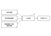
- FIG. 2 is a diagram illustrating a method for generating a prediction model.
- FIG. 3A is a diagram showing an example of surrounding environment information.
- FIG. 3B is a diagram showing an example of surrounding environment information.
- FIG. 4A is a diagram illustrating an example of generation of a prediction model.
- FIG. 4B is a diagram illustrating an example of generation of a prediction model.
- FIG. 5 is a diagram showing a method for predicting target information.
- FIG. 6 is a top view showing the indoor experimental environment and terminal movements.
- FIG. 7A is a diagram showing an example of a predicted throughput.
- FIG. 7B is a diagram showing an example of a predicted throughput.
- FIG. 7A is a diagram showing an example of a predicted throughput.
- FIG. 7C is a diagram showing an example of a predicted throughput.
- FIG. 7D is a diagram showing an example of a predicted throughput.
- FIG. 8 is a diagram showing the R2 scores of the predicted results for each throughput.
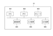
- FIG. 9 is a diagram showing the hardware configuration of a base station and a mobile radio communication terminal.
- the radio wave propagation environment between the communication party changes depending on the state of the wireless communication terminal (e.g., position, posture, movement) and the state of static or dynamic objects existing around the wireless communication terminal, which may degrade the communication quality of wireless communication and significantly affect the services realized by wireless communication.
- the higher the frequency used the more directional the radio waves tend to be, and the more susceptible the communication quality of wireless communication is to be affected.
- modeling the relationship between communication quality and environmental information using machine learning is considered to be a useful method. If a predictive model is constructed using machine learning, it is possible to use input signals obtained from the state of the wireless communication terminal and environmental information to output predicted values for wireless communication quality and control information for the wireless communication system.
- the present disclosure therefore predicts the communication quality of wireless communication using a machine learning model, using physical space information relating to various physical spaces, including terminal information and surrounding environment information, as input information.
- the present disclosure inputs terminal information, including at least one of the position, orientation, speed, operation, control status, and usage status of the terminal performing wireless communication, and surrounding environment information relating to the terminal's surrounding environment, into a prediction model, and makes a prediction. This makes it possible to predict the communication quality of wireless communication with a high degree of accuracy.
- terminal information including at least one of the terminal's position, orientation, speed, operation, control status, and usage status
- the number of machine learning parameters to be optimized is reduced, and the costs associated with learning and using the predictive model can be reduced.
- FIG. 1 is a diagram showing the configuration of a wireless communication system according to this embodiment.
- the wireless communication system 1 includes a base station 10 connected to a specific communication network, and a first mobile wireless communication terminal 20A and a second mobile wireless communication terminal 20B that perform wireless communication with the base station 10 and/or with each other.
- the number of mobile wireless communication terminals may be one or more.
- the base station 10 includes a first processing unit 11, a second processing unit 12, a third processing unit 13, a generating unit 14, a predicting unit 15, a first communication unit 16a, and a second communication unit 16b.
- the number of communication units may be one or more.
- the base station 10 may be a wireless LAN router or the like.
- the first processing unit 11 has a function of processing (generating, acquiring) terminal information (device information) related to the terminal to be predicted.
- the terminal to be predicted is, for example, the first mobile wireless communication terminal 20A, which is a partner terminal with which wireless communication is performed.
- the terminal information is, for example, the position, orientation, speed, and operation (e.g., rotation of the terminal, change of antenna angle), control status (e.g., the presence or absence of control commands for circuits, control command information, total amount of execution commands for application programs), and usage status (e.g., CPU usage, data communication volume) of the first mobile wireless communication terminal 20A, which is the other terminal with which wireless communication is performed.
- the first processing unit 11 processes the terminal information including at least one of these.
- the second processing unit 12 has the function of processing (generating and acquiring) surrounding environment information related to the surrounding environment of the base station 10 and the other terminal.
- the surrounding environment information is, for example, image information captured by the base station 10's built-in camera or a camera installed in the surrounding environment, sensor information sensed by a sensor installed in the surrounding environment, information extracted from the image information and sensor information, information about other terminals present in the vicinity of the base station 10 (for example, position information, orientation information, speed information, terminal information, and control information of the second mobile wireless communication terminal 20B that is not the other terminal with which wireless communication is performed), and information other than other terminals present in the vicinity of the base station 10 (for example, position information, orientation information, and speed information of passersby).
- the surrounding environment information is information about objects (for example, terminals, passersby, vehicles, and buildings) present in the vicinity of the base station 10 or the other terminal.
- the surrounding environment information may be information generated based on such information.
- the second processing unit 12 may generate the surrounding environment information based on object distribution data obtained from sensor information (object distribution data including the base station 10, its manager, the manager's belongings, the first mobile wireless communication terminal 20A, its owner/occupant, the owner's/occupant's belongings/occupied items, etc.).
- the third processing unit 13 has a function of processing (acquiring, generating) communication information related to wireless communication between the base station 10 and the other terminal. For example, the third processing unit 13 acquires communication information related to wireless communication between the base station 10 and the first mobile wireless communication terminal 20A.
- the communication information related to wireless communication is information related to wireless communication signals and wireless communication data obtained from the first communication unit 16a and the second communication unit 16b.
- the information includes received signal power, signal-to-noise power ratio, signal-to-interference plus noise power ratio, RSSI (Received Signal Strength Indication), RSRQ (Received Signal Reference Quality), packet error rate, number of arriving bits, bit error rate, number of arriving bits per unit time, MCS (Modular Code Index), number of retransmissions, packet arrival delay time, error correction technology settings, user contract information of the mobile wireless communication terminal, differential information of these values, indices calculated from these values using a predetermined formula, frequency conditions such as the frequency of the wireless communication system and the bandwidth of the resources used, and setting items of the wireless communication system that affect these indices.
- the generation unit 14 has a function of inputting the terminal information, the surrounding environment information, and the communication information related to wireless communication as learning data, and using an arbitrary machine learning algorithm to perform machine learning on the relationship between the terminal information, the surrounding environment information, and the communication information related to wireless communication, and generating a prediction model that predicts the communication information related to wireless communication as target information based on the terminal information and the surrounding environment information.
- the generation unit 14 can also perform learning by adding wireless communication system information.
- the generation unit 14 generates a prediction model that predicts communication information related to wireless communication as target information based on the terminal information, surrounding environment information, and wireless communication system information.
- the prediction unit 15 has a function of predicting communication information related to wireless communication as target information based on the input terminal information and surrounding environment information using a prediction model. When wireless communication system information is available, the prediction unit 15 predicts communication information related to wireless communication as target information based on the input terminal information, surrounding environment information, and wireless communication system information.
- Target information is, for example, communication information related to wireless communication, and parameters for controlling wireless communication.
- the contents of the target information can be selected arbitrarily.
- Parameters are, for example, information on the movement of the base station 10 and the other terminal, control information in the OSI reference model from the physical layer to the application layer (e.g., mode, communication speed, communication destination, communication path, communication method), and control information on structures, metamaterials, and dielectrics that affect the radio wave propagation environment (e.g., control information related to position, movement, and settings).
- the first communication unit 16a has the function of performing wireless communication with the first mobile wireless communication terminal 20A.
- the second communication unit 16b has a function of performing wireless communication with the second mobile wireless communication terminal 20B.
- the first mobile radio communication terminal 20A is, for example, a mobile phone terminal or a smartphone terminal, and includes a first processing unit 21A, a second processing unit 22A, a third processing unit 23A, a generating unit 24A, a predicting unit 25A, and a communication unit 26A.
- the first processing unit 21A like the first processing unit 11 of the base station 10, has a function of processing (obtaining, generating) terminal information related to the terminal to be predicted.
- the terminal to be predicted may be the base station 10, the second mobile wireless communication terminal 20B, or the first mobile wireless communication terminal 20A itself.
- the second processing unit 22A like the second processing unit 12 of the base station 10, has a function of processing (acquiring, generating) surrounding environment information related to the surrounding environment of the first mobile wireless communication terminal 20A.
- the second processing unit 22A may generate surrounding environment information based on object distribution data (object distribution data including the first mobile wireless communication terminal 20A, its owner/occupant, the possessions/occupancies of the owner/occupant, etc.) obtained from sensor information.
- object distribution data object distribution data including the first mobile wireless communication terminal 20A, its owner/occupant, the possessions/occupancies of the owner/occupant, etc.
- the third processing unit 23A like the third processing unit 13 of the base station 10, has the function of processing (acquiring, generating) communication information related to wireless communication between the first mobile wireless communication terminal 20A and the other terminal.
- the generation unit 24A has a function of inputting terminal information, surrounding environment information, and communication information related to wireless communication as learning data, and using any machine learning algorithm to perform machine learning on the relationship between the terminal information, surrounding environment information, and communication information related to wireless communication, and generating a prediction model that predicts communication information related to wireless communication as target information based on the terminal information and surrounding environment information.
- the generation unit 24A may also perform machine learning by adding wireless communication system information, and generate a prediction model that includes wireless communication system information in the input information.
- the prediction unit 25A like the prediction unit 15 of the base station 10, has a function of predicting communication information related to wireless communication as target information based on the input terminal information and surrounding environment information using a prediction model.
- the prediction unit 15 predicts communication information related to wireless communication as target information based on the input terminal information, surrounding environment information, and wireless communication system information.
- the communication unit 26A has the function of performing wireless communication with the first communication unit 16a of the base station 10, and performing wireless communication with the communication unit 26B of the second mobile wireless communication terminal 20B.
- the second mobile wireless communication terminal 20B is, for example, a mobile phone terminal or a smartphone terminal.
- the second mobile wireless communication terminal 20B includes a first processing unit 21B, a second processing unit 22B, a third processing unit 23B, a generating unit 24B, a predicting unit 25B, and a communication unit 26B.
- the second mobile wireless communication terminal 20B includes the same functions as the first mobile wireless communication terminal 20A. The description thereof will be omitted.
- the generation units 14, 24A, 24B that generate the predictive models may be provided in only one of the base station 10, the first mobile radio communication terminal 20A, and the second mobile radio communication terminal 20B, or may be provided in each terminal.
- the base station 10 which accommodates multiple mobile wireless communication terminals, to have it. This is because more wireless communication information can be collected and more training data can be used, which leads to improved accuracy of the prediction model. In this case, terminals other than the base station 10 use the prediction model generated by the base station 10.
- the prediction model may be optimized for each terminal using techniques such as transfer learning and fine tuning so that the prediction model is optimized for each terminal.
- wireless communication examples include wireless LAN (Local Area Network) defined by the standard IEEE 802.11, Bluetooth (registered trademark), cellular communication using LTE or 5G, LPWA (Low Power Wide Area) communication for IoT, ETC (Electronic Toll Collection System) used for vehicle communication, VICS (Vehicle Information and Communication System), and ARIB-STD-T109.
- wireless LAN Local Area Network
- Bluetooth registered trademark
- LPWA Low Power Wide Area
- LPWA Low Power Wide Area
- ETC Electronic Toll Collection System
- VICS Vehicle Information and Communication System
- ARIB-STD-T109 examples of wireless communication
- [Method of generating a predictive model] 2 is a diagram showing a method for generating a prediction model. A case in which a first mobile radio communication terminal 20A generates a prediction model will be described. It is assumed that the first mobile radio communication terminal 20A is performing radio communication with the base station 10.
- Step S101 The first processing section 21A acquires location information of the first mobile radio communication terminal 20A as terminal information.
- Step S102 The second processing unit 22A acquires point cloud data on the positions of objects in the surrounding environment from a LiDAR (Laser Imaging Detection and Ranging) installed in the surrounding environment of the first mobile wireless communication terminal 20A, converts the point cloud data into an image, and acquires the image as surrounding environment information. Examples of the image are shown in Figures 3A and 3B.
- the white parts represent the positions of the walls that form the experimental environment from an aerial perspective.
- Step S103 The third processing unit 23A acquires the throughput of the wireless communication carried out between the first mobile wireless communication terminal 20A and the base station 10 as communication information related to the wireless communication.
- Step S104 As shown in FIG. 4A , the generation unit 24A inputs terminal information (location information), surrounding environment information (image), and communication information related to wireless communication (throughput of wireless communication) as learning data, performs machine learning on the relationship between the terminal information and the surrounding environment information and the communication information related to wireless communication, and generates a prediction model that predicts the communication information related to wireless communication (throughput of wireless communication) as target information based on the terminal information and the surrounding environment information.
- terminal information location information
- surrounding environment information image
- communication information related to wireless communication throughput of wireless communication
- the generation unit 14 may perform learning by adding wireless communication system information and generate a prediction model that also uses the wireless communication system information as input information.
- [Method of predicting target information] 5 is a diagram showing a method for predicting target information. A case in which target information is predicted by a first mobile wireless communication terminal 20A will be described. It is assumed that the first mobile wireless communication terminal 20A is performing wireless communication with the base station 10.
- Step S201 The first processing unit 21A acquires the current location information of the first mobile radio communication terminal 20A as terminal information.
- Step S202 The second processing unit 22A acquires point cloud data regarding the current positions of objects in the surrounding environment from a LiDAR installed in the surrounding environment of the first mobile wireless communication terminal 20A, converts the point cloud data into an image, and acquires the image as surrounding environment information.
- Step S203 The prediction unit 15 uses the prediction model generated in step S104 to predict and output communication information related to wireless communication (throughput of wireless communication) as target information based on the terminal information (current location information) acquired in step S201 and the surrounding environment information (image related to point cloud data related to the current location) acquired in step S202.
- the prediction model is formed so as to output communication information related to wireless communication or some parameter as target information based on input information.
- the prediction model may be constructed so that the output value as target information is a highly accurate predicted value of some parameter, or it may output a strategy (improvement proposal) for changing the position of each communication unit to improve parameters related to wireless communication, or for the terminal components, surrounding environment, or from the application layer to the physical layer in the OSI reference model.
- the prediction model may be constructed by reinforcement learning so as to maximize the parameters related to wireless communication. For example, when predicting the received power at a future time, the received power at a future time is used as a parameter of the target information, and a prediction model is constructed so that the error between the predicted value of the output received power and the actual received power is reduced.
- a reward is set for maximizing the received power using reinforcement learning, and a prediction model is formed to output the X-coordinate velocity, Y-coordinate position velocity, and rotation command that will increase the reward.
- machine learning blocks constructed with the same coefficients and structure may be shared.
- a predictive model generated on one terminal and a predictive model generated on another terminal will have the same or similar structures if those terminals are in the same environment, so a predictive model can be generated using the same machine learning blocks, the other terminal's predictive model can be used as is, or part of the other terminal's predictive model can be modified to generate a predictive model. This allows predictive models to be constructed efficiently and reduces costs associated with the predictive models.
- Figure 6 is a top view showing the indoor experimental environment and the movement of the terminal. Two autonomous mobile robots equipped with a phantom simulating a human body and measuring devices for position information, etc. were driven.
- One of the robots was designated the target robot 300, and it was made to move around the experimental environment with a first mobile wireless communication terminal 20A capable of 5G communication strapped to its back, and UDP communication was carried out between the robot and base station 10, a 5G base station. The throughput of wireless communication between the first mobile wireless communication terminal 20A and base station 10 was measured.
- the other robot was a blocking robot 500, which was made to travel within the experimental environment as a robot that interferes with wireless communication between the first mobile wireless communication terminal 20A and the base station 10.
- the blocking robot 500 blocks the wireless communication path between the target robot 300 and the base station 10, thus affecting the wireless communication between them.
- the first mobile wireless communication terminal 20A acquires the position, orientation, forward speed, and rotation speed of the target robot 300 from the target robot 300 as terminal information.
- the first mobile wireless communication terminal 20A also acquires the position, orientation, forward speed, and rotation speed of the blocking robot 500 from the blocking robot 500 as surrounding environment information.
- the first mobile wireless communication terminal 20A uses the acquired terminal information and surrounding environment information as input information and predicts the throughput of wireless communication as target information.
- Figures 7A to 7D show the results of evaluation using four types of input information for the prediction.
- the horizontal axis is time, and the vertical axis is throughput.
- the solid lines in Figures 7A to 7D show the correct throughput to be predicted, as actually observed.
- the dashed line in Figure 7A shows the throughput prediction results when past throughput (two values in total: the current throughput value and the throughput value from 5 seconds ago) is used as input information.
- the dashed line in Figure 7B shows the throughput prediction result when the position information of the target robot 300 (two values in total: X coordinate value and Y coordinate value on a two-dimensional plane) is used as input information.
- the dashed line in Figure 7C shows the throughput prediction result when the position information, orientation information, and speed information of the target robot 300 (6 values in total: X coordinate value, Y coordinate value, sin( ⁇ /2) and cos( ⁇ /2) of the angle ⁇ from the X coordinate axis, speed in the direction of travel, and rotational speed) are used as input information.
- the dashed line in Figure 7D shows the throughput prediction result when the position information, orientation information, and speed information of the target robot 300 and the position information, orientation information, and speed information of the blocking robot 500 (a total of 12 values) are used as input information.
- the dashed line in Figure 7D shows the prediction result of this embodiment.
- each throughput prediction result was evaluated using the R2 score evaluation function shown in formula (1).
- C[t] is the throughput indicated by the solid line
- C ave [t] is the average throughput indicated by the solid line
- C'[t] is the throughput prediction result indicated by the dashed line.
- the R2 score for each throughput prediction result is shown in Figure 8.
- the R2 score when using past throughput is 0.61, and when predicted simply from the position information of the target robot (T robot) 300, it is 0.43, which is lower than the prediction when past throughput information is used.
- the orientation information and speed information of the target robot 300 are also used, it is 0.60, which is a prediction with a high level of accuracy equivalent to that when past throughput information is used.
- the prediction accuracy is 0.68, which confirms that a higher prediction accuracy is obtained. From this result, it can be said that by making predictions using both terminal information and surrounding environment information, the communication quality of wireless communication can be predicted with high accuracy.
- communication information related to wireless communication is predicted using a prediction model that predicts communication information related to wireless communication based on terminal information of the terminal and surrounding environment information related to the terminal's surrounding environment, so that the communication quality of wireless communication can be predicted with high accuracy.
- terminal information including at least one of the terminal's position, orientation, speed, operation, control status, and usage status is used, which reduces the number of machine learning parameters to be optimized and reduces the costs associated with learning and using the predictive model.
- the base station 10 of the present embodiment described above can be realized, for example, as shown in FIG. 9, by using a general-purpose computer system equipped with a CPU 901, memory 902, storage 903, communication device 904, input device 905, and output device 906.
- the memory 902 and storage 903 are storage devices.
- the CPU 901 executes a predetermined program loaded onto the memory 902, thereby realizing each function of the base station 10.
- the base station 10 may be implemented by one computer.
- the base station 10 may be implemented by multiple computers.
- the base station 10 may be a virtual machine implemented on a computer.
- the base station 10 may be realized using hardware such as a PLD (Programmable Logic Device) or an FPGA (Field Programmable Gate Array).
- the program for the base station 10 can be stored in a computer-readable recording medium such as a HDD, SSD, USB memory, CD, or DVD.
- the computer-readable recording medium is, for example, a non-transitory recording medium.
- the program for the base station 10 can also be distributed via a communication network such as the Internet or a telephone line.
- the first mobile wireless communication terminal 20A and the second mobile wireless communication terminal 20B also have the same hardware configuration as the base station 10.
- Base station 20A First mobile wireless communication terminal (mobile wireless communication device) 20B Second mobile wireless communication terminal (mobile wireless communication device) 11, 21A, 21B First processing unit 12, 22A, 22B Second processing unit 13, 23A, 23B Third processing unit 14, 24A, 24B Generation unit 15, 25A, 25B Prediction unit 16a First communication unit 16b Second communication unit 26A, 26B Communication unit 300 Target robot 500 Blocking robot 901 CPU 902 Memory 903 Storage 904 Communication device 905 Input device 906 Output device
Landscapes
- Engineering & Computer Science (AREA)
- Computer Networks & Wireless Communication (AREA)
- Signal Processing (AREA)
- Mobile Radio Communication Systems (AREA)
Priority Applications (2)
| Application Number | Priority Date | Filing Date | Title |
|---|---|---|---|
| PCT/JP2023/017400 WO2024232005A1 (ja) | 2023-05-09 | 2023-05-09 | 無線通信システム |
| JP2025519220A JPWO2024232005A1 (https=) | 2023-05-09 | 2023-05-09 |
Applications Claiming Priority (1)
| Application Number | Priority Date | Filing Date | Title |
|---|---|---|---|
| PCT/JP2023/017400 WO2024232005A1 (ja) | 2023-05-09 | 2023-05-09 | 無線通信システム |
Publications (1)
| Publication Number | Publication Date |
|---|---|
| WO2024232005A1 true WO2024232005A1 (ja) | 2024-11-14 |
Family
ID=93431477
Family Applications (1)
| Application Number | Title | Priority Date | Filing Date |
|---|---|---|---|
| PCT/JP2023/017400 Ceased WO2024232005A1 (ja) | 2023-05-09 | 2023-05-09 | 無線通信システム |
Country Status (2)
| Country | Link |
|---|---|
| JP (1) | JPWO2024232005A1 (https=) |
| WO (1) | WO2024232005A1 (https=) |
Cited By (1)
| Publication number | Priority date | Publication date | Assignee | Title |
|---|---|---|---|---|
| US20240036227A1 (en) * | 2020-12-17 | 2024-02-01 | Nippon Telegraph And Telephone Corporation | Object detection system and object detection method |
Citations (2)
| Publication number | Priority date | Publication date | Assignee | Title |
|---|---|---|---|---|
| WO2020217457A1 (ja) * | 2019-04-26 | 2020-10-29 | 日本電信電話株式会社 | 通信システム及び基地局 |
| WO2021064849A1 (ja) * | 2019-10-01 | 2021-04-08 | 日本電信電話株式会社 | 通信端末及び通信品質予測方法 |
-
2023
- 2023-05-09 JP JP2025519220A patent/JPWO2024232005A1/ja active Pending
- 2023-05-09 WO PCT/JP2023/017400 patent/WO2024232005A1/ja not_active Ceased
Patent Citations (2)
| Publication number | Priority date | Publication date | Assignee | Title |
|---|---|---|---|---|
| WO2020217457A1 (ja) * | 2019-04-26 | 2020-10-29 | 日本電信電話株式会社 | 通信システム及び基地局 |
| WO2021064849A1 (ja) * | 2019-10-01 | 2021-04-08 | 日本電信電話株式会社 | 通信端末及び通信品質予測方法 |
Cited By (1)
| Publication number | Priority date | Publication date | Assignee | Title |
|---|---|---|---|---|
| US20240036227A1 (en) * | 2020-12-17 | 2024-02-01 | Nippon Telegraph And Telephone Corporation | Object detection system and object detection method |
Also Published As
| Publication number | Publication date |
|---|---|
| JPWO2024232005A1 (https=) | 2024-11-14 |
Similar Documents
| Publication | Publication Date | Title |
|---|---|---|
| US8744485B2 (en) | Efficient location discovery | |
| Parvaresh et al. | A continuous actor–critic deep Q-learning-enabled deployment of UAV base stations: Toward 6G small cells in the skies of smart cities | |
| JP2022153344A (ja) | 再構成可能なインテリジェントサーフェスを用いた無人航空機の動的制御 | |
| Zhou et al. | Hierarchical digital-twin-enhanced cooperative sensing for UAV swarms | |
| CN117256171A (zh) | 经由对象特定的射频参数的对象数据图的增强 | |
| WO2024232005A1 (ja) | 無線通信システム | |
| Lai et al. | Flight direction-based handover in cellular-connected UAV communications | |
| Yang et al. | Research on path planning in UAV-assisted emergency communication | |
| CN119233320B (zh) | 面向森林救火的无人机协助通感算一体化资源分配方法 | |
| JP7439948B2 (ja) | 通信情報予測装置、通信情報予測方法、および通信情報予測プログラム | |
| JP7276481B2 (ja) | 移動端末及び通信品質予測方法 | |
| CA3209812A1 (en) | Decentralized control of beam generating devices | |
| Wang et al. | KOGPSR: A 3D GPSR algorithm using adaptive Kalman prediction for FANETs with omnidirectional antenna | |
| JP7545076B2 (ja) | 情報処理装置、情報処理方法、およびプログラム | |
| JP7505569B2 (ja) | 通信情報予測装置、通信情報予測方法、および通信情報予測プログラム | |
| WO2025097782A1 (zh) | 定位方法、网络设备、终端设备和通信系统 | |
| Ali et al. | 5G Unmanned Aerial Vehicle Placement for Mountainous Environment using Deep Reinforcement Learning | |
| Imianvan et al. | Optimizing 5G IoT Connectivity for Path Loss Reduction through Ant Colony Optimization and Support Vector Regression | |
| WO2024150327A1 (ja) | 予測装置、学習装置、予測システム、予測方法、及びプログラム | |
| Ghaffarkhah et al. | Communication-aware navigation functions for cooperative target tracking | |
| CN116980929A (zh) | 无线网络优化方法、装置、设备以及计算机存储介质 | |
| Zhang et al. | Mobile robot path planning method based on sumtree-TD3 algorithm with transfer learning | |
| CN121002793A (zh) | 一种电磁环境模型训练的方法及相应装置 | |
| CN114697974A (zh) | 网络覆盖优化方法、装置、电子设备及存储介质 | |
| JP2022135621A (ja) | 情報処理装置および情報処理方法 |
Legal Events
| Date | Code | Title | Description |
|---|---|---|---|
| 121 | Ep: the epo has been informed by wipo that ep was designated in this application |
Ref document number: 23936559 Country of ref document: EP Kind code of ref document: A1 |
|
| ENP | Entry into the national phase |
Ref document number: 2025519220 Country of ref document: JP Kind code of ref document: A |
|
| WWE | Wipo information: entry into national phase |
Ref document number: 2025519220 Country of ref document: JP |
|
| NENP | Non-entry into the national phase |
Ref country code: DE |