WO2024228329A1 - 情報処理装置、方法、およびプログラム - Google Patents
情報処理装置、方法、およびプログラム Download PDFInfo
- Publication number
- WO2024228329A1 WO2024228329A1 PCT/JP2024/014972 JP2024014972W WO2024228329A1 WO 2024228329 A1 WO2024228329 A1 WO 2024228329A1 JP 2024014972 W JP2024014972 W JP 2024014972W WO 2024228329 A1 WO2024228329 A1 WO 2024228329A1
- Authority
- WO
- WIPO (PCT)
- Prior art keywords
- user
- unit
- intervention
- person
- information
- Prior art date
- Legal status (The legal status is an assumption and is not a legal conclusion. Google has not performed a legal analysis and makes no representation as to the accuracy of the status listed.)
- Ceased
Links
Images









Classifications
-
- G—PHYSICS
- G06—COMPUTING OR CALCULATING; COUNTING
- G06F—ELECTRIC DIGITAL DATA PROCESSING
- G06F3/00—Input arrangements for transferring data to be processed into a form capable of being handled by the computer; Output arrangements for transferring data from processing unit to output unit, e.g. interface arrangements
- G06F3/01—Input arrangements or combined input and output arrangements for interaction between user and computer
-
- G—PHYSICS
- G06—COMPUTING OR CALCULATING; COUNTING
- G06F—ELECTRIC DIGITAL DATA PROCESSING
- G06F3/00—Input arrangements for transferring data to be processed into a form capable of being handled by the computer; Output arrangements for transferring data from processing unit to output unit, e.g. interface arrangements
- G06F3/01—Input arrangements or combined input and output arrangements for interaction between user and computer
- G06F3/011—Arrangements for interaction with the human body, e.g. for user immersion in virtual reality
-
- G—PHYSICS
- G06—COMPUTING OR CALCULATING; COUNTING
- G06F—ELECTRIC DIGITAL DATA PROCESSING
- G06F3/00—Input arrangements for transferring data to be processed into a form capable of being handled by the computer; Output arrangements for transferring data from processing unit to output unit, e.g. interface arrangements
- G06F3/01—Input arrangements or combined input and output arrangements for interaction between user and computer
- G06F3/048—Interaction techniques based on graphical user interfaces [GUI]
- G06F3/0481—Interaction techniques based on graphical user interfaces [GUI] based on specific properties of the displayed interaction object or a metaphor-based environment, e.g. interaction with desktop elements like windows or icons, or assisted by a cursor's changing behaviour or appearance
-
- H—ELECTRICITY
- H04—ELECTRIC COMMUNICATION TECHNIQUE
- H04N—PICTORIAL COMMUNICATION, e.g. TELEVISION
- H04N21/00—Selective content distribution, e.g. interactive television or video on demand [VOD]
- H04N21/40—Client devices specifically adapted for the reception of or interaction with content, e.g. set-top-box [STB]; Operations thereof
- H04N21/41—Structure of client; Structure of client peripherals
- H04N21/4104—Peripherals receiving signals from specially adapted client devices
- H04N21/4126—The peripheral being portable, e.g. PDAs or mobile phones
-
- H—ELECTRICITY
- H04—ELECTRIC COMMUNICATION TECHNIQUE
- H04N—PICTORIAL COMMUNICATION, e.g. TELEVISION
- H04N21/00—Selective content distribution, e.g. interactive television or video on demand [VOD]
- H04N21/40—Client devices specifically adapted for the reception of or interaction with content, e.g. set-top-box [STB]; Operations thereof
- H04N21/41—Structure of client; Structure of client peripherals
- H04N21/422—Input-only peripherals, i.e. input devices connected to specially adapted client devices, e.g. global positioning system [GPS]
- H04N21/42202—Input-only peripherals, i.e. input devices connected to specially adapted client devices, e.g. global positioning system [GPS] environmental sensors, e.g. for detecting temperature, luminosity, pressure, earthquakes
-
- H—ELECTRICITY
- H04—ELECTRIC COMMUNICATION TECHNIQUE
- H04N—PICTORIAL COMMUNICATION, e.g. TELEVISION
- H04N21/00—Selective content distribution, e.g. interactive television or video on demand [VOD]
- H04N21/40—Client devices specifically adapted for the reception of or interaction with content, e.g. set-top-box [STB]; Operations thereof
- H04N21/43—Processing of content or additional data, e.g. demultiplexing additional data from a digital video stream; Elementary client operations, e.g. monitoring of home network or synchronising decoder's clock; Client middleware
- H04N21/431—Generation of visual interfaces for content selection or interaction; Content or additional data rendering
-
- H—ELECTRICITY
- H04—ELECTRIC COMMUNICATION TECHNIQUE
- H04N—PICTORIAL COMMUNICATION, e.g. TELEVISION
- H04N21/00—Selective content distribution, e.g. interactive television or video on demand [VOD]
- H04N21/40—Client devices specifically adapted for the reception of or interaction with content, e.g. set-top-box [STB]; Operations thereof
- H04N21/43—Processing of content or additional data, e.g. demultiplexing additional data from a digital video stream; Elementary client operations, e.g. monitoring of home network or synchronising decoder's clock; Client middleware
- H04N21/442—Monitoring of processes or resources, e.g. detecting the failure of a recording device, monitoring the downstream bandwidth, the number of times a movie has been viewed, the storage space available from the internal hard disk
-
- H—ELECTRICITY
- H04—ELECTRIC COMMUNICATION TECHNIQUE
- H04N—PICTORIAL COMMUNICATION, e.g. TELEVISION
- H04N21/00—Selective content distribution, e.g. interactive television or video on demand [VOD]
- H04N21/40—Client devices specifically adapted for the reception of or interaction with content, e.g. set-top-box [STB]; Operations thereof
- H04N21/47—End-user applications
- H04N21/488—Data services, e.g. news ticker
- H04N21/4882—Data services, e.g. news ticker for displaying messages, e.g. warnings, reminders
Definitions
- This technology relates to an information processing device, method, and program, and in particular to an information processing device, method, and program that can support users in taking rapid action and reduce risks.
- HMDs head mounted displays
- VR virtual reality
- users generally wear an HMD, but because wearing an HMD blocks the view and sound of the surroundings, they often do not notice obstacles or people's intervention (such as calls) in the vicinity.
- Patent Document 1 proposes a technology that detects real obstacles around the user, replaces the obstacles with virtual objects, and displays them on the HMD screen.
- Patent Document 1 does not mention the detection of human intervention.
- This technology was developed in light of these circumstances, and is designed to help users respond quickly and reduce risks.
- An information processing device includes a detection unit that detects an external intervener who is wearing a user device that blocks outside vision and sound, and a presentation control unit that controls the presentation of information about the detected intervener to the user.
- an external intervener is detected when a user is wearing a user device that blocks outside vision and sound, and control is performed to present information about the detected intervener to the user.
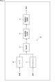
- FIG. 1 is a block diagram showing an example of the configuration of an ambient computing system according to an embodiment of the present technology
- 1 is a diagram showing an overview of an HMD system according to a first embodiment of the present technology.
- FIG. 3 is a block diagram showing an example of the configuration of the HMD system shown in FIG. 2.
- FIG. 4 is a block diagram showing an example of the configuration of a detection unit in FIG. 3 .
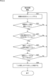
- 3 is a flowchart illustrating a process of the HMD system of FIG. 2 .
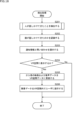
- 6 is a flowchart illustrating the detection process in step S11 of FIG. 5 .
- FIG. 3 is a diagram showing a modified example of the HMD system of FIG. 2.
- 10 is a flowchart illustrating another process of the HMD system of FIG. 2 .
- FIG. 9 is a flowchart illustrating the detection process in step S51 of FIG. 8.
- 10 is a flowchart illustrating another example of the detection process in step S51 of FIG. 8 .
- FIG. 11 is a diagram illustrating an overview of an HMD system according to a second embodiment of the present technology.
- FIG. 12 is a block diagram showing an example of the configuration of the HMD system shown in FIG. 11 .
- 12 is a flowchart illustrating the process of the HMD system of FIG. 11 .
- FIG. 13 is a block diagram showing a configuration example of an HMD system according to a third embodiment of the present technology.
- FIG. 13 is a diagram illustrating an overview of an HMD system according to a fourth embodiment of the present technology.
- FIG. 11 is a diagram illustrating an overview of an HMD system according to a second embodiment of the present technology.
- FIG. 16 is a block diagram showing an example of the configuration of the HMD system shown in FIG. 15 .
- FIG. 13 is a block diagram showing a configuration example of an HMD system according to a fifth embodiment of the present technology.
- 18 is a flowchart illustrating the processing of the HMD system of FIG. 17.
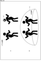
- FIG. 13 is a diagram illustrating communication between a user and an intervener. 13 is a diagram showing a display method for presenting an image of an intervention participant to a user.
- FIG. 18 is a flowchart illustrating another process of the HMD system of FIG. 17.
- FIG. 13 is a block diagram showing a configuration example of an HMD system according to a sixth embodiment of the present technology.
- 23 is a flowchart illustrating the processing of the HMD system of FIG. 22.
- FIG. 22 is a flowchart illustrating the processing of the HMD system of FIG. 22.
- FIG. 13 is a diagram showing a method of presenting a message to a person who has spoken to the user.
- FIG. 13 is a diagram showing an overview of an HMD system according to a seventh embodiment of the present technology.
- FIG. 23 is a diagram showing an overview of an HMD system according to an eighth embodiment of the present technology.
- 27 is a flowchart illustrating the processing of the HMD system of FIG. 26.
- FIG. 28 is a flowchart illustrating a first control process according to an intervention level by an HMD system according to a ninth embodiment of the present technology.
- FIG. 13 is a diagram showing a control method depending on whether the user and the intervener are an adult or a child.
- FIG. 23 is a flowchart illustrating a second control process according to an intervention level by an HMD system according to a ninth embodiment of the present technology.
- FIG. 13 is a diagram illustrating an example of a control method determination table. A figure showing an example of a VR space that a user can view or experience.
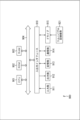
- FIG. 2 is a block diagram showing an example of the configuration of a computer.
- FIG. 1 is a diagram showing an example of the configuration of an ambient computing system according to an embodiment of the present technology.
- the ambient computing system 1 in Figure 1 is a system that detects the situation and surrounding environment of the user, controls each device according to the detected information and prior information, and provides the services desired by the user.
- the ambient computing system 1 provides, as a function related to the present technology, a service that detects human intervention while a user is viewing VR content (hereinafter referred to as “viewing VR”), controls the HMD in response to the detected human intervention, and presents information.
- viewing VR a service that detects human intervention while a user is viewing VR content
- the ambient computing system 1 is configured to include a user interface 21, an environmental advance information acquisition unit 22, a user advance information acquisition unit 23, a collaborative sensing unit 24, a surrounding environment detection unit 25, a user state detection unit 26, a user response detection unit 27, a context management unit 28, a device control unit 29, an environmental context model storage unit 30, a user context model storage unit 31, and a service list storage unit 32.
- context refers to information that includes user information, environmental information, and the relationships between these pieces of information.
- the user interface 21 performs interface functions for the user, such as sending notifications to the user and accepting instructions from the user.
- the ambient computing system 1 has two paths for acquiring information.
- the first path is a path for acquiring advance information in advance based on user input.
- the first path is realized by the environmental advance information acquisition unit 22 and the user advance information acquisition unit 23.
- the environmental prior information acquisition unit 22 acquires prior information about the environment based on user input, and outputs the acquired environmental prior information to the context management unit 28 as environmental information.
- the environmental advance information acquisition unit 22 outputs, for example, information from a recognition database for recognizing the face and voice of a person intervening (hereinafter also referred to as the intervener) to the context management unit 28 as environmental information.
- a recognition database for recognizing the face and voice of a person intervening hereinafter also referred to as the intervener
- the user prior information acquisition unit 23 acquires prior information about the user based on user input, and outputs the acquired user prior information to the context management unit 28 as user information.
- the user prior information acquisition unit 23 outputs, for example, information indicating the type of viewing content being viewed by the user to the context management unit 28 as user information.
- the second path is a path that detects the environment and the user's current state information (in this technology, the state that the user is watching VR) through a recognizer that performs sensing by coordinating multiple sensing devices such as IoT (Internet of Things) and handles the sensing information, and is also capable of multimodal processing.
- Multimodal processing refers to processing multiple types of information at once.
- the second path is realized by a cooperative sensing unit 24 as a recognizer, a surrounding environment detection unit 25, a user state detection unit 26, and a user response detection unit 27.
- the collaborative sensing unit 24 acquires sensing information from multiple sensing devices and performs predetermined signal processing on the acquired information to make it easier to handle in subsequent processing, such as removing noise components and performing data cleansing to synchronize data.
- the collaborative sensing unit 24 outputs the processed information to the detection unit that corresponds to the information, among the surrounding environment detection unit 25, the user state detection unit 26, and the user response detection unit 27.
- the surrounding environment detection unit 25 detects surrounding information such as images, temperature, and sound from the information supplied by the collaborative sensing unit 24, and outputs information related to the environment obtained as a result of the detection (hereinafter referred to as environmental information) to the context management unit 28.
- the surrounding environment detection unit 25 detects human intervention, such as when a person is looking, approaching, or speaking to the device, and outputs the resulting environmental information to the context management unit 28.
- the user state detection unit 26 detects information about the user from the information supplied by the collaborative sensing unit 24. For example, the user state detection unit 26 performs personal identification of the user by face recognition using RGB images, detects the user's behavior from skeletal detection and environmental map information, and detects the user's emotions such as comfort or discomfort by multimodally processing facial expressions acquired from an RGB camera and vital information such as body temperature acquired from a wearable device.
- the user state detection unit 26 outputs information about the user obtained as a result of the detection (hereinafter referred to as user information) to the context management unit 28.
- the user state detection unit 26 detects, for example, that the user is watching VR, and outputs the user information obtained as a result to the context management unit 28.
- the user response detection unit 27 detects the user's response to the service provided by the context management unit 28 from the information supplied by the collaborative sensing unit 24, and outputs the user's response information and feedback information obtained as a result of the detection to the context management unit 28.
- the user response detection unit 27 detects, for example, the user's permission or selection for services such as notifications provided by the context management unit 28, and outputs the user's response information and feedback information obtained as a result to the context management unit 28.
- the context management unit 28 accumulates information supplied from the surrounding environment detection unit 25, the user state detection unit 26, and the user response detection unit 27, and learns an environmental model as an environmental context model, such as the type of environment that is likely to occur in this area during this time period.
- the context management unit 28 stores the learned environmental context model in the environmental context model storage unit 30.
- the context management unit 28 accumulates information supplied from the surrounding environment detection unit 25, the user state detection unit 26, and the user response detection unit 27, and learns a model of the user's habitual behavior, such as what activity the user is performing in what situation, as a user context model.
- the context management unit 28 stores the learned user context model in the user context model storage unit 31.
- the context management unit 28 learns each context model, and when information indicating a similar situation is obtained, it controls the device control unit 29 to provide personalized services that use the user context model to anticipate actions for the user from the devices linked to the ambient computing system 1.
- the context management unit 28 receives user responses when a personalized service is provided via the user response detection unit 27, obtains feedback information on whether the service was actually appropriate, and re-learns each context model to improve the accuracy of each context model.
- the context management unit 28 can also model behavioral norms that indicate which options a user is likely to choose in certain situations, making it possible to provide a personalized service to the user in advance, even if the user does not habitually do something.
- the context management unit 28 controls the device control unit 29 to provide personalized services such as notifications, presentations, and inquiries to the user from the HMD, which is one of the devices linked to the ambient computing system 1.
- the device control unit 29 causes the device (in this technology, the HMD) linked to the ambient computing system 1 to provide personalized services.
- the environmental context model storage unit 30 stores the environmental context model. In addition, the environmental context model storage unit 30 stores information used when learning the environmental context model and information including its relationships as environmental context.
- the user context model storage unit 31 stores the user context model.
- the user context model storage unit 31 stores information used when learning the user context model and information including the relationships between the information as user context.
- the service list storage unit 32 stores a list of devices that perform services that can be provided to users.
- FIG. 2 is a diagram illustrating an overview of an HMD system according to a first embodiment of the present technology.
- FIG. 2 the state of a user using an HMD system 51 having the functions of this technology in the ambient computing system 1 in FIG. 1 is shown.
- the HMD system 51 detects when a child is speaking to the user using a camera 62 and a microphone 71 (see FIG. 3, described below) provided in the HMD 61, and notifies the user of the detection result by displaying it on the HMD 61.
- FIG. 3 is a block diagram showing an example of the configuration of the HMD system 51 in FIG.
- the HMD system 51 is configured to include the camera 62, microphone 71, detection unit 72, notification information generation unit 73, and information presentation control unit 74 shown in FIG. 2.
- the camera 62, microphone 71, and detection unit 72 correspond to the collaborative sensing unit 24, surrounding environment detection unit 25, user state detection unit 26, and user response detection unit 27 in FIG. 1.
- the notification information generation unit 73 corresponds to the context management unit 28 in FIG. 1.
- the information presentation control unit 74 corresponds to the device control unit 29 in FIG. 1.
- Camera 62 is an imaging unit that captures the surroundings, and is provided in HMD 61 worn by the user. Camera 62 outputs video data generated by capturing the surroundings of the user to detection unit 72.
- the microphone 71 is a sound collection unit and is provided in the HMD 61 worn by the user.
- the microphone 71 collects sounds around the user and outputs the generated voice data to the detection unit 72.
- the detection unit 72 detects external human intervention (the presence of an intervening person) based on the video data supplied from the camera 62 and the audio data supplied from the microphone 71, and supplies the detection result to the notification information generation unit 73.
- Human intervention can be, for example, intervention by voice, such as someone speaking to you, intervention by gaze, such as someone looking at you, or intervention by action, such as someone approaching.
- the notification information generation unit 73 generates notification information that notifies the detection result supplied from the detection unit 72, and outputs the generated notification information to the information presentation control unit 74.
- the information presentation control unit 74 causes the notification information provided by the notification information generation unit 73 to be presented on a presentation unit (not shown) provided in the HMD 61.
- the notification information generated by the notification information generating unit 73 will be video data if the notification is by video, and will be audio data if the notification is by audio.
- FIG. 4 is a block diagram showing an example of the configuration of the detection unit 72 in FIG.
- the detection unit 72 is configured to include a person detection unit 81, a movement determination unit 82, a speech interval detection unit 83, a speaker recognition unit 84, a speaker data DB (Database) 85, and an intervention detection unit 86.
- the person detection unit 81 detects people from the video data supplied from the camera 62.
- the person detection unit 81 outputs information about the detected people to the movement determination unit 82.
- the motion determination unit 82 determines the face direction from the person information supplied by the person detection unit 81, and outputs the determination result of the face direction to the intervention detection unit 86.
- the motion determination unit 82 also determines whether the size of the person in the video is increasing from the person information supplied by the person detection unit 81, and outputs the determination result of whether the size of the person is increasing to the intervention detection unit 86.
- the speech interval detection unit 83 detects a speech interval from the voice data supplied from the microphone 71.
- the speech interval detection unit 83 outputs information indicating the detected speech interval to the speaker recognition unit 84.
- the speaker recognition unit 84 determines whether the person speaking (hereinafter also referred to as the speaker) is a person other than the user, based on the voice data of the speech section indicated by the information supplied from the speech section detection unit 83 and the speaker data registered in the speaker data DB 85.
- the speaker recognition unit 84 outputs the determined speaker information to the intervention detection unit 86.
- the intervention detection unit 86 detects human intervention, such as when a person speaks to the user, is looking at the user, or is approaching the user, based on the face direction determination result supplied from the movement determination unit 82 and speaker information supplied from the speaker recognition unit 84.
- the intervention detection unit 86 outputs the detection result of human intervention to the notification information generation unit 73.
- Fig. 5 is a flowchart for explaining the processing of the HMD system 51 in Fig. 2. The processing in Fig. 5 is performed for each frame or for each frame at a predetermined interval. Other processing of the HMD system described below is also performed for each frame or for each frame at a predetermined interval.
- a child might say to a user wearing the HMD 61 while watching VR, "Hey, hey, Dad.”
- step S11 the camera 62, microphone 71, and detection unit 72 detect that a person is speaking to them.
- the camera 62 and microphone 71 provided in the HMD 61 sense the situation around the user and output video data and audio data to the detection unit 72, respectively.
- the detection unit 72 detects that a person is speaking to the user based on the video data supplied from the camera 62 and the audio data supplied from the microphone 71, and supplies the detection result to the notification information generation unit 73. Details of the detection process in step S11 will be described later with reference to FIG. 6.
- step S12 the notification information generation unit 73 generates notification information notifying the user that a person has spoken to them, which is the detection result provided by the detection unit 72, and outputs the generated notification information to the information presentation control unit 74.
- step S13 the information presentation control unit 74 notifies the user that a person is speaking to them by displaying the notification information provided by the notification information generation unit 73 on a presentation unit provided in the HMD 61. Then, the process ends.
- FIG. 6 is a flowchart illustrating the details of the detection process in step S11 of FIG.
- step S31 the camera 52 and microphone 71 sense the surrounding situation.
- the camera 62 captures the user's surroundings and outputs the generated video data to the detection unit 72.
- the microphone 71 collects sounds around the user and outputs the generated audio data to the detection unit 72.
- step S32 the person detection unit 81 determines whether or not a person has been detected in the image of the video data supplied from the camera 62. If it is determined in step S32 that a person has not been detected in the image, the process returns to step S31, and the subsequent processes are repeated.
- step S32 If it is determined in step S32 that a person has been detected in the video, processing proceeds to step S33.
- step S33 the motion determination unit 82 determines whether the face of the person in the video is facing the direction of the user, based on the person information provided by the person detection unit 81. If it is determined in step S33 that the face of the person in the video is not facing the direction of the user, the process returns to step S31, and the subsequent processes are repeated.
- step S33 If it is determined in step S33 that the face of the person in the video is facing the user, processing proceeds to step S34.
- the vocalization section detection unit 83 detects the vocalization section from the collected sound based on the audio data supplied from the microphone 71.
- step S34 the vocalization section detection unit 83 determines whether or not a human voice has been detected from the collected sound, based on the audio data supplied from the microphone 71. If it is determined in step S34 that a human voice has not been detected from the collected sound, the process returns to step S31, and the subsequent processes are repeated.
- step S34 If it is determined in step S34 that a human voice has been detected from the collected sound, processing proceeds to step S35.
- step S35 the speaker recognition unit 84 determines whether the speaker is a person other than the user based on the voice data of the speech section indicated by the information supplied from the speech section detection unit 83 and the speaker data registered in the speaker data DB 85. If it is determined that the speaker is the user, the process returns to step S31, and the subsequent processes are repeated.
- step S35 If it is determined in step S35 that the speaker is someone other than the user, processing proceeds to step S36.
- step S36 the intervention detection unit 86 determines that "a person has spoken to the user" and outputs a detection result indicating that a person has spoken to the user. After that, the process returns to step S11 in FIG. 5.
- sensing is performed using the camera 62 and microphone 71 provided on the HMD 61, but if VR viewing is performed in a specific location, sensing may be performed using an external camera and microphone.
- FIG. 7 is a diagram showing a modified example of the HMD system of FIG.
- FIG. 7 an example is shown in which a user using the HMD system 51 is talking to a child while watching VR in a specific location such as a room.
- the HMD system 51 in FIG. 7 differs from the HMD system 51 in FIG. 2 in that the camera 62 and microphone 71 are replaced with a camera 91 and microphone 92.
- the camera 91 and microphone 92 are not installed in the HMD 61 but are installed outside the room, for example.
- camera 91 is configured the same as camera 62 except for its installation location.
- Microphone 92 is configured the same as microphone 71 except for its installation location.
- sensing may be performed using an external camera 91 and microphone 92.
- FIG. 8 is a flowchart illustrating another process of the HMD system 51 in FIG.
- a person approaches a user who is wearing the HMD 61 and watching VR, or a person looks at the user.
- step S51 the camera 62, microphone 71, and detection unit 72 detect that a person is approaching or that a person is looking at the user.
- the camera 62 and microphone 71 provided in the HMD 61 sense the situation around the user and output video data and audio data to the detection unit 72, respectively. Based on the video data supplied from the camera 62 and the audio data supplied from the microphone 71, the detection unit 72 detects that a person is approaching or that a person is looking at the user, and supplies the detection result to the notification information generation unit 73. Details of the detection process of step S51 will be described later with reference to Figures 9 and 10.
- step S52 the notification information generation unit 73 generates notification information to notify the user that a person is approaching or that a person is looking at the user, which is the detection result supplied from the detection unit 72, and outputs the generated notification information to the information presentation control unit 74.
- step S53 the information presentation control unit 74 notifies the user that a person is approaching or that a person is looking at the user by displaying the notification information supplied from the notification information generation unit 73 on a presentation unit provided in the HMD 61. Then, the process ends.
- FIG. 9 is a flowchart illustrating the detection process in step S51 of FIG.
- Figure 9 shows the process of detecting an approaching person.
- step S71 the camera 62 and microphone 71 sense the surrounding situation.
- the camera 62 captures the user's surroundings and outputs the generated video data to the detection unit 72.
- the microphone 71 collects sounds around the user and outputs the generated audio data to the detection unit 72.
- step S72 the person detection unit 81 determines whether or not a person has been detected in the image of the video data supplied from the camera 62. If it is determined in step S72 that a person has not been detected in the image, the process returns to step S71, and the subsequent processes are repeated.
- step S72 If it is determined in step S72 that a person has been detected in the video, processing proceeds to step S73.
- step S73 the motion determination unit 82 determines whether the face is facing the user based on the person information provided by the person detection unit 81. If it is determined in step S73 based on the person information that the face is not facing the user, the process returns to step S71, and the subsequent processes are repeated.
- step S73 If it is determined in step S73 that the face is facing the user, processing proceeds to step S74.
- step S74 the motion determination unit 82 determines whether the size of the person in the video has increased based on the person information provided by the person detection unit 81. If it is determined in step S74 that the size of the person in the video has not increased, the process returns to step S71, and the subsequent processes are repeated.
- step S74 If it is determined in step S74 that the size of the person in the video has increased, processing proceeds to step S75.
- step S75 the intervention detection unit 86 determines that "a person is approaching” and outputs a detection result indicating that it has detected that a person is approaching. After that, the process returns to step S51 in FIG. 8.
- FIG. 10 is a flowchart illustrating another example of the detection process in step S51 of FIG.
- Figure 10 shows the process of detecting when a person is looking at the user.
- step S91 the camera 52 and microphone 71 sense the surrounding situation.
- the camera 62 captures the user's surroundings and outputs the generated video data to the detection unit 72.
- the microphone 71 collects sounds around the user and outputs the generated audio data to the detection unit 72.
- step S92 the person detection unit 81 determines whether or not a person has been detected in the image of the video data supplied from the camera 62. If it is determined in step S92 that a person has not been detected in the image, the process returns to step S91, and the subsequent processes are repeated.
- step S92 If it is determined in step S92 that a person has been detected in the video, processing proceeds to step S93.
- step S93 the motion determination unit 82 determines whether the person's face is facing the user's direction based on the person information provided by the person detection unit 81. If it is determined in step S93 based on the person information that the person's face is not facing the user's direction, the process returns to step S91, and the subsequent processes are repeated.
- step S93 If it is determined in step S93 that the face is facing the user, processing proceeds to step S94.
- step S94 the intervention detection unit 86 determines that "a person is looking in the direction" and outputs a detection result indicating that it has detected that a person is looking in the direction. Processing then returns to step S51 in FIG. 8.
- the HMD system 51 may be configured without the microphone 71.
- FIG. 11 is a diagram illustrating an overview of an HMD system according to a second embodiment of the present technology.
- FIG. 11 shows the state of a user using an HMD system 101 that has the functions of this technology and is part of the ambient computing system 1 in FIG. 1.
- the HMD system 101 detects when a child is speaking to the user using the camera 62 and microphone 71 ( Figure 12) provided on the HMD 61, and not only notifies the user of the detection result, but also projects the acquired video data and audio data into the VR space 111 displayed on the presentation unit of the HMD 61 and presents it within the VR space 111.
- the video and audio of the person speaking to the user are superimposed on the data of the VR space 111 being viewed by the user and presented. This allows the user to continue to converse with the person speaking to them without leaving the VR space 111.
- FIG. 12 is a block diagram showing an example of the configuration of the HMD system 101 shown in FIG.
- the HMD system 101 differs from the HMD system 51 in FIG. 3 in that the notification information generating unit 73 is replaced with a notification information superimposing unit 131.
- the notification information superimposing unit 131 corresponds to the context management unit 28 in FIG. 1.
- the detection unit 72 supplies the video data provided by the camera 62, the audio data provided by the microphone 71, and the intervention detection results to the notification information superimposition unit 131.
- the notification information superimposition unit 131 superimposes the video data of the intervener onto the video data of the VR space 111, and superimposes (combines) the audio data onto the audio data of the VR space 111, based on the video data, audio data, and detection results supplied from the detection unit 72, and outputs the superimposed data (referred to as superimposed data) to the information presentation control unit 74.
- the notification information superimposition unit 131 may also generate notification information notifying the intervention detection results supplied from the detection unit 72, and the generated notification information may also be superimposed onto the data of the VR space 111.
- the information presentation control unit 74 displays the superimposition data supplied from the notification information superimposition unit 131 in the VR space 111 of the presentation unit provided in the HMD 61.
- FIG. 13 is a flowchart illustrating the processing of the HMD system 101 in FIG.
- a child might say to a user wearing the HMD 61 while watching VR, "Hey, hey, Dad.”
- step S111 the camera 62, microphone 71, and detection unit 72 detect that a person has spoken to them, as described above with reference to FIG. 6.
- the camera 62 and microphone 71 provided in the HMD 61 sense the situation around the user and output video data and audio data, respectively, to the detection unit 72.
- the detection unit 72 detects that a person is speaking to the user based on the video data supplied from the camera 62 and the audio data supplied from the microphone 71, and supplies the video data, audio data, and detection result to the notification information superimposition unit 131.
- step S112 the notification information superimposition unit 131 superimposes the video data and audio data of the intervener on the data of the VR space 111 based on the detection result supplied from the detection unit 72, and outputs the superimposed data to the information presentation control unit 74.
- step S113 the information presentation control unit 74 presents the superimposed data supplied from the notification information superimposition unit 131 in the VR space 111 of the presentation unit provided in the HMD 61, thereby notifying the user that a person is speaking to them. Then, the process ends.
- FIG. 14 is a block diagram illustrating an example of the configuration of an HMD system according to the third embodiment of the present technology.
- FIG. 14 shows an example of the configuration of an HMD system 151 that has the functions of this technology and is included in the ambient computing system 1 in FIG. 1.
- the HMD system 151 in FIG. 14 differs from the HMD system 51 in FIG. 3 in that a recognition unit 161 and a recognition database 162 are added.
- the recognition unit 161 and the recognition database 162 correspond to the context management unit 28 in FIG. 1.
- the detection unit 72 supplies the video data provided by the camera 62, the audio data provided by the microphone 71, and the intervention detection results to the recognition unit 161.
- the recognition unit 161 uses the information registered in the recognition database 162, refers to the intervention detection results provided by the detection unit 72, and recognizes from the video data who is speaking to the person.
- the method for recognizing who a person is may be face recognition using video data, or voice recognition using sound.
- the recognition unit 161 performs recognition by, for example, checking against a recognition database 162 in which user information for recognizing people's faces and voices has been registered in advance, and if the person is included there, returning the person's ID, or if not, returning an unknown result.
- the recognition unit 161 outputs the video data and audio data supplied from the detection unit 72 and the person recognition results to the notification information generation unit 73.
- the notification information generation unit 73 generates notification information that notifies the user of the recognition result supplied from the recognition unit 161, and outputs the generated notification information to the information presentation control unit 74.
- FIG. 15 is a diagram illustrating an overview of an HMD system according to a fourth embodiment of the present technology. As shown in FIG.
- FIG. 15 shows the state of a user using an HMD system 181 that has the functions of this technology and is part of the ambient computing system 1 in FIG. 1.
- the HMD system 181 detects when a child is speaking to the user using the camera 62 and microphone 71 ( Figure 16) provided on the HMD 61, and not only notifies the user of the detection result, but also generates an avatar 190 from the acquired video data and presents the generated avatar 190 in the VR space 111.
- the HMD system 181 in FIG. 15 presents an avatar 190 generated from the image of the person speaking to the user, superimposed on the data of the VR space 111 being viewed by the user.
- FIG. 16 is a block diagram showing an example of the configuration of the HMD system 181 shown in FIG.
- HMD system 181 differs from HMD system 51 in FIG. 3 in that a skeletal data extraction unit 191 has been added, and that notification information generation unit 73 has been replaced with an avatar generation & 3D information reconstruction unit 192. Note that skeletal data extraction unit 191 and avatar generation & 3D information reconstruction unit 192 correspond to context management unit 28 in FIG. 1.
- the detection unit 72 supplies the video data provided by the camera 62, the audio data provided by the microphone 71, and the intervention detection results to the skeletal data extraction unit 191.
- the skeletal data extraction unit 191 extracts human skeletal data from the video data supplied by the detection unit 72, and outputs the video data, audio data, and skeletal data to the avatar generation and 3D information reconstruction unit 192.
- the avatar generation and 3D information reconstruction unit 192 generates an avatar 190 based on the skeletal data from the skeletal data extraction unit 191, reconstructs it into 3D information, and then superimposes it on the data of the VR space 111, and outputs the superimposed data to the information presentation control unit 74.
- the information presentation control unit 74 displays the superimposition data supplied from the avatar generation and 3D information reconstruction unit 192 on the presentation unit provided in the HMD 61.
- FIG. 17 is a block diagram showing an example configuration of an HMD system according to the fifth embodiment of the present technology. As shown in FIG.
- FIG. 17 shows an example of the configuration of an HMD system 201 that has the functions of this technology and is part of the ambient computing system 1 in FIG. 1.
- the HMD system 201 in FIG. 17 differs from the HMD system 151 in FIG. 14 in that a detection result presentation and inquiry unit 211 has been added, and the notification information generation unit 73 has been replaced with an extraction information superimposition unit 212.
- the detection result presentation and inquiry unit 211 and the extraction information superimposition unit 212 correspond to the context management unit 28 in FIG. 1.
- the HMD system 201 in FIG. 17 notifies the user of the detection of an intervener, queries the user about how to respond to the intervener, and determines whether or not to respond to the intervener based on the user's selection.
- the recognition unit 161 outputs the video data and audio data supplied from the detection unit 72, and the person recognition results to the detection result presentation and inquiry unit 211. When recognition is not performed, the recognition unit 161 outputs the video data, audio data, and intervention detection results supplied from the detection unit 72 to the detection result presentation and inquiry unit 211.
- the detection result presentation and inquiry unit 211 generates notification information that notifies the user of the person recognition result provided by the recognition unit 161, and causes the presentation unit provided in the HMD 61 to present the generated notification information and an inquiry about whether or not to display the person who has spoken to the user in the VR space.
- the detection result presentation and inquiry unit 211 receives the user's selection (approval or denial) via an operation unit (not shown) or the like. If the user approves, the detection result presentation and inquiry unit 211 outputs the video data and audio data supplied from the detection unit 72 and the person recognition result (or the intervention detection result) to the extracted information superimposition unit 212.
- the extracted information superimposition unit 212 extracts the video and audio data of the intervention person from the video and audio data supplied from the detection result presentation and inquiry unit 211.
- the extracted information superimposition unit 212 superimposes the extracted video and audio data of the intervention person on the data of the VR space 111, and outputs the superimposed data to the information presentation control unit 74.
- FIG. 18 is a flowchart illustrating the processing of the HMD system 201 in FIG.
- a child might say to a user wearing the HMD 61 while watching VR, "Hey, hey, Dad.”
- step S201 the camera 62, microphone 71, and detection unit 72 detect that a person is speaking to them, as described above with reference to FIG. 6.
- step S202 the recognition unit 161 uses the information registered in the recognition database 162 to refer to the intervention detection results provided by the detection unit 72, and recognizes who is speaking from the video data.
- step S203 the detection result presentation and inquiry unit 211 generates notification information that notifies the user of the person recognition result provided by the recognition unit 161, and causes the presentation unit provided in the HMD 61 to present the generated notification information and an inquiry about whether or not to display the person who has spoken to the user in the VR space.
- step S204 the detection result presentation and inquiry unit 211 determines whether or not to display the interventionist in the VR space, depending on the user's selection. If it is determined in step S204 that the interventionist is not to be displayed in the VR space, the processing of the HMD system 201 in FIG. 17 ends.
- step S204 If it is determined in step S204 that the intervener is to be displayed in the VR space, the process proceeds to step S205. At this time, the detection result presentation and inquiry unit 211 outputs the video data, audio data, and person recognition results supplied from the recognition unit 161 to the extracted information superimposition unit 212.
- step S205 the extracted information superimposition unit 212 extracts the video and audio data of the intervention person from the video and audio data supplied from the detection result presentation and inquiry unit 211, superimposes the extracted video and audio data of the intervention person on the data of the VR space 111, and outputs the superimposed data to the information presentation control unit 74.
- step S206 the information presentation control unit 74 presents the superimposed data supplied from the extracted information superimposition unit 212 in the VR space 111 of the presentation unit provided in the HMD 61, thereby presenting the video and audio of the intervention person to the user. Then, the process ends.
- FIG. 19 is a diagram showing communication between a user and an interventionist.
- a in Figure 19 shows "real" communication as seen from the perspective of the intervener who is speaking.
- the intervener who speaks to the user will converse in real space with the user while wearing the HMD 61.
- the user who is spoken to will converse with the projected intermediary in the VR space 111.
- FIG. 20 is a diagram showing a display method for presenting an image of an intervention participant to a user.
- the HMD system 201 reconstructs the virtual image (avatar) 232 of the participant captured by an omnidirectional camera 231 mounted on the HMD 61 as three-dimensional information and displays it superimposed on the VR space 111 in which the user is located.
- avatar virtual image
- a virtual image 232 of the interventionist can be placed in the VR space 111 regardless of the interventionist's position.
- the HMD system 201 displays the image of the participant captured by the front camera 241 provided in the HMD 61 in a see-through manner.
- the VR space 111 is displayed with a transmittance of 50%
- the image of the participant is displayed with a transmittance of 50%.
- FIG. 21 is a flowchart illustrating another process of the HMD system 201 in FIG.
- step S221 the camera 52 and microphone 71 sense the surrounding situation.
- step S222 the detection unit 72 determines whether or not intervention by a person in the vicinity (a person speaking to, looking at, or approaching) has been detected based on the video data supplied from the camera 62. If it is determined in step S222 that intervention by a person in the vicinity has not been detected, the process returns to step S221, and the subsequent processes are repeated.
- step S222 If it is determined in step S222 that intervention by a nearby person has been detected, processing proceeds to step S223.
- step S223 the detection unit 72 determines whether or not a person has spoken to the user. If it is determined in step S223 that a person has spoken to the user, the process proceeds to step S224.
- step S224 the detection result presentation and inquiry unit 211 generates notification information notifying the user of the detection result (that a person has spoken to them) supplied from the detection unit 72 via the recognition unit 161, and an inquiry as to whether the user should respond to the intervener (the person who has spoken to them), and has the notification information presented on the presentation unit of the HMD 61.
- step S225 the detection result presentation and inquiry unit 211 determines whether or not the presented result corresponds to an intervener, depending on the user's selection in response to the presentation. If it is determined in step S225 that the result does not correspond to an intervener, the process returns to step S221, and the subsequent processes are repeated.
- step S225 If it is determined in step S225 that the call corresponds to an intervener, processing proceeds to step S226.
- step S226 the extracted information superimposing unit 212 extracts the voice of the intervener from the voice data, and the information presenting unit 74 presents it, for example, on the presentation unit (in its VR space). If necessary, a video of the intervener may also be presented. After that, the process ends.
- step S223 if it is determined in step S223 that no person is speaking to the user, i.e., that a person is looking at the user or approaching the user, the process proceeds to step S227.
- step S227 the detection result presentation and inquiry unit 211 generates notification information notifying the detection result (that a person is looking or approaching) supplied from the detection unit 72 via the recognition unit 161, and an inquiry as to whether to respond to the intervening person (the person looking or approaching), and causes the presentation unit of the HMD 61 to present the information.
- step S228 the detection result presentation and inquiry unit 211 determines whether or not the result corresponds to an intervener, based on the user's selection in response to the presentation. If it is determined in step S228 that the result does not correspond to an intervener, the process returns to step S221, and the subsequent processes are repeated.
- step S228 If it is determined in step S228 that the call corresponds to an intervener, processing proceeds to step S229.
- step S229 the extracted information superimposing unit 212 extracts the image of the intervener from the video data, and the information presenting unit 74 presents it, for example, on the presentation unit (in its VR space). If necessary, the voice of the intervener may also be presented. After that, the process ends.
- the timing of notifying the user may be changed depending on the state of the intervener (speaking to the user, looking at the user, approaching the user).
- the system will notify the user at the exact moment that the person speaks to them.
- the voice picked up by the microphone 71 is played directly in the HMD 61. This allows the user to continue the conversation with the person speaking to them without removing the HMD 61. In some cases, an image of the person speaking to them may also be presented.
- the system will notify the user when they approach or look at the user.
- the image captured by the camera 62 is played directly in the HMD 61.
- the user can recognize the intervener (the person approaching or watching) without removing the HMD 61.
- the intervener speaks, the voice of the intervener may be played in the HMD 61.
- FIG. 22 is a block diagram showing an example configuration of an HMD system according to the sixth embodiment of the present technology. As shown in FIG.
- FIG. 22 shows an example configuration of an HMD system 251 that has the functions of this technology and is part of the ambient computing system 1 in FIG. 1.
- the HMD system 251 in FIG. 22 differs from the HMD system 201 in FIG. 17 in that the detection result presentation and inquiry unit 211 is replaced with a registered data comparison unit 261, and a registered data storage unit 262 is added.
- the registered data comparison unit 261 and the registered data storage unit 262 correspond to the context management unit 28 in FIG. 1.
- the HMD system 251 in FIG. 22 differs from the HMD system 201 in FIG. 17 in that the HMD system 251 determines whether or not a person corresponds to an interventionist, which was determined based on the user's selection.
- the recognition unit 161 outputs the video data and audio data supplied from the detection unit 72 and the recognition results to the registered data matching unit 261.
- the registered data matching unit 261 determines whether or not the person who has spoken to the user while the user is watching VR is a person the user will tolerate being contacted, based on the recognition result provided by the recognition unit 161 and the data registered in the registered data storage unit 262.
- the registered data matching unit 261 outputs the video data and audio data supplied from the recognition unit 161 and the recognition result to the extracted information superimposition unit 212, deciding to present the person in the VR space.
- the registered data matching unit 261 will refuse to present the person in the VR space. At that time, a message may be presented to the person informing them that the person cannot respond, such as "I'm busy and can't take my hands off the phone," and the reason for this, or explaining the user's situation.
- the registered data storage unit 262 stores in advance data on people who are acceptable to respond to when speaking to the user while watching VR, and people who are not acceptable to respond to the user.
- FIG. 23 is a flowchart illustrating the processing of the HMD system 251 in FIG.
- a child might say to a user wearing the HMD 61 while watching VR, "Hey, hey, Dad.”
- step S241 the camera 62, microphone 71, and detection unit 72 detect that a person has spoken to them, as described above with reference to FIG. 6.
- step S242 the recognition unit 161 uses the information registered in the recognition database 162 to refer to the intervention detection results provided by the detection unit 72, and recognizes who is speaking from the video data.
- step S243 the registered data comparison unit 261 determines whether or not to display the intervening person in the VR space based on the person recognition result provided by the recognition unit 161 and the data registered in the registered data storage unit 262.
- step S243 If the intervener is a person who is allowed to respond, it is determined in step S243 that the intervener is to be displayed in the VR space, and the process proceeds to step S244. At this time, the registered data matching unit 261 outputs the video data, audio data, and person recognition results supplied from the recognition unit 161 to the extracted information superimposition unit 212.
- step S244 the extracted information superimposition unit 212 extracts the video and audio data of the intervention person from the video data and audio data supplied by the registered data matching unit 261, superimposes the extracted video and audio data of the intervention person on the data of the VR space 111, and outputs the superimposed data to the information presentation control unit 74.
- step S245 the information presentation control unit 74 presents the superimposed data supplied from the extracted information superimposition unit 212 in the VR space 111 of the presentation unit provided in the HMD 61, thereby presenting the video and audio of the intervention person to the user. Then, the process ends.
- step S243 if the intervener is a person who does not allow interaction, it is determined in step S243 that the intervener will not be displayed in the VR space, and processing proceeds to step S246.
- step S246 the registered data matching unit 261 notifies the intervener that data is being collected (message) by voice, text, or video.
- the HMD system 251 in FIG. 22 can eliminate the need for the user to select whether or not to respond to the intervention person, as in the HMD system 201 in FIG. 17.
- FIG. 24 is a diagram showing a method of presenting a message to an interventionist.
- the HMD system 251 outputs a voice message such as "I'm busy right now" from the speaker (not shown) of the HMD 61 to the outside.
- the user does not need to hear the voice message.
- the HMD system 251 has an outer display unit 271 on the outside of the HMD 61, and displays a message such as "Importing" on the outer display unit 271.
- FIG. 25 is a diagram illustrating an overview of an HMD system according to a seventh embodiment of the present technology. As shown in FIG.
- FIG. 25 shows the state of a user using an HMD system 301 having the functions of this technology in the ambient computing system 1 of FIG. 1.
- HMD system 301 is, for example, a system that combines HMD system 181 of the fourth embodiment described above with reference to FIG. 15 with object recognition and reproduction in VR space as described in Patent Document 1.
- the detection unit 72 detects an object Ob that may be an obstacle, in addition to detecting a child speaking to the user through the camera 62 and microphone 71 provided in the HMD 61.
- the HMD system 301 presents the avatar 190 generated from the video of the child and the virtual object Obr of the detected object Ob, superimposed on the data of the VR space 111 being viewed by the user.
- FIG. 26 is a diagram illustrating an overview of an HMD system according to an eighth embodiment of the present technology. As shown in FIG.
- FIG. 26 shows the state of a user using an HMD system 351 having the functions of this technology in the ambient computing system 1 of FIG. 1.
- communication continues between a user wearing an HMD 61 and viewing VR and an intervener in real space, but in the HMD system 351 of FIG. 26, communication continues between a user wearing an HMD 61-1 and viewing VR and an intervener wearing an HMD 61-2 and viewing VR.
- an intermediary person wearing HMD 61-2 who is watching VR may ask a user wearing HMD 61-1 who is watching VR, "Can I join you?"
- the HMD system 351 notifies the user of the detection of an intervener, queries the user on how to respond to the intervener, and if the user responds to the intervener according to their selection, invites the intervener's avatar 361 into the VR space 111.
- communication is maintained between a user wearing HMD 61-1 and viewing VR, and an intervener wearing HMD 61-2 and viewing VR.
- FIG. 27 is a flowchart illustrating the processing of the HMD system 351 in FIG.
- the configuration of the HMD system 351 is basically the same as the configuration of the HMD system 201 in FIG. 17 described above. Therefore, in FIG. 27, the configuration of the HMD system 351 will be described using the configuration of the HMD system 201 in FIG. 17 described above.
- an intermediary person wearing HMD 61-2 who is watching VR may ask a user wearing HMD 61-1 who is watching VR, "Can I join you?"
- step S261 the camera 62, microphone 71, and detection unit 72 detect that a person has spoken to them, as described above with reference to FIG. 6.
- step S262 the recognition unit 161 uses the information registered in the recognition database 162 to refer to the detection results provided by the detection unit 72, and recognizes who is speaking from the video data.
- step S263 the detection result presentation and inquiry unit 211 generates notification information notifying the user of the recognition result supplied from the recognition unit 161, and causes the presentation unit provided in the HMD 61-1 to present the generated notification information and an inquiry about whether or not to invite the intervener into the same VR space.
- the user is asked, "Person Q has spoken to you. Would you like to invite him into the same VR space?” and can select yes or no.
- step S264 the detection result presentation and inquiry unit 211 determines whether or not to invite the intervener into the VR space, depending on the user's selection. If it is determined in step S264 that the intervener is not to be invited into the same VR space, the processing of the HMD system 351 in FIG. 27 ends.
- step S264 If it is determined in step S264 that the intervener should be invited into the same VR space, the process proceeds to step S265. At this time, the detection result presentation and inquiry unit 211 invites the intervener into the same VR space 111, for example, by communicating with the intervener's HMD 61-2.
- step S265 the extracted information superimposition unit 212 and the information presentation control unit 74 share the VR space 111 with the interventionist's HMD 61-2 and present each other's avatars, etc. on each other's HMD 61.
- the extracted information superimposition unit 212 shares the data of the VR space 111 and presents the shared data of the VR space 111 to the information presentation control unit 74, so that the interventionist is presented in the VR space 111 of the user's HMD 61-1 as avatar 361.
- the VR space 111 is also presented on the presentation unit of the interventionist's HMD 61-2 together with the user's avatar. The process then ends.
- the user can continuously engage in dialogue with the intervener by inviting the intervener into the VR space 111.
- FIG. 28 is a flowchart illustrating a first control process according to an intervention level by an HMD system according to a ninth embodiment of the present technology.
- the control process in FIG. 28 is a first control process that changes control depending on conditions when there is external human intervention in the HMD system 201 of the fifth embodiment described above with reference to FIG. 17.
- the intervention level is defined (set) and controlled according to three conditions (types) of human intervention: looking at you, approaching you, and speaking to you.
- step S271 the camera 62 and microphone 71 sense the surrounding situation.
- step S272 the detection unit 72 determines what state the person was in as a result of detecting the people and their state in the vicinity.
- step S272 if it is determined in step S272 that people in the vicinity are looking at the camera, the process proceeds to step S273.
- step S273 the detection result presentation and inquiry unit 211 determines that the intervention level is low and notifies the user that a person is looking. In other words, the detection result presentation and inquiry unit 211 generates notification information notifying the user of the detection result (that a person is looking) supplied from the detection unit 72 via the recognition unit 161, and causes the presentation unit provided in the HMD 61 to present the notification information. After that, the first control process in FIG. 28 ends.
- step S272 If it is determined in step S272 that someone nearby has spoken to the user, the process proceeds to step S274.
- step S274 the detection result presentation and inquiry unit 211 determines that the intervention level is high and notifies the user that a person has spoken to them. In other words, the detection result presentation and inquiry unit 211 generates notification information notifying the user of the detection result (that a person has spoken to them) supplied from the detection unit 72 via the recognition unit 161, and causes the presentation unit provided in the HMD 61 to present the notification information. Processing then proceeds to step S277.
- step S272 If it is determined in step S272 that a nearby person is approaching, the process proceeds to step S275.
- step S275 the detection result presentation and inquiry unit 211 determines that the intervention level is medium, notifies the user that a person is approaching, and asks whether to respond to the approaching person.
- the detection result presentation and inquiry unit 211 generates notification information notifying the user of the detection result (that a person is approaching) supplied from the detection unit 72 via the recognition unit 161, and an inquiry as to whether to respond to the approaching person, and causes the presentation unit provided in the HMD 61 to present the notification information.
- step S276 the detection result presentation and inquiry unit 211 determines whether or not to respond to the user's selection in response to the presentation. If it is determined in step S276 that the detection result presentation and inquiry unit 211 does not respond, the first control process in FIG. 28 ends.
- step S276 If it is determined in step S276 that there is a match, processing proceeds to step S277.
- step S277 the extracted information superimposition unit 212 extracts the video and audio of the intervener from the video data and audio data, and the information presentation unit 74 presents the video and audio of the intervener on the presentation unit (in its VR space) to start the dialogue.
- the first control process in FIG. 28 ends.
- the intervention level is defined according to the intervention conditions, but the intervention level may be defined as follows according to the type of intervention and its conditions (degree of intervention):
- the intervention level may be defined as small ⁇ medium ⁇ large for the approaching distance being far ⁇ medium ⁇ close.
- the intervention level may be defined as small ⁇ medium ⁇ large for the approaching speed being slow ⁇ medium ⁇ fast.
- the intervention level may be defined as small ⁇ medium ⁇ large for the speaking voice volume being small ⁇ medium ⁇ large.
- control methods notifying the user of the intervention level's status, notifying the user of the intervention level's status and inquiring about a response method, and notifying the user of the intervention level's status and automatically determining and initiating a response method.
- response methods there are three types of response methods: not responding to the intervener (doing nothing or notifying the intervener that they cannot respond), presenting the intervener's status to the user through video and audio, and starting a dialogue mode between the intervener and the user.
- the response method is selected according to the level of intervention.
- Figure 29 shows the control method depending on whether the user and the intervener are an adult or a child.
- the interactive mode is preset to present only audio in the HMD without stopping the viewing content of control method (1).
- control method (2) is pre-set to start, in which images and sounds are presented in the HMD without stopping the viewing content.
- control method (3) If the user is a child and the intervener is an adult, among the above-mentioned control methods (1) to (5), the viewing content of control method (3) is stopped and an interactive mode in which only audio is presented in the HMD is started.
- control method (4) If the user is a child and the intervener is also a child, among the above-mentioned control methods (1) to (5), the viewing content of control method (4) is stopped and an interactive mode in which images and sounds are presented within the HMD is started.
- the determination of whether the intervener is a child or an adult may be made from the video, while for the user, this may be preset.
- the optimal control method for adult or child conditions may vary depending on the use case.
- the settings can be changed to allow the adult to forcefully stop the child from watching VR.
- the settings can be changed to automatically select control method (4) when an adult speaks to the child, so that the adult can talk to the child without disturbing the child's VR viewing.
- the settings can be changed so that control method (1) is automatically selected when an adult speaks to the device.
- the attributes of the user and the intervener are different for adults and children, but they may be different for older people and young people, or for gender.
- control methods (1) to (5) can be automatically changed depending on the type of content being viewed.
- control method corresponding to the type of viewing content may be as follows:
- control method (1) is selected since the user does not want to stop the game.
- control method (4) is selected.
- control method (2) is selected because it is possible to grasp the external situation without stopping the content.
- control method (5) is selected because you want to limit external intervention.
- FIG. 30 is a flowchart illustrating a second control process according to an intervention level by an HMD system according to a ninth embodiment of the present technology.
- the control process in FIG. 30 is a second control process that changes control depending on conditions when there is external human intervention in the HMD system 201 of the fifth embodiment described above with reference to FIG. 17.
- Control method 1 Do nothing.
- Control method 2 Notify the user of the presence of an intervener and the situation.
- Control method 3 After implementing control method 2, start an interaction mode in which only audio is presented in the HMD without stopping the viewing content.
- Control method 4 After implementing control method 2, start an interaction mode in which images and audio are presented in the HMD without stopping the viewing content.
- Control method 5 After implementing control method 2, start an interaction mode in which the viewing content is stopped and images and audio are presented in the HMD.
- Control method 1 Control method 2 ⁇ Control method 3 ⁇ Control method 4 ⁇ Control method 5.
- intervention level weight (each a value between 0.0 and 1.0) is pre-set for each of the following elements.
- Ws Type of viewing content static content, dynamic content, games, meetings
- Wc User profile child, adult, etc.
- Wu Participant attributes child, adult or individual pre-registered
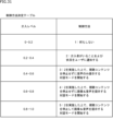
- FIG. 31 is a diagram illustrating an example of a control method determination table.
- control method 1 is performed.
- control method 2 is performed.
- control method 2 is performed first, and then control method 3 is performed.
- control method 2 is performed first, and then control method 4 is performed.
- control method 2 is performed first, and then control method 5 is performed.
- step S291 the camera 62 and microphone 71 sense the surrounding situation.
- step S292 the detection unit 72 detects human intervention (looking, approaching, speaking).
- step S293 the detection result presentation and inquiry unit 211 determines whether the setting is Auto or Manual. If it is determined in step S273 that the setting is to be automatically set, that is, that the setting is Auto, the process proceeds to step S294.
- step S294 the detection result presentation and inquiry unit 211 calculates the intervention level from the detection information, content information, and user information.
- step S295 the detection result presentation and inquiry unit 211 determines which control method the calculated intervention level corresponds to. If it is determined in step S295 that it corresponds to control method 1, the second control process in FIG. 30 ends.
- step S295 If it is determined in step S295 that the control method 2 is supported, the process proceeds to step S296.
- step S296 the detection result presentation and inquiry unit 211 notifies the user of the detection result. After that, the second control process in FIG. 30 ends.
- step S295 If it is determined in step S295 that the control method corresponds to control methods 3 to 5, processing proceeds to step S299.
- step S293 if the control method is confirmed and set by the user in step S293, i.e., if it is determined to be Manual, processing proceeds to step S297.
- step S297 the detection result presentation and inquiry unit 211 notifies the user of the detection result and inquires about a control method.
- step S298 the detection result presentation and inquiry unit 211 determines which control method the user selected. Note that in the example of FIG. 30, since notification is mandatory, control method 1 is not included as an option. If it is determined in step S298 that the user selected control method 2, the second control process in FIG. 30 ends.
- step S298 If it is determined in step S298 that the user has selected control method 3 to 5, processing proceeds to step S299.
- step S299 the extracted information superimposition unit 212 extracts the video and audio of the intervener from the video data and audio data, and the information presentation unit 74 presents the video and audio of the intervener on the presentation unit or in the VR space, and starts the dialogue mode according to the selected content (contents of the control method).
- the second control process in FIG. 30 ends.
- FIG. 32 is a diagram showing an example of a VR space that a user can view or experience.
- FIG. 32 shows a VR space 381 that the user views or experiences.
- the VR space 381 that is viewed or experienced by a user wearing the HMD 61-1 may be a locally deployed space.
- the VR space 381 may be a metaverse-like space deployed on a network in which multiple users participate, such as a user wearing HMD 61-1 and a user wearing HMD 61-2.
- This technology also targets a user wearing an HMD that operates in a dedicated application or game, etc., and intervention from another person in the real space in which the user is present.
- the device for viewing the VR space is not limited to an HMD, but can be any user device that blocks outside vision and sound when viewing the VR space, such as a VR headset.
- a VR headset is a headset used, for example, in VR that runs on a dedicated application or VR that runs on a dedicated game console.
- an external intervener is detected for a user wearing a user device that blocks outside vision and sound, and control is performed to present information about the detected intervener to the user.
- the above-mentioned series of processes can be executed by hardware or software.
- the program constituting the software is installed from a program recording medium into a computer incorporated in dedicated hardware, or into a general-purpose personal computer, etc.
- FIG. 33 is a block diagram showing an example of the hardware configuration of a computer 900 that executes the above-mentioned series of processes by a program.
- the CPU Central Processing Unit
- ROM Read Only Memory
- RAM Random Access Memory
- an input/output interface 910 Connected to the input/output interface 910 are an input unit 911 consisting of a keyboard, mouse, etc., and an output unit 912 consisting of a display, speakers, etc. Also connected to the input/output interface 910 are a storage unit 913 consisting of a hard disk or non-volatile memory, a communication unit 914 consisting of a network interface, etc., and a drive 915 that drives a removable recording medium 921.
- the CPU 901 for example, loads a program stored in the storage unit 913 into the RAM 903 via the input/output interface 910 and the bus 904 and executes the program, thereby performing the above-mentioned series of processes.
- the programs executed by the CPU 901 are recorded on, for example, a removable recording medium 921, or are provided via a wired or wireless transmission medium such as a local area network, the Internet, or digital broadcasting, and are installed in the storage unit 913.
- the program executed by the computer may be a program in which processing is performed chronologically in the order described in this specification, or a program in which processing is performed in parallel or at the required timing, such as when called.
- a system refers to a collection of multiple components (devices, modules (parts), etc.), regardless of whether all the components are in the same housing. Therefore, multiple devices housed in separate housings and connected via a network, and a single device in which multiple modules are housed in a single housing, are both systems.
- this technology can be configured as cloud computing, in which a single function is shared and processed collaboratively by multiple devices over a network.
- each step described in the above flowchart can be executed by a single device, or can be shared and executed by multiple devices.
- a single step includes multiple processes
- the processes included in that single step can be executed by a single device, or can be shared and executed by multiple devices.
- the present technology can also be configured as follows.
- a detection unit that detects an external intervener with respect to a user wearing a user device in which external visibility and sound are blocked; and a presentation control unit that controls presentation of information about the detected intervention person to the user.
- the presentation control unit performs control to present, as information regarding the intervention person, notification information notifying the presence of the intervention person.
- the presentation control unit performs control to present at least one of an image of the intervention person, an avatar of the intervention person, and a voice of the intervention person as the information regarding the intervention person.
- the information processing device determines whether or not to respond to the intervention person in accordance with a selection by the user.
- a correspondence storage unit is provided for storing information indicating whether each of the intervention persons can respond.
- the information processing device determines whether or not to respond to the intervention person according to information indicating whether or not a response can be made for each intervention person.
- the information processing device determines whether or not to respond to the intervention person depending on an intervention level.
- the information processing device includes at least one of an action of talking to the user, an action of approaching the user, or an action of looking at the user.
- the degree of intervention by the interventionist includes at least one of the distance when approaching the user, the speed at which the interventionist approaches the user, or the volume of the voice at which the interventionist speaks to the user.
- the intervention level is set according to at least one of an attribute of the user and an attribute of the intervention person.
- the attribute is an adult or a child.
- the information processing device is set according to a type of content being viewed by the user.
- the detection unit detects the intervener using at least one of video data captured and generated by an imaging unit and audio data collected and generated by an audio collection unit.
- the imaging unit and the sound collection unit are provided in the user device.
- the user device is a head mounted display.
- An information processing device, An information processing method comprising: detecting an external intervener in a user wearing a device that blocks outside vision and sound; and controlling the presentation of information about the detected intervener to the user.
Landscapes
- Engineering & Computer Science (AREA)
- General Engineering & Computer Science (AREA)
- Theoretical Computer Science (AREA)
- Multimedia (AREA)
- Signal Processing (AREA)
- General Physics & Mathematics (AREA)
- Physics & Mathematics (AREA)
- Human Computer Interaction (AREA)
- Computer Networks & Wireless Communication (AREA)
- Databases & Information Systems (AREA)
- Ecology (AREA)
- Environmental Sciences (AREA)
- Remote Sensing (AREA)
- Environmental & Geological Engineering (AREA)
- Emergency Management (AREA)
- Biodiversity & Conservation Biology (AREA)
- Life Sciences & Earth Sciences (AREA)
- Business, Economics & Management (AREA)
- User Interface Of Digital Computer (AREA)
Priority Applications (3)
| Application Number | Priority Date | Filing Date | Title |
|---|---|---|---|
| CN202480020756.4A CN120917759A (zh) | 2023-05-01 | 2024-04-15 | 信息处理装置、方法和程序 |
| KR1020257039310A KR20260008109A (ko) | 2023-05-01 | 2024-04-15 | 정보 처리 장치, 방법 및 프로그램 |
| JP2025518121A JPWO2024228329A1 (https=) | 2023-05-01 | 2024-04-15 |
Applications Claiming Priority (2)
| Application Number | Priority Date | Filing Date | Title |
|---|---|---|---|
| JP2023-075470 | 2023-05-01 | ||
| JP2023075470 | 2023-05-01 |
Publications (1)
| Publication Number | Publication Date |
|---|---|
| WO2024228329A1 true WO2024228329A1 (ja) | 2024-11-07 |
Family
ID=93333029
Family Applications (1)
| Application Number | Title | Priority Date | Filing Date |
|---|---|---|---|
| PCT/JP2024/014972 Ceased WO2024228329A1 (ja) | 2023-05-01 | 2024-04-15 | 情報処理装置、方法、およびプログラム |
Country Status (4)
| Country | Link |
|---|---|
| JP (1) | JPWO2024228329A1 (https=) |
| KR (1) | KR20260008109A (https=) |
| CN (1) | CN120917759A (https=) |
| WO (1) | WO2024228329A1 (https=) |
Citations (5)
| Publication number | Priority date | Publication date | Assignee | Title |
|---|---|---|---|---|
| US20180005429A1 (en) * | 2016-06-30 | 2018-01-04 | Sony Interactive Entertainment Inc. | Dynamic Entering and Leaving of Virtual-Reality Environments Navigated by Different HMD Users |
| US20180097975A1 (en) * | 2016-09-30 | 2018-04-05 | Sony Interactive Entertainment Inc. | Systems and methods for reducing an effect of occlusion of a tracker by people |
| US20180093186A1 (en) * | 2016-09-30 | 2018-04-05 | Sony Interactive Entertainment Inc. | Methods for Providing Interactive Content in a Virtual Reality Scene to Guide an HMD User to Safety Within a Real World Space |
| JP2018067156A (ja) * | 2016-10-19 | 2018-04-26 | キヤノン株式会社 | 通信装置およびその制御方法 |
| JP2018113616A (ja) * | 2017-01-12 | 2018-07-19 | ソニー株式会社 | 情報処理装置、情報処理方法、およびプログラム |
Family Cites Families (1)
| Publication number | Priority date | Publication date | Assignee | Title |
|---|---|---|---|---|
| JP5580855B2 (ja) | 2012-06-12 | 2014-08-27 | 株式会社ソニー・コンピュータエンタテインメント | 障害物回避装置および障害物回避方法 |
-
2024
- 2024-04-15 CN CN202480020756.4A patent/CN120917759A/zh active Pending
- 2024-04-15 WO PCT/JP2024/014972 patent/WO2024228329A1/ja not_active Ceased
- 2024-04-15 JP JP2025518121A patent/JPWO2024228329A1/ja active Pending
- 2024-04-15 KR KR1020257039310A patent/KR20260008109A/ko active Pending
Patent Citations (5)
| Publication number | Priority date | Publication date | Assignee | Title |
|---|---|---|---|---|
| US20180005429A1 (en) * | 2016-06-30 | 2018-01-04 | Sony Interactive Entertainment Inc. | Dynamic Entering and Leaving of Virtual-Reality Environments Navigated by Different HMD Users |
| US20180097975A1 (en) * | 2016-09-30 | 2018-04-05 | Sony Interactive Entertainment Inc. | Systems and methods for reducing an effect of occlusion of a tracker by people |
| US20180093186A1 (en) * | 2016-09-30 | 2018-04-05 | Sony Interactive Entertainment Inc. | Methods for Providing Interactive Content in a Virtual Reality Scene to Guide an HMD User to Safety Within a Real World Space |
| JP2018067156A (ja) * | 2016-10-19 | 2018-04-26 | キヤノン株式会社 | 通信装置およびその制御方法 |
| JP2018113616A (ja) * | 2017-01-12 | 2018-07-19 | ソニー株式会社 | 情報処理装置、情報処理方法、およびプログラム |
Also Published As
| Publication number | Publication date |
|---|---|
| CN120917759A (zh) | 2025-11-07 |
| JPWO2024228329A1 (https=) | 2024-11-07 |
| KR20260008109A (ko) | 2026-01-15 |
Similar Documents
| Publication | Publication Date | Title |
|---|---|---|
| US11736880B2 (en) | Switching binaural sound | |
| US11100694B2 (en) | Virtual reality presentation of eye movement and eye contact | |
| KR20220123576A (ko) | 3차원(3d) 환경에 대한 통합된 입/출력 | |
| US12436977B2 (en) | Apparatus, systems and methods for providing conversational assistance | |
| CN114845081A (zh) | 信息处理装置、记录介质及信息处理方法 | |
| US20220131979A1 (en) | Methods and systems for automatic queuing in conference calls | |
| WO2008150427A1 (en) | Multi-camera residential communication system | |
| JP2009077380A (ja) | 画像修正方法、画像修正システム、及び画像修正プログラム | |
| WO2008153822A2 (en) | A residential video communication system | |
| JP7851588B2 (ja) | 端末、情報処理方法、プログラム、および記録媒体 | |
| CN109804407B (zh) | 关心维持系统以及服务器 | |
| US11164341B2 (en) | Identifying objects of interest in augmented reality | |
| TW201707444A (zh) | 視線校正(一) | |
| JPWO2019155735A1 (ja) | 情報処理装置、情報処理方法及びプログラム | |
| US12347235B2 (en) | Establishing private communication channels | |
| Danninger et al. | The connector: facilitating context-aware communication | |
| WO2024228329A1 (ja) | 情報処理装置、方法、およびプログラム | |
| CN112162638B (zh) | 一种虚拟现实vr观影中的信息处理方法及服务器 | |
| JP7792533B2 (ja) | 映像表示装置、映像表示システム及び映像表示装置の制御方法 | |
| JP7756446B2 (ja) | 動画像分析システム | |
| JP7734990B2 (ja) | 動画像分析システム | |
| JP7734987B2 (ja) | 動画像分析システム |
Legal Events
| Date | Code | Title | Description |
|---|---|---|---|
| 121 | Ep: the epo has been informed by wipo that ep was designated in this application |
Ref document number: 24800060 Country of ref document: EP Kind code of ref document: A1 |
|
| WWE | Wipo information: entry into national phase |
Ref document number: 202480020756.4 Country of ref document: CN |
|
| ENP | Entry into the national phase |
Ref document number: 2025518121 Country of ref document: JP Kind code of ref document: A |
|
| WWE | Wipo information: entry into national phase |
Ref document number: 2025518121 Country of ref document: JP |
|
| WWP | Wipo information: published in national office |
Ref document number: 202480020756.4 Country of ref document: CN |
|
| ENP | Entry into the national phase |
Ref document number: 1020257039310 Country of ref document: KR Free format text: ST27 STATUS EVENT CODE: A-0-1-A10-A15-NAP-PA0105 (AS PROVIDED BY THE NATIONAL OFFICE) |
|
| NENP | Non-entry into the national phase |
Ref country code: DE |