WO2024228251A1 - 位置推定方法、位置推定プログラムおよび情報処理装置 - Google Patents
位置推定方法、位置推定プログラムおよび情報処理装置 Download PDFInfo
- Publication number
- WO2024228251A1 WO2024228251A1 PCT/JP2023/017138 JP2023017138W WO2024228251A1 WO 2024228251 A1 WO2024228251 A1 WO 2024228251A1 JP 2023017138 W JP2023017138 W JP 2023017138W WO 2024228251 A1 WO2024228251 A1 WO 2024228251A1
- Authority
- WO
- WIPO (PCT)
- Prior art keywords
- frame
- orientation
- estimating
- estimated
- camera
- Prior art date
- Legal status (The legal status is an assumption and is not a legal conclusion. Google has not performed a legal analysis and makes no representation as to the accuracy of the status listed.)
- Ceased
Links
Images




Classifications
-
- G—PHYSICS
- G06—COMPUTING OR CALCULATING; COUNTING
- G06T—IMAGE DATA PROCESSING OR GENERATION, IN GENERAL
- G06T7/00—Image analysis
- G06T7/70—Determining position or orientation of objects or cameras
Definitions
- the present invention relates to a position estimation method, a position estimation program, and an information processing device.
- a device estimates the state (position and posture) in three-dimensional space of objects or people captured in captured video based on the captured video. For example, a device has been proposed that estimates an initial posture based on joint feature data and a motion model of a multi-joint object, generates a motion vector based on the estimated information, and estimates the most likely posture from among the postures included in the state samples for each viewpoint candidate selected based on the motion vector.
- the state is estimated using depth information in addition to video images.
- a device has been proposed that extracts three-dimensional mesh information from a depth image and compares the three-dimensional coordinates of the three-dimensional mesh information with the object recognition results from a color image to extract the three-dimensional coordinates of the object.
- the present invention aims to provide a position estimation method, a position estimation program, and an information processing device that can estimate the three-dimensional position of a person with high accuracy from a video image captured by a moving camera.
- One proposal provides a position estimation method in which a computer executes the following process.
- the computer executes a coordinate estimation process to estimate a first position and orientation of the camera for each of a plurality of frames included in a video image in which a person is captured by the camera, and to estimate first three-dimensional absolute coordinates for each of a plurality of joints included in the person based on the first position and orientation.
- the coordinate estimation process for a first frame of the plurality of frames includes the following first to third processes.
- the computer estimates a second position and orientation of the camera corresponding to the first frame based on the positional relationship of the plurality of joints between the first frame and a second frame preceding the first frame, and the first position and orientation estimated from the second frame.
- the computer estimates a joint torque acting on each of the plurality of joints in the first frame based on the positional relationship, and estimates a trajectory of each of the plurality of joints from the second frame based on the joint torque.
- the computer estimates a first position and orientation corresponding to the first frame by correcting the second position and orientation based on the trajectory estimation result, and estimates first three-dimensional absolute coordinates for each of the multiple joints corresponding to the first frame based on the estimated first position and orientation.
- the three-dimensional position of a person can be estimated with high accuracy from a moving image captured by a moving camera.
- FIG. 2 is a diagram illustrating a configuration example and a processing example of a first information processing system.
- FIG. 13 illustrates an example of a configuration of an information processing system according to a second embodiment.
- FIG. 13 is a diagram for explaining a problem that occurs when a person moves within a frame.
- FIG. 2 is a diagram illustrating an example of a configuration of processing functions included in an information processing device.
- FIG. 13 is a diagram illustrating an outline of a process for estimating the global coordinates of each joint point.
- 11A and 11B are diagrams for explaining a contact surface detection process.
- 1 is a flowchart (part 1) illustrating an example of a process for estimating a three-dimensional position by an information processing device.
- 11 is a flowchart (part 2) illustrating an example of a process for estimating a three-dimensional position by the information processing device.
- First Embodiment 1 is a diagram showing an example of the configuration and processing of a first information processing system.
- the information processing system shown in FIG. 1 is a diagram showing an example of the configuration and processing of a first information processing system.
- the information processing system shown in FIG. 1 is a diagram showing an example of the configuration and processing of a first information processing system.
- the information processing system shown in FIG. 1 is a diagram showing an example of the configuration and processing of a first information processing system.
- Camera 1 captures video images of person 3.
- Camera 1 is also movable, for example by being carried by the photographer.
- Data of the captured video images is input to information processing device 2.
- the captured video image data may be input to information processing device 2 in real time when the video is captured, or may be temporarily stored in a storage device and then input to information processing device 2 at a timing asynchronous to the capture.
- the information processing device 2 has a processing unit 2a.
- the processing unit 2a is, for example, a processor.
- the processing unit 2a executes a coordinate estimation process that estimates first three-dimensional absolute coordinates for each of a plurality of joints included in the person 3 for each of the frames 4_1 to 4_N included in the input moving image.
- the processing unit 2a estimates a first position and orientation of the camera 1, and estimates the above-mentioned first three-dimensional absolute coordinates based on the estimated first position and orientation.
- the coordinate estimation process for each of frames 4_1 to 4_N includes the following steps S1 to S3.
- Mth (M ⁇ N) frame 4_M as an example.
- Step S1 The processing unit 2a estimates the second position and orientation of the camera 1 corresponding to frame 4_M based on the positional relationship of each joint between frame 4_M and the previous frame (here, the previous frame 4_M-1) and the first position and orientation estimated from frame 4_M-1.
- Step S2 The processing unit 2a estimates the joint torque acting on each joint in frame 4_M based on the positional relationship of each joint between frame 4_M and frame 4_M-1.
- the processing unit 2a estimates the trajectory of each joint from frame 4_M-1 based on the estimated joint torque. This trajectory estimation is performed, for example, by motion simulation.
- Step S3 Processing unit 2a estimates a first position and orientation corresponding to frame 4_M by correcting the second position and orientation estimated in step S1 based on the estimation results of the trajectories of each joint in step S2. Processing unit 2a estimates first three-dimensional absolute coordinates for each joint corresponding to frame 4_M based on the estimated first position and orientation.
- step S1 the second position and orientation of the camera 1 is estimated based on the video images captured by the movable camera 1.
- the estimation accuracy of the second position and orientation cannot be said to be high.
- processing unit 2a cannot determine whether the position of person 3 in space has moved upward due to an action such as a jump, or whether the position of camera 1 has moved downward. This makes it difficult to accurately estimate the second position and orientation. Therefore, it is difficult to estimate the three-dimensional absolute coordinates of each joint with high accuracy by using such a second position and orientation as is.
- the second position and orientation is corrected according to the movement of the person in space, thereby improving the estimation accuracy of the first position and orientation after correction.
- the second position and orientation will not change due to the correction.
- processing unit 2a can estimate the three-dimensional absolute position of each joint with high accuracy.
- Second Embodiment Fig. 2 is a diagram showing an example of the configuration of an information processing system according to the second embodiment.
- the information processing system shown in Fig. 2 includes an information processing device 100 and a camera 50 connected to the information processing device 100.
- the information processing device 100 is an example of the information processing device 2 shown in FIG. 1, and is realized as a computer such as a personal computer or a server device.
- the information processing device 100 estimates the three-dimensional coordinates of a person appearing in a video image based on the video image captured by the camera 50.
- the camera 50 is disposed so that it can be moved, for example by being carried by the photographer, and transmits data of the captured video image to the information processing device 100.
- the information processing device 100 receives the captured video data and estimates the three-dimensional coordinates of the person in real time.
- the captured video data may be temporarily stored in a storage device, and the information processing device 100 may estimate the three-dimensional coordinates of the person from the video data at a timing asynchronous to the capture.
- the information processing device 100 is realized, for example, as a computer with the hardware configuration shown in FIG. 2.
- the information processing device 100 shown in FIG. 2 has a processor 101, a RAM (Random Access Memory) 102, a HDD (Hard Disk Drive) 103, a GPU (Graphics Processing Unit) 104, an input interface (I/F) 105, a reading device 106, a communication interface (I/F) 107 and a network interface (I/F) 108.
- a processor 101 a RAM (Random Access Memory) 102, a HDD (Hard Disk Drive) 103, a GPU (Graphics Processing Unit) 104, an input interface (I/F) 105, a reading device 106, a communication interface (I/F) 107 and a network interface (I/F) 108.
- a processor 101 a RAM (Random Access Memory) 102, a HDD (Hard Disk Drive) 103, a GPU (Graphics Processing Unit) 104, an input interface (I/F) 105, a reading device 106, a communication interface
- the processor 101 provides overall control over the entire information processing device 100.
- the processor 101 may be, for example, a CPU (Central Processing Unit), an MPU (Micro Processing Unit), a DSP (Digital Signal Processor), an ASIC (Application Specific Integrated Circuit), or a PLD (Programmable Logic Device).
- the processor 101 may also be a combination of two or more elements of a CPU, MPU, DSP, ASIC, or PLD.
- RAM 102 is used as the main storage device of information processing device 100.
- RAM 102 temporarily stores at least a portion of the OS (Operating System) program and application programs to be executed by processor 101.
- RAM 102 also stores various types of data necessary for processing by processor 101.
- the HDD 103 is used as an auxiliary storage device for the information processing device 100.
- the OS program, application programs, and various data are stored in the HDD 103.
- non-volatile storage devices such as a solid state drive (SSD)
- SSD solid state drive
- a display device 104a is connected to the GPU 104.
- the GPU 104 displays an image on the display device 104a in accordance with instructions from the processor 101.
- the display device 104a may be a liquid crystal display or an organic EL (ElectroLuminescence) display.
- the input interface 105 is connected to an input device 105a.
- the input interface 105 transmits signals output from the input device 105a to the processor 101.
- Examples of the input device 105a include a keyboard and a pointing device.
- Examples of the pointing device include a mouse, a touch panel, a tablet, a touch pad, and a trackball.
- a portable recording medium 106a is detachably attached to the reading device 106.
- the reading device 106 reads data recorded on the portable recording medium 106a and transmits it to the processor 101.
- Examples of the portable recording medium 106a include an optical disk and a semiconductor memory.
- the communication interface 107 receives video data captured by the camera 50 and transmits it to the processor 101.
- the network interface 108 transmits and receives data to and from other devices via the network 108a. Note that video data from the camera 50 may be transmitted via the network 108a, and the network interface 108 may receive this data.
- the processing functions of the information processing device 100 can be realized by the above hardware configuration. Meanwhile, the information processing device 100 estimates the position and orientation of the movable camera 50 (hereinafter, may be referred to as the "camera position and orientation") from a moving image captured by the camera 50. Then, based on the estimated camera position and orientation, the information processing device 100 estimates three-dimensional coordinates in a global coordinate system of body parts (specifically, joint points) of a person appearing in the moving image.
- the information processing device 100 estimates the position and orientation of the movable camera 50 (hereinafter, may be referred to as the "camera position and orientation") from a moving image captured by the camera 50. Then, based on the estimated camera position and orientation, the information processing device 100 estimates three-dimensional coordinates in a global coordinate system of body parts (specifically, joint points) of a person appearing in the moving image.
- This configuration makes it possible to estimate the three-dimensional position of a person from a variety of captured images. For example, it becomes possible to estimate the three-dimensional positions of a person's body parts from video images of a person (athlete) during a sports broadcast or video images of a person (performer) at a concert. It also becomes possible to estimate the three-dimensional positions of a person's body parts from video images captured by a smartphone at such events.
- metaverse-related activities have become more active, such as watching events such as sports and concerts on the metaverse. If the three-dimensional positions of a person's body parts can be estimated using the above method, it will be possible to use this technology, for example, to recreate a real space in the metaverse and place an avatar corresponding to a photographed person in the recreated space.
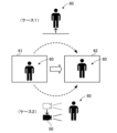
- Figure 3 is a diagram to explain the problems that arise when a person moves within a frame.
- the same person 60 appears in consecutive frames 61 and 62.
- the position of person 60 appears higher in frame 62 than in frame 61.
- person 60 appears to have moved upward in frame 62 compared to frame 61.
- Such a situation may occur, for example, in the following cases 1 and 2.
- case 1 the person 60 actually moves upward in space. For example, this is the case when the person 60 jumps.
- case 2 the person 60 does not move upward, and the camera 50 moves downward.
- it is difficult to accurately estimate the three-dimensional position of the person 60 because it is not possible to determine whether the person 60 or the camera 50 has moved, as described above.
- the information processing device 100 estimates the camera position and orientation based on the positional relationship of the person's joint points in the moving image, and also estimates the manner in which force is applied to the person based on this positional relationship.
- the information processing device 100 then optimizes the camera position and orientation and the manner in which force is applied so that the trajectory of the joint point in the global coordinate system predicted when the estimated force is applied matches the three-dimensional position of the joint point based on the camera position and orientation. This makes it possible to improve the estimation accuracy of the camera position and orientation, and by using the corrected camera position and orientation, it becomes possible to accurately estimate the three-dimensional coordinates of the joints in the global coordinate system.
- the information processing device 100 includes a storage unit 110 and a processing unit 120.
- the storage unit 110 is a storage area secured in a storage device included in the information processing device 100, such as the RAM 102 or the HDD 103.
- the storage unit 110 stores camera parameters 111, kinematic information 112, and a parameter set 113.
- the camera parameters 111 include information indicating internal parameters of the camera 50, such as the focal length and optical center of the camera 50.
- the kinematic information 112 is information that defines a joint model of a human.
- the kinematic information 112 includes information that indicates the connection relationship and relative positional relationship of a plurality of predetermined joint points.
- the kinematic information 112 may also include information that indicates the length of a part between adjacent joint points.
- the parameter set 113 includes various parameters used in the processing of the motion simulator 124 and the optimization processing unit 125.
- the parameter set 113 includes the coefficient of friction between the person and the contact surface, parameters for gradient calculation, and a convergence threshold value in the optimization calculation.
- the processing unit 120 includes a person detection unit 121, a contact surface detection unit 122, a camera position and orientation estimation unit 123, a motion simulator 124, and an optimization processing unit 125.
- the processing unit 120 is, for example, the processor 101.
- the processing of the person detection unit 121, the contact surface detection unit 122, the camera position and orientation estimation unit 123, the motion simulator 124, and the optimization processing unit 125 is realized, for example, by the processor 101 executing a predetermined program.
- the person detection unit 121 detects joint points included in the above joint model from the frames of the video image.
- the person detection unit 121 also estimates the three-dimensional coordinates of each detected joint point based on the positions of multiple joint points on the frame images, the relative positional relationships between the joint points based on the kinematic information 112, and the camera parameters 111.
- the estimated three-dimensional coordinates become coordinates in the camera coordinate system.
- the contact surface detection unit 122 detects the contact surface that is in contact with the person from the frame. For example, the contact surface detection unit 122 detects the ground or floor that is in contact with the joint point corresponding to the ankle as the contact surface. The contact surface detection unit 122 tracks the detected contact surface and estimates the three-dimensional coordinates of the contact surface based on the positional relationship of the contact surface between frames. The estimated three-dimensional coordinates are coordinates in the camera coordinate system.
- the camera position and orientation estimation unit 123 estimates the camera position and orientation based on the camera position and orientation estimated in the previous frame, the positional relationship between corresponding feature points in the previous frame, and the camera parameters 111. For example, joint points detected by the person detection unit 121 are used as feature points. In addition, by using the camera position and orientation estimated in the previous frame, time series prediction is performed from the initial position and orientation, so the camera position and orientation in the global coordinate system is estimated.
- the camera position and orientation estimation unit 123 uses the estimation result of the camera position and orientation to convert the three-dimensional coordinates of each joint point estimated by the person detection unit 121 and the three-dimensional coordinates of the contact surface estimated by the contact surface detection unit 122 into three-dimensional coordinates in the global coordinate system. In this way, the global coordinates of each joint point based on the camera position and orientation are estimated.
- the motion simulator 124 estimates mechanical parameters that indicate the forces acting on the person based on the positional relationship of the joint points and contact surfaces between frames.
- the estimated mechanical parameters include the joint torque acting on each joint point.
- the motion simulator 124 also estimates the three-dimensional coordinates in the global coordinate system of each joint point in the current frame by simulation, based on the three-dimensional coordinates of each joint point and contact surface in the global coordinate system estimated in the previous frame and the estimated mechanical parameters. This allows the global coordinates of each joint point to be estimated based on the simulation.
- the simulation is performed using a differentiable simulator (equation of motion) to enable gradient calculation in the optimization process.
- the optimization processing unit 125 optimizes the camera position and orientation and the joint torque so as to reduce the error between the global coordinates of each joint point estimated based on the camera position and orientation and the global coordinates of each joint point estimated based on the simulation.
- the optimization processing unit 125 outputs the global coordinates of each joint point in the current frame when the optimal value of the camera position and orientation is used.
- FIG. 5 is a diagram showing an overview of the process of estimating the global coordinates of each joint point.
- frame 72 is the target of processing.
- the human detection unit 121 detects the two-dimensional coordinates of each joint point of the person from frame 72, and estimates the three-dimensional coordinates of each detected joint point in the camera coordinate system.
- the camera position and orientation estimation unit 123 estimates the camera position and orientation corresponding to frame 72 based on the camera position and orientation estimated from frame 71 by the optimization processing unit 125, the positional relationship of each joint point between frames 71 and 72, and the camera parameters 111 (step S11).
- the camera position and orientation estimation unit 123 uses the estimated camera position and orientation to convert the three-dimensional coordinates of each joint point estimated by the person detection unit 121 into global coordinates (step S12).
- the motion simulator 124 estimates the joint torque acting on each joint point based on the positional relationship of the joint points between frames 71 and 72 (step S13).
- the motion simulator 124 estimates the global coordinates of each joint point in frame 72 by simulation based on the global coordinates of each joint point estimated from frame 71 and the estimated joint torque (step S14). This allows an estimate of the position in frame 72 to which the position of each joint point in the global coordinate system in frame 71 will move when the joint torque estimated in step S13 occurs.
- the optimization processing unit 125 compares the global coordinates estimated in step S12 with the global coordinates estimated in step S14.
- the optimization processing unit 125 optimizes the camera position and attitude and the joint torque so as to minimize the error in the global coordinates for each joint point (step S15). This calculates optimal values for the camera position and attitude and the joint torque that bring the global coordinate estimation results in steps S12 and S14 closer to the original values.
- This process estimates the camera position and attitude by reflecting not only geometric factors but also factors related to how forces are applied to the person. This makes it possible to accurately determine the movement of the camera 50 and the movement of the person and estimate the camera position and attitude.
- the optimization processing unit 125 estimates the global coordinates of each joint point based on the camera position and orientation optimized in step S15 (step S16). This improves the estimation accuracy of the global coordinates of each joint point.
- the accuracy of the estimation can be improved by also using the position of the contact surface that is in contact with the person.
- the contact surface for example, the surface of the object that is in contact with the lower end of the person, such as the ground or floor, is detected.
- FIG. 6 is a diagram for explaining the contact surface detection process, in which the left side of Fig. 6 shows the state of the previous frame, and the right side of Fig. 6 shows the state of the current frame.
- the contact surface detection unit 122 detects a contact surface from a certain frame
- the contact surface detection unit 122 continues to detect the position of the contact surface from the subsequent frames.
- the contact surface detection unit 122 tracks a plurality of feature points included in the detected contact surface. Such tracking is performed in parallel with the joint point detection process performed by the human detection unit 121.
- a contact surface 91 that is in contact with ankles 81, 82 among the joint points of a person is detected in the previous frame.
- the detected contact surface 91 is also detected in the current frame.
- in the current frame it is detected that ankles 81, 82 have left contact surface 91 by comparing the three-dimensional coordinates of ankles 81, 82 in the camera coordinate system with the three-dimensional coordinates of contact surface 91.
- the motion simulator 124 can calculate the distance between the joint point and the contact surface for each frame based on the estimation results of the three-dimensional coordinates of the joint point by the person detection unit 121 and the estimation results of the three-dimensional coordinates of the contact surface by the contact surface detection unit 122. Therefore, the motion simulator 124 can estimate not only the joint torque but also the reaction force and friction force from the contact surface to the joint point as motion parameters. Therefore, by using the three-dimensional coordinates of the contact surface, the motion simulator 124 can estimate the global coordinates of each joint point with high accuracy. For example, when a person in frame 62 moves upward as shown in FIG. 3, it can be accurately determined whether or not the person has moved upward from the lower contact surface.
- the contact surface detection unit 122 may not be able to continue to detect the same contact surface in all frames after the contact surface is detected. For example, there may be cases where the contact surface temporarily falls outside the shooting range, causing the contact surface detection unit 122 to be temporarily unable to detect the contact surface.
- the contact surface detection unit 122 estimates the position of the contact surface in the current frame by interpolation calculation from the detection results in past frames. Also, when the contact surface has not been detected by the current frame, the contact surface detection unit 122 may obtain position information of an external object that may come into contact with the person from past frames and estimate the position of the contact surface in the current frame by interpolation calculation. Also, when the process of FIG. 5 is executed in offline processing, the contact surface detection unit 122 may detect a contact surface that will come into contact with the person from a future frame and estimate the position of the contact surface in the current frame by interpolation calculation. Furthermore, when the contact surface is not captured in any frame, the contact surface detection unit 122 may estimate the distance between the contact surface and the person from the person's height and posture.
- FIG. 7 and 8 are flowcharts showing an example of a three-dimensional position estimation process performed by an information processing device.
- the human detection unit 121 acquires frame data from the input video. [Step S22] The human detection unit 121 detects a plurality of joint points of a human from the frame, and obtains the two-dimensional coordinates of these joint points.
- the person detection unit 121 estimates the three-dimensional coordinates of each detected joint point based on the two-dimensional coordinates of each joint point, the relative positional relationship between the joint points based on the kinematic information 112, and the camera parameters 111.
- the estimated three-dimensional coordinates become coordinates in the camera coordinate system.
- the contact surface detection unit 122 detects the contact surface that is in contact with the person from the frame.
- the contact surface detection unit 122 estimates the three-dimensional coordinates of the contact surface based on the positional relationship of the contact surface between the previous frame and the current frame.
- the estimated three-dimensional coordinates are coordinates in the camera coordinate system. In practice, for example, the three-dimensional coordinates of each feature point included in the current frame are estimated based on the positional relationship of corresponding feature points between frames among the feature points included in the contact surface.
- the camera position and orientation estimation unit 123 estimates the camera position and orientation corresponding to the current frame based on the camera position and orientation estimated from the previous frame by the optimization processing unit 125, the positional relationship of each joint point between the current frame and the previous frame, and the camera parameters 111.
- time series prediction from the initial position and orientation is performed, so the camera position and orientation in the global coordinate system is estimated.
- the estimated camera position and orientation becomes the initial parameter of the camera position and orientation in the optimization process.
- the camera position and orientation estimation unit 123 uses the estimated camera position and orientation to convert the three-dimensional coordinates of each joint point estimated by the person detection unit 121 into global coordinates.
- the camera position and orientation estimation unit 123 also uses the estimated camera position and orientation to convert the three-dimensional coordinates of the contact surface estimated by the contact surface detection unit 122 into global coordinates.
- Step S27 The motion simulator 124 acquires the three-dimensional coordinates of each joint point for the current frame estimated by the person detection unit 121 in step S23.
- the motion simulator 124 also acquires the three-dimensional coordinates of the contact surface for the current frame estimated by the contact surface detection unit 122 in step S24.
- the motion simulator 124 acquires the three-dimensional coordinates of each joint point for the previous frame, which are estimated by the person detection unit 121 in step S23 for the previous frame. Also, the motion simulator 124 acquires the three-dimensional coordinates of the contact surface, which are estimated by the contact surface detection unit 122 in step S24 for the previous frame.
- the motion simulator 124 uses the acquired three-dimensional coordinates to estimate mechanical parameters that indicate the forces acting on the person in the current frame, based on the positional relationship of corresponding joint points and the positional relationship of contact surfaces between the current frame and the previous frame.
- Estimated mechanical parameters include, for example, the joint torque acting on each joint point, the reaction force from the contact surface to the person, and the frictional force between the contact surface and the person.
- the estimated joint torque becomes the initial parameter of the joint torque in the optimization process.
- Step S28 The motion simulator 124 acquires the three-dimensional coordinates of each joint point and contact surface in the global coordinate system estimated by the optimization processing unit 125 for the previous frame, and the mechanical parameters corresponding to the current frame estimated in step S27. Based on the acquired information, the motion simulator 124 estimates the global coordinates of each joint point for the current frame through simulation.
- Step S29 The optimization processor 125 generates an objective function f for optimization.
- the objective function f is expressed by, for example, the following formula (1).
- T is a position and orientation matrix indicating the camera position and orientation estimated in step S25.
- F n indicates the joint torque estimated in step S27 for the n-th joint point.
- x n indicates the three-dimensional coordinate estimated in step S26 for the n-th joint point.
- rn indicates the three-dimensional coordinate estimated in step S27 for the n-th joint point.
- rn ( ⁇ F m ⁇ m ) means that when the estimated joint torque acts on m joint points (all joint points), the three-dimensional coordinate rn of the n-th joint point is obtained by solving the equation of motion. Note that the calculation of rn ( ⁇ F m ⁇ m ) is performed by the motion simulator 124.
- n 0a indicates the position and orientation of the contact surface in global coordinates estimated in the previous frame.
- n a indicates the position and orientation of the contact surface in global coordinates estimated in the current frame.
- F 0n indicates a time-series predicted value of the joint torque for the n-th joint point (e.g., the joint torque estimated in the previous frame).
- T 0 indicates a time-series predicted value of the camera position and orientation (e.g., the camera position and orientation estimated in the previous frame).
- tr indicates the trace of the matrix (the sum of the diagonal components).
- w c , w rF , and w rT indicate weighting coefficients that are set in advance.
- the first term in equation (1) indicates the error between the global coordinates of each joint point estimated in step S26 and the global coordinates of each joint point estimated in step S28.
- the second term in equation (1) indicates the error in the contact surface estimation result between the previous frame and the current frame.
- the third term in equation (1) is a smoothing term to suppress sudden torque fluctuations between frames.
- step S29 When step S29 is executed after step S28, the camera position and orientation and the joint torque, which are the parameters to be optimized, are set as initial values estimated in steps S25 and S27, respectively.
- step S29 is executed after step S31, the camera position and orientation and the joint torque are set as values updated in the most recent step S30.
- the optimization processor 125 executes a gradient calculation of the objective function f.
- this gradient calculation for example, a Jacobian matrix is used.
- the optimization processor 125 obtains the amounts of change in each of the camera position and orientation and the joint torque based on the result of the gradient calculation in step S29.
- the optimization processor 125 adds the obtained amounts of change to the current values of the camera position and orientation and the joint torque to update the values of the camera position and orientation and the joint torque.
- Step S31 The optimization processor 125 inputs the camera position and orientation and the joint torque values updated in step S30 into equation (1) and recalculates equation (1).
- the global coordinates of each joint point and contact surface based on the updated camera position and orientation are recalculated by the camera position and orientation estimation unit 123 in response to an instruction from the optimization processor 125.
- the calculation of r n ( ⁇ F m ⁇ m ) is recalculated by the motion simulator 124 in response to an instruction from the optimization processor 125.
- the optimization processing unit 125 determines whether the calculation of formula (1) has converged. For example, if the calculated value of formula (1) is equal to or less than a predetermined threshold, it is determined that the calculation has converged. If the calculation has not converged, the process proceeds to step S29, and if the calculation has converged, the process proceeds to step S32.
- Step S32 The optimization processing unit 125 finally outputs the global coordinates of each joint point calculated in step S30 (i.e., the global coordinates of each joint point estimated using the optimal camera position and orientation) as the global coordinates of each joint point corresponding to the frame acquired in step S21.
- Step S33 The optimization processing unit 125 determines whether the frame acquired in step S21 is the final frame in the video. If it is not the final frame, the process proceeds to step S21, where the next frame is acquired. On the other hand, if it is the final frame, the process ends.
- the optimization process also optimizes the joint torques in the above mentioned optimization process. This reduces the effect of joint torque calculation errors and improves the final estimation accuracy of the global coordinates of each joint point. For example, depending on the orientation of the person in the frame, one joint point may be hidden by another joint point, making it impossible to detect the former joint point, which may result in a decrease in the estimation accuracy of the joint torque.
- optimizing the joint torques as described above it is possible to reduce the impact of such a decrease in estimation accuracy on the estimation accuracy of the global coordinates of each joint point.
- the processing functions of the devices can be realized by a computer.
- a program describing the processing contents of the functions that each device should have is provided, and the above processing functions are realized on the computer by executing the program on a computer.
- the program describing the processing contents can be recorded on a computer-readable recording medium.
- Examples of computer-readable recording media include magnetic storage devices, optical discs, and semiconductor memories. Examples of magnetic storage devices include hard disk drives (HDDs) and magnetic tapes. Examples of optical discs include CDs (Compact Discs), DVDs (Digital Versatile Discs), and Blu-ray Discs (BD, registered trademark).
- portable recording media such as DVDs or CDs on which the program is recorded are sold.
- the program can also be stored in a storage device of a server computer, and the program can be transferred from the server computer to other computers via a network.
- a computer that executes a program stores, for example, a program recorded on a portable recording medium or a program transferred from a server computer in its own storage device. The computer then reads the program from its own storage device and executes processing in accordance with the program. The computer can also read a program directly from a portable recording medium and execute processing in accordance with that program. The computer can also execute processing in accordance with the received program each time a program is transferred from a server computer connected via a network.
Landscapes
- Engineering & Computer Science (AREA)
- Computer Vision & Pattern Recognition (AREA)
- Physics & Mathematics (AREA)
- General Physics & Mathematics (AREA)
- Theoretical Computer Science (AREA)
- Image Analysis (AREA)
Priority Applications (2)
| Application Number | Priority Date | Filing Date | Title |
|---|---|---|---|
| PCT/JP2023/017138 WO2024228251A1 (ja) | 2023-05-02 | 2023-05-02 | 位置推定方法、位置推定プログラムおよび情報処理装置 |
| JP2025518074A JPWO2024228251A1 (https=) | 2023-05-02 | 2023-05-02 |
Applications Claiming Priority (1)
| Application Number | Priority Date | Filing Date | Title |
|---|---|---|---|
| PCT/JP2023/017138 WO2024228251A1 (ja) | 2023-05-02 | 2023-05-02 | 位置推定方法、位置推定プログラムおよび情報処理装置 |
Publications (1)
| Publication Number | Publication Date |
|---|---|
| WO2024228251A1 true WO2024228251A1 (ja) | 2024-11-07 |
Family
ID=93332978
Family Applications (1)
| Application Number | Title | Priority Date | Filing Date |
|---|---|---|---|
| PCT/JP2023/017138 Ceased WO2024228251A1 (ja) | 2023-05-02 | 2023-05-02 | 位置推定方法、位置推定プログラムおよび情報処理装置 |
Country Status (2)
| Country | Link |
|---|---|
| JP (1) | JPWO2024228251A1 (https=) |
| WO (1) | WO2024228251A1 (https=) |
Cited By (1)
| Publication number | Priority date | Publication date | Assignee | Title |
|---|---|---|---|---|
| CN119366911A (zh) * | 2024-12-31 | 2025-01-28 | 浙江大学 | 一种应用于人本智造的姿势矫正训练方法和装置 |
Citations (2)
| Publication number | Priority date | Publication date | Assignee | Title |
|---|---|---|---|---|
| JP2012518857A (ja) * | 2009-02-25 | 2012-08-16 | 本田技研工業株式会社 | 内側距離形状関係を使用する身体特徴検出及び人間姿勢推定 |
| WO2021090467A1 (ja) * | 2019-11-08 | 2021-05-14 | 日本電信電話株式会社 | カメラパラメータ推定装置、カメラパラメータ推定方法及びカメラパラメータ推定プログラム |
-
2023
- 2023-05-02 WO PCT/JP2023/017138 patent/WO2024228251A1/ja not_active Ceased
- 2023-05-02 JP JP2025518074A patent/JPWO2024228251A1/ja active Pending
Patent Citations (2)
| Publication number | Priority date | Publication date | Assignee | Title |
|---|---|---|---|---|
| JP2012518857A (ja) * | 2009-02-25 | 2012-08-16 | 本田技研工業株式会社 | 内側距離形状関係を使用する身体特徴検出及び人間姿勢推定 |
| WO2021090467A1 (ja) * | 2019-11-08 | 2021-05-14 | 日本電信電話株式会社 | カメラパラメータ推定装置、カメラパラメータ推定方法及びカメラパラメータ推定プログラム |
Non-Patent Citations (1)
| Title |
|---|
| TAKAHASHI, KOSUKE, MIKAMI DAN, ISOGAWA MARIKO, KIMATA HIDEAKI: "Extrinsic Camera Calibration from Human Joints", ISPJ SIG TECHNICAL REPORT (CVIM), vol. 2017, no. 30, 9 November 2017 (2017-11-09), XP093231229 * |
Cited By (1)
| Publication number | Priority date | Publication date | Assignee | Title |
|---|---|---|---|---|
| CN119366911A (zh) * | 2024-12-31 | 2025-01-28 | 浙江大学 | 一种应用于人本智造的姿势矫正训练方法和装置 |
Also Published As
| Publication number | Publication date |
|---|---|
| JPWO2024228251A1 (https=) | 2024-11-07 |
Similar Documents
| Publication | Publication Date | Title |
|---|---|---|
| US8602887B2 (en) | Synthesis of information from multiple audiovisual sources | |
| US10394318B2 (en) | Scene analysis for improved eye tracking | |
| JP7003628B2 (ja) | 物体追跡プログラム、物体追跡装置、及び物体追跡方法 | |
| US12165358B2 (en) | Main subject determining apparatus, image capturing apparatus, main subject determining method, and storage medium | |
| US10003722B2 (en) | Method and system for mimicking human camera operation | |
| CN109255749B (zh) | 自主和非自主平台中的地图构建优化 | |
| JP2012151796A (ja) | 画像処理装置と画像処理方法およびプログラム | |
| US11403768B2 (en) | Method and system for motion prediction | |
| KR20140034847A (ko) | 관절로 연결된 모델의 전자동 동적 교정 기법 | |
| US20230135628A1 (en) | Signal processing device, signal processing method, and parameter search method | |
| KR102539215B1 (ko) | 골프 스윙에 관한 정보를 추정하기 위한 방법, 디바이스 및 비일시성의 컴퓨터 판독 가능한 기록 매체 | |
| KR20220086971A (ko) | 손 관절을 추적하는 방법 및 장치 | |
| JP2025128345A (ja) | ゴルフスイングに関する情報を推定するための方法、デバイスおよび非一過性のコンピュータ読み取り可能な記録媒体 | |
| WO2023179342A1 (zh) | 重定位方法及相关设备 | |
| WO2024228251A1 (ja) | 位置推定方法、位置推定プログラムおよび情報処理装置 | |
| KR20230124852A (ko) | 골프 스윙 자세에 관한 정보를 추정하기 위한 방법,시스템 및 비일시성의 컴퓨터 판독 가능한 기록 매체 | |
| US20230177860A1 (en) | Main object determination apparatus, image capturing apparatus, and method for controlling main object determination apparatus | |
| US11398047B2 (en) | Virtual reality simulations using surface tracking | |
| US20230156331A1 (en) | Signal processing device and signal processing method | |
| CN111489376B (zh) | 跟踪交互设备的方法、装置、终端设备及存储介质 | |
| KR20250110116A (ko) | 데이터 수집 시스템 및 데이터 수집 방법 | |
| JP7782562B2 (ja) | 情報処理装置、情報処理方法およびプログラム | |
| US11836879B2 (en) | Information processing apparatus, information processing method, and storage medium for correcting a shift between three-dimensional positions | |
| JP2023161440A (ja) | 映像処理装置及びその制御方法及びプログラム | |
| EP2990085B1 (en) | Method and apparatus for estimating the value of an input in presence of a perturbing factor |
Legal Events
| Date | Code | Title | Description |
|---|---|---|---|
| 121 | Ep: the epo has been informed by wipo that ep was designated in this application |
Ref document number: 23935764 Country of ref document: EP Kind code of ref document: A1 |
|
| ENP | Entry into the national phase |
Ref document number: 2025518074 Country of ref document: JP Kind code of ref document: A |
|
| WWE | Wipo information: entry into national phase |
Ref document number: 2025518074 Country of ref document: JP |
|
| NENP | Non-entry into the national phase |
Ref country code: DE |