WO2024225434A1 - 弁ゴム式電磁弁 - Google Patents
弁ゴム式電磁弁 Download PDFInfo
- Publication number
- WO2024225434A1 WO2024225434A1 PCT/JP2024/016426 JP2024016426W WO2024225434A1 WO 2024225434 A1 WO2024225434 A1 WO 2024225434A1 JP 2024016426 W JP2024016426 W JP 2024016426W WO 2024225434 A1 WO2024225434 A1 WO 2024225434A1
- Authority
- WO
- WIPO (PCT)
- Prior art keywords
- valve
- rubber
- valve rubber
- core
- seating surface
- Prior art date
- Legal status (The legal status is an assumption and is not a legal conclusion. Google has not performed a legal analysis and makes no representation as to the accuracy of the status listed.)
- Ceased
Links
Images





Classifications
-
- F—MECHANICAL ENGINEERING; LIGHTING; HEATING; WEAPONS; BLASTING
- F16—ENGINEERING ELEMENTS AND UNITS; GENERAL MEASURES FOR PRODUCING AND MAINTAINING EFFECTIVE FUNCTIONING OF MACHINES OR INSTALLATIONS; THERMAL INSULATION IN GENERAL
- F16K—VALVES; TAPS; COCKS; ACTUATING-FLOATS; DEVICES FOR VENTING OR AERATING
- F16K31/00—Actuating devices; Operating means; Releasing devices
- F16K31/02—Actuating devices; Operating means; Releasing devices electric; magnetic
- F16K31/06—Actuating devices; Operating means; Releasing devices electric; magnetic using a magnet, e.g. diaphragm valves, cutting off by means of a liquid
Definitions
- the present invention relates to a rubber solenoid valve used to control the flow/cut-off of a fluid, such as printing ink.
- a conventional diaphragm type solenoid valve (an example of a rubber valve type solenoid valve) includes a main body 110 having a diaphragm seating surface 112 to which flow paths 110a, 110b open, a diaphragm 123 arranged to seat on the diaphragm seating surface 112 of the main body 110, a diaphragm boss 122 that holds the diaphragm 123, a moving core (not shown in FIG. 14) that holds the diaphragm boss 122, and an electromagnetic force application section (not shown in FIG. 14) that applies an electromagnetic force to the moving core, moving the moving core in a direction away from the diaphragm seating surface 112 of the main body 110, thereby moving the diaphragm 123 away from the diaphragm seating surface 112.
- the diaphragm boss 122 has a large diameter surrounded main body portion 122m surrounded by the diaphragm 123 and a small diameter portion 122e extending upward from the center of the surrounded main body portion 122m
- the diaphragm 123 has a diaphragm boss surrounding portion 123c surrounding the lower region of the surrounded main body portion 122m and the small diameter portion 122e, a thin-walled portion 123b extending annularly outside the diaphragm boss surrounding portion 123c, and a thick-walled outer peripheral portion 123a extending annularly further outside the thin-walled portion 123b.
- the surrounded main body portion 122m and the lower area of the small diameter portion 122e of the diaphragm boss 122 and the diaphragm boss surrounding portion 123c of the diaphragm 123 are adapted to be engaged (and removed) manually by an operator using the elastic deformation of the diaphragm boss surrounding portion 123c.
- the thin-walled portion 123b is used to elastically deform the diaphragm 123, but the durability of the thin-walled portion 123b can be an issue.
- the applicant has also developed a diaphragm-type solenoid valve in which the diaphragm boss does not fall off the diaphragm when the moving core rises. Specifically, the applicant has developed a technology to integrate the diaphragm with the diaphragm boss by baking (JP Patent Publication 2020-076437 (Patent Document 1)).
- the deformation of the diaphragm 123 is borne by the thin-walled portion 123b that extends annularly outside the diaphragm boss surrounding portion 123c.
- the present invention was created based on the above findings.
- the purpose of the present invention is to provide a new configuration for a rubber valve type solenoid valve with excellent durability.
- the first aspect of the present invention is a rubber valve type solenoid valve including a main body having a rubber valve seating surface on which at least one flow path is opened, a rubber valve arranged to seat on the rubber valve seating surface of the main body, a retaining core that holds the rubber valve at one end, a moving core connected to the other end of the retaining core, and an electromagnetic force application unit that applies an electromagnetic force to the moving core and moves the moving core and the retaining core relative to the rubber valve seating surface of the main body, thereby moving the rubber valve relative to the rubber valve seating surface
- the valve has an opening closing surface portion, a cylindrical portion extending from the opening closing surface portion toward the retaining core, and a flange portion extending annularly outward from the end of the cylindrical portion on the retaining core side, and the outer peripheral area of the flange portion is fixed to the main body portion, and the opening closing surface portion is fixed to the retaining core (for example, by a vulcanizing adhesive or by a fitting-type fixing method), while the cylindrical portion is not
- the elastic deformation of the valve rubber is achieved by utilizing the expansion and contraction deformation of the tubular portion, so there is no need to provide a thin-walled portion. This makes it possible to fundamentally resolve durability issues caused by the presence of thin-walled portions.
- the flange portion does not need to have a so-called thin-walled portion. From the viewpoint of durability, it is preferable that the flange portion has a thickness of 0.5 mm or more at any position. Accordingly, from the viewpoint of practical durability, it is preferable that the flange portion has a thickness of 0.4 mm or more.
- the opening closing surface of the valve rubber and the retaining core are fixed (for example, by a vulcanizing adhesive or by a fitting fixing method), so that the fixation between the two is stronger. That is, according to the present invention, the moving core that receives the electromagnetic force and the retaining core that holds the valve rubber are separately connected, so that the valve rubber can be baked and molded integrally with the retaining core, for example, by preparing a corresponding mold and baking and molding the valve rubber around a predetermined portion of the retaining core, and therefore, during the baking and molding, the opening closing surface of the valve rubber and the retaining core can be fixed with a vulcanizing adhesive.
- the phrase "the outer peripheral region of the flange portion is fixed to the main body portion” includes both a configuration in which the inner peripheral region of the flange portion can deform in both upward and downward directions (see Figures 1, 8 and 11), and a configuration in which the upper surface side of the inner peripheral region of the flange portion is supported by a rigid member and the inner peripheral region cannot deform in the upward direction (see Figures 15, 17 and 19).
- the retaining core has a truncated cone-shaped portion provided at the end on the one end side, a small diameter constricted portion provided adjacent to the truncated cone-shaped portion, and a large diameter columnar portion provided adjacent to the small diameter constricted portion and extending toward the moving core, and it is preferable that the opening closing surface portion of the valve rubber is fixed to at least a portion of the truncated cone-shaped portion of the retaining core with a vulcanizing adhesive so as to cover the truncated cone-shaped portion.
- the retaining core preferably has a truncated cone-shaped portion provided at the end on the one end side, a small diameter constricted portion provided adjacent to the truncated cone-shaped portion, and a large diameter columnar portion provided adjacent to the small diameter constricted portion and extending toward the moving core, and the opening closing surface portion of the valve rubber is fixed to at least a portion of the truncated cone-shaped portion and at least a portion of the small diameter constricted portion by a vulcanizing adhesive so as to cover the truncated cone-shaped portion and the small diameter constricted portion of the retaining core.
- the retaining core has a large diameter tip portion provided at the end portion on the one end side, a small diameter constricted portion provided adjacent to the large diameter tip portion, and a large diameter columnar portion provided adjacent to the small diameter constricted portion and extending toward the moving core, and the opening closing surface portion of the valve rubber is preferably fixed to at least a portion of the large diameter tip portion of the retaining core with a vulcanizing adhesive so as to cover the large diameter tip portion.
- the retaining core has a large diameter tip portion provided at the end portion on the one end side, a small diameter constricted portion provided adjacent to the large diameter tip portion, and a large diameter columnar portion provided adjacent to the small diameter constricted portion and extending toward the moving core, and the opening closing surface portion of the valve rubber is preferably fixed to at least a portion of the large diameter tip portion and at least a portion of the small diameter constricted portion with a vulcanizing adhesive so as to cover the large diameter tip portion and the small diameter constricted portion of the retaining core.
- a lubricant be provided between the large diameter columnar portion of the retaining core and the tubular portion of the valve rubber.
- valve rubber expands and contracts more smoothly, resulting in better operability of the valve rubber.
- the electromagnetic force application unit applies an electromagnetic force to the moving core, and moves the moving core and the retaining core in one direction (e.g., away from) the valve rubber seating surface of the main body, thereby moving the valve rubber in one direction (e.g., away from) the valve rubber seating surface of the main body.
- a biasing member e.g., an elastic member such as a coil spring
- a biasing force e.g., elastic force
- the cylindrical portion of the valve rubber when the moving core and the retaining core are moved in a direction approaching the valve rubber seating surface of the main body by the electromagnetic force or the biasing force, the cylindrical portion of the valve rubber is in an extended state, the valve rubber is seated on the valve rubber seating surface, and the opening closing surface portion closes the opening, and when the moving core and the retaining core are moved in a direction away from the valve rubber seating surface of the main body by the biasing force or the electromagnetic force, the cylindrical portion of the valve rubber is in a contracted state, the valve rubber is further away from the valve rubber seating surface, and the opening closing surface portion further opens the opening.
- the unloaded state (natural state) of the tubular portion does not correspond to either the state in which the opening closing surface closes the opening, or the state in which the opening closing surface is furthest from the opening, but to some state between the two (preferably an intermediate state). Therefore, although the deformation of the tubular portion includes both elongation deformation and shortening deformation, the maximum deformation value (also called amplitude) of each is kept smaller than when only elongation deformation occurs (the natural state corresponds to the maximum open state) or when only shortening deformation occurs (the natural state corresponds to the closed state) (if an intermediate position is selected, the maximum deformation value is equal for both elongation deformation and shortening deformation, being 1/2 for each). This suppresses the occurrence of distortion caused by deformation, and further improves the durability of the valve rubber.
- the ratio of the closing stroke of the cylindrical portion from the unloaded state of the cylindrical portion to the state where the cylindrical portion is in an extended state, the valve rubber seats on the valve rubber seating surface, and the opening closing surface closes the opening, and the opening stroke of the cylindrical portion from the unloaded state of the cylindrical portion to the state where the cylindrical portion is in a contracted state, the valve rubber further moves away from the valve rubber seating surface, and the opening closing surface further opens the opening, is 1:1 (at this time, the maximum deformation is equal for the extension deformation and the contraction deformation, each being 1/2), but the effect of the present invention can be expected as long as it is within the range of 2:1 to 1:2 (preferably within the range of 3:2 to 2:3).
- a second aspect of the present invention is a valve rubber type electric valve valve comprising: a main body having a valve rubber seating surface on which at least one flow path is opened; a valve rubber arranged to seat on the valve rubber seating surface of the main body; a retaining core holding the valve rubber at one end; a movable core connected to the other end of the retaining core; a movable core holding the valve rubber; an electromagnetic force application unit that applies an electromagnetic force to the movable core and moves the movable core and the retaining core in one direction relative to the valve rubber seating surface of the main body, thereby moving the valve rubber in one direction relative to the valve rubber seating surface; and a biasing member that applies a biasing force to the movable core when the electromagnetic force application unit is not applying an electromagnetic force to the moving core, thereby moving the movable core and the retaining core in the other direction relative to the valve rubber seating surface of the main body, thereby moving the valve rubber in the other direction relative to the valve rubber seating surface.
- a rubber valve type solenoid valve characterized in that a part of the valve rubber is fixed to the main body, and another part of the valve rubber is fixed to the retaining core (for example, by a vulcanizing adhesive or by a fitting fixing method), and when the moving core and the retaining core are moved in a direction approaching the valve rubber seating surface of the main body by the electromagnetic force or the biasing force, the valve rubber is elastically deformed in a direction approaching the valve rubber seating surface, and the valve rubber is seated on the valve rubber seating surface to close the opening, and when the moving core and the retaining core are moved in a direction away from the valve rubber seating surface of the main body by the biasing force or the electromagnetic force, the valve rubber is elastically deformed in a direction away from the valve rubber seating surface, and the valve rubber is further away from the valve rubber seating surface to further open the opening.
- the no-load state (natural state) of the valve rubber does not correspond to either the state in which the opening is closed or the state in which it is furthest from the opening, but corresponds to any state between the two (preferably an intermediate state).
- the deformation of the valve rubber includes both elastic deformation in the direction approaching the valve rubber seating surface and elastic deformation in the direction away from the valve rubber seating surface
- the maximum deformation value (also called the amplitude) of each of these is kept smaller than the case in which only elastic deformation occurs in the direction approaching the valve rubber seating surface or the case in which only elastic deformation occurs in the direction away from the valve rubber seating surface (if an intermediate position is selected, the maximum deformation value of the elastic deformation in the direction approaching the valve rubber seating surface and the elastic deformation in the direction away from the valve rubber seating surface are equal to each other, being 1/2 each). This suppresses the occurrence of distortion due to deformation, and further improves the durability of the valve rubber.
- the ratio of the closing stroke of the valve rubber, from an unloaded state of the valve rubber until the valve rubber is elastically deformed in a direction approaching the valve rubber seating surface and seated on the valve rubber seating surface to close the opening, and the opening stroke of the valve rubber, from an unloaded state of the valve rubber until the valve rubber is elastically deformed in a direction away from the valve rubber seating surface and further away from the valve rubber seating surface to further open the opening is 1:1 (at this time, the maximum deformations are equal for the extension deformation and the contraction deformation, each being 1/2), but the effect of the present invention can be expected as long as it is within the range of 2:1 to 1:2 (preferably within the range of 3:2 to 2:3).
- the elastic deformation of the valve rubber is achieved by utilizing the expansion and contraction deformation of the tubular portion, so there is no need to provide a thin-walled portion.
- the opening and closing surface of the valve rubber and the retaining core are fixed (for example, by a vulcanizing adhesive or by an insert-type fixing method), so the fixation between the two is stronger. That is, in this aspect, the moving core that receives the electromagnetic force and the retaining core that holds the valve rubber are separate bodies that are connected together, so the valve rubber can be baked and molded integrally with the retaining core.
- a corresponding mold can be prepared and the valve rubber can be baked and molded around a specified portion of the retaining core, and therefore, during the baking process, the opening and closing surface of the valve rubber and the retaining core can be fixed with a vulcanizing adhesive.
- the unloaded state of the valve rubber does not correspond to either the state in which the opening is closed or the state in which it is furthest from the opening, but rather corresponds to any state between the two. Therefore, although the deformation of the valve rubber includes both elongation deformation and contraction deformation, the maximum deformation of each of these is kept smaller than when only elongation deformation occurs or when only contraction deformation occurs. This suppresses the occurrence of distortion due to deformation, and further improves the durability of the valve rubber.
- FIG. 1 is a schematic vertical cross-sectional view of a rubber valve type solenoid valve according to an embodiment of the present invention
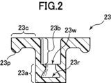
- FIG. 2 is a vertical cross-sectional view of a valve rubber of the valve rubber type solenoid valve of FIG. 1
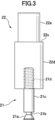
- FIG. 2 is a front view of a moving core and a retaining core of the rubber valve type solenoid valve of FIG. 1
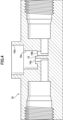
- FIG. 2 is a vertical cross-sectional view of a main body of the rubber valve type solenoid valve of FIG. 1
- FIG. 2 is a perspective view of a valve rubber seating surface of the valve rubber type solenoid valve of FIG. 1
- FIG. 2 is a schematic diagram of the rubber valve type solenoid valve of FIG. 1 in a valve closed state.
- FIG. 1 is a schematic vertical cross-sectional view of a rubber valve type solenoid valve according to an embodiment of the present invention
- FIG. 2 is a vertical cross-sectional view of a valve rubber of the valve rubber type solenoid valve of FIG. 1
- FIG. 2 is a schematic diagram of the rubber valve type solenoid valve of FIG. 1 in a maximum valve opening state
- FIG. 11 is a schematic vertical cross-sectional view of a rubber valve type solenoid valve according to another embodiment of the present invention.
- FIG. 9 is a schematic diagram of the rubber valve type solenoid valve of FIG. 8 in a valve closed state.
- FIG. 9 is a schematic diagram of the rubber valve type solenoid valve of FIG. 8 in a maximum valve opening state.
- FIG. 11 is a schematic vertical cross-sectional view of a rubber valve type solenoid valve according to still another embodiment of the present invention.
- 12 is a vertical cross-sectional view of a retaining core and a valve rubber of the valve rubber type solenoid valve of FIG. 11 .
- FIG. 12 is a schematic diagram of a baking process of the valve rubber of the valve rubber type solenoid valve of FIG. 11 .
- FIG. FIG. 1 is a schematic cross-sectional view of a conventional rubber valve type solenoid valve.
- FIG. 2 is a schematic vertical cross-sectional view of a first modified example of the rubber valve type solenoid valve of FIG. 1 .
- FIG. 3 is a vertical cross-sectional view of a modified example of the valve rubber of FIG. 2 .
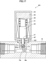
- 17 is a schematic vertical cross-sectional view of a second modified example of the rubber valve type solenoid valve of FIG. 1, which is equipped with the rubber valve of FIG. 16.
- FIG. 3 is a vertical cross-sectional view of another modified example of the valve rubber of FIG. 2 .
- 19 is a schematic vertical cross-sectional view of a third modified example of the rubber valve type solenoid valve of FIG. 1, which is equipped with the rubber valve of FIG. 18.
- FIG. 1 is a schematic longitudinal sectional view of a rubber valve type solenoid valve according to one embodiment of the present invention
- FIG. 2 is a longitudinal sectional view of a valve rubber of the rubber valve type solenoid valve of FIG. 1
- FIG. 3 is a front view of a moving core and a retaining core of the rubber valve type solenoid valve of FIG. 1
- FIG. 4 is a longitudinal sectional view of a main body of the rubber valve type solenoid valve of FIG. 1
- FIG. 5 is a perspective view of a valve rubber seating surface of the rubber valve type solenoid valve of FIG. 1.
- the rubber valve type solenoid valve 1 of this embodiment includes a main body 10 having a rubber valve seating surface 12 with one opening 10a, a rubber valve 23 arranged to seat on the rubber valve seating surface 12 of the main body 10, a retaining core 21 that holds the rubber valve 23 at one end (the lower end side of FIG. 1), and a moving core 22 connected to the other end side (the upper end side of FIG. 1) of the retaining core 21.
- the movable core 22 is movable in the axial direction relative to the fixed core 52 via a coil spring 51 (an example of a biasing member).
- the coil spring 51 exerts an elastic force (an example of a biasing force) on the moving core 22, biasing the moving core 22 and the retaining core 21 against the valve rubber seating surface 12 of the main body 10, and causes the opening and closing surface 23a of the valve rubber 23 to abut (seat) against the valve rubber seating surface 12 (the cylindrical portion 23b is stretched and deformed: see Figure 6).
- the rubber valve type solenoid valve 1 of this embodiment further includes an electromagnetic force application unit 40 (specifically, for example, an electromagnetic coil) that applies an electromagnetic force to the moving core 22, moving the moving core 22 and the retaining core 21 relative to the rubber valve seating surface 12 of the main body 10, thereby moving the rubber valve 23 relative to the rubber valve seating surface 12.
- an electromagnetic force application unit 40 specifically, for example, an electromagnetic coil
- the electromagnetic force application unit 40, the fixed core 52, and the upper end of the main body 10 are covered by a cover 53.
- the electromagnetic force application unit 40 of this embodiment applies an electromagnetic force to the moving core 22, moving the moving core 22 and the retaining core 21 in a direction away from the valve rubber seating surface 12 of the main body 10, thereby moving the valve rubber 23 away from the valve rubber seating surface 12 (the cylindrical portion 23b is shortened and deformed: see Figure 7).
- the moving core 22 of this embodiment is made of magnetic stainless steel material (K-M31).
- the present invention does not exclude a pattern in which the valve rubber 23 is subjected to an elastic force and separated from the valve rubber seating surface 12 before the electromagnetic force is applied to the moving core 22, and the valve rubber 23 abuts (seats) against the valve rubber seating surface 12 (the cylindrical portion 23b is stretched and deformed) when the electromagnetic force is applied to the moving core 22.
- the valve rubber 23 of this embodiment has an opening closing surface portion 23a, a cylindrical portion 23b extending from the opening closing surface portion 23a toward the retaining core 21, and a flange portion 23c extending annularly outward from the end of the cylindrical portion 23b on the retaining core 21 side.
- the valve rubber 23 of this embodiment is made of EPDM (ethylene propylene diene rubber) and has a hardness of, for example, A70 ⁇ 5.
- the retaining core 21 has a truncated cone-shaped portion 21a at the end on the opening closing surface portion 23a side.
- the retaining core 21 further has a small diameter cylindrical portion 21b (part of the small diameter constriction portion) adjacent to the truncated cone-shaped portion 21a, a large diameter cylindrical portion 21c (an example of a large diameter columnar portion) adjacent to the small diameter cylindrical portion 21b and extending toward the moving core 22, and a male thread portion 21d for screwing into the moving core 22.
- the male thread portion 21d for screwing can be replaced with any other known connecting element (for example, a mode in which the retaining core 21 and the moving core 22 are snap-fit connected can also be adopted).
- the retaining core 21 of this embodiment is made of stainless steel (magnetic properties are not required).
- the opening closing surface portion 23a of the valve rubber 23 covers the truncated cone-shaped portion 21a and the small diameter cylindrical portion 21b of the retaining core 21.
- the opening closing surface 23a of the valve rubber 23 is fixed with a vulcanizing adhesive to the end face (lower end face in FIG. 1) and circumferential surface of the truncated cone-shaped portion 21a and the circumferential surface of the small diameter cylindrical portion 21b.
- the valve rubber 23 is baked and molded integrally with the retaining core 21 (FIGS. 2 and 3 are shown separated for ease of explanation, but in reality the retaining core 21 and the moving core 22 are separable, and the retaining core 21 and the valve rubber 23 are molded integrally).
- no vulcanizing adhesive is applied to the underside of the large diameter cylindrical portion 21c (the other part of the small diameter constricted portion) adjacent to the circumferential surface of the small diameter cylindrical portion 21b.
- the vulcanizing adhesive applied to the circumferential surface of the small diameter cylindrical portion 21b is prevented from undesirably penetrating into the circumferential surface of the large diameter cylindrical portion 21c.
- the movable core 22 has a second cylindrical portion 22e on the fixed core 52 side, and a first cylindrical portion 22d that forms a step portion 22s between the second cylindrical portion 22e and the first cylindrical portion 22d.
- the second cylindrical portion 22e is 5 mm long and 3.9 mm in diameter
- the first cylindrical portion 22d is 8.1 mm long and 5.0 mm in diameter
- the large diameter cylindrical portion 21c is 4.1 mm long and 1.8 mm in diameter
- the small diameter cylindrical portion 21b is 0.4 mm long and 1.0 mm in diameter
- the truncated cone-shaped portion 21a is 0.9 mm long, has a maximum diameter of 1.8 mm, and has an apex angle of approximately 60°.
- the coil spring 51 has a natural length of 7.7 mm and is inserted in a compressed state between the step portion 22s and the fixed core 52 (in the opening closed state (see FIG. 6), the coil spring length is 5.3 mm).
- the spring constant of the coil spring 51 is 0.9 N/mm.
- the outer shape of the opening closing surface portion 23a of the valve rubber 23 is a cylindrical portion with a diameter of 3 mm and a height of 1.8 mm, and at the upper center is provided a truncated cone recess 23r into which the truncated cone shaped portion 21a of the retaining core 21 fits, and a small diameter cylindrical portion 23w into which the small diameter cylindrical portion 21b of the retaining core 21 fits.
- the truncated cone recess 23r has an apex angle of approximately 60°, a bottom diameter (maximum diameter) of 1.8 mm (marked R0.1), and an upper end portion with R0.2.
- the upper side of this R0.2 region is continuous with the small diameter cylindrical portion 23w, and the height of the open closing surface portion 23a to the upper surface of the small diameter cylindrical portion 23w is 1.8 mm, the height of the open closing surface portion 23a to the lower surface of the small diameter cylindrical portion 23w is 1.4 mm, and the depth of the truncated cone recess 23r to the lower surface of the small diameter cylindrical portion 23w is 0.9 mm.
- the tubular portion 23b of the valve rubber 23 is a cylindrical portion with an inner diameter of 2.0 mm, an outer diameter of 3.0 mm, and a length of 2.7 mm, and extends from the upper surface of the opening closing surface portion 23a toward the retaining core 21.
- the flange portion 23c of the valve rubber 23 extends outward in an annular shape from the end of the cylindrical portion 23b on the retaining core 21 side.
- the flange portion 23c of this embodiment has an outer diameter of 8.0 mm and a uniform thickness of 1.0 mm. That is, the flange portion 23c of this embodiment does not have a thin-walled portion.
- the lower surface of the outer peripheral region of the flange portion 23c is provided with an annular protrusion 23p with a semicircular cross section of R0.5 for fixing to the main body 10.
- the outer surface of the cylindrical portion 23b and the lower surface of the flange portion 23c are smoothly continuous (with a radius) (for example, R0.5).
- the lower surface of the flange portion 23c and the protrusion 23p are also smoothly continuous (with a radius) (for example, R0.3).
- the main body 10 of this embodiment has a large diameter hole 10d in which the flange portion 23c of the valve rubber 23 is placed.
- the large diameter hole 10d is a cylindrical hole with a diameter of 8.1 mm and a height of 3.2 mm.
- the flange portion 23c placed in the large diameter hole 10d is fixed to the main body 10 in a compressed state from above via an annular pressing part (also called an adapter) 42 having the same outer diameter (8 mm) as the flange portion 23c and an electromagnetic force application part 40.
- an annular pressing part also called an adapter
- the height of the outer region (region outside the diameter 6 mm) of the annular pressing part 42 is 2.0 mm
- the annular protrusion 23p of the flange portion 23c is fixed in a compressed state of 0.3 mm.
- the inner region (region inside the diameter 6 mm) of the pressing part 42 in this embodiment has a height of 1.4 mm and an inner diameter of 4 mm, which is slightly smaller than the outer diameter (5 mm) of the first cylindrical part 22d of the moving core 22, and functions as a stopper that defines the downward movement limit of the moving core 22.
- the inner surface and the upper surface of the annular pressing part 42 are smoothly continuous (with a radius) (e.g., R 0.2), and similarly, it is preferable that the inner surface and the lower surface of the annular pressing part 42 are smoothly continuous (with a radius) (e.g., R 0.2). It is also possible to configure the entire annular pressing part 42 with a flat height without providing a difference in height between the outer region and the inner region of the annular pressing part 42.
- a small diameter hole 10c is provided coaxially below the large diameter hole 10d.
- the small diameter hole 10c is a cylindrical hole with a diameter of 5.0 mm and a height of 3.8 mm.
- the cylindrical portion 23b and the opening closing surface portion 23a are inserted into the small diameter hole 10c.
- one feature of this embodiment is that when neither electromagnetic force nor elastic force is acting, i.e., when the valve rubber 23 is in an unloaded state, the opening closing surface portion 23a (its bottom surface) is located at a height half the maximum opening height from the valve rubber seating surface 12.
- This feature is an essential feature of the second aspect of the present invention. However, it is optional (not essential) for the first aspect of the present invention.
- the area of the main body 10 on the valve rubber seating surface 12 side is formed as a cylindrically raised area from the bottom surface of the small diameter hole 10c.
- the cylindrically raised area has an outer diameter of 2.0 mm and a height of 0.5 mm.
- the valve rubber seating surface 12 has an opening 10a (diameter 0.8 mm) that is coaxial with the large diameter hole 10d and the small diameter hole 10c. And, another opening 10b (diameter 1.2 mm) is provided at the bottom of the small diameter hole 10c, away from the cylindrically raised area (which provides the valve rubber seating surface 12) (see Figure 5).
- the flow paths leading to the openings 10a, 10b each extend downward into the main body 10, and then extend away from each other symmetrically.
- the diameter of the portion of each flow path that extends laterally is, for example, about 2.0 mm, and the flow path depth to the axis of that portion is, for example, about 2.0 mm based on the bottom surface of the small diameter hole 10c, and that portion is connected to a screw hole for connecting piping.
- the main body 10 of this embodiment including the valve rubber seating surface 12, is formed by injection molding from PPS resin.
- PBT resin may be used instead of PPS resin.
- the area providing the valve rubber seating surface 12 and the area below it may be configured as separate entities, and may be made of different materials.
- the electromagnetic force application unit 40 applies an electromagnetic force to the moving core 22. This causes the moving core 22 to move in a direction away from the valve rubber seating surface 12 of the main body 10, and the valve rubber 23 is moved in a direction away from the valve rubber seating surface 12. As a result, as shown in FIG. 7, the cylindrical portion 23b of the valve rubber 23 is contracted, and a partial area of the flange portion 23c located on the inside of the pressing part 42 is very slightly deformed into a diaphragm valve, causing the valve rubber 23 to move away from the valve rubber seating surface 12 and opening the opening 10a.
- the closing stroke of the cylindrical portion 23b from the unloaded state of the cylindrical portion 23b to the state where the cylindrical portion 23b is in an extended state, the valve rubber 23 is seated on the valve rubber seating surface 12, and the opening closing surface portion 23a closes the opening 10a is approximately 0.15 mm.
- the opening stroke of the cylindrical portion 23b from the unloaded state of the cylindrical portion 23b to the state in which the cylindrical portion 23b is contracted, the valve rubber 23 is further separated from the valve rubber seating surface 12, and the opening closing surface portion 23a further opens the opening 10a is approximately 0.15 mm.
- the ratio of the closing stroke of the cylindrical portion 23b to the opening stroke of the cylindrical portion 23b is approximately 1:1.
- the flange portion 23c of this embodiment does not have a so-called thin-walled portion, and has a thickness of 1.0 mm or more at any position. This makes it possible to achieve extremely high durability.
- the opening closing surface 23a of the valve rubber 23 and the retaining core 21 are fixed with a vulcanizing adhesive, so that the fixation between the two is stronger. That is, according to this embodiment, the moving core 22 that receives the electromagnetic force and the retaining core 21 that holds the valve rubber 23 are separate bodies that are connected together, so that the valve rubber 23 can be baked and molded integrally with the retaining core 21. For example, it is possible to prepare a corresponding mold and bake and mold the valve rubber 23 around a specified portion of the retaining core 21, and therefore, during this baking and molding, the opening closing surface 23a of the valve rubber 23 and the retaining core 21 can be fixed with a vulcanizing adhesive.
- the retaining core 21 has a truncated cone-shaped portion 21a and a small diameter cylindrical portion 21b (part of the small diameter constriction portion) at the end on the opening closing surface portion 23a side, and the opening closing surface portion 23a of the valve rubber 23 has a truncated cone recess 23r and a small diameter cylindrical portion 23w that cover the truncated cone-shaped portion 21a and small diameter cylindrical portion 21b of the retaining core 21.
- the engagement relationship brought about by these shapes also effectively prevents undesired detachment between the retaining core 21 and the opening closing surface portion 23a of the valve rubber 23.
- the electromagnetic force application unit 40 applies an electromagnetic force to the moving core 22, moving the moving core 22 and the retaining core 21 in a direction away from the valve rubber seating surface 12 of the main body 10, thereby moving the valve rubber 23 in a direction away from the valve rubber seating surface 12.
- the coil spring 51 applies an elastic force to the moving core 22, moving the moving core 22 and the retaining core 21 in a direction approaching the valve rubber seating surface 12 of the main body 10, thereby moving the valve rubber 23 in a direction approaching the valve rubber seating surface 12.
- the tubular portion 23b of the valve rubber 23 When only elastic force is acting (when electromagnetic force is not acting), the tubular portion 23b of the valve rubber 23 is in an expanded state (and a portion of the flange portion 23c located on the inside of the pressing part 42 is very slightly deformed as a diaphragm valve), so that the valve rubber 23 is seated on the valve rubber seating surface 12 and the opening closing surface portion 23a closes the opening 10a, and when electromagnetic force is acting (elastic force is also acting, but the electromagnetic force exceeds the elastic force), the tubular portion 23b of the valve rubber 23 is in a contracted state (and a portion of the flange portion 23c located on the inside of the pressing part 42 is very slightly deformed as a diaphragm valve), so that the valve rubber 23 moves further away from the valve rubber seating surface 12 and the opening closing surface portion 23a further opens the opening 10a.
- the unloaded state (natural state) of the cylindrical portion 23b does not correspond to either the state in which the opening closing surface portion 23a closes the opening 10a, or the state in which the opening closing surface portion 23a is furthest from the opening 10a, but corresponds to an intermediate state between the two. Therefore, although the deformation of the cylindrical portion 23b includes both elongation deformation and contraction deformation, the maximum value of each of these deformations is kept smaller than when only elongation deformation occurs (the natural state corresponds to the maximum open state) or when only contraction deformation occurs (the natural state corresponds to the closed state). This suppresses the occurrence of distortion due to deformation, further improving the durability of the valve rubber 23.
- the closing stroke of the cylindrical portion 23b and the opening stroke of the cylindrical portion 23b are 1:1, but the effects of the present invention can be expected if they are within the range of 2:1 to 1:2 (preferably within the range of 3:2 to 2:3).
- the rubber valve type solenoid valve 1 of this embodiment is designed to maintain the open and closed state by the elastic force of the coil spring 51. Therefore, no power consumption is required in the open and closed state. As a result, a high energy saving effect can be obtained.
- the inventors confirmed that when ink from a commercial printer is used as the fluid in the rubber valve type solenoid valve 1 of this embodiment and the pressure range applied to the IN side flow path is set to -70 to 420 kPa, the ink flow/blockage can be smoothly controlled and the control performance can be made to last longer.
- valve rubber seating surface 12 only one opening 10a is provided on the valve rubber seating surface 12, and another opening 10b is provided on the bottom surface of the small diameter hole 10c, but this is not limited to this embodiment, and a type in which two openings are provided on the valve rubber seating surface 12 may also be used.
- a coil spring 51 which is an elastic member, is used as the biasing means, but instead, a mechanism or configuration that applies air pressure or liquid pressure to the moving core 22 may be used.
- vulcanized adhesive is applied to the end face and peripheral surface of the truncated cone-shaped portion 21a and the peripheral surface of the small diameter cylindrical portion 21b, but an embodiment in which vulcanized adhesive is applied only to the end face and peripheral surface of the truncated cone-shaped portion 21a and no vulcanized adhesive is applied to the peripheral surface of the small diameter cylindrical portion 21b is also within the scope of the present invention, at least at the time of filing this application.
- vulcanizing adhesive is provided only on the end face and circumferential surface of the truncated cone-shaped portion 21a and the lower region of the circumferential surface of the small diameter cylindrical portion 21b, and no vulcanizing adhesive is provided in the upper region of the circumferential surface of the small diameter cylindrical portion 21b, is also within the scope of the present invention, at least at the time of filing this application.
- an embodiment in which a vulcanizing adhesive is provided on the end face and circumferential surface of the truncated cone-shaped portion 21a, the circumferential surface of the small diameter cylindrical portion 21b, and the inner peripheral region of the underside of the large diameter cylindrical portion 21c (the other part of the small diameter constricted portion) (no vulcanizing adhesive is provided on the outer peripheral region of the underside of the large diameter cylindrical portion 21c) is also within the scope of the present invention.
- the unloaded state (natural state) of the valve rubber does not correspond to either the state in which the opening is closed or the state in which it is furthest from the opening, but corresponds to a state intermediate between the two, is also effective in other types of solenoid valves different from the embodiments described above.
- this feature is optional (not essential) for the first aspect of the present invention. That is, a modification of this embodiment in which the no-load state (natural state) of the valve rubber corresponds to the state where the opening is closed also has a sufficiently advantageous effect, and a modification of this embodiment in which the no-load state (natural state) of the valve rubber corresponds to the state where it is furthest from the opening also has a sufficiently advantageous effect.
- FIG. 8 is a schematic vertical cross-sectional view of a rubber valve type solenoid valve according to another embodiment of the present invention
- FIG. 9 is a schematic view of the rubber valve type solenoid valve in a valve closed state
- FIG. 10 is a schematic view of the rubber valve type solenoid valve in a valve maximum open state.
- the valve rubber type solenoid valve 201 of this embodiment comprises a main body 210 having a valve rubber seating surface 212 with one opening 210a, a valve rubber 223 arranged to seat on the valve rubber seating surface 212 of the main body 210, a retaining core 221 that holds the valve rubber 223 at one end side (the lower end side in Figure 8), and a moving core 222 connected to the other end side (the upper end side in Figure 8) of the retaining core 221.
- the shape of the rubber valve 223 in the rubber valve type solenoid valve 201 of this embodiment is the shape of a conventionally known diaphragm valve (see Figure 14).
- the movable core 222 is arranged to be movable in the axial direction relative to the fixed core 252 via a coil spring 251 (an example of a biasing member).
- the coil spring 251 exerts an elastic force (an example of a biasing force) on the movable core 222, biasing the movable core 222 and the retaining core 221 against the valve rubber seating surface 212 of the main body 210, and causing the valve rubber 223 to abut (seat) against the valve rubber seating surface 212 (see Figure 9).
- the rubber valve type solenoid valve 201 of this embodiment further includes an electromagnetic force application unit 240 (specifically, for example, an electromagnetic coil) that applies an electromagnetic force to the moving core 222, moving the moving core 222 and the retaining core 221 relative to the valve rubber seating surface 212 of the main body 210, thereby moving the valve rubber 223 relative to the valve rubber seating surface 212.
- an electromagnetic force application unit 240 specifically, for example, an electromagnetic coil
- the electromagnetic force application unit 240, the fixed core 252, and the upper end of the main body 210 are covered by a cover 253.
- the electromagnetic force application unit 240 of this embodiment applies an electromagnetic force to the moving core 222, moving the moving core 222 and the retaining core 221 in a direction away from the valve rubber seating surface 212 of the main body 210, thereby moving the valve rubber 223 away from the valve rubber seating surface 12 (see FIG. 10).
- the moving core 222 of this embodiment is also made of magnetic stainless steel material (K-M31).
- the present invention does not exclude a pattern in which the valve rubber 223 is separated from the valve rubber seating surface 212 by an elastic force before an electromagnetic force is applied to the moving core 222, and the valve rubber 223 abuts (seats) against the valve rubber seating surface 212 when an electromagnetic force is applied to the moving core 222.
- the valve rubber 223 in this embodiment is made of EPDM (ethylene propylene diene rubber) and has a hardness of, for example, A70 ⁇ 5.
- the retaining core 221 has a truncated cone-shaped portion at the end on the opening closing surface side. Furthermore, the retaining core 221 has a cylindrical portion adjacent to the truncated cone-shaped portion, and a male thread portion (not shown) for screwing into the moving core 221.
- the male thread portion for screwing can be replaced with any other known connecting element (for example, a mode in which the retaining core 221 and the moving core 222 are connected by a snap fit can also be adopted).
- the retaining core 221 of this embodiment is also made of stainless steel (magnetic properties are not required).
- the opening closing surface of the valve rubber 223 covers the truncated cone-shaped portion and the cylindrical portion of the retaining core 221.
- valve rubber 223 The opening and closing surface of the valve rubber 223 is fixed to the end face (the lower end face in FIG. 8) and the circumferential surface of the truncated cone-shaped portion with a vulcanizing adhesive. In other words, the valve rubber 223 is baked and molded integrally with the retaining core 221.
- the coil spring 251 has a natural length of 7.7 mm and is inserted in a compressed state between the step portion and the fixed core 252 (in the open closed state (see FIG. 9), the coil spring length is 5.3 mm).
- the spring constant of the coil spring 251 is 0.9 N/mm.
- the main body 210 of this embodiment has a large diameter hole in which the flange portion of the valve rubber 223 is placed.
- the flange portion of the valve rubber 223 placed in the large diameter hole is fixed to the main body portion 210 in a compressed state from above via an annular pressing part (also called an adapter) 242 and an electromagnetic force acting part 240.
- annular pressing part also called an adapter
- a small diameter hole is provided coaxially below the large diameter hole, and the area of the main body 210 on the valve rubber seating surface 212 side is formed as a cylindrical protrusion from the bottom surface of the small diameter hole.
- a feature of this embodiment is that when neither electromagnetic force nor elastic force is acting, i.e., when the valve rubber 223 is in an unloaded state, the (bottom surface of) the opening and closing surface portion of the valve rubber 223 is located at a height half the maximum opening height from the valve rubber seating surface 212 (see FIG. 8).
- This feature is an essential feature of the second aspect of the present invention.
- the rest of the configuration of the rubber valve type solenoid valve 201 of this embodiment is substantially the same as that of the rubber valve type solenoid valve 1 described with reference to Figures 1 to 7.
- the electromagnetic force application unit 240 applies an electromagnetic force to the moving core 222.
- This causes the moving core 222 and the retaining core 221 to move in a direction away from the valve rubber seating surface 212 of the main body 210, and accordingly the valve rubber 223 moves in a direction away from the valve rubber seating surface 212.
- the valve rubber 223 becomes elastically deformed in the opposite direction, and the valve rubber 223 moves away from the valve rubber seating surface 212, opening the opening 210a.
- the closing stroke of the valve rubber 223 from the no-load state to the state in which the valve rubber 223 is in an elastically deformed state and the valve rubber 223 is seated on the valve rubber seating surface 212 and the opening closing surface portion closes the opening 210a is approximately 0.15 mm.
- the opening stroke of the valve rubber 223 from the no-load state to the state in which the valve rubber 223 elastically deforms in the opposite direction and moves further away from the valve rubber seating surface 212 so that the opening closing surface portion further opens the opening 210a is approximately 0.15 mm.
- the ratio of the closing stroke of the valve rubber 223 to the opening stroke of the valve rubber 223 is approximately 1:1.
- the electromagnetic force application unit 240 applies an electromagnetic force to the moving core 222, moving the moving core 222 and the retaining core 221 in a direction away from the valve rubber seating surface 212 of the main body portion 210, thereby moving the valve rubber 223 in a direction away from the valve rubber seating surface 212.
- the coil spring 251 applies an elastic force to the moving core 222, moving the moving core 222 and the retaining core 221 in a direction approaching the valve rubber seating surface 212 of the main body portion 210, thereby moving the valve rubber 223 in a direction approaching the valve rubber seating surface 212.
- valve rubber 223 When only elastic force is acting (when electromagnetic force is not acting), the valve rubber 223 is in an elastically deformed state, and the valve rubber 223 sits on the valve rubber seating surface 212 so that the opening closing surface closes the opening 210a.
- electromagnetic force an elastic force is also acting, but the electromagnetic force exceeds the elastic force
- the valve rubber 223 is in an elastically deformed state in the opposite direction, and the valve rubber 223 moves further away from the valve rubber seating surface 212 so that the opening closing surface further opens the opening 210a.
- the no-load state (natural state) of the rubber valve 223 does not correspond to either the state in which the opening closing surface closes the opening 210a, or the state in which the opening closing surface is furthest from the opening 210a, but corresponds to an intermediate state between the two. Therefore, although the elastic deformation of the rubber valve 223 includes both downward elastic deformation and upward elastic deformation, the maximum value of each of these deformations is kept smaller than when only downward elastic deformation occurs (the natural state corresponds to the maximum open state) or when only upward elastic deformation occurs (the natural state corresponds to the closed state). This suppresses the occurrence of distortion due to deformation, improving the durability of the rubber valve 223.
- the closing stroke of the valve rubber 223 and the opening stroke of the valve rubber 223 are 1:1, but the effects of the present invention can be expected if they are within the range of 2:1 to 1:2 (preferably within the range of 3:2 to 2:3).
- FIG. 11 is a schematic longitudinal cross-sectional view of a rubber valve type solenoid valve according to yet another embodiment of the present invention
- FIG. 12 is a longitudinal cross-sectional view of a retaining core and valve rubber of the rubber valve type solenoid valve
- FIG. 13 is a schematic view of the baking process of the valve rubber of the rubber valve type solenoid valve.
- the valve rubber type solenoid valve 301 of this embodiment comprises a main body 310 having a valve rubber seating surface 312 with one opening 310a, a valve rubber 323 arranged to seat on the valve rubber seating surface 312 of the main body 310, a retaining core 321 that holds the valve rubber 323 at one end side (the lower end side in Figure 11), and a moving core 322 connected to the other end side of the retaining core 321 (the upper end side in Figure 11).
- the movable core 322 is movable in the axial direction relative to the fixed core 352 via a coil spring 351 (an example of a biasing member).
- the coil spring 351 exerts an elastic force (an example of a biasing force) on the movable core 322, biasing the movable core 322 and the retaining core 321 against the valve rubber seating surface 312 of the main body 310, and causes the opening and closing surface portion 323a of the valve rubber 323 to abut (seat) against the valve rubber seating surface 312 (the cylindrical portion 323b is stretched and deformed: see Figure 12).
- the rubber valve type solenoid valve 301 of this embodiment further includes an electromagnetic force application unit 340 (specifically, an electromagnetic coil, for example) that applies an electromagnetic force to the moving core 322, moving the moving core 322 and the retaining core 321 relative to the rubber valve seating surface 312 of the main body 310, thereby moving the rubber valve 323 relative to the rubber valve seating surface 312.
- an electromagnetic force application unit 340 specifically, an electromagnetic coil, for example
- the electromagnetic force application unit 340, the fixed core 352, and the upper end of the main body 310 are covered by a cover 353.
- the electromagnetic force application section 340 of this embodiment applies an electromagnetic force to the moving core 322, moving the moving core 322 and the retaining core 321 in a direction away from the valve rubber seating surface 312 of the main body section 310, thereby moving the valve rubber 323 away from the valve rubber seating surface 312 (the cylindrical section 323b is shortened and deformed: see FIG. 12).
- the moving core 322 of this embodiment is also made of magnetic stainless steel material (K-M31).
- the present invention does not exclude a pattern in which the valve rubber 323 is separated from the valve rubber seating surface 312 by an elastic force before an electromagnetic force is applied to the moving core 322, and the valve rubber 323 abuts (seats) against the valve rubber seating surface 312 (the cylindrical portion 323b is stretched and deformed) by applying an electromagnetic force to the moving core 322.
- the valve rubber 323 of this embodiment has an opening closing surface portion 323a, a cylindrical portion 323b extending from the opening closing surface portion 323a toward the retaining core 321, and a flange portion 323c extending in an annular shape outward from the end of the cylindrical portion 323b on the retaining core 321 side.
- the valve rubber 323 of this embodiment is made of EPDM (ethylene propylene diene rubber) and has a hardness of, for example, A70 ⁇ 5.
- the retaining core 321 has a large-diameter tip 321a at the end on the opening closing surface 323a side.
- the retaining core 321 further has a small-diameter constricted portion 321b (the longitudinal section of the inner circumferential surface is substantially arc-shaped: see FIG. 12) adjacent to the large-diameter tip 321a, a large-diameter cylindrical portion 321c (an example of a large-diameter columnar portion) adjacent to the small-diameter constricted portion 321b and extending toward the moving core 322, and a male screw portion 321d for screwing into the moving core 322.
- the male screw portion 321d for screwing can be replaced with any other known connecting element (for example, a mode in which the retaining core 321 and the moving core 322 are snap-fitted can also be adopted).
- the retaining core 321 of this embodiment is made of stainless steel (magnetic properties are not required).
- the opening closing surface portion 323a of the valve rubber 323 covers the large diameter tip portion 321a and the small diameter constriction portion 321b of the retaining core 321.
- the opening and closing surface portion 323a of the valve rubber 323 is fixed with a vulcanizing adhesive to the end face (lower end surface in FIG. 12) and circumferential surface of the large-diameter tip portion 321a, and to the large-diameter tip portion side surface (annular region) and inner circumferential surface (annular region with a substantially arc-shaped longitudinal section) of the small-diameter constriction portion 321b.
- the valve rubber 323 is baked and molded integrally with the retaining core 321.
- the baking molding process of the valve rubber 323 is carried out using an upper mold and a lower mold as shown in FIG. 13, for example.
- the size of the hole in the lower mold into which the male threaded portion 321d is fitted smaller than the diameter of the large diameter cylindrical portion 321c, the shape of the molded valve rubber 323 and the shape of the mold itself can be simplified.
- no vulcanizing adhesive is applied to the underside of the large diameter cylindrical section 321c (the side surface of the large diameter cylindrical section of the small diameter constriction 321b) adjacent to the inner circumferential surface of the small diameter constriction 321b.
- the vulcanizing adhesive applied to the inner circumferential surface of the small diameter constriction 321b is prevented from undesirably penetrating the circumferential surface of the large diameter cylindrical section 321c.
- the movable core 322 has a second cylindrical portion on the fixed core 352 side and a first cylindrical portion that forms a step portion between the second cylindrical portion and the first cylindrical portion.
- the second cylindrical portion is 6.5 mm long and 5.0 mm in diameter
- the first cylindrical portion is 11.0 mm long and 6.5 mm in diameter
- the large diameter columnar portion 321c is 5.4 mm long and 2.4 mm in diameter
- the small diameter constricted portion 321b is 0.6 mm long and has a minimum diameter of 1.5 mm
- the large diameter tip portion 321a is 0.5 mm long and has a maximum diameter of 2.4 mm.
- the coil spring 351 has a natural length of 8.8 mm and is inserted in a compressed state between the step portion and the fixed core 352 (in the opening closed state, the coil spring length is 8.0 mm).
- the spring constant of the coil spring 51 is 0.9 N/mm.
- the outer shape of the opening closing surface 323a of the valve rubber 323 is a cylindrical portion with a diameter of 3.4 mm and a height of 2.1 mm, and in the upper center portion is provided a large diameter tip recess 323r into which the large diameter tip portion 321a of the retaining core 21 fits, and a small diameter narrowed portion 323w into which the small diameter constricted portion 321b of the retaining core 21 fits.
- the large diameter tip recess 323r has a bottom diameter (maximum diameter) of 2.4 mm and a depth of 0.5 mm.
- the tubular portion 323b of the valve rubber 323 is a cylindrical portion with an inner diameter of 2.4 mm, an outer diameter of 3.4 mm, and a length of 5.4 mm, and extends from the upper surface of the opening closing surface portion 323a toward the retaining core 321.
- the flange portion 323c of the valve rubber 323 extends outward in an annular shape from the end of the cylindrical portion 323b on the retaining core 321 side.
- the flange portion 323c of this embodiment has an outer diameter of 8.0 mm and a uniform thickness of 0.5 mm. In other words, the flange portion 323c of this embodiment does not have a thin-walled portion.
- the lower surface of the outer peripheral region of the flange portion 323c is provided with an annular protrusion 323p with a semicircular cross section and R0.4 for fixing to the main body portion 310.
- the lower surface of the flange portion 323c and the protrusion 323p are smoothly continuous (with a radius) (for example, R0.3).
- the main body 310 of this embodiment has a large diameter hole in which the flange portion of the valve rubber 323 is placed.
- the flange portion of the valve rubber 323 placed in the large diameter hole is fixed to the main body 310 in a compressed state from above via an annular pressing part (also called an adapter) 342 having the same outer diameter (8 mm) as the flange portion 323c and an electromagnetic force application part 340.
- an annular pressing part also called an adapter
- the height of the outer side area (area outside the diameter 6 mm) of the annular pressing part 342 is 2.0 mm
- the annular protrusion 323p of the flange portion 323c is fixed in a compressed state of 0.3 mm.
- the inner side area (area inside the diameter 6 mm) of the pressing part 342 in this embodiment has a height of 1.4 mm, and its inner diameter is slightly smaller than the outer diameter of the moving core 322, so that it functions as a stopper that defines the downward movement limit of the moving core 322.
- the inner surface and the upper surface of the annular pressing part 342 are smoothly continuous (radiused) (e.g., R0.2), and similarly, it is preferable that the inner surface and the lower surface of the annular pressing part 342 are smoothly continuous (radiused) (e.g., R0.2). It is also possible to configure the entire annular pressing part 342 with a flat height without providing a difference in height between the outer region and the inner region of the annular pressing part 342.
- a small diameter hole is provided coaxially below the large diameter hole, and the area of the main body 310 on the valve rubber seating surface 312 side is formed as a cylindrical protrusion from the bottom surface of the small diameter hole.
- one feature of this embodiment is that when neither electromagnetic force nor elastic force is acting, i.e., when the valve rubber 323 is in an unloaded state, the (bottom surface of) the opening closing surface portion of the valve rubber 323 is located at a height half the maximum opening height from the valve rubber seating surface 312 (see FIG. 11).
- This feature is an essential feature of the second aspect of the present invention. However, it is optional (not essential) for the first aspect of the present invention.
- the rest of the configuration of the rubber valve type solenoid valve 301 of this embodiment is substantially the same as that of the rubber valve type solenoid valve 1 described with reference to Figures 1 to 7.
- the electromagnetic force application section 340 applies an electromagnetic force to the moving core 322.
- the moving core 322 and the retaining core 321 are moved in a direction away from the valve rubber seating surface 312 of the main body section 310, and the valve rubber 323 is moved in a direction away from the valve rubber seating surface 312.
- the cylindrical section 323b of the valve rubber 323 is contracted, and a partial area of the flange section 23c located inside the pressing part 342 is very slightly deformed into a diaphragm valve, causing the valve rubber 323 to move away from the valve rubber seating surface 312 and opening the opening 310a.
- the closing stroke of the cylindrical portion 323b from the unloaded state to the state in which the cylindrical portion 323b is in an extended state, the valve rubber 323 is seated on the valve rubber seating surface 312, and the opening closing surface portion 323a closes the opening 310a is approximately 0.15 mm.
- the opening stroke of the cylindrical portion 323b from the unloaded state to the state in which the cylindrical portion 323b is contracted, the valve rubber 323 is further separated from the valve rubber seating surface 312, and the opening closing surface portion 323a further opens the opening 310a is approximately 0.15 mm.
- the ratio of the closing stroke of the cylindrical portion 323b to the opening stroke of the cylindrical portion 323b is approximately 1:1.
- the flange portion 323c of this embodiment does not have a so-called thin-walled portion, and has a thickness of 0.5 mm or more at any position. This makes it possible to achieve extremely high durability.
- the opening closing surface 323a of the valve rubber 323 and the retaining core 321 are fixed with a vulcanizing adhesive, so that the fixation between the two is stronger. That is, according to this embodiment, the moving core 322 that receives the electromagnetic force and the retaining core 321 that holds the valve rubber 323 are separate bodies that are connected together, so that the valve rubber 323 can be baked and molded integrally with the retaining core 321. For example, it is possible to prepare a corresponding mold and bake and mold the valve rubber 323 around a specified portion of the retaining core 321. Therefore, during the baking process, the opening closing surface 323a of the valve rubber 323 can be fixed to the retaining core 321 with a vulcanizing adhesive.
- the retaining core 321 has a large diameter tip portion 321a and a small diameter constricted portion 321b at the end on the opening closing surface portion 323a side
- the opening closing surface portion 323a of the valve rubber 323 has a large diameter tip recess 323r and a small diameter constricted portion 323w that cover the large diameter tip portion 321a and small diameter constricted portion 321b of the retaining core 321.
- the engagement relationship brought about by these shapes also effectively prevents undesired detachment between the retaining core 321 and the opening closing surface portion 323a of the valve rubber 323.
- the electromagnetic force application unit 340 applies an electromagnetic force to the moving core 322, moving the moving core 322 and the retaining core 321 in a direction away from the valve rubber seating surface 312 of the main body 310, thereby moving the valve rubber 323 in a direction away from the valve rubber seating surface 312.
- the coil spring 351 applies an elastic force to the moving core 322, moving the moving core 322 and the retaining core 321 in a direction approaching the valve rubber seating surface 312 of the main body 310, thereby moving the valve rubber 323 in a direction approaching the valve rubber seating surface 312.
- the tubular portion 323b of the valve rubber 323 When only elastic force is acting (when electromagnetic force is not acting), the tubular portion 323b of the valve rubber 323 is in an extended state (and a portion of the flange portion 23c located inside the pressing part 342 is very slightly deformed as a diaphragm valve), so that the valve rubber 323 is seated on the valve rubber seating surface 312 and the opening closing surface closes the opening 310a, and when electromagnetic force is acting (elastic force is also acting, but the electromagnetic force exceeds the elastic force), the tubular portion 323b of the valve rubber 323 is in a shortened state (and a portion of the flange portion 23c located inside the pressing part 342 is very slightly deformed as a diaphragm valve), so that the valve rubber 323 is further separated from the valve rubber seating surface 312 and the opening closing surface further opens the opening 310a.
- the unloaded state (natural state) of the cylindrical portion 323b does not correspond to either the state in which the opening closing surface closes the opening 310a, or the state in which the opening closing surface is furthest from the opening 310a, but corresponds to an intermediate state between the two. Therefore, although the elastic deformation of the cylindrical portion 323b includes both elongation deformation and contraction deformation, the maximum deformation value of each of these is kept smaller than when only elongation deformation occurs (the natural state corresponds to the maximum open state) or when only contraction deformation occurs (the natural state corresponds to the closed state). This suppresses the occurrence of distortion due to deformation, further improving the durability of the valve rubber 323.
- the closing stroke of the valve rubber 323 and the opening stroke of the valve rubber 323 are 1:1, but the effects of the present invention can be expected if the ratio is within the range of 2:1 to 1:2 (preferably within the range of 3:2 to 2:3).
- this feature is optional (not essential) for the first aspect of the present invention. That is, a modification of this embodiment in which the no-load state (natural state) of the valve rubber corresponds to the state where the opening is closed also has a sufficiently advantageous effect, and a modification of this embodiment in which the no-load state (natural state) of the valve rubber corresponds to the state where it is furthest from the opening also has a sufficiently advantageous effect.
- the rubber valve type solenoid valve 301 of this embodiment is designed to maintain the open and closed state by the elastic force of the coil spring 351. Therefore, no power consumption is required in the open and closed state. As a result, a high energy saving effect can be obtained.
- the inventors confirmed that when ink from a commercial printer is applied as the fluid to the rubber valve type solenoid valve 301 of this embodiment and the pressure range applied to the IN side flow path is set to -70 to 420 kPa, the ink flow/blockage can be smoothly controlled and the control performance can be made to have a long life.
- valve rubber seating surface 312 only one opening 310a is provided on the valve rubber seating surface 312, and another opening 310b is provided on the bottom surface of the small diameter hole 310c, but this is not limited to this embodiment, and a type in which two openings are provided on the valve rubber seating surface 312 may also be used.
- the coil spring 351 which is an elastic member, is used as the biasing means, but instead, a mechanism or configuration that applies air pressure or liquid pressure to the moving core 322 may be used.
- vulcanized adhesive is applied to the end face and circumferential surface of the large diameter tip portion 321a and the large diameter tip side surface and inner peripheral surface of the small diameter constriction portion 321b.
- vulcanized adhesive is applied only to the end face and circumferential surface of the large diameter tip portion 321a and the large diameter tip side surface of the small diameter constriction portion 321b, and no vulcanized adhesive is applied to the inner peripheral surface of the small diameter constriction portion 321b, is also within the scope of the present invention, at least at the time of filing this application.
- vulcanizing adhesive is provided only on the end face and circumferential surface of the large diameter tip portion 321a and the side surface of the large diameter tip portion and the lower region of the inner circumferential surface of the small diameter constriction portion 321b, and no vulcanizing adhesive is provided on the upper region of the inner circumferential surface of the small diameter constriction portion 321b, is also within the scope of the present invention.
- vulcanizing adhesive is provided on the end face and circumferential surface of the large diameter tip portion 321a, the large diameter tip side surface and inner circumferential surface of the small diameter constricted portion 321b, and the inner peripheral region of the underside of the large diameter cylindrical portion 21c (another part of the small diameter constricted portion 321b) (no vulcanizing adhesive is provided on the outer peripheral region of the underside of the large diameter cylindrical portion 21c) is also within the scope of the present invention.
- the vulcanizing adhesive it is preferable to have an area between the large diameter tip portion 321a where the vulcanizing adhesive is not applied so that the vulcanizing adhesive applied to the large diameter tip portion 321a does not undesirably penetrate onto the peripheral surface of the large diameter cylindrical portion 321c.
- Fig. 15 is a schematic vertical cross-sectional view of a rubber valve type solenoid valve 1' which is a first modified example of the rubber valve type solenoid valve 1 in Fig. 1.
- the rubber valve type solenoid valve 1' shown in Fig. 15 has the same configuration as the rubber valve type solenoid valve 1 in Fig. 1 except that the inner diameter of the pressing part 42' is different from the inner diameter of the pressing part 42.
- the flange portion 23c placed in the large diameter hole 10d is fixed to the main body portion 10 in a compressed state from above via an annular pressing part (also called an adapter) 42' having the same outer diameter (8 mm) as the flange portion 23c and the electromagnetic force acting part 40.
- the height of the outer side area (area outward from a diameter of 6 mm) of the annular pressing part 42' is 2.0 mm
- the annular raised portion 23p of the flange portion 23c is fixed in a compressed state of 0.3 mm
- the height of the inner side area (area inward from a diameter of 6 mm) of the pressing part 42 is 1.4 mm.
- the inner diameter of the retaining part 42' is 1.9 mm, which is slightly larger than the outer diameter (1.8 mm) of the large diameter cylindrical part 21c of the retaining core 21, and in addition to functioning as a stopper that determines the downward movement limit of the moving core 22, it is designed to substantially completely prevent the flange part 23c from deforming in the upward direction as a diaphragm valve.
- a configuration in which the unloaded state (natural state) of the valve rubber corresponds to a state in which the opening is closed also provides a sufficiently advantageous effect as one embodiment of the first aspect of the present invention
- a configuration in which the unloaded state (natural state) of the valve rubber corresponds to a state in which it is furthest from the opening also provides a sufficiently advantageous effect as one embodiment of the first aspect of the present invention.
- Fig. 16 is a vertical cross-sectional view of a valve rubber 423 in a rubber valve type solenoid valve 401 which is a second modified example of the rubber valve type solenoid valve 1 in Fig. 1
- Fig. 17 is a schematic vertical cross-sectional view of the rubber valve type solenoid valve 401.
- the rubber valve type solenoid valve 401 shown in Fig. 17 is the same as the rubber valve type solenoid valve 1' in Fig. 15 in other configurations, except that the thickness of the flange portion 423c of the valve rubber 423 is different from the thickness of the flange portion 23c.
- valve rubber 23 when the valve rubber 23 is in contact with (or, in some cases, immersed in) ink for a long period of time, causing the valve rubber 32 to enter a "swollen" state (a state in which liquid has entered between the rubber molecules and physically expanded), the sliding resistance during the expansion and contraction deformation of the tubular portion 23b against the retaining core 21 becomes excessive, which may cause malfunction (whether or not the "swollen” state is reached depends largely on the compatibility between the material of the valve rubber 32 and the ink (type of liquid)).
- the second modification even if the flange portion 423c is subjected to high ink pressure from the opening 10a side, the upper surface side of the flange portion 423c is supported by the pressing part 42' and is prevented from undesirably deforming, so that the durability of the flange portion 423c is further increased. As a result, it becomes possible to use a higher ink pressure. Furthermore, since the thickness of the flange portion 423c is 0.4 mm to 0.5 mm, malfunctions occurring when the flange portion 423c reaches a "swelling" state are effectively suppressed.
- a configuration in which the unloaded state (natural state) of the valve rubber corresponds to a state in which the opening is closed also provides a sufficiently advantageous effect as one embodiment of the first aspect of the present invention
- a configuration in which the unloaded state (natural state) of the valve rubber corresponds to a state in which it is furthest from the opening also provides a sufficiently advantageous effect as one embodiment of the first aspect of the present invention.
- Fig. 18 is a vertical cross-sectional view of the valve rubber 523 in a rubber valve type solenoid valve 501 which is a third modified example of the rubber valve type solenoid valve 1 in Fig. 1, and Fig. 19 is a schematic vertical cross-sectional view of the rubber valve type solenoid valve 501.
- the rubber valve type solenoid valve 501 shown in Fig. 19 has a flange portion 523c with a thickness of 0.4 mm, and the outer surface of the cylindrical portion 523b and the lower surface of the flange portion 523c are smoothly connected with R0.8.
- the valve rubber type solenoid valve 501 differs from the valve rubber 23 in that a step portion 523s is provided at the upper end of the cylindrical portion 523b of the valve rubber 523, and differs from the pressing part 42' in that an annular protruding portion 542p protrudes downward from the inner circumferential lower surface of the pressing part 542, and the step portion 523s and the annular protruding portion 542p are fitted together, but the other configuration is the same as the rubber valve type solenoid valve 1' in Fig. 15.
- the step portion 523s has, for example, a radial width of 0.6 mm and a depth of 0.4 mm.
- the annular protrusion 542p has, for example, a radial width of 0.4 mm and a protruding height of 0.4 mm.
- the side surface of the step portion 523s and the bottom surface of the step portion 523s are smoothly (with an arc) continuous (for example, R0.2), the upper surface of the flange portion 523c and the side surface of the step portion 523s are also smoothly (with an arc) continuous (for example, R0.2), and correspondingly, the outer peripheral surface and the lower surface of the annular protrusion 542p are also smoothly (with an arc) continuous (for example, R0.2), and the outer peripheral surface of the annular protrusion 542p and the bottom surface of the region excluding the annular protrusion 542p of the pressing part 542 are also smoothly (with an arc) continuous (for example, R0.2).
- the inner surface and the lower surface of the annular protrusion 542p are smoothly continuous (with a radius) (e.g., R0.2), and that the inner surface and the upper surface of the annular pressing part 42 are also smoothly continuous (with a radius) (e.g., R0.2).
- the difference between the depth of the step portion 523s and the thickness of the flange portion 523c (particularly the thickness at the thinnest portion) is less than 0.1 mm. It is also possible to employ a configuration in which there is no difference in height between the outer and inner regions of the annular pressing part 542, and the height of the annular pressing part 542 is uniform and flat (excluding the annular protrusion 542p).
- valve rubber 523 When the valve rubber 523 reaches a "swelled" state, it is believed that the area most likely to hinder the expansion and contraction deformation of the tubular portion 523b relative to the retaining core 21 is the area near the upper end of the tubular portion 523b of the valve rubber 523. Therefore, by providing a step portion 523s in advance in this area and further providing an annular protrusion 542p (which is a rigid body) to fit into the step portion 523s, the degree of physical expansion that would hinder the expansion and contraction deformation of the tubular portion 523b relative to the retaining core 21 when the valve rubber 523 reaches a "swelled" state can be kept relatively minor, and the above-mentioned malfunction does not occur.
- the flange portion 523c is subjected to high ink pressure from the opening 10a side, the upper surface side of the flange portion 523c is supported by the pressing part 542 and is prevented from undesirably deforming, so that the durability of the flange portion 523c is further improved. As a result, it becomes possible to use a higher ink pressure. Furthermore, since the step portion 523s is provided at the upper end of the cylindrical portion 523b of the valve rubber 523 and the annular protrusion portion 542p protrudes downward from the inner peripheral side lower surface of the pressing part 542, and the two are fitted together, the occurrence of malfunctions when the "swelled" state is reached is effectively suppressed.
- a configuration in which the unloaded state (natural state) of the valve rubber corresponds to a state in which the opening is closed also provides a sufficiently advantageous effect as one embodiment of the first aspect of the present invention
- a configuration in which the unloaded state (natural state) of the valve rubber corresponds to a state in which it is furthest from the opening also provides a sufficiently advantageous effect as one embodiment of the first aspect of the present invention.
- Rubber valve type solenoid valve 1' Rubber valve type solenoid valve 10 Main body 10a Opening 10b Opening 10c Small diameter hole 10d Large diameter hole 12 Rubber valve seating surface 21 Retaining core 21a Truncated cone-shaped portion 21b Small diameter cylindrical portion 21c Large diameter cylindrical portion 21d Male thread portion 22 Moving core 22d First cylindrical portion 22e Second cylindrical portion 22s Step portion 23 Rubber valve 23a Opening closing surface portion 23b Cylindrical portion 23c Flange portion 23p Raised portion 23r Truncated cone recess 23w Small diameter cylindrical portion 40 Electromagnetic force acting portion 42 Pressing part 42' Pressing part 51 Coil spring 52 Fixed core 53 Cover 110 Main body 110a First flow path 110b Second flow path 110w Partition wall 112 Diaphragm seating surface 122 [0023] Diaphragm boss 122e Small diameter portion 122m Surrounded main body portion 123 Diaphragm 123a Thick outer peripheral portion 123b Thin portion 123c Diaphragm boss surrounding portion 201 Rubber valve type solenoid valve 210 Main body portion
Landscapes
- Engineering & Computer Science (AREA)
- General Engineering & Computer Science (AREA)
- Mechanical Engineering (AREA)
- Magnetically Actuated Valves (AREA)
Priority Applications (2)
| Application Number | Priority Date | Filing Date | Title |
|---|---|---|---|
| CN202480027995.2A CN121002313A (zh) | 2023-04-27 | 2024-04-26 | 阀橡胶式电磁阀 |
| JP2025516918A JPWO2024225434A1 (https=) | 2023-04-27 | 2024-04-26 |
Applications Claiming Priority (2)
| Application Number | Priority Date | Filing Date | Title |
|---|---|---|---|
| JP2023-073160 | 2023-04-27 | ||
| JP2023073160 | 2023-04-27 |
Publications (1)
| Publication Number | Publication Date |
|---|---|
| WO2024225434A1 true WO2024225434A1 (ja) | 2024-10-31 |
Family
ID=93256842
Family Applications (1)
| Application Number | Title | Priority Date | Filing Date |
|---|---|---|---|
| PCT/JP2024/016426 Ceased WO2024225434A1 (ja) | 2023-04-27 | 2024-04-26 | 弁ゴム式電磁弁 |
Country Status (3)
| Country | Link |
|---|---|
| JP (1) | JPWO2024225434A1 (https=) |
| CN (1) | CN121002313A (https=) |
| WO (1) | WO2024225434A1 (https=) |
Citations (4)
| Publication number | Priority date | Publication date | Assignee | Title |
|---|---|---|---|---|
| JPH0456985U (https=) * | 1990-06-08 | 1992-05-15 | ||
| JP2013083342A (ja) * | 2011-09-26 | 2013-05-09 | Saginomiya Seisakusho Inc | 制御弁 |
| JP2015152075A (ja) * | 2014-02-13 | 2015-08-24 | Ckd株式会社 | ダイアフラム弁構造及び電磁弁 |
| DE102014226476A1 (de) * | 2014-12-18 | 2016-06-23 | Robert Bosch Gmbh | Absperrventil für ein Dosiermodul und Verfahren zu seiner Diagnose |
-
2024
- 2024-04-26 CN CN202480027995.2A patent/CN121002313A/zh active Pending
- 2024-04-26 WO PCT/JP2024/016426 patent/WO2024225434A1/ja not_active Ceased
- 2024-04-26 JP JP2025516918A patent/JPWO2024225434A1/ja active Pending
Patent Citations (4)
| Publication number | Priority date | Publication date | Assignee | Title |
|---|---|---|---|---|
| JPH0456985U (https=) * | 1990-06-08 | 1992-05-15 | ||
| JP2013083342A (ja) * | 2011-09-26 | 2013-05-09 | Saginomiya Seisakusho Inc | 制御弁 |
| JP2015152075A (ja) * | 2014-02-13 | 2015-08-24 | Ckd株式会社 | ダイアフラム弁構造及び電磁弁 |
| DE102014226476A1 (de) * | 2014-12-18 | 2016-06-23 | Robert Bosch Gmbh | Absperrventil für ein Dosiermodul und Verfahren zu seiner Diagnose |
Also Published As
| Publication number | Publication date |
|---|---|
| JPWO2024225434A1 (https=) | 2024-10-31 |
| CN121002313A (zh) | 2025-11-21 |
Similar Documents
| Publication | Publication Date | Title |
|---|---|---|
| JP5138863B2 (ja) | ダイアフラム弁 | |
| JP7041416B2 (ja) | 流体制御弁 | |
| CN102713380B (zh) | 隔膜和隔膜阀 | |
| CN109416129A (zh) | 具有自对准阀杆尖端的阀 | |
| CN102348916B (zh) | 压力动作控制阀 | |
| US8485221B2 (en) | Flush valve handle and check valve assembly | |
| JP4340119B2 (ja) | 薬液弁 | |
| US6883780B2 (en) | Sanitary diaphragm valve | |
| NZ536949A (en) | Modular pressure relief valve | |
| WO2020066727A1 (ja) | ダイヤフラムバルブ | |
| CN113646562A (zh) | 隔膜及隔膜阀 | |
| WO2024225434A1 (ja) | 弁ゴム式電磁弁 | |
| CZ361197A3 (cs) | Ventil radiátoru | |
| CN112673201A (zh) | 阀 | |
| JP7774843B2 (ja) | 弁ゴム式電磁弁 | |
| JP3829109B2 (ja) | 弁装置 | |
| US5167397A (en) | Diaphragm valve with mechanically linked diaphragm | |
| US5083746A (en) | Diaphragm valve with mechanically linked diaphragm | |
| KR102716997B1 (ko) | 크랙킹 압력 조절 기능을 갖는 체크밸브 | |
| JP2026044039A (ja) | バルブ | |
| CN222416196U (zh) | 燃气阀 | |
| CN217502628U (zh) | 一种流量控制阀 | |
| CN112303306A (zh) | 一种流体控制阀 | |
| JP2024100684A (ja) | ラッシュアジャスタ | |
| CN217381674U (zh) | 一种流量控制阀 |
Legal Events
| Date | Code | Title | Description |
|---|---|---|---|
| 121 | Ep: the epo has been informed by wipo that ep was designated in this application |
Ref document number: 24797179 Country of ref document: EP Kind code of ref document: A1 |
|
| ENP | Entry into the national phase |
Ref document number: 2025516918 Country of ref document: JP Kind code of ref document: A |
|
| WWE | Wipo information: entry into national phase |
Ref document number: 2025516918 Country of ref document: JP |
|
| NENP | Non-entry into the national phase |
Ref country code: DE |