WO2024225283A1 - 生体画像取得装置、生体画像取得方法および生体認証システム - Google Patents
生体画像取得装置、生体画像取得方法および生体認証システム Download PDFInfo
- Publication number
- WO2024225283A1 WO2024225283A1 PCT/JP2024/015954 JP2024015954W WO2024225283A1 WO 2024225283 A1 WO2024225283 A1 WO 2024225283A1 JP 2024015954 W JP2024015954 W JP 2024015954W WO 2024225283 A1 WO2024225283 A1 WO 2024225283A1
- Authority
- WO
- WIPO (PCT)
- Prior art keywords
- lighting
- biometric
- hand
- light
- user
- Prior art date
- Legal status (The legal status is an assumption and is not a legal conclusion. Google has not performed a legal analysis and makes no representation as to the accuracy of the status listed.)
- Ceased
Links
Images











Classifications
-
- A—HUMAN NECESSITIES
- A61—MEDICAL OR VETERINARY SCIENCE; HYGIENE
- A61B—DIAGNOSIS; SURGERY; IDENTIFICATION
- A61B5/00—Measuring for diagnostic purposes; Identification of persons
- A61B5/117—Identification of persons
- A61B5/1171—Identification of persons based on the shapes or appearances of their bodies or parts thereof
- A61B5/1172—Identification of persons based on the shapes or appearances of their bodies or parts thereof using fingerprinting
-
- G—PHYSICS
- G06—COMPUTING OR CALCULATING; COUNTING
- G06V—IMAGE OR VIDEO RECOGNITION OR UNDERSTANDING
- G06V10/00—Arrangements for image or video recognition or understanding
- G06V10/10—Image acquisition
- G06V10/12—Details of acquisition arrangements; Constructional details thereof
- G06V10/14—Optical characteristics of the device performing the acquisition or on the illumination arrangements
- G06V10/141—Control of illumination
-
- G—PHYSICS
- G06—COMPUTING OR CALCULATING; COUNTING
- G06V—IMAGE OR VIDEO RECOGNITION OR UNDERSTANDING
- G06V40/00—Recognition of biometric, human-related or animal-related patterns in image or video data
- G06V40/10—Human or animal bodies, e.g. vehicle occupants or pedestrians; Body parts, e.g. hands
- G06V40/12—Fingerprints or palmprints
- G06V40/13—Sensors therefor
-
- G—PHYSICS
- G06—COMPUTING OR CALCULATING; COUNTING
- G06V—IMAGE OR VIDEO RECOGNITION OR UNDERSTANDING
- G06V40/00—Recognition of biometric, human-related or animal-related patterns in image or video data
- G06V40/10—Human or animal bodies, e.g. vehicle occupants or pedestrians; Body parts, e.g. hands
- G06V40/14—Vascular patterns
- G06V40/145—Sensors therefor
Definitions
- This disclosure relates to a biometric image acquisition device, a biometric image acquisition method, and a biometric authentication system.
- Patent Document 1 discloses a biometric authentication device that acquires multiple sets of palm images using light emitted from a light source under multiple different illumination conditions, adjusts the time interval between each of the multiple image sets when acquiring the multiple image sets according to the shooting conditions, extracts biometric features from each of the multiple image sets, and compares each of the extracted biometric features with registered biometric features that have been registered in advance.
- biometric authentication is performed using a set of images captured at adjusted time intervals and under multiple different lighting conditions. Therefore, depending on the adjusted time intervals and the speed at which the user moves his or her palm, the biometric authentication device may not be able to obtain a set of images captured under all lighting conditions. Furthermore, in the past, when synchronously controlling the lighting and camera during high-speed shooting, it was difficult to control the ON/OFF of the lighting to match the shooting timing of the camera.
- the present disclosure has been devised in consideration of the above-mentioned conventional circumstances, and aims to provide a biometric image acquisition device, a biometric image acquisition method, and a biometric authentication system that acquire captured images that are more suitable for biometric authentication.
- the present disclosure provides a biometric image acquisition device that includes an illumination unit having a plurality of light-emitting regions, a control unit that causes at least one of the plurality of light-emitting regions to emit light, an imaging unit that images at least a portion of the hand of a person to be authenticated, and an acquisition unit that selects and acquires at least one frame from a plurality of frames captured while each of the different light-emitting regions is emitting light.
- the present disclosure also provides a biometric image acquisition method performed by a computer, which causes at least one of a plurality of light-emitting regions of an illumination unit to emit light, captures an image of at least a portion of the hand of a person to be authenticated, and selects and acquires at least one frame from a plurality of frames captured while the different light-emitting regions are emitting light.
- the present disclosure also provides a biometric authentication system including a biometric image acquisition device that acquires frames in which at least a portion of the hand of a person to be authenticated is captured, and an authentication device capable of communicating with the biometric image acquisition device, in which the biometric image acquisition device illuminates at least one of a plurality of light-emitting regions of an illumination unit, captures an image of at least a portion of the hand of the person to be authenticated, selects at least one of a plurality of frames captured while the different light-emitting regions are emitting light, and transmits the selected frame to the authentication device, and the authentication device authenticates the person to be authenticated based on the frame transmitted from the biometric image acquisition device.
- captured images that are more suitable for biometric authentication can be obtained.
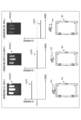
- FIG. 1 is a diagram for explaining a use case example of a biometric authentication system according to the first embodiment and a modified example of the first embodiment.
- FIG. 2 is a perspective view showing a first illumination arrangement example of the authentication device according to the first embodiment and the biometric information acquisition device according to the modified example of the first embodiment;
- FIG. 1 is a block diagram showing an example of an internal configuration of an authentication device according to a first embodiment;
- FIG. 1 is a diagram for explaining an example of exposure control in an authentication device.
- 1 is a timing chart showing an example of illumination control of an illumination device and exposure control of an image sensor;
- 1 is a timing chart showing an example of illumination control of an illumination device and exposure control of an image sensor;
- FIG. 1 is a diagram for explaining an example of a procedure for calculating fingerprint frequency. Diagram explaining examples of using biometric authentication systems
- FIG. 1 is a perspective view showing a second illumination arrangement example of the authentication device according to the first embodiment and the biometric information acquisition device according to a modified example of the first embodiment
- FIG. 13 is a perspective view showing a third example of an illumination arrangement of the authentication device according to the first embodiment and the biometric information acquisition device according to the modified example of the first embodiment.
- FIG. 1 is a diagram for explaining a first lighting example
- FIG. 13 is a diagram for explaining a second lighting example
- FIG. 13 is a diagram for explaining a third illumination example.
- FIG. 1 is a diagram for explaining a first lighting example
- FIG. 13 is a diagram for explaining a second lighting example
- FIG. 13 is a diagram for explaining a third illumination example.
- FIG. 13 is a perspective view showing a fourth example of an illumination arrangement of the authentication device according to the first embodiment and the biometric information acquisition device according to the modified example of the first embodiment.
- FIG. 4 is a diagram for explaining a fourth illumination example.
- FIG. 13 is a perspective view showing a fifth example of an illumination arrangement of the authentication device according to the first embodiment and the biometric information acquisition device according to the modified example of the first embodiment.
- FIG. 5 is a diagram for explaining a fifth lighting example.
- FIG. 1 is a block diagram showing an example of an internal configuration of an authentication device according to a modification of the first embodiment. A table showing the correspondence between each operation procedure shown in FIG. 7 and the operation procedure of the biometric authentication system according to each embodiment.
- FIG. 1 is a diagram illustrating an example of exposure control in a conventional authentication device.
- Fig. 21 is a diagram for explaining an example of exposure control in a conventional authentication device B1.
- the authentication device B1 shown in Fig. 21 has a similar configuration to the authentication device B1 described later.
- the authentication device B1 illuminates the user's hand UH, which is the subject of biometric authentication, with at least one illumination unit 30 (see FIG. 3), and captures an image of the user's hand UH with an imaging unit 40 (see FIG. 3).
- the authentication device B1 uses the captured image to perform biometric authentication (user authentication).
- the authentication device B1 captures the user's hand UH, which is stationary or moving, by controlling the illumination unit 30 and the imaging unit 40 under predetermined exposure conditions.
- Each of the captured images IMG01, IMG02, and IMG03 is an image of the hand UH captured by the authentication device B1.
- the captured image IMG01 is an image captured with the user's hand UH in contact with the glass surface 16 (see FIG. 1) of the authentication device B1, and is an image captured with the distance between the user's hand UH and the glass surface 16 (hereinafter referred to as the "imaging distance") at the shortest.
- the captured image IMG01 is an image captured with the user's hand UH in contact with the glass surface 16.
- the user's hand UH captured in the captured image IMG01 is overexposed due to the short imaging distance, and the image quality is degraded.
- the brightness graph LG01 shows the brightness value (hereinafter referred to as the "biometric brightness value") of the area of the user's hand UH captured in the captured image IMG01 from which biometric information used for biometric authentication is extracted.
- the biometric brightness value shown by the brightness graph LG01 is greater than the biometric brightness value Lm11 suitable for acquiring (extracting) biometric information used for biometric authentication. Therefore, the captured image IMG01 is an image that is not suitable for acquiring biometric information.
- Captured image IMG02 is an image captured when the user's hand UH is not in contact with the glass surface 16 of authentication device B1 and the imaging distance is appropriate.
- Brightness graph LG02 shows the biometric brightness value of captured image IMG02.
- the biometric brightness value shown by brightness graph LG02 is approximately equal to biometric brightness value Lm11 that is suitable for acquiring (extracting) biometric information to be used for biometric authentication.
- captured image IMG02 is an image that is suitable for acquiring biometric information.
- Captured image IMG03 is an image captured when the user's hand UH is not in contact with the glass surface 16 of authentication device B1 and the imaging distance is long.
- Brightness graph LG03 shows the biometric brightness value of captured image IMG03.
- the user's hand UH shown in captured image IMG03 is dark due to the long imaging distance, and image quality is degraded.
- the biometric brightness value shown by brightness graph LG03 is smaller than the biometric brightness value Lm11 that is suitable for acquiring (extracting) biometric information used for biometric authentication. Therefore, captured image IMG03 is an image that is not suitable for acquiring biometric information.
- the authentication device B1 that performs conventional exposure control, regardless of whether the user's hand UH is in contact with or not in contact with the imaging surface (glass surface 16), depending on the height at which the user holds his/her hand UH (i.e., imaging distance), the angle at which the user holds his/her hand UH, or the shape of each user's hand UH, etc., it may be difficult to obtain biometric information suitable for biometric authentication or to achieve more accurate biometric authentication.
- the user must repeatedly retake the image in order to capture an image from which biometric information suitable for biometric authentication can be obtained, which is very time-consuming.
- the direction along the optical axis OA of the imaging unit 40 is defined as the up-down direction.
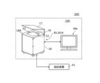
- FIG. 1 is a diagram for explaining an example of a use case of the biometric authentication systems 100 and 200 according to the first embodiment and the modified example of the first embodiment. Note that the biometric authentication system 100 according to the first embodiment will be described here, and the biometric authentication system 200 according to the modified example of the first embodiment will be described later.
- biometric authentication using mainly fingerprints as biometric information will be described, but the biometric information is not limited to this.
- the biometric information may be a user's fingerprint, palm print, finger or palm veins, etc.
- the biometric authentication system 100 includes an authentication device B1 and a monitor MN.
- the biometric authentication system 100 captures an image of at least a portion of a hand UH of a user who is to be authenticated (specifically, an area from which biometric information used for biometric authentication can be extracted) using the authentication device B1, and acquires the biometric information of the user that appears in the captured image.
- the biometric authentication system 100 also performs biometric authentication by using the authentication device B1 to match the user's biometric information with each of a number of pieces of biometric information registered in advance, and outputs the biometric authentication result to the monitor MN for display.
- the main example of imaging the user's hand UH will be a case where the user's hand UH is moving and not in contact with the glass surface 16 (i.e., the specified imaging surface), but this is not limiting.
- the user's hand UH may be imaged in a stationary state, or in contact with the glass surface 16 (i.e., the specified imaging surface).
- the monitor MN is configured using, for example, a Liquid Crystal Display (LCD) or an organic electroluminescence (EL).
- the monitor MN displays the matching result output from the authentication device B1, or outputs it as sound through a speaker (not shown).
- the monitor MN may be configured integrally with the authentication device B1.
- biometric authentication system 100 will be described as an example in which the authentication device B1 and the monitor MN are configured as separate entities, they may be configured as an integrated unit.
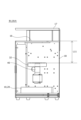
- Fig. 2 is a perspective view showing an example of a first illumination arrangement of authentication device B1 in embodiment 1 and biometric information acquisition device B1A in a modified example of embodiment 1.
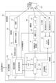
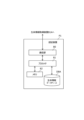
- Fig. 3 is a block diagram showing an example of the internal configuration of authentication device B1 according to embodiment 1.
- the authentication device B1 which is an example of a biometric image acquisition device, is made of metal or resin.
- the authentication device B1 includes a control unit 10, a glass surface 16 (see FIG. 1), a housing 18, an exposure control unit 20, an illumination unit 30, an imaging unit 40, a sensor unit 50, and a display control unit 60.
- the control unit 10 includes a processor 11, a memory 12, and a biometric information database DB.
- the processor 11 which is an example of an evaluation unit and acquisition unit, is configured using, for example, a Central Processing Unit (hereinafter referred to as "CPU"), a System-on-Chip (SOC) or a Field Programmable Gate Array (hereinafter referred to as "FPGA"), and performs various processes and controls in cooperation with the memory 12. Specifically, the processor 11 refers to the programs and data stored in the memory 12 and executes the programs to realize the functions of each unit, such as the control unit 10, the exposure control unit 20, the sensor unit 50, and the display control unit 60.
- CPU Central Processing Unit
- SOC System-on-Chip
- FPGA Field Programmable Gate Array
- the processor 11 causes the exposure control unit 20 to start controlling the illumination unit 30 and the imaging unit 40 based on the first detection signal output from the sensor unit 50, which notifies the detection of the user's hand UH.
- the processor 11 causes the exposure control unit 20 to end control of the illumination unit 30 and the imaging unit 40 based on the second detection signal output from the sensor unit 50, which notifies the detection of the user's hand UH.
- the processor 11 also detects the user's fingertip from the captured image captured by the imaging unit 40.
- the processor 11 generates a finger image by cutting out an area including at least the detected fingertip (e.g., the first joint).
- the processor 11 determines the priority of the finger images to be used for biometric authentication based on information such as the biometric brightness value of the generated finger image or the frequency of the unevenness of the fingerprint FP (hereinafter referred to as "fingerprint frequency"). Based on the determined priority, the processor 11 stores (registers) the user's biometric information in the biometric information database DB, and performs user authentication (i.e., biometric authentication) by comparing the biometric information of multiple users stored (registered) in advance in the biometric information database DB. The processor 11 outputs the biometric authentication result to the display control unit 60 and displays it on the monitor MN.
- the biometric information referred to here may be the finger image itself, or may be features extracted from the finger image that indicate the individuality of the user.
- Features are extracted using known techniques (e.g., the minutia method or frequency feature analysis method, etc.).
- the minutia method is a method for extracting fingerprint or palm print features by detecting the end points or branching points (divisions) that indicate breaks in the ridges of a fingerprint or palm print.
- the frequency feature analysis method is a method for extracting fingerprint or palm print features from a waveform of a frequency that is converted into a frequency based on the edges, bending points, etc. of the fingerprint unevenness.
- Vein features are extracted by extracting the vein pattern of a user's finger from an image of the user's finger captured using near-infrared light, for example.
- the memory 12 has, for example, a Random Access Memory (hereinafter referred to as "RAM") as a working memory used when executing each process of the processor 11 and the exposure control circuit 21, and a Flash Memory that stores programs and data that define the operation of the processor 11 and the exposure control circuit 21.
- RAM Random Access Memory
- Flash Memory stores programs and data that define the operation of the processor 11 and the exposure control circuit 21.
- the RAM temporarily stores data or information generated or acquired by the processor 11 or the exposure control circuit 21.
- the Flash Memory has written therein programs that define the operation of the processor 11 and the exposure control circuit 21.
- the memory 12 stores information regarding the exposure control of each of the illumination unit 30 and the imaging unit 40, which is executed by the exposure control unit 20.
- the information regarding the exposure control includes at least the illumination conditions for each of the multiple illumination areas of the illumination 32, such as the lighting pattern of the multiple illumination areas of the illumination 32, illumination conditions such as illumination emission time, the exposure control pattern of the imaging unit 40, exposure conditions such as exposure time, and the output pattern of the trigger signal of the illumination 32 or the imaging unit 40.
- the biometric information database DB is a storage medium device such as a hard disk drive (hereinafter referred to as an "HDD") or a solid state drive (hereinafter referred to as an "SSD”), and stores the biometric information of multiple users registered in advance by an administrator.
- the biometric information stored in the biometric information database DB is stored in association with user information (e.g., name, date of birth, identification number that can identify the user, employee number, or facial photograph, etc.).
- user information e.g., name, date of birth, identification number that can identify the user, employee number, or facial photograph, etc.
- the biometric information database DB may also store finger information (e.g., middle finger or index finger, etc.) corresponding to the biometric information in further association with the biometric information.
- biometric information database DB shown in FIG. 3 is an example configured integrally with the authentication device B1, it may also be configured as an external storage device separate from the authentication device B1 and connected to enable data transmission and reception via wireless or wired communication.
- Wireless communication here refers to communication via a wireless Local Area Network (LAN) such as Wi-Fi (registered trademark).
- LAN wireless Local Area Network
- the glass surface 16 (see FIG. 1) is disposed adjacent to at least one sensor (first approach sensor 51 or second approach sensor 52, see FIG. 1) on the top surface of the housing 18.
- the glass surface 16 is provided so that the lighting unit 30 can illuminate the user's hand UH passing over the housing top surface 18A (see FIG. 1) of the housing 18, and the image can be captured by the imaging unit 40.
- the cover guide 17 is made of metal or resin and is formed in a generally L-shape. One end of the generally L-shape of the cover guide 17 is fixed to one side of the rectangular housing top surface 18A. The other end of the generally L-shape of the cover guide 17 is provided to cover the housing top surface 18A, and blocks the illumination light from the illumination unit 30 that passes through the glass surface 16 of the housing top surface 18A at the other end side.
- the other end of the cover guide 17 is formed so that the distance (i.e., height) between the bottom surface of the cover guide 17 and the housing top surface 18A increases (is higher) from the side to which one end of the four sides of the housing top surface 18A is fixed toward the opposing side.
- the cover guide 17 has openings between the two sides adjacent to the side to which one end of the cover guide 17 is fixed (i.e., the side corresponding to the direction in which the user's finger enters and the side corresponding to the direction in which the user's finger leaves) and the other end of the cover guide 17. This allows the user to intuitively grasp the direction in which the user's finger should pass (i.e., either the passing direction X or the direction opposite to the passing direction X).
- the authentication device B1 can also use the cover guide 17 to limit the height of the user's hand UH, i.e., the imaging distance between the imaging unit 40 and the user's hand UH, to the distance between the cover guide 17 and the glass surface 16.
- the cover guide 17 is not an essential component of the authentication device B1 according to embodiment 1 and may be omitted.
- the exposure control unit 20 which is an example of a control unit, is configured using, for example, a CPU, SOC, or FPGA, and performs various processes and controls in cooperation with the memory 12. Specifically, the exposure control unit 20 references the programs and data stored in the memory 12 and executes the programs to realize the functions of the exposure control circuit 21.
- the exposure control unit 20 When the exposure control unit 20 acquires a control command output from the processor 11 and corresponding to the first detection signal, it executes illumination control of the illumination unit 30 and exposure control of the imaging unit 40 based on the information related to illumination control stored in the memory 12.
- the exposure control in this disclosure is control for adjusting the amount of light captured when the imaging unit 40 captures an image of the user's hand UH, such as control of the timing of opening and closing the shutter.
- the illumination control in this disclosure is time-division control of the illumination area that illuminates the user's hand UH during imaging, in other words, control for adjusting the illumination angle of the illumination 32 that illuminates the user's hand UH.
- the exposure control circuit 21 generates an illumination light emission signal for controlling each of the multiple illumination areas of the illumination 32, a shutter control signal for controlling the imaging sensor 42, etc., based on the illumination conditions or exposure conditions recorded in the memory 12.
- the exposure control circuit 21 outputs the generated illumination light emission signal to the illumination driver circuit 31.
- the exposure control circuit 21 also outputs the generated shutter control signal to the imaging sensor 42.
- the exposure control circuit 21 repeatedly executes the illumination control of the illumination unit 30 and the exposure control of the imaging unit 40 from the timing when it acquires a control command corresponding to the first detection signal to the timing when it acquires a control command corresponding to the second detection signal, and counts the number of times that the illumination control and exposure control are executed.
- the exposure control circuit 21 acquires a control command output from the processor 11 and corresponding to the first detection signal, it ends the illumination control of the illumination unit 30 and the exposure control of the imaging unit 40.
- the lighting unit 30 is stored inside the housing 18 of the authentication device B1 and illuminates the user's hand UH, which is the subject of the image capture unit 40.
- the lighting unit 30 includes a lighting driver circuit 31 and at least one light 32.
- the lighting driver circuit 31 performs ON/OFF control of the lighting 32 based on the control command output from the exposure control circuit 21.
- the lighting 32 is configured with one or more lights, such as a Light Emitting Diode (LED), a Laser Diode (LD), or an InfraRed (IR) light, and has multiple lighting areas (one example of a light-emitting area) that can be controlled to be turned on and off.
- FIG. 2 shows the lighting unit 30 formed in a circular ring shape as an example, but is not limited to this.
- the lighting 32 and each lighting area may be configured with any of a surface light source, a point light source, or a line light source, or may be configured by combining multiple different light sources among surface light sources, point light sources, or line light sources.
- the lighting 32 may be configured with multiple lights arranged in a polygonal shape, a substantially rectangular shape, a substantially circular ring shape, a substantially U-shaped shape, or a diamond shape, or may be configured with the lights arranged in approximately parallel.
- the lighting 32 may be configured with multiple lighting 32A, 32B (see FIG. 11) formed in a substantially annular shape, each having a different opening radius, and positioned at different distances from the glass surface 16.
- the lighting 32 may also be configured with at least one lighting 32C (see FIG. 15) formed in a substantially rectangular shape, or may be configured with at least one lighting 32D, 32E, 32F (see FIG. 17) formed in a substantially rectangular shape and at least one lighting 32G formed in a circular shape.
- the imaging unit 40 is stored inside the housing 18 of the authentication device B1 and captures an image of the user's hand UH passing over the glass surface 16.
- the imaging unit 40 includes a lens 41, an imaging sensor 42, and an imaging signal processing unit 43.
- the lens 41 forms an image of the light incident on the lens barrel (not shown) on the image sensor 42.
- the imaging sensor 42 is a so-called image sensor, and is, for example, a solid-state imaging element such as a Charged-Coupled Device (CCD) or Complementary Metal Oxide Semiconductor (CMOS).
- the imaging sensor 42 executes start and end control of an electronic shutter (not shown) (i.e., exposure start and end control) based on the shutter control signal output from the exposure control circuit 21.
- the imaging sensor 42 also converts the optical image formed on the imaging surface by the lens 41 into an electrical signal at a frame rate set in advance by the administrator, and outputs the signal to the imaging signal processing unit 43.
- the imaging signal processing unit 43 processes the electrical signal output from the imaging sensor 42 and outputs it to the processor 11.
- the sensor unit 50 includes a first approach sensor 51 and a second approach sensor 52 (see FIG. 1) as examples of a detection unit, and a sensor control circuit 53.
- Each of the first approach sensor 51 and the second approach sensor 52 is specifically realized by a reflective Time Of Flight (TOF) sensor, an infrared sensor, or a transmissive laser sensor, a light receiving sensor, or the like.
- TOF Time Of Flight
- Each of the first approach sensor 51 and the second approach sensor 52 is arranged in the passing direction X in which the user's fingers pass across the glass surface 16, and detects the user's hand UH passing through a predetermined detection area of each of the first approach sensor 51 and the second approach sensor 52.
- the first approach sensor 51 and the second approach sensor 52 detects the user's hand UH, it generates a detection signal and outputs it to the processor 11.
- FIG. 4 is a diagram for explaining an example of lighting control in the authentication device B1. It goes without saying that the example of lighting control shown in FIG. 4 is just one example and is not limiting.
- the exposure control unit 20 performs lighting control to switch the lighting area of the lighting 32 so that the biometric luminance value of the area of the user's hand UH shown in the captured image from which the biometric information features are extracted is approximately equal to the biometric luminance value Lm10 suitable for extracting biometric information, even if there is variation in the imaging distance between the user's hand UH and the imaging unit 40 (i.e., the height of the user's hand UH).
- the exposure control unit 20 executes lighting control corresponding to each of a plurality of exposure conditions stored in the memory 12 in a time-division manner, thereby capturing an image suitable for extracting the user's biometric information.
- the exposure control unit 20 switches between lighting controls corresponding to three lighting conditions in a time-division manner. For example, the exposure control unit 20 executes lighting control to illuminate a first lighting area corresponding to a first lighting condition in time period T11, executes lighting control to illuminate a second lighting area corresponding to a second lighting condition in time period T12, executes lighting control to illuminate a third lighting area corresponding to a third lighting condition in time period T13, and executes lighting control to illuminate the first lighting area corresponding to the first lighting condition in time period T14.
- the first lighting condition shown in Figure 4 is the lighting condition with the greatest amount of light.
- the second lighting condition is a lighting condition with less light than the first lighting condition, but more light than the third lighting condition.
- the third lighting condition is the lighting condition with the least amount of light.
- the luminance graph LG11 shows the biometric luminance value of the area of the user's hand UH captured in each of the four captured images captured in each of the time periods T11 to T14 from which biometric information used for biometric authentication is extracted when the imaging distance between the imaging unit 40 and the user's hand UH is close.
- the luminance graph LG11 shows a state in which the user's hand UH is in contact with the glass surface 16, and the biometric luminance value of the captured image IMG11 captured in the third lighting condition in the time period T13 is approximately equal to the biometric luminance value Lm10.
- the luminance graph LG12 shows the biometric luminance value of each of the four captured images taken in each of the time periods T11 to T14 when the imaging distance is appropriate.
- the biometric luminance value of the captured image IMG12 taken in the second lighting condition in time period T12 when the user's hand UH is not in contact with the glass surface 16 is approximately equal to the biometric luminance value Lm10.
- the luminance graph LG13 shows the biometric luminance value of each of the four captured images taken in each of the time periods T11 to T14 when the imaging distance is long.
- the user's hand UH is not in contact with the glass surface 16, and the biometric luminance value of the captured image IMG13 taken in the first lighting condition in the time periods T11 and T14 is approximately equal to the biometric luminance value Lm10.
- the authentication device B1 switches between the lighting areas that are controlled to be ON among the lighting areas of the lighting 32 in a time-division manner based on the multiple lighting conditions, and captures the user's hand UH illuminated under each lighting condition.
- the authentication device B1 can capture an image suitable for extracting biometric information even when the user's hand UH is in contact with or not in contact with the glass surface 16 and there is variation in the angle or height of the user's hand UH (i.e., the imaging distance).
- the authentication device B1 can capture an image of the user's hand UH under multiple different lighting conditions even when the user's hand UH is not in contact with the glass surface 16 or is moving on the glass surface 16 (i.e., not stationary), and therefore can capture an image suitable for extracting biometric information.
- the number of lighting conditions may be set arbitrarily based on the dynamic range of the imaging unit 40, the size of the imaging area that the imaging unit 40 can capture, the speed of the user's hand passing over the glass surface 16, etc. For example, when the dynamic range of the imaging unit 40 is small, the authentication device B1 can easily obtain an image closer to the biometric luminance value Lm10 suitable for extracting biometric information by increasing the number of lighting conditions.
- FIG. 5 is a timing chart showing an example of lighting control of the lighting 32 and an example of exposure control of the imaging sensor 42. It goes without saying that the lighting control example and exposure control example shown in FIG. 5 are merely examples and are not limited to these.
- the lighting 32 is composed of two lightings, "Lighting 1" and "Lighting 2", and an example will be described in which the lighting area corresponding to "Lighting 1" and the lighting area corresponding to "Lighting 2" are respectively controlled to be turned on and off.
- the exposure control unit 20 switches between the lighting control or exposure control based on each of the two lighting conditions in a time-division manner.
- the exposure control unit 20 executes lighting control of the lighting 32 in the order of the first lighting condition ⁇ the second lighting condition ⁇ the first lighting condition ⁇ the second lighting condition.
- the exposure control unit 20 executes lighting control or exposure control corresponding to a first lighting condition in time period T21-T22, lighting control or exposure control corresponding to a second lighting condition in time period T23-T24, lighting control or exposure control corresponding to the first lighting condition in time period T25-T26, and lighting control or exposure control corresponding to the second lighting condition in time period T27-T28.
- images captured under each of the two lighting conditions can be obtained by illuminating the user's hand UH from a number of different angles based on the position of the user's hand UH at each capture timing and the corresponding lighting conditions.
- the authentication device B1 can change the lighting angle at which the user's hand UH is illuminated by switching the lighting area, and can therefore acquire captured images with different exposures (light amounts). This allows the authentication device B1 to more efficiently acquire captured images of the user's hand UH captured at a brightness suitable for extracting biometric information (biometric luminance value or fingerprint frequency) even if the shape of the user's hand UH being imaged, the angle at which the user's hand UH passes through the imaging area of the imaging unit 40, the distance (height) of the user's hand UH from the glass surface 16, etc., vary each time.
- biometric information biometric luminance value or fingerprint frequency
- FIG. 6 is a timing chart showing an example of lighting control of the lighting 32 and exposure control of the image sensor 42. It goes without saying that the lighting control and exposure control example shown in FIG. 6 is merely an example and is not limited to this.
- the lighting 32 is composed of two lights, "Lighting 1" and "Lighting 2", and an example will be described in which the lighting area corresponding to "Lighting 1" and the lighting area corresponding to "Lighting 2" are respectively controlled to be turned on and off.
- the exposure control unit 20 switches between the lighting control or exposure control corresponding to each of the four lighting conditions in a time-division manner.
- the exposure control unit 20 executes lighting control of the lighting 32 in the order of the first lighting condition ⁇ the second lighting condition ⁇ the third lighting condition ⁇ the fourth lighting condition.
- the exposure control unit 20 repeatedly executes the illumination control of the illumination 32 and the exposure control of the imaging sensor 42 based on the above-mentioned exposure control pattern from the timing when it receives a control command output from the processor 11 to start illumination control or exposure control to the timing when it receives a control command to end illumination control or exposure control.
- the exposure control unit 20 executes lighting control corresponding to the first lighting condition in time period T31-T32, lighting control corresponding to the second lighting condition in time period T33-T34, lighting control corresponding to the third lighting condition in time period T35-T37, and lighting control corresponding to the fourth lighting condition in time period T38-T40.
- time period T33 time period T31. Note that the lighting 32 corresponding to "lighting 1" remains in the OFF state during time periods T33 to T34.
- time period T35 is less than time period T31. Note that the lighting 32 corresponding to "lighting 2" remains in the OFF state for time period T35 to T37.
- the authentication device B1 can change the lighting angle at which the user's hand UH is illuminated by switching the lighting area, and can therefore acquire captured images with different exposures (light amounts). This allows the authentication device B1 to more efficiently acquire captured images of the user's hand UH captured at a brightness suitable for extracting biometric information (biometric luminance value or fingerprint frequency) even if the shape of the user's hand UH being imaged, the angle at which the user's hand UH passes through the imaging area of the imaging unit 40, the distance (height) of the user's hand UH from the glass surface 16, etc., vary each time.
- biometric information biometric luminance value or fingerprint frequency
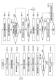
- Fig. 7 is a flowchart illustrating an example of the operation procedure of the biometric authentication system 100 according to the first embodiment.
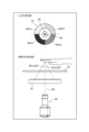
- Fig. 8 is a diagram illustrating an example of the calculation procedure of the fingerprint frequency.
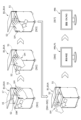
- Fig. 9 is a diagram illustrating an example of the use of the biometric authentication system 100.
- the following operation procedure describes an operation procedure executed when selecting a finger image to be registered for biometric information or biometric authentication based on the biometric luminance value or fingerprint frequency of the fingertip, but is not limited to this.
- the authentication device B1 may select a finger image to be registered for biometric information or biometric authentication based on either the biometric luminance value of the fingertip or the fingerprint frequency.
- the authentication device B1 may omit the processing of step St4-2.
- the authentication device B1 may omit the processing of step St4-1.
- the authentication device B1 detects the approach or insertion of the user's hand UH between the cover guide 17 and the glass surface 16 using one of the sensors (the first approach sensor 51 or the second approach sensor 52) (St1-1).
- the authentication device B1 starts lighting control corresponding to each of a plurality of pre-set lighting conditions from the timing when one of the sensors (first approach sensor 51 or second approach sensor 52) detects the approach or insertion of the user's hand UH (St2-1).
- the authentication device B1 starts emitting light from the light 32 and opening and closing the shutter of the image capture unit 40 based on the information about lighting control stored in the memory 12 (St2-3).
- the authentication device B1 captures an image of the user's hand UH at a shutter speed based on the nth lighting condition out of the k lighting conditions stored in the memory 12 (St3-1).
- the authentication device B1 stops the opening and closing of the shutter by the imaging unit 40 (St3-2) and increments the illumination control count number n (n+1) (St3-3).
- the authentication device B1 determines whether the incremented lighting control count number n is equal to the number k of lighting conditions (St3-4).
- step St3-4 determines in the processing of step St3-4 that the incremented lighting control count number n is not equal to the number k of lighting conditions (n ⁇ k) (St3-4, NO), it proceeds to the processing of step St4-1.
- the authentication device B1 detects the tip of at least one finger used for user authentication (biometric authentication) from the captured image (St4-1). Note that when performing vein authentication, the authentication device B1 detects at least one finger joint (e.g., the second joint, etc.), and when performing palm print authentication, it detects the palm.
- biometric authentication biometric authentication
- the authentication device B1 cuts out an area including at least a part of the detected fingertip to generate a finger image.
- the authentication device B1 calculates the biometric brightness value of the fingertip shown in the generated finger image (St4-1).
- the authentication device B1 cuts out an area including at least one finger joint (e.g., the second joint) to generate a vein image, and when performing palm print authentication, it cuts out an area including the palm to generate a palm image.
- the authentication device B1 cuts out an area including at least a part of the detected fingertip to generate a finger image Img1.
- the authentication device B1 performs image processing on the generated finger image Img1 to calculate the fingerprint frequency of the fingerprint FP appearing in the finger image (St4-2).
- authentication device B1 calculates the fingerprint frequency from at least a partial area of fingerprint FP appearing in finger image Img1.
- Authentication device B1 sets Q (Q: integer equal to or greater than 2) locations on lines HL1, HL2, ..., HLQ in a direction approximately perpendicular to the orientation of the finger appearing in finger image Img1.
- Authentication device B1 calculates the biometric brightness value of each pixel on the set Q locations of lines HL1 to HLQ.
- the authentication device B1 converts the light intensity received by the image sensor into a signal to obtain the bioluminance value of the surface of the fingertip.
- Graph LG21 shows the bioluminance value for each pixel on line HL1.
- the authentication device B1 performs low-pass filtering on the biometric luminance value of the fingerprint shown in graph LG21 to extract the base biometric luminance value of the fingertip (fingerprint) area (hereinafter referred to as the "base level").
- Graph LG22 shows the base level for each pixel on line HL1.
- the authentication device B1 subtracts the base level biometric luminance value (graph LG22) from the biometric luminance value of the fingertip surface (graph LG21) to extract a biometric luminance value corresponding to the unevenness of the fingerprint (hereinafter referred to as the "fingerprint level").
- Graph LG23 is a graph obtained by subtracting graph LG22 from graph LG21, and shows the fingerprint level on line HL1.
- the authentication device B1 calculates the absolute value of the extracted fingerprint level, and calculates the sum or average of the absolute values of the fingerprint level as the fingerprint frequency on the line HL1.
- the authentication device B1 sums up the fingerprint frequencies calculated for each of the Q lines HL1 to HLQ to calculate the fingerprint frequency of the fingerprint appearing in the finger image Img1 (St4-2).
- the authentication device B1 determines whether the calculated biometric luminance value of the fingertip is equal to or less than a first upper threshold limit and a first lower threshold limit indicating a biometric luminance value suitable for biometric authentication (fingerprint authentication), or whether the fingerprint frequency of the fingerprint captured in the finger image Img1 is equal to or greater than a second threshold limit indicating a fingerprint frequency suitable for biometric authentication (fingerprint authentication) (St4-3).
- the authentication device B1 determines that the calculated fingertip biometric luminance value is equal to or less than the first upper threshold value and equal to or less than the first lower threshold value, or that the calculated fingertip fingerprint frequency is equal to or greater than the second threshold value (St4-3, YES), it determines the priority order of each of the finger images to be registered in the biometric information database DB or the finger images to be used for biometric authentication based on the calculated fingertip biometric luminance value or fingerprint frequency.
- the authentication device B1 determines that the calculated biometric luminance value of the fingertip is equal to or less than the first upper threshold value and equal to or less than the first lower threshold value, it calculates the absolute value Br of the difference between the calculated biometric luminance value of the fingertip and an optimal value of the biometric luminance value of the fingertip suitable for biometric authentication (fingerprint authentication).
- the authentication device B1 may determine whether the calculated biometric luminance value of the fingertip is equal to or lower than a first upper threshold limit and a first lower threshold limit, which indicate that the biometric luminance value is suitable for biometric authentication (fingerprint authentication), and whether the fingerprint frequency of the fingerprint captured in the finger image Img1 is equal to or higher than a second threshold limit, which indicates that the fingerprint frequency is suitable for biometric authentication (fingerprint authentication).
- first weighting coefficient W1 and the second weighting coefficient W2 used to calculate the score may each be set to any parameter based on the installation environment of the authentication device B1 or the biometric information acquisition device B1A (e.g., the brightness around the imaging unit 40, the time of day, etc.).
- the authentication device B1 determines the priority order so that the finger image to be used for biometric authentication is ranked in descending order of the calculated score, and temporarily records the determined priority order information in memory 12 in association with the finger image (St4-4).
- the authentication device B1 determines in the processing of step St4-3 that the calculated biometric luminance value of the fingertip is not equal to or less than the first upper threshold value and not equal to or less than the first lower threshold value, and that the calculated fingerprint frequency of the fingertip is not equal to or greater than the second threshold value (St4-3, NO), it determines whether or not the other sensor has detected the user's hand UH (St4-5).
- step St4-4 If, in the processing of step St4-4, it is determined that the other sensor has detected the user's hand UH (St4-4, YES), the authentication device B1 ends the lighting control (St5-1).
- step St4-4 determines in the processing of step St4-4 that the other sensor has not detected the user's hand UH (St4-4, NO), it proceeds to the processing of step St2-3.
- the authentication device B1 performs registration or matching of the user's biometric information (biometric authentication) based on at least one temporarily stored finger image (St6-1).
- authentication device B1 When registering biometric information, authentication device B1 selects a finger image from the at least one temporarily stored finger image in order of priority, associates the user's biometric information (finger image or feature amount) corresponding to the finger image with user information (e.g., name, date of birth, identification number that can identify the user, employee number, or facial photograph, etc.), and stores (registers) them in the biometric information database DB (St6-1).
- user information e.g., name, date of birth, identification number that can identify the user, employee number, or facial photograph, etc.
- authentication device B1 may associate the user's biometric information, the user information, and finger information corresponding to the finger image (e.g., the middle finger of the right hand or the index finger of the left hand, etc.), and store (register) them in the biometric information database DB.
- the authentication device B1 selects a finger image from the at least one temporarily stored finger image in order of priority, and performs biometric authentication by comparing the user's biometric information corresponding to the finger image with the biometric information of at least one user registered in the biometric information database DB (St6-1).
- the authentication device B1 determines, in order of priority, whether the user's biometric information has already been registered in the biometric information database DB, or whether biometric information identical to or similar to the user's biometric information has already been registered in the biometric information database DB, based on the user's biometric information or user information and various information previously registered in the biometric information database DB (St6-2).
- the authentication device B1 When registering biometric information, the authentication device B1 repeatedly determines, in descending order of priority, whether the user information to be registered has already been registered in the biometric information database DB, and whether the biometric information to be registered (for example, a finger image or features of the middle finger of the right hand) has already been registered in the biometric information database DB (St6-2).
- step St6-2 determines in the processing of step St6-2 that the user information to be registered for any one of the temporarily stored finger images has not already been registered in the biometric information database DB and that the biometric information to be registered (for example, the finger image or feature amount of the middle finger of the right hand) has not already been registered in the biometric information database DB (St6-2, YES), it determines this finger image as the one to be registered and ends the processing of step St6-2.
- the authentication device B1 associates the user's biometric information (finger image or feature amount) with the user information and stores (registers) it in the biometric information database DB.
- the authentication device B1 generates a registration result screen notifying that the registration result (user registration result) is "OK” and displays it on the monitor MN (St7-1).
- the authentication device B1 determines in the processing of step St6-2 that the user information to be registered for all temporarily stored finger images has already been registered in the biometric information database DB, and that the biometric information to be registered (for example, the finger image or features of the middle finger of the right hand) has already been registered in the biometric information database DB (St6-2, NO), it generates a registration result screen notifying the user that the registration result (user registration result) is "NG” and displays it on the monitor MN (St7-2).
- the authentication device B1 determines whether biometric information identical to or similar to the user's biometric information has already been registered in the biometric information database DB, in descending order of priority (St6-2).
- step St6-2 the authentication device B1 determines that biometric information identical or similar to the user's biometric information has been registered in the biometric information database DB for any one of the temporarily stored finger images (St6-2, YES), the authentication device B1 ends the process of step St6-2.
- the authentication device B1 generates an authentication result screen notifying that the biometric authentication result (user authentication result) is "OK” and displays it on the monitor MN (St7-1). Note that the authentication device B1 may perform biometric authentication on each of multiple fingers.
- the authentication device B1 determines in the processing of step St6-2 that biometric information identical or similar to the user's biometric information has not been registered in the biometric information database DB for any of the temporarily stored finger images (St6-2, NO), it generates an authentication result screen notifying the user that the biometric authentication result (user authentication result) is "NG” and displays it on the monitor MN (St7-2).
- the authentication device B1 further calculates the absolute value of the difference between the average biometric luminance value for each pixel in the detected fingertip area and the optimal biometric luminance value of the fingertip suitable for biometric authentication (fingerprint authentication).
- the authentication device B1 may determine the priority order of finger images to be used for biometric authentication based on the absolute value of the calculated difference.
- the authentication device B1 further calculates the absolute value of the difference between the peak value of the biometric luminance value in the detected fingertip region and the optimal value of the biometric luminance value of the fingertip suitable for biometric authentication (fingerprint authentication).
- the authentication device B1 may determine the priority order of the finger images to be used for biometric authentication based on the absolute value of the calculated difference.
- the authentication device B1 extracts the biometric luminance values of the top V (V: an integer equal to or greater than 2) pixels with the largest biometric luminance values in the detected fingertip region, and further calculates the absolute value of the difference between the average biometric luminance value of the extracted V pixels and the optimal biometric luminance value of the fingertip suitable for biometric authentication (fingerprint authentication).
- the authentication device B1 may determine the priority order of finger images to be used for biometric authentication based on the absolute value of the calculated difference.
- authentication device B1 may calculate the fingerprint frequency on each line based on the sum or average of fingerprint levels at which the biometric luminance value is equal to or greater than the second threshold, or may calculate the number of pixels at which the biometric luminance value is equal to or greater than the second threshold as the fingerprint frequency on each line.
- the authentication device B1 may register or authenticate the biometric information of each of a plurality of different fingers. In such a case, the authentication device B1 registers or authenticates the biometric information in descending order of the determined priority. If the authentication device B1 determines that the registration or authentication is successful (i.e., "OK"), it registers or authenticates the biometric information in descending order of priority using biometric information associated with finger information different from the finger information corresponding to the biometric information for which registration or authentication was successful.
- the biometric authentication system 100 executes lighting control based on multiple lighting conditions set in advance, and captures an image of the user's hand UH. This allows the authentication device B1 to change the lighting area and obtain captured images of the user's hand UH illuminated at different lighting angles or illuminances. Therefore, the authentication device B1 can more efficiently obtain captured images captured at a brightness (biometric luminance value) suitable for extracting biometric information.
- the biometric authentication system 100 of the first embodiment can acquire a finger image more suitable for biometric authentication based on the biometric luminance value of the fingertip. Furthermore, the biometric authentication system 100 can register a finger image more suitable for biometric authentication or perform biometric authentication using a finger image more suitable for biometric authentication by determining a priority order based on the difference between the biometric luminance value of the fingertip based on the acquired finger image and the optimal biometric luminance value.
- the biometric authentication system 100 of embodiment 1 can acquire a finger image that is more suitable for biometric authentication based on the biometric luminance value of the fingertip or the biometric luminance value (light and dark) of the unevenness of the fingerprint. Furthermore, by determining the weighting coefficients W1 and W2, the biometric authentication system 100 can calculate a score indicating the degree to which the finger image is suitable for biometric authentication, and can select a finger image that is suitable for the installation environment of the authentication device B1 (imaging unit 40) and more suitable for biometric authentication. This allows the biometric authentication system 100 to improve the accuracy of biometric authentication.
- FIG. 10 is a perspective view showing a second lighting arrangement example of the authentication device B1 in the first embodiment and the biometric information acquisition device B1A in a modified example of the first embodiment.
- the lighting 32 (see FIG. 2) shown in the first lighting arrangement example is provided at any position (height) between the imaging unit 40 and the glass surface 16.
- the lighting 32 shown in the second lighting arrangement example has a distance L11 between the lighting 32 and the glass surface 16 that is approximately equal to the distance between the imaging unit 40 and the glass surface 16.
- the lighting 32 shown in the second lighting arrangement example is arranged so that the height of the lighting 32 is flush with the height of the lens 41 (not shown) of the imaging unit 40.
- the authentication device B1 or biometric information acquisition device B1A can suppress vignetting caused by the arrangement of the lighting 32.
- the lighting 32 in the second lighting arrangement example can increase the distance L11 between the imaging unit 40 and the glass surface 16, thereby making it possible to reduce the illumination angle of the user's hand UH passing over the glass surface 16. In other words, the lighting 32 can illuminate the user's hand UH from a more vertical direction.
- FIG. 11 is a perspective view showing a third example of the lighting arrangement of the authentication device B1 in the first embodiment and the biometric information acquisition device B1A in a modified example of the first embodiment.
- the lighting 32 shown in the third lighting arrangement example is composed of lighting 32A and 32B that are provided at different heights between the imaging unit 40 and the glass surface 16.
- Lighting 32A is an annular lighting with a larger opening diameter R21 than lighting 32B, and is arranged at a position where the distance from the glass surface 16 is distance L21.
- Lighting 32B is an annular lighting with a smaller opening diameter R22 than lighting 32A, and is arranged at a position where the distance from the glass surface 16 is distance L22. Note that distance L21 is smaller than distance L22.
- the authentication device B1 or biometric information acquisition device B1A can change the lighting angle at which the user's hand UH passes over the glass surface 16 by switching between the lights 32A and 32B.
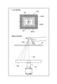
- FIG. 12 is a diagram for explaining the first lighting control example. Note that in the example shown in FIG. 12, in order to make the description easier to understand, only the glass surface 16, the lighting 32, and the image capture unit 40 are shown, and other components are not shown.
- top view refers to a view of the lighting 32 and the imaging unit 40, respectively, viewed from above the glass surface 16.
- side view refers to a view of the lighting 32 and the imaging unit 40, respectively, viewed from the direction in which the user's hand UH passes through the authentication device B1 and biometric information acquisition device B1A.
- the exposure control unit 20 turns on at least one of the different lighting areas AR11, AR12, and AR13 of the lighting 32.
- Each of the lighting areas AR11 to AR13 is annular-shaped area having a different distance from the center of the optical axis OA of the imaging unit 40.
- the exposure control unit 20 can illuminate the user's hand UH from the illumination angle corresponding to the illuminated illumination area by lighting each of the illumination areas AR11 to AR13 in the order of AR11, AR12, AR13 in a time-division manner toward the inner radius centered on the optical axis OA, or lighting each of the illumination areas AR13, AR12, AR11 in a time-division manner toward the outer radius centered on the optical axis OA.
- the exposure control unit 20 lights up the illumination area AR11, it illuminates the user's hand UH at an illumination angle ⁇ 11 centered on the optical axis OA
- the illumination area AR12 when the illumination area AR12 is turned on, it illuminates the user's hand UH at an illumination angle ⁇ 12 centered on the optical axis OA
- the illumination area AR13 when the illumination area AR13 is turned on, it illuminates the user's hand UH at an illumination angle ⁇ 13 centered on the optical axis OA.
- the exposure control unit 20 can change the lighting angle at which the user's hand UH passes over the glass surface 16 by switching the lighting areas of the lighting 32 that are turned on.
- the exposure control unit 20 can change the lighting angle at which the user's hand UH passes over the glass surface 16 by changing the combination of lighting areas of the lighting 32 that are turned on.
- FIG. 13 is a diagram for explaining the second lighting control example. Note that in the example shown in FIG. 13, in order to make the explanation easier to understand, only the glass surface 16, the lighting 32, and the image capture unit 40 are shown, and other components are not shown.
- the exposure control unit 20 turns on at least one of the different lighting areas AR21, AR22, AR23, and AR24 of the light 32.
- Each of the lighting areas AR21 to AR24 is an area obtained by dividing the area that can be illuminated by the annular light 32 into approximately four areas in the circumferential direction.
- the exposure control unit 20 can illuminate the user's hand UH from the illumination angle corresponding to the illuminated illumination areas by lighting each of the illumination areas AR21 to AR24 in a predetermined order (for example, clockwise or counterclockwise, or any other order).
- the exposure control unit 20 when the illumination area AR21 is turned on, the exposure control unit 20 illuminates the user's hand UH at an illumination angle ⁇ 21 relative to the optical axis OA; when the illumination area AR22 is turned on, the exposure control unit 20 illuminates the user's hand UH at an illumination angle ⁇ 22 relative to the optical axis OA in side view; when the illumination area AR23 is turned on, the exposure control unit 20 illuminates the user's hand UH at an illumination angle ⁇ 23 relative to the optical axis OA in side view; and when the illumination area AR24 is turned on, the exposure control unit 20 illuminates the user's hand UH at an illumination angle ⁇ 24 relative to the optical axis OA in side view.
- the predetermined order may be determined based on whether the first detection signal output from the sensor unit 50 is output from the first approach sensor 51 or the second approach sensor 52. For example, when the first detection signal is output from the first approach sensor 51, the exposure control unit 20 may determine the illumination order so that each of the multiple illumination areas is turned on in the direction from the first approach sensor 51 to the second approach sensor 52.
- the exposure control unit 20 can change the lighting angle at which the user's hand UH passes over the glass surface 16 by switching the lighting areas of the lighting 32 that are turned on.
- the exposure control unit 20 can change the lighting angle at which the user's hand UH passes over the glass surface 16 by changing the combination of lighting areas of the lighting 32 that are turned on.
- FIG. 14 is a diagram for explaining the third lighting control example. Note that in the example shown in FIG. 14, in order to make the explanation easier to understand, only the glass surface 16, the lighting 32A, 32B, and the image capture unit 40 are shown, and the other components are not shown.
- the exposure control unit 20 turns on each of the multiple lights 32A, 32B that make up the light 32 in a predetermined order, for example, light 32A, light 32B, light 32A, etc.
- the exposure control unit 20 may turn on two or more lighting areas simultaneously, for example, light 32A, light 32A and light 32B, light 32A, etc.
- the lighting area AR31 is a lighting area that can be illuminated by the annular light 32A.
- the lighting area AR32 is a lighting area that can be illuminated by the annular light 32B, and is a different area from the lighting area AR31 of the light 32A.
- the exposure control unit 20 can illuminate the user's hand UH from an illumination angle corresponding to the illuminated illumination by turning on at least one of the illuminations 32A and 32B. For example, when the exposure control unit 20 turns on the illumination 32A, it illuminates the user's hand UH at an illumination angle ⁇ 31 centered on the optical axis OA, and when the exposure control unit 20 turns on the illumination 32B, it illuminates the user's hand UH at an illumination angle ⁇ 32 centered on the optical axis OA.
- the exposure control unit 20 can change the lighting angle at which the user's hand UH passes over the glass surface 16 by switching which of the multiple lights 32A and 32B that make up the lighting 32 are turned on.
- each of the lights 32A and 32B may have multiple lighting areas as shown in Figures 12 and 13.
- the exposure control unit 20 may change the lighting angle at which the user's hand UH passing over the glass surface 16 is illuminated by changing the combination of lights and lighting areas to be turned on.
- FIG. 15 is a perspective view showing a fourth example of the lighting arrangement for the authentication device B1 in the first embodiment and the biometric information acquisition device B1A in a modified example of the first embodiment.
- the lighting 32C shown in the fourth lighting arrangement example is a lighting 32 formed in a substantially rectangular shape, and the distance L31 between the lighting 32C and the glass surface 16 is substantially equal to the distance between the intersection position (not shown) of the surface of the lens 41 (not shown) of the imaging unit 40 and the optical axis OA and the glass surface 16.
- the lighting 32C shown in the fourth lighting arrangement example is arranged so that the height of the lighting 32C and the height of the lens 41 (not shown) of the imaging unit 40 are flush with each other.
- the authentication device B1 and the biometric information acquisition device B1A can suppress vignetting caused by the arrangement of the illumination 32. Furthermore, by using the illumination 32C having a substantially rectangular shape, the authentication device B1 and the biometric information acquisition device B1A can suppress vignetting more effectively than when an illumination 32 having a circular ring shape is used.
- FIG. 16 is a diagram for explaining the fourth lighting control example. Note that in the example shown in FIG. 16, in order to make the explanation easier to understand, only the glass surface 16, lighting 32C, and image capture unit 40 are shown, and other components are omitted from the illustration. Also, in the example shown in FIG. 16, in order to make the drawing easier to understand, some lighting angles are omitted from the illustration.
- the exposure control unit 20 turns on at least one of the different lighting areas AR41, AR42, and AR43 of the lighting 32C.
- Each of the lighting areas AR41 to AR43 is an approximately rectangular frame-shaped area that is a different distance from the center of the optical axis OA of the imaging unit 40 within the area that can be illuminated by the lighting 32C.
- the exposure control unit 20 can illuminate the user's hand UH from the illumination angle corresponding to the illuminated illumination area by lighting each of the illumination areas AR41 to AR43 in the order of AR41, AR42, and AR43 in a time-division manner toward the inner radius centered on the optical axis OA, or lighting each of the illumination areas AR43, AR42, and AR41 in a time-division manner toward the outer radius centered on the optical axis OA.
- the exposure control unit 20 lights up the illumination area AR41, it illuminates the user's hand UH at an illumination angle ⁇ 41 centered on the optical axis OA
- the illumination area AR42 when the illumination area AR42 is turned on, it illuminates the user's hand UH at an illumination angle ⁇ 42 centered on the optical axis OA
- the illumination area AR43 when the illumination area AR43 is turned on, it illuminates the user's hand UH at an illumination angle ⁇ 43 centered on the optical axis OA.
- the exposure control unit 20 can change the lighting angle at which the user's hand UH passing over the glass surface 16 is illuminated by switching the lighting areas of the lighting 32C that are turned on.
- the exposure control unit 20 can change the lighting angle at which the user's hand UH passing over the glass surface 16 is illuminated by changing the combination of lighting areas of the lighting 32C that are turned on.
- FIG. 17 is a perspective view showing a fifth lighting arrangement example of the authentication device B1 in the first embodiment and the biometric information acquisition device B1A in a modified example of the first embodiment.
- the lighting 32 shown in the fifth lighting arrangement example is composed of multiple lighting elements 32D, 32E, and 32F each formed in a substantially rectangular shape, and lighting element 32G formed in a circular ring shape.
- Each of the multiple lighting elements 32D, 32E, and 32F is arranged in a U-shape at a position where the distance from the glass surface 16 is distance L41.
- Lighting element 32G is a circular ring-shaped lighting element, and is arranged at a position where the distance from the glass surface 16 is distance L42, which is substantially equal to the distance between the imaging unit 40 and the glass surface 16. Note that distance L41 is smaller than distance L42.
- Lighting element 32G is arranged so that the height of lighting element 32G is flush with the height of lens 41 (not shown) of imaging unit 40.
- the authentication device B1 or biometric information acquisition device B1A can suppress vignetting caused by the arrangement of the lights 32D-32F, which are at a greater distance from the imaging unit 40, i.e., at a smaller distance from the glass surface 16. Furthermore, by arranging each of the multiple lights 32D-32F in a U-shape, the authentication device B1 and biometric information acquisition device B1A can suppress vignetting more effectively than when a ring-shaped light 32 is used.
- the authentication device B1 or biometric information acquisition device B1A can increase the distance L42 between the imaging unit 40 and the glass surface 16 by using the lighting 32G, thereby making it possible to reduce the illumination angle of the user's hand UH passing over the glass surface 16.
- the lighting 32G can illuminate the user's hand UH from a more vertical direction.
- FIG. 18 is a diagram for explaining the fifth lighting control example. Note that in the example shown in FIG. 18, in order to make the explanation easier to understand, only the glass surface 16, lights 32D to 32G, and image capture unit 40 are shown, and other components are omitted. Also, in the example shown in FIG. 18, in order to make the figure easier to understand, some lighting angles are omitted from the illustration.
- the exposure control unit 20 turns on each of the multiple lights 32D to 32F in a predetermined order, for example, lights 32D, 32E, 32G, and 32F or lights 32F, 32G, 32E, and 32D.
- the lighting area AR51 is an illumination area that can be illuminated by the approximately rectangular lighting 32D.
- the lighting area AR52 is an illumination area that can be illuminated by the approximately rectangular lighting 32E.
- the lighting area AR53 is an illumination area that can be illuminated by the approximately rectangular lighting 32F.
- the lighting area AR54 is an illumination area that can be illuminated by the annular lighting 32G.
- the predetermined order may be determined based on whether the first detection signal output from the sensor unit 50 is output from the first approach sensor 51 or the second approach sensor 52. For example, when the first detection signal is output from the first approach sensor 51, the exposure control unit 20 may execute lighting control to turn on the lights 32F, 32E, 32G, and 32D in the order along the direction from the first approach sensor 51 to the second approach sensor 52.
- the exposure control unit 20 can illuminate the user's hand UH from an illumination angle corresponding to the illuminated illumination area by lighting up an illumination area corresponding to at least one of the illumination areas 32D to 32G.
- the exposure control unit 20 lights up the illumination area AR51, it illuminates the user's hand UH at an illumination angle ⁇ 51 relative to the optical axis OA in a side view
- the exposure control unit 20 lights up the illumination area AR52, it illuminates the user's hand UH at an illumination angle ⁇ 52 relative to the optical axis OA in a side view
- the exposure control unit 20 lights up the illumination area AR53
- the exposure control unit 20 lights up the illumination area AR54, it illuminates the user's hand UH at an illumination angle ⁇ 54 relative to the optical axis OA in a side view.
- the exposure control unit 20 can change the lighting angle at which the user's hand UH passes over the glass surface 16 by switching which lights are turned on among the lighting areas corresponding to the multiple lights 32D to 32G.
- the exposure control unit 20 can change the lighting angle at which the user's hand UH passes over the glass surface 16 by changing the combination of lights that are turned on among the multiple lights 32D to 32G.
- the exposure control unit 20 may also determine the illumination areas to be lit and the predetermined order based on the body parts used for biometric authentication. For example, when biometric authentication is performed using a fingerprint or vein, the exposure control unit 20 may execute illumination control to turn on the illuminations 32F, 32E, and 32D in that order to easily illuminate the user's fingertips, and when biometric authentication is performed using a palm print, the exposure control unit 20 may execute illumination control to turn on the illuminations 32F, 32G, and 32D in that order to easily illuminate the user's palm. This allows the exposure control unit 20 to more effectively obtain captured images that are more suitable for biometric authentication, regardless of the angle of the user's hand UH, etc.
- the biometric authentication system 100 according to the first embodiment described above has been an example in which the authentication device B1 captures an image of the user's hand UH, performs biometric authentication, and displays the biometric authentication result on the monitor MN.
- the biometric authentication system 200 according to the modified example of the first embodiment will be described as an example in which the biometric information acquisition device B1A captures an image of the user's hand UH, the authentication device P1 performs biometric authentication, and the monitor MN displays the biometric authentication result.
- the same reference numerals will be used to designate components similar to those of the devices constituting the biometric authentication system 100 according to the first embodiment, and description thereof will be omitted.
- the biometric authentication system 200 includes a biometric information acquisition device B1A (an example of a biometric image acquisition device), an authentication device P1, and a monitor MN.
- the biometric authentication system 200 captures an image of a user's hand or part of the hand UH using the biometric information acquisition device B1A, acquires the user's biometric information shown in the captured image, and transmits it to the authentication device P1 connected so as to be able to transmit and receive data between the biometric information acquisition device B1A.
- the biometric authentication system 200 also performs biometric authentication by using the authentication device P1 to match the user's biometric information with each of a number of pieces of biometric information registered in advance, and transmits the biometric authentication result to the biometric information acquisition device B1A.
- the biometric authentication system 200 generates an authentication result screen that notifies the user of the biometric authentication result using the biometric information acquisition device B1A, and outputs and displays it on the monitor MN.
- biometric authentication system 200 will be described as an example in which the biometric information acquisition device B1A and the monitor MN are configured as separate entities, they may be configured as an integrated unit.
- the biometric information acquisition device B1A and the authentication device P1 may be connected to each other via a network (not shown) so that data can be transmitted and received, or may be connected to each other via, for example, a wired cable or the like so that data can be transmitted and received.
- FIG. 19 is a block diagram showing an example of the internal configuration of the authentication device P1 according to a modified example of the first embodiment.
- the authentication device P1 includes a communication unit 80, a processor 81, a memory 82, and a biometric information database DBA.
- the biometric information database DBA may be configured separately from the authentication device P1 and connected to the authentication device P1 so that data can be transmitted and received between them.
- the communication unit 80 is connected to the communication unit 70 in the biometric information acquisition device B1A for wireless or wired communication and transmits and receives data.
- the communication unit 80 acquires the user's biometric information transmitted from the biometric information acquisition device B1A and outputs it to the processor 81.
- the communication unit 80 also transmits the biometric authentication result information output from the processor 81 to the biometric information acquisition device B1A.
- Processor 81 is configured using, for example, a CPU, SOC, or FPGA, and performs various processes and controls in cooperation with memory 82. Specifically, processor 81 references the programs and data stored in memory 82 and executes the programs to realize the functions of each part.
- the processor 81 performs user authentication using biometric information (i.e., biometric authentication) based on the user's biometric information and the biometric information of each of multiple users preregistered (stored) in the biometric information database DBA.
- biometric authentication i.e., biometric authentication
- the processor 81 generates a biometric authentication result, outputs the information on the biometric authentication result to the communication unit 80, and transmits it to the biometric information acquisition device B1A.
- Memory 82 has, for example, a RAM as a work memory used when executing each process of processor 81, and a flash memory that stores programs and data that define the operation of processor 81. Data or information generated or acquired by processor 81 is temporarily stored in the RAM. Programs that define the operation of processor 81 are written in the flash memory.
- the biometric information database DBA is a storage media device such as a HDD or SSD, and stores the biometric information of multiple users registered in advance by an administrator.
- the biometric information stored in the biometric information database DBA is stored in association with user information (e.g., name, date of birth, identification number that can identify the user, employee number, or facial photograph, etc.).
- user information e.g., name, date of birth, identification number that can identify the user, employee number, or facial photograph, etc.
- the biometric information database DBA may also store finger information (e.g., middle finger or index finger, etc.) corresponding to the biometric information in further association with the biometric information.
- FIG. 20 is a table TB1 showing the correspondence between the operation procedure shown in FIG. 7 and the operation procedure of the biometric authentication systems 100 and 200 according to each embodiment.
- the biometric authentication system 100 executes the processes of steps St1-1 to St6-2 using the authentication device B1, and executes the processes of steps St7-1 to St7-2 using the monitor MN.
- the biometric information acquisition device B1A executes the processes of steps St1-1 to St5-1
- the authentication device P1 executes the processes of steps St6-1 to St6-2
- the monitor MN executes the processes of steps St7-1 to St7-2.
- the authentication device B1 (an example of a biometric image acquisition device) according to the first embodiment includes a light 32 (illumination unit 30) having a plurality of illumination areas (an example of a light-emitting area), an imaging unit 40 that images at least a portion of the user's hand, and a processor 11 (an example of an acquisition unit) that selects and acquires at least one captured image (e.g., a finger image) from a plurality of captured images (an example of a frame) captured while each of the different illumination areas is emitting light.
- the computer referred to here is the authentication device B1.
- the authentication device B1 can more efficiently acquire an image of the user's hand UH captured at a brightness (biometric luminance value or fingerprint frequency) suitable for extracting biometric information, even if the shape of the user's hand UH being captured, the angle at which the user's hand UH passes through the imaging area of the imaging unit 40, the distance (height) of the user's hand UH from the glass surface 16, etc., vary each time.
- a brightness biometric luminance value or fingerprint frequency
- the authentication device B1 according to the first embodiment further includes a first approach sensor 51 and a second approach sensor 52 (an example of a detection unit) that detect the hand of the user (an example of a person to be authenticated).
- the exposure control unit 20 causes at least one of the multiple illumination areas to emit light based on the detection of the user's hand. This allows the authentication device B1 according to the first embodiment to illuminate the user's hand UH only when it detects the user's hand UH to be imaged.
- the exposure control unit 20 of the authentication device B1 according to the first embodiment changes the illuminated area to be illuminated in a time-division manner. This allows the authentication device B1 according to the first embodiment to realize switching control (i.e., illumination control) of the illuminated area to be illuminated (emitted) in each time period, and to obtain captured images captured with different illumination angles or amounts of light.
- switching control i.e., illumination control
- the exposure control unit 20 of the authentication device B1 according to the first embodiment changes the exposure conditions (exposure parameters) of the imaging unit 40 for each captured image of the imaging unit 40. This allows the authentication device B1 according to the first embodiment to realize switching control of the illumination area to be illuminated (emitted light) (i.e., illumination control) and exposure control of the imaging unit 40, and to obtain captured images captured at different illumination angles or amounts of light.
- the exposure control unit 20 of the authentication device B1 according to the first embodiment illuminates the illumination area based on the direction in which the user's hand moves. This allows the authentication device B1 according to the first embodiment to more effectively illuminate the parts used for biometric authentication (e.g., fingerprints, veins, palm prints, etc.) and more efficiently acquire an image of the user's hand UH captured at a brightness suitable for extracting biometric information (biometric luminance value or fingerprint frequency).
- biometric authentication e.g., fingerprints, veins, palm prints, etc.
- the authentication device B1 further includes a first approach sensor 51 and a second approach sensor 52 (an example of a detection unit) that detect the hand of a user (an example of a person to be authenticated).
- the first approach sensor 51 and the second approach sensor 52 each have two sensors, the first approach sensor 51 and the second approach sensor 52.
- the exposure control unit 20 estimates the movement direction of the user's hand based on whichever sensor detects the user's hand.
- the authentication device B1 according to the first embodiment to realize lighting control that is more suitable for the part used for biometric authentication (e.g., fingerprint, vein, palm print, etc.), and more efficiently acquire an image of the user's hand UH captured at a brightness (biometric luminance value or fingerprint frequency) suitable for extracting biometric information.
- biometric authentication e.g., fingerprint, vein, palm print, etc.
- the illumination 32 of the authentication device B1 according to embodiment 1 has a plurality of illumination areas arranged on a horizontal plane that is between the imaging unit 40 and the user's hand in a direction along the optical axis of the imaging unit 40 and is approximately perpendicular to the optical axis OA.
- This allows the authentication device B1 according to embodiment 1 to illuminate the user's hand UH (i.e., the parts used for biometric authentication (e.g., fingerprints, veins, palm prints, etc.)) from different angles. Therefore, the authentication device B1 can more efficiently acquire an image of the user's hand UH captured at a brightness suitable for extracting biometric information (biometric luminance value or fingerprint frequency) even if the angle of the user's hand UH is different each time.
- biometric information biometric luminance value or fingerprint frequency
- the illumination 32 of the authentication device B1 according to embodiment 1 has multiple illumination areas arranged at different positions between the imaging unit 40 and the user's hand in the direction along the optical axis OA of the imaging unit 40.
- the authentication device B1 according to embodiment 1 can obtain multiple captured images each captured with a different amount of light (brightness) by changing the distance between the height of the user's hand UH and the multiple illumination areas. Therefore, the authentication device B1 can more efficiently obtain captured images of the user's hand UH captured with a brightness suitable for extracting biometric information (biometric luminance value or fingerprint frequency) even if the distance (height) of the user's hand UH from the glass surface 16 is different each time.
- biometric information biometric luminance value or fingerprint frequency
- the lens of the imaging unit 40 and at least one of the multiple illumination areas are arranged at approximately the same height. This allows the authentication device B1 according to the first embodiment to suppress vignetting caused by the arrangement of the illumination 32.
- the illumination 32 of the authentication device B1 according to embodiment 1 has a plurality of illumination areas formed in concentric circles centered on the optical axis OA of the imaging unit 40.
- the exposure control unit 20 causes the illumination areas to emit light in a time-division manner in a direction away from the optical axis OA based on detection of the user's hand.
- This allows the authentication device B1 according to embodiment 1 to illuminate the user's hand UH (i.e., the parts used for biometric authentication (e.g., fingerprints, veins, palm prints, etc.)) from different angles. Therefore, the authentication device B1 can more efficiently acquire images of the user's hand UH captured at a brightness suitable for extracting biometric information (biometric luminance value or fingerprint frequency) even if the angle of the user's hand UH is different each time.
- biometric information biometric luminance value or fingerprint frequency
- the illumination 32 of the authentication device B1 according to embodiment 1 has multiple illumination areas formed in concentric circles centered on the optical axis OA of the imaging unit 40.
- the exposure control unit 20 causes the illumination areas to emit light in a time-division manner in a direction approaching the optical axis based on detection of the user's hand.
- This allows the authentication device B1 according to embodiment 1 to illuminate the user's hand UH (i.e., the parts used for biometric authentication (e.g., fingerprints, veins, palm prints, etc.)) from different angles. Therefore, the authentication device B1 can more efficiently acquire images of the user's hand UH captured at a brightness suitable for extracting biometric information (biometric luminance value or fingerprint frequency) even if the angle of the user's hand UH is different each time.
- biometric information biometric luminance value or fingerprint frequency
- the illumination 32 of the authentication device B1 according to embodiment 1 is formed in a substantially circular ring shape centered on the optical axis OA of the imaging unit 40, and has multiple illumination areas along the circumferential direction of the ring.
- the exposure control unit 20 causes the multiple illumination areas to emit light in a predetermined order.
- the authentication device B1 according to embodiment 1 to illuminate the user's hand UH (i.e., the parts used for biometric authentication (e.g., fingerprints, veins, palm prints, etc.)) from different angles. Therefore, the authentication device B1 can more efficiently acquire an image of the user's hand UH captured at a brightness suitable for extracting biometric information (biometric luminance value or fingerprint frequency) even if the angle of the user's hand UH is different each time.
- biometric information biometric luminance value or fingerprint frequency
- the authentication device B1 according to the first embodiment further includes a processor 11 (an example of an evaluation unit) that evaluates the fingerprint level (an example of a pattern level) of the hand appearing in the captured images.
- the processor 11 selects at least one captured image to be acquired based on the evaluated fingerprint level of the hand.
- the authentication device B1 according to the first embodiment can more efficiently acquire captured images captured at a brightness (biometric brightness value or fingerprint frequency) suitable for extracting biometric information based on the brightness of the user's hand UH appearing in the captured images, even if the shape of the captured user's hand UH, the angle of the user's hand UH passing through the imaging area of the imaging unit 40, the distance (height) of the user's hand UH from the glass surface 16, etc. vary each time.
- the biometric authentication system 200 includes a biometric information acquisition device B1A (an example of a biometric image acquisition device) that acquires an image (an example of a frame) of at least a part of a user's (an example of a person to be authenticated) hand, and an authentication device P1 that can communicate with the biometric information acquisition device B1A.
- a biometric information acquisition device B1A an example of a biometric image acquisition device
- an authentication device P1 that can communicate with the biometric information acquisition device B1A.
- the biometric information acquisition device B1A illuminates at least one of a plurality of illumination areas (an example of a light-emitting area) of the illumination 32 (illumination unit 30), captures an image of at least a part of the user's hand UH, and selects at least one of the plurality of images captured while the different illumination areas are emitting light, and transmits it to the authentication device P1.
- the authentication device P1 authenticates the person to be authenticated based on the image (e.g., a finger image) transmitted from the biometric information acquisition device B1A.
- the biometric authentication system 200 can more efficiently acquire an image of the user's hand UH captured at a brightness (biometric luminance value or fingerprint frequency) suitable for extracting biometric information, even if the shape of the user's hand UH being imaged, the angle at which the user's hand UH passes through the imaging area of the imaging unit 40, the distance (height) of the user's hand UH from the glass surface 16, etc. vary each time.
- a brightness biometric luminance value or fingerprint frequency
- the present disclosure is useful as a biometric image acquisition device, a biometric image acquisition method, and a biometric authentication system that acquire images more suitable for biometric authentication.
- Control unit 11 Control unit 11, 81 Processor 12, 82 Memory 17 Cover guide 18 Housing 18A Housing top surface 20 Exposure control unit 30 Illumination unit 32, 32A, 32B, 32C, 32D, 32E, 32F, 32G Illumination 40 Imaging unit 41 Lens 42 Imaging sensor 50 Sensor unit 51 First approach sensor 52 Second approach sensor 60 Display control unit 100, 200 Biometric authentication system AR11, AR12, AR13, AR21, AR22, AR23, AR24, AR31, AR32, AR41, AR42, AR43, AR51, AR52, AR53, AR54 Illumination area B1 Authentication device B1A Biometric information acquisition device DB, DBA Biometric information database IMG01, IMG02, IMG03, IMG11, IMG12, IMG13 Captured image MN Monitor P1 Authentication device
Landscapes
- Engineering & Computer Science (AREA)
- Health & Medical Sciences (AREA)
- Physics & Mathematics (AREA)
- Life Sciences & Earth Sciences (AREA)
- General Physics & Mathematics (AREA)
- Multimedia (AREA)
- Theoretical Computer Science (AREA)
- General Health & Medical Sciences (AREA)
- Human Computer Interaction (AREA)
- Biophysics (AREA)
- Vascular Medicine (AREA)
- Pathology (AREA)
- Biomedical Technology (AREA)
- Heart & Thoracic Surgery (AREA)
- Medical Informatics (AREA)
- Molecular Biology (AREA)
- Surgery (AREA)
- Animal Behavior & Ethology (AREA)
- Public Health (AREA)
- Veterinary Medicine (AREA)
- Image Input (AREA)
Priority Applications (1)
| Application Number | Priority Date | Filing Date | Title |
|---|---|---|---|
| JP2025516829A JPWO2024225283A1 (https=) | 2023-04-24 | 2024-04-23 |
Applications Claiming Priority (2)
| Application Number | Priority Date | Filing Date | Title |
|---|---|---|---|
| JP2023070990 | 2023-04-24 | ||
| JP2023-070990 | 2023-04-24 |
Publications (1)
| Publication Number | Publication Date |
|---|---|
| WO2024225283A1 true WO2024225283A1 (ja) | 2024-10-31 |
Family
ID=93256506
Family Applications (1)
| Application Number | Title | Priority Date | Filing Date |
|---|---|---|---|
| PCT/JP2024/015954 Ceased WO2024225283A1 (ja) | 2023-04-24 | 2024-04-23 | 生体画像取得装置、生体画像取得方法および生体認証システム |
Country Status (2)
| Country | Link |
|---|---|
| JP (1) | JPWO2024225283A1 (https=) |
| WO (1) | WO2024225283A1 (https=) |
Citations (4)
| Publication number | Priority date | Publication date | Assignee | Title |
|---|---|---|---|---|
| JP2004280383A (ja) * | 2003-03-14 | 2004-10-07 | Canon Inc | 認証装置、認証方法、及びコンピュ−タ読み取り可能な記憶媒体、プログラム |
| JP2017162302A (ja) * | 2016-03-10 | 2017-09-14 | 富士通株式会社 | 生体認証装置、生体認証方法および生体認証プログラム |
| JP2022072908A (ja) * | 2020-10-30 | 2022-05-17 | パナソニックIpマネジメント株式会社 | 生体情報取得装置、生体認証装置および生体情報取得方法 |
| WO2022196154A1 (ja) * | 2021-03-16 | 2022-09-22 | パナソニックIpマネジメント株式会社 | 非接触認証システムおよび認証方法 |
-
2024
- 2024-04-23 JP JP2025516829A patent/JPWO2024225283A1/ja active Pending
- 2024-04-23 WO PCT/JP2024/015954 patent/WO2024225283A1/ja not_active Ceased
Patent Citations (4)
| Publication number | Priority date | Publication date | Assignee | Title |
|---|---|---|---|---|
| JP2004280383A (ja) * | 2003-03-14 | 2004-10-07 | Canon Inc | 認証装置、認証方法、及びコンピュ−タ読み取り可能な記憶媒体、プログラム |
| JP2017162302A (ja) * | 2016-03-10 | 2017-09-14 | 富士通株式会社 | 生体認証装置、生体認証方法および生体認証プログラム |
| JP2022072908A (ja) * | 2020-10-30 | 2022-05-17 | パナソニックIpマネジメント株式会社 | 生体情報取得装置、生体認証装置および生体情報取得方法 |
| WO2022196154A1 (ja) * | 2021-03-16 | 2022-09-22 | パナソニックIpマネジメント株式会社 | 非接触認証システムおよび認証方法 |
Also Published As
| Publication number | Publication date |
|---|---|
| JPWO2024225283A1 (https=) | 2024-10-31 |
Similar Documents
| Publication | Publication Date | Title |
|---|---|---|
| TWI533224B (zh) | 眼球偵測裝置、瞳孔偵測方法與虹膜辨識方法 | |
| US20140253711A1 (en) | Agile non-contact biometric sensor | |
| KR100854890B1 (ko) | 홍채 인식 시스템의 다중 조명을 이용한 홍채 등록 및인식방법 | |
| KR101413413B1 (ko) | 이물 판정 장치, 이물 판정 방법 및 이물 판정 프로그램 | |
| EP2120183B1 (en) | Method and system for cancellation of ambient light using light frequency | |
| US20100231712A1 (en) | Image capturing apparatus and image capturing method | |
| CN104685318A (zh) | 具有多个光源的运动传感器装置 | |
| US11687635B2 (en) | Automatic exposure and gain control for face authentication | |
| US20130223679A1 (en) | Movement analysis and/or tracking system | |
| US11164337B2 (en) | Autocalibration for multiple cameras using near-infrared illuminators | |
| US10667445B2 (en) | Position recognition apparatus for printed circuit board, position recognition and processing apparatus, and printed circuit board manufacturing method | |
| US10346673B2 (en) | Biometric authentication device, biometric authentication method, and computer-readable non-transitory medium | |
| CN105358045A (zh) | 眼凝视成像 | |
| KR20080052398A (ko) | 이동식 영상 카메라를 구비한 제스처 인식 시스템 | |
| US20060238643A1 (en) | Exposure control system and method for an image sensor | |
| CN104657702B (zh) | 眼球侦测装置、瞳孔侦测方法与虹膜辨识方法 | |
| WO2013104313A1 (zh) | 一种用于检测输入设备的三维位置信息的方法与系统 | |
| JP7228885B2 (ja) | 瞳孔検出装置 | |
| WO2024225283A1 (ja) | 生体画像取得装置、生体画像取得方法および生体認証システム | |
| JP2004062846A (ja) | 個人識別装置の入力装置 | |
| US8079714B2 (en) | Projector and method for acquiring coordinate of bright spot | |
| US9342164B2 (en) | Motion detecting device and the method for dynamically adjusting image sensing area thereof | |
| WO2024225282A1 (ja) | 生体画像取得装置、生体画像取得方法および生体認証システム | |
| US9686458B2 (en) | Camera LED flash with variable lens gain | |
| JP2025022142A (ja) | 生体画像取得装置、生体画像取得方法および生体認証システム |
Legal Events
| Date | Code | Title | Description |
|---|---|---|---|
| 121 | Ep: the epo has been informed by wipo that ep was designated in this application |
Ref document number: 24797029 Country of ref document: EP Kind code of ref document: A1 |
|
| ENP | Entry into the national phase |
Ref document number: 2025516829 Country of ref document: JP Kind code of ref document: A |
|
| WWE | Wipo information: entry into national phase |
Ref document number: 2025516829 Country of ref document: JP |
|
| NENP | Non-entry into the national phase |
Ref country code: DE |