WO2024224608A1 - 映像共有システム及び映像共有方法 - Google Patents
映像共有システム及び映像共有方法 Download PDFInfo
- Publication number
- WO2024224608A1 WO2024224608A1 PCT/JP2023/016895 JP2023016895W WO2024224608A1 WO 2024224608 A1 WO2024224608 A1 WO 2024224608A1 JP 2023016895 W JP2023016895 W JP 2023016895W WO 2024224608 A1 WO2024224608 A1 WO 2024224608A1
- Authority
- WO
- WIPO (PCT)
- Prior art keywords
- information terminal
- portable information
- display
- terminal
- image
- Prior art date
- Legal status (The legal status is an assumption and is not a legal conclusion. Google has not performed a legal analysis and makes no representation as to the accuracy of the status listed.)
- Ceased
Links
Images








Classifications
-
- H—ELECTRICITY
- H04—ELECTRIC COMMUNICATION TECHNIQUE
- H04N—PICTORIAL COMMUNICATION, e.g. TELEVISION
- H04N21/00—Selective content distribution, e.g. interactive television or video on demand [VOD]
- H04N21/40—Client devices specifically adapted for the reception of or interaction with content, e.g. set-top-box [STB]; Operations thereof
- H04N21/41—Structure of client; Structure of client peripherals
- H04N21/414—Specialised client platforms, e.g. receiver in car or embedded in a mobile appliance
- H04N21/41407—Specialised client platforms, e.g. receiver in car or embedded in a mobile appliance embedded in a portable device, e.g. video client on a mobile phone, PDA, laptop
-
- H—ELECTRICITY
- H04—ELECTRIC COMMUNICATION TECHNIQUE
- H04N—PICTORIAL COMMUNICATION, e.g. TELEVISION
- H04N21/00—Selective content distribution, e.g. interactive television or video on demand [VOD]
- H04N21/40—Client devices specifically adapted for the reception of or interaction with content, e.g. set-top-box [STB]; Operations thereof
- H04N21/41—Structure of client; Structure of client peripherals
- H04N21/422—Input-only peripherals, i.e. input devices connected to specially adapted client devices, e.g. global positioning system [GPS]
- H04N21/4223—Cameras
-
- H—ELECTRICITY
- H04—ELECTRIC COMMUNICATION TECHNIQUE
- H04N—PICTORIAL COMMUNICATION, e.g. TELEVISION
- H04N21/00—Selective content distribution, e.g. interactive television or video on demand [VOD]
- H04N21/40—Client devices specifically adapted for the reception of or interaction with content, e.g. set-top-box [STB]; Operations thereof
- H04N21/43—Processing of content or additional data, e.g. demultiplexing additional data from a digital video stream; Elementary client operations, e.g. monitoring of home network or synchronising decoder's clock; Client middleware
- H04N21/442—Monitoring of processes or resources, e.g. detecting the failure of a recording device, monitoring the downstream bandwidth, the number of times a movie has been viewed, the storage space available from the internal hard disk
- H04N21/44213—Monitoring of end-user related data
- H04N21/44218—Detecting physical presence or behaviour of the user, e.g. using sensors to detect if the user is leaving the room or changes his face expression during a TV programme
-
- H—ELECTRICITY
- H04—ELECTRIC COMMUNICATION TECHNIQUE
- H04N—PICTORIAL COMMUNICATION, e.g. TELEVISION
- H04N21/00—Selective content distribution, e.g. interactive television or video on demand [VOD]
- H04N21/40—Client devices specifically adapted for the reception of or interaction with content, e.g. set-top-box [STB]; Operations thereof
- H04N21/47—End-user applications
- H04N21/478—Supplemental services, e.g. displaying phone caller identification, shopping application
- H04N21/4788—Supplemental services, e.g. displaying phone caller identification, shopping application communicating with other users, e.g. chatting
-
- H—ELECTRICITY
- H04—ELECTRIC COMMUNICATION TECHNIQUE
- H04N—PICTORIAL COMMUNICATION, e.g. TELEVISION
- H04N21/00—Selective content distribution, e.g. interactive television or video on demand [VOD]
- H04N21/60—Network structure or processes for video distribution between server and client or between remote clients; Control signalling between clients, server and network components; Transmission of management data between server and client, e.g. sending from server to client commands for recording incoming content stream; Communication details between server and client
- H04N21/65—Transmission of management data between client and server
- H04N21/658—Transmission by the client directed to the server
- H04N21/6587—Control parameters, e.g. trick play commands, viewpoint selection
-
- H—ELECTRICITY
- H04—ELECTRIC COMMUNICATION TECHNIQUE
- H04N—PICTORIAL COMMUNICATION, e.g. TELEVISION
- H04N21/00—Selective content distribution, e.g. interactive television or video on demand [VOD]
- H04N21/80—Generation or processing of content or additional data by content creator independently of the distribution process; Content per se
- H04N21/81—Monomedia components thereof
- H04N21/816—Monomedia components thereof involving special video data, e.g 3D video
Definitions
- the present invention relates to a video sharing system and a video sharing method, and in particular to a video sharing technology in a virtual space between mobile information terminals.
- the present invention has been made in consideration of the above circumstances, and aims to provide a video sharing system and a video sharing method that reduce display congestion when multiple users share and display an object.
- the present invention is a video sharing system comprising a first portable information terminal and a second portable information terminal, the first portable information terminal comprising a first display, a first communication device for transmitting and receiving data between the first portable information terminal and the second portable information terminal, and a first processor for controlling the first display and the first communication device, the first processor executes visual sharing control for switching the display mode of an individual display object consisting of a virtual object to be visually shared from an image from the viewpoint position of the first portable information terminal to an image from the viewpoint direction of the second portable information terminal based on the data received via the first communication device, in accordance with a selection operation by a user of the first portable information terminal or a user of the second portable information terminal, and the first display displays the individual display object using the image from the viewpoint direction of the second portable information terminal.
- FIG. 11A and 11B are diagrams showing the positions and orientations of individual display object coordinate systems relative to a virtual space coordinate system.
- FIG. 7 is a diagram showing the positional relationship between two terminal viewpoints and virtual objects in the state shown in FIG. 6 as viewed from above. 8 is a diagram showing the positional relationship between two terminal viewpoints and a virtual object at the start of the visual sharing in FIG. 7 .
- FIG. 13 is a diagram showing the display reference arrangement in the master terminal at the start of visual sharing.
- FIG. 13 is a diagram showing a display reference arrangement in a slave terminal at the start of visual sharing.
- 4A and 4B are diagrams showing the relationship between the horizontal reference direction of the master terminal and the horizontal reference direction of the slave terminal.
- FIG. 13 is a diagram showing an example of a master terminal display.
- FIG. 13 is a diagram showing another example of the master terminal display.
- 1 is a flowchart showing a process flow of the video sharing system according to the present embodiment, illustrating a mode of display control of an individual display object on a mobile information terminal.
- 10 is a flowchart showing a process flow of the video sharing system according to the present embodiment, illustrating a mode in which the server controls display of an individual display object.
- 10 is a flowchart showing a process flow of the video sharing system according to the present embodiment, illustrating a mode in which the server controls display of an individual display object.
- FIG. 11 is a diagram showing a display example according to Modification 3 of the first embodiment.
- FIG. 13 is a diagram showing a display example according to Modification 4 of the first embodiment.
- FIG. 11 is a view showing a display example according to the second embodiment.
- FIG. 13 is a diagram showing a display example according to Modification 1 of the second embodiment.
- FIG. 13 is a diagram showing a display example according to Modification 2 of the second embodiment.
- FIG. 13 is a diagram showing a display example according to Modification 3 of the second embodiment.
- FIG. 13 is a diagram showing a display example according to Modification 4 of the second embodiment.
- FIG. 13 is a diagram showing a display example according to Modification 5 of the second embodiment.
- FIG. 13 is a diagram showing a display example according to Modification 6 of the second embodiment.
- the present invention is expected to promote mutual understanding and improve communication by enabling users to view virtual objects from the viewpoint of other users in different positions across multiple mobile information terminals, i.e., by sharing the view. Therefore, the present invention is expected to contribute to 8.2 of the Sustainable Development Goals (SDGs) proposed by the United Nations (increase economic productivity through diversification, technological improvement, and innovation, particularly in industries that increase the value of goods and services and in labor-intensive industries), as it is expected to improve technology for labor-intensive industries that require work support and logistical support.
- SDGs Sustainable Development Goals
- the video sharing system connects a first portable information terminal and a second portable information terminal via a communication line, and executes visual sharing control to switch the display mode of an individual display object consisting of a virtual object to be visually shared from an image from the viewpoint position of the first portable information terminal to an image from the viewpoint direction of the second portable information terminal based on data received via a first communication device, in accordance with a selection operation by a user of the first portable information terminal or a user of the second portable information terminal, and the first display displays the individual display object using the image from the viewpoint direction of the second portable information terminal.
- FIG. 1 is a schematic diagram of a video sharing system according to the first embodiment.
- user A wears an HMD (Head Mounted Display) 1A as a portable information terminal 1 and operates a smartphone 1C as the portable information terminal 1.
- HMD Head Mounted Display
- smartphone 1C operates a smartphone 1C as the portable information terminal 1.
- Smartphone 1C connects to network 9 via access point 23A, and smartphone 1D connects to network 9 via access point 23B, and they communicate with server 3 connected to network 9. If mobile information terminals 1 are in the same location, they may use the same access point.
- HMD 1A establishes a short-distance wireless connection with smartphone 1C
- HMD 1B establishes a short-distance wireless connection with smartphone 1D
- HMDs 1A and 1B may directly communicate with access points 23A and 23B.
- direct communication or indirect communication via a network 9 is performed between the HMD 1A and HMD 1B, and the same virtual objects 6, 7, and 8 are arranged in the same virtual space and viewed by users A and B.
- FIG. 2 shows the hardware configuration of HMDs 1A and 1B.
- HMD1A and HMD1B have the same configuration, so in the following description, components common to HMD1A and HMD1B are differentiated by the suffixes A and B to the reference symbols.
- HMD1A and HMD1B include out-cameras 111A, 111B, distance sensors 113A, 113B, position and orientation sensors 135A, 135B, geomagnetic sensors 117A, 117B, positioning sensors 118A, 118B, RTCs (real-time clocks) 114A, 114B, displays 119A, 119B, microphones 121A, 121B, speakers 122A, 122B, processors 125A, 125B, memories 128A, 128B, wireless communication devices 129A, 129B, and network communication devices 120A, 120B, which are connected to each other via buses 140A, 140B that connect the various components.
- the network communication devices 120A, 120B are connected to antennas 123A, 123B that transmit and receive network communication signals.
- Displays 119A, 119B and speakers 122A, 122B correspond to output devices, and microphones 121A, 121B correspond to input devices.
- the position and orientation sensors 135A and 135B are used to measure the position and orientation of the HMD 1A and HMD 1B.
- orientation means the three-dimensional rotational position of the HMD 1A and HMD 1B in the real space in which they exist. Details will be described later.
- Specific configuration examples of the position and orientation sensors 135A and 135B include position and orientation cameras 136A and 136B (Position and Posture cameras: hereafter abbreviated as "PP cameras”), position and orientation distance sensors 137A and 137B (Position and Posture distance sensors: hereafter abbreviated as PP distance sensors), acceleration sensors 115A and 115B, and gyro sensors 116A and 116B.
- the PP cameras 136A and 136B may be the same as the out-cameras 111A and 111B.
- PP distance measuring sensors 137A and 137B may be the same as distance measuring sensors 113A and 113B.
- Measurement of position and orientation using PP cameras 136A, 136B and PP distance measuring sensors 137A, 137B utilizes feature points that exist in the external world. Multiple feature points are used, and may be, for example, feature points of the object being photographed, feature points of an interior room, or feature points of a building if outdoors. As preparation, the relative positional relationship of the feature points is measured from the direction and distance measurement of the feature points. This preparation can be omitted if the coordinate values of the feature points in the external coordinate system are known. Then, changes in the direction and distance of the feature points as seen from HMD 1A, HMD 1B are measured to measure changes in the position and orientation of HMD 1A, HMD 1B.
- PP cameras 136A, 136B When measuring distance using a stereo camera method, only PP cameras 136A, 136B may be used. Furthermore, if the external coordinate system values of the feature points are known, and the relationship between the external coordinate system and the vertical direction is known, the relative positional relationship between the housing orientation of HMD1A and HMD1B and the vertical direction can be determined by measuring the orientation using PP cameras 136A, 136B and PP distance measuring sensors 137A, 137B.
- the position and orientation are measured using acceleration sensors 115A, 115B and gyro sensors 116A, 116B by integrating acceleration and angular acceleration. This allows for the determination of displacement from a reference position and reference orientation.
- the housing orientation and relative positional relationship in the vertical direction of HMD 1A and HMD 1B can also be determined by measuring the gravitational acceleration vector using acceleration sensors 115A, 115B.
- the position and orientation of HMD1A and HMD1B may be measured by referring to both the measurements using PP cameras 136A, 136B and PP distance sensors 137A, 137B and the measurements using acceleration sensors 115A, 115B and gyro sensors 116A, 116B, or by using measurements from other types of sensors.
- the positioning sensors 118A and 118B are used to measure the indoor and outdoor positions of the HMD 1A and HMD 1B. This includes positioning with lower accuracy than the measurement accuracy of the terminal housing position by the position and orientation sensors 135A and 135B. For example, they are used to obtain position information as an index when searching for library images related to the subject of shooting. Specific examples of this indoors include those that use beacon signals and those that use position indicator marks. For outdoors, for example, there is a GPS (Global Positioning System) receiver that uses signals from satellites.
- GPS Global Positioning System
- the network communicators 120A and 120B are communication interfaces that perform wireless communication between at least the HMD 1A and HMD 1B and the access points 23A and 23B by short-range wireless communication, wireless LAN, or base station communication, and include communication processing circuits corresponding to various predetermined communication interfaces and are connected to the antennas 123A and 123B.
- the network communicators 120A and 120B transmit and receive biometric information, image data, control signals, and the like.
- short-range wireless communication is performed using wireless LANs such as Bluetooth (registered trademark), IrDA (Infrared Data Association, registered trademark), Zigbee (registered trademark), HomeRF (Home Radio Frequency, registered trademark), or Wi-Fi (registered trademark).
- long-distance wireless communication such as the LTE (Long Term Evolution, registered trademark) system, the LTE-Advanced system, the mobile WiMAX (Worldwide Interoperability for Microwave Access, registered trademark) system, or the WiMAX2 system can be used.
- LTE Long Term Evolution, registered trademark
- LTE-Advanced the LTE-Advanced system
- WiMAX Worldwide Interoperability for Microwave Access, registered trademark
- Displays 119A, 119B are placed in front of both eyes of users A and B wearing HMD 1A and HMD 1B.
- Processors 125A, 125B control the operation of HMD 1A and HMD 1B. In particular, they correct images of real space information captured by outer cameras 111A, 111B and captured images received from access points 23A, 23B, and display them on displays 119A, 119B.
- Processors 125A and 125B are configured, for example, by a CPU.
- Memories 128A and 128B are composed of flash memory and non-volatile memory. Memories 128A and 128B also store programs 126A and 126B such as an OS (Operating System) and operation control applications, as well as data 127A and 127B used by processors 125A and 125B.
- OS Operating System
- data 127A and 127B used by processors 125A and 125B.
- the processors 125A and 125B load the programs 126A and 126B into the memories 128A and 128B and execute them, and read the data 127A and 127B as necessary and use them in the execution processing of the programs 126A and 126B.
- Figure 3 shows the hardware configuration of a smartphone.
- HMD components with the same names basically have the same functions, so detailed explanations will be omitted unless there are particular differences.
- outer cameras 211A and 211B, inner cameras 212A and 212B, distance sensors 213A and 213B, position and orientation sensors 235A and 235B, geomagnetic sensors 217A and 217B, positioning sensors 218A and 218B, RTCs 214A and 214B, displays 219A and 219B, microphones 221A and 221B, speakers 222A and 222B, processors 225A and 225B, memories 228A and 228B, network communication devices 220A and 220B, telephone network communication devices 231A and 231B, and wireless communication devices 229A and 229B are connected to each other via buses 240A and 240B that connect each component.
- Network communication devices 220A and 220B are connected to antennas 223A and 223B that transmit and receive network communication signals.
- position and orientation sensors 235A and 235B are the same as in the case of an HMD, including PP cameras 236A and 236B, PP distance sensors 237A and 237B, acceleration sensors 215A and 215B, and gyro sensors 216A and 216B.
- the PP cameras 236A and 236B may be the same as the outer cameras 211A and 211B.
- the PP distance sensors 237A and 237B may be the same as the distance sensors 213A and 213B.
- Memories 228A and 228B store programs 226A and 226B and data 227A and 227B.
- Touch panels 230A and 230B are stacked on displays 219A and 219B as input interfaces.
- FIG. 4 shows the hardware configuration of server 3.
- a processor 325, a memory 328, and a network communication device 320 are connected to each other via a bus 340 that connects each component.
- the network communication device 320 is connected to an antenna 323 that transmits and receives network communication signals.
- Memory 328 stores program 326 and data 327.
- FIG. 5 is a functional block diagram of the video sharing program.
- the video sharing program 400 includes a virtual object display control unit 410, a terminal type setting unit 420, an individual display object setting unit 430, an avatar display control unit 440, and a communication control unit 450.
- An individual display object is a virtual object that is set as an individual display object among virtual objects, and is a virtual object that is displayed on the display of another mobile information terminal as seen from the viewpoint of a specific mobile information terminal.
- a specific mobile information terminal becomes the master terminal, and displays the individual display object on the other mobile information terminals, which are slave terminals, as seen from the master terminal.
- General display objects are displayed on the display of each mobile information terminal as they appear from the viewpoint of that mobile information terminal. Therefore, the display of the master terminal displays the general display object as it appears from the viewpoint of the master terminal, and the display of the slave terminal displays the general display object as it appears from the viewpoint of the slave terminal.
- the video sharing program 400 is installed in each mobile information terminal that constitutes the video sharing system 100.
- the processor of each mobile information terminal loads it into the memory of the mobile information terminal and executes it, thereby realizing the functions of each part.
- the virtual object display control unit 410 performs display settings for virtual objects, such as the display position, orientation, and display color of virtual objects placed in the virtual space.
- the terminal type setting unit 420 When the terminal type setting unit 420 receives a setting operation for the master terminal, it sets its own mobile information terminal as a master terminal and generates a notification message to other mobile information terminals connected to the video sharing system 100 that its own mobile information terminal has been set as a master terminal. In addition, when it receives a notification message from another mobile information terminal that its own mobile information terminal has been set as a master terminal, it sets its own mobile information terminal as a slave terminal.
- the individual display object setting unit 430 When the individual display object setting unit 430 receives an operation to set at least one of the virtual objects as an individual display object, it sets the virtual object as an individual display object.
- the operation to set the individual display object may also serve as an operation to set the mobile information terminal as the master terminal. In that case, when the individual display object setting unit 430 receives the operation to set the individual display object, it notifies the terminal type setting unit 420 that the mobile information terminal is to be set as the master terminal.
- a setting operation for an individual display object from among the virtual objects may be accepted.
- the avatar display control unit 440 controls the display of an avatar corresponding to the user of each mobile information terminal on the display of the mobile information terminal itself, and transmits avatar display information such as the display position, movement, and display color of the avatar of the mobile information terminal itself to the other mobile information terminals. Furthermore, when avatar display information is received from the other mobile information terminals, the avatar corresponding to the other user is displayed on the display of the mobile information terminal itself accordingly. Note that in the embodiment described below, an example will be described in which the viewpoint sharing state is indicated by the position of the avatar, and in this case, the display position of the avatar is also controlled by the avatar display control unit 440. Furthermore, if other users can be viewed in real space using a see-through HMD, it is not necessary to use avatar display, and the avatar in the following example may be replaced with the appearance of the viewed user.
- the communication control unit 450 controls direct communication with other mobile information terminals and network communication via access points 23A and 23B. For example, it transmits and receives all data necessary for displaying the virtual space, such as sending and receiving notification message data indicating that the terminal has been set as the master terminal, and sending and receiving notification message data indicating that a virtual object has been set as an individual display object.
- FIGS. 6 and 7 show examples of virtual space display according to this embodiment.
- FIG. 6 shows an image of a virtual space as seen from a normal terminal viewpoint.
- the terminal viewpoint refers to a position in the virtual space that is displayed as seen from the position when the display processing system of a portable information terminal, for example, HMD 1A, 1B, displays a virtual object in the virtual space on the displays 119A, 119B of HMD 1A, 1B, respectively.
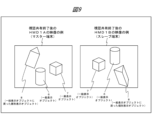
- FIG. 7 shows an image of the virtual space as seen from each terminal viewpoint at the time when visual sharing of the selected virtual object begins.
- Visual sharing here refers to a method of controlling the image display for a selected virtual object so that each user visually views the same orientation of the virtual object.
- a virtual object that is the subject of visual sharing may be referred to as an individual display object.
- a virtual object that is not an individual display object may be referred to as a general display object.
- virtual object 8 is designated as an individual display object, and virtual objects 6 and 7 are not designated as individual display objects, i.e., are general display objects. Therefore, in the following description, they may be referred to as "individual display object (virtual object 8).”
- the visibility of the individual display object is shared by, specifically, matching the appearance of the individual display object from the master terminal (HMD 1A in this case) with the appearance of the individual display object from the slave terminal (HMD 1B in this case).
- FIG. 8 is a diagram showing the state of the virtual space during visual sharing.
- the master terminal (HMD 1A) changes the position or orientation of the individual display object (virtual object 8)
- the display of the individual display object (virtual object 8) on the slave terminal (HMD 1B) changes accordingly. Therefore, the appearance of virtual object 8, which is an individual display object, is synchronized and appears the same on the slave terminal (HMD 1B) and the master terminal (HMD 1A).
- the appearance of virtual objects 6 and 7, which are general display objects is different on the master terminal (HMD 1A) and the slave terminal (HMD 1B) because they are displayed as seen from the viewpoint of the slave terminal (HMD 1B).
- the display 119B displays an image in which an individual display object 8 using an image from the viewpoint direction of the master terminal (HMD1A) is arranged on the background of the virtual space using an image from the viewpoint position of the slave terminal (HMD1B), and general display objects 6 and 7 using an image from the viewpoint direction of the slave terminal (HMD1B) are arranged.
- FIG. 9 is a diagram showing an example of the state of the virtual space after visual sharing has ended.
- the individual display object (virtual object 8) returns to a general display object, but the position and orientation of the general display object at that time are the final position and orientation of the individual display object (virtual object 8) for the master terminal (HMD 1A).
- the master terminal (HMD 1A) the master terminal
- the slave terminal (HMD 1B) the general display object arranged in the virtual space is displayed in a state that is visible from the terminal viewpoint of the slave terminal (HMD 1B) in the same way as other general display objects.
- a method of returning to the state immediately before visual sharing began may be used.
- the master terminal (HMD1A) and the slave terminal (HMD1B) are not fixed, and their roles can be swapped as appropriate.
- Fig. 10 is a diagram showing a definition coordinate system of an individual display object
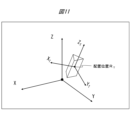
- Fig. 11 is a diagram showing the position and orientation of a virtual object definition coordinate system with respect to a virtual space coordinate system.
- the rendering of this virtual object in the virtual space can be executed by determining the position of the virtual object origin O T in the virtual space (hereinafter sometimes referred to as the "placement position R T ”) and the orientation in the virtual space of the virtual object definition coordinate system ⁇ X T , Y T , Z T ⁇ (hereinafter sometimes referred to as the "placement orientation") in the virtual space coordinate system ⁇ X, Y, Z ⁇ shown in Fig. 11 (Fig. 11).
- the "orientation in the virtual space” refers to the orientation of the virtual object definition coordinate system ⁇ X T , Y T , Z T ⁇ with respect to the virtual space coordinate system ⁇ X, Y, Z ⁇ .
- symbols that represent points in space, directions, and rotations in space are expressed as quaternions.
- quaternions that represent directions are normalized to a magnitude of 1.
- the real parts of quaternions that represent points and directions are set to 0.
- the conjugate quaternion of quaternion q is represented as q * .
- the orientation of the virtual object is represented by rotation QT , the virtual space coordinate system ⁇ X, Y, Z ⁇ , and the directions of each coordinate axis of the virtual space coordinate system ⁇ X, Y, Z ⁇ in the virtual space by Nx , Ny , and Nz .
- rotation QT the directions of each coordinate axis of the virtual object definition coordinate system ⁇ XT , YT , ZT ⁇ in the virtual space.
- the position and orientation at which the virtual object is displayed can be specified.
- the display state of a virtual object is expressed by a pair of a position and an orientation [R T , Q T ]. It is assumed that the coordinate system of the virtual space is shared between the master terminal (HMD 1A) and the slave terminal (HMD 1B), and that the position and orientation information of each virtual object is shared by communication between the master terminal (HMD 1A) and the slave terminal (HMD 1B) or by communication via the server 3.
- Fig. 12 is a diagram showing the positional relationship between the two terminal viewpoints and the virtual object as viewed from above in the state of Fig. 6.
- the display state of the virtual object 8 immediately before the start of visual sharing is set to [R T0 , Q T0 ].
- FIG. 13 is a diagram showing the positional relationship between the two terminal viewpoints and the virtual objects at the start of visual sharing in FIG. 7.
- the orientation of virtual object 8 which has become an individual display object, changes when visual sharing begins.
- FIG. 14 is a diagram showing the display reference arrangement in the master terminal at the start of visual sharing.
- FIG. 15 is a diagram showing the display reference arrangement in the slave terminal at the start of visual sharing.
- the positions and orientations of the individual display objects in the display reference arrangement are assumed to be the initial states of the arrangement positions and orientations of the individual display objects in each mobile information terminal, i.e., the master terminal (HMD1A) and the slave terminal (HMD1B), at the start of visual sharing in FIG. 13.
- an individual display object viewed from the master terminal (HMD 1A) is located at the initial arrangement position R T0 of the individual display object.
- an individual display object viewed from the slave terminal (HMD 1B) is located at the initial arrangement position R T0 of the individual display object.
- a horizontal reference direction for the individual display object (virtual object 8) is set.
- a point projected in the vertical direction from the terminal reference point onto a horizontal plane including the initial arrangement position R_T0 of the individual display object is set as a projection point, and a direction from the initial arrangement position R_T0 of the individual display object toward the projection point is set as a horizontal reference direction.
- the horizontal reference direction of the master terminal (HMD 1A) is denoted as D (M) H0
- the horizontal reference direction of the slave terminal (HMD 1B) is denoted as D (S) H0 .
- the current arrangement position of the individual display object (virtual object 8) during visual sharing is R (#) T
- the arrangement orientation is Q (#) T
- the superscript (#) indicates the distinction between master and slave, with (M) meaning the master and (S) meaning the slave.
- the arrangement position change amount and the arrangement orientation are rotated by the amount of the difference in the horizontal reference direction.
- Figure 16 shows the relationship between the horizontal reference direction of the master terminal and the horizontal reference direction of the slave terminal.
- the arrangement position R (M) T and arrangement orientation Q (M) T are transformed by a transformation that rotates the horizontal reference direction D (M) H0 around the vertical axis until it overlaps with the horizontal reference direction D (S) H0 .
- This makes it possible to display the individual display object (virtual object 8) on the slave terminal (HMD 1B) as if it were viewed from the direction in which the master terminal (HMD 1A) is located.
- the rotation representing this transformation is called MS rotation transformation and the rotation transformation parameter is represented as Q (MS) V
- Q (MS) V can be written as follows:
- Q (MS) V cos ( ⁇ /2) + sin ( ⁇ /2) N V ... (4)
- N V is a quaternion representation of a unit vector in the vertically upward direction
- ⁇ is the angle, measured clockwise when facing the vertically upward direction, from the horizontal reference direction D (M) H0 of the master terminal to the horizontal reference direction D (S) H0 of the slave terminal (HMD 1B) in the display reference arrangement.
- i, j, and k are basis elements of the quaternion other than 1. In the case of complex numbers, there is only one i.
- the slave terminal (HMD 1B) can display the individual display object (virtual object 8) in the same state as seen from the master terminal (HMD 1A) in terms of its orientation in the horizontal plane.
- the initial setting information that the slave terminal (HMD1B) should acquire is information (R T0 ) of the terminal reference point of the master terminal (HMD1A) and the initial placement position of the individual display object (virtual object 8).
- the slave terminal (HMD1B) knows its own terminal reference point.
- R T0 is known, so information on R T0 is not necessary.
- D (M) H0 is obtained from the terminal reference point of the master terminal (HMD1A) and R T0
- D (S) H0 is obtained from the terminal reference point of the slave terminal (HMD1B) and R T0 .
- the display state of an individual display object may be changed by enlarging or reducing the virtual object.
- the way the virtual object is viewed from the master device remains the same as when a normal general display object is viewed, since it is displayed as it is from the viewpoint of the master device.
- the individual display object is displayed on the slave terminal so as to be seen from the viewpoint of the master terminal, but the display mode may be changed to the way it is seen from the position of the own terminal.
- the master terminal has the authority to change the position and orientation of the object, but the MS rotation transformation is not applied to the display on the slave terminal, and the object is displayed like a general object.
- the following equation is used instead of equations (5) and (6).
- R (S) T R (M) T ...(7)
- Q (S) T Q (M) T ...(8)
- the display from the perspective of the master terminal (equations (5) and (6)) will be called the MS conversion display, and the display from the perspective of the slave terminal (equations (7) and (8)) will be called the normal display.
- the method of viewing from the viewpoint of another terminal can be applied to terminals other than the master terminal.
- a rotation transformation corresponding to the MS rotation transformation can be obtained from the terminal reference point of the other terminal and the placement position of the target object, so a similar display mode transformation is possible.
- the horizontal reference direction D (M) H0 is replaced with that of the other terminal with which you want to share visibility. This is useful when you want to temporarily check how it looks from another terminal.
- the master terminal When visual sharing begins, the master terminal is first determined. If a certain user is the main presenter throughout a given situation, such as a conference, then that user is considered to be the default master terminal for that situation. Alternatively, a mobile information terminal that wishes to become the master terminal may declare itself to be the master terminal and become the master terminal. If other slave terminals wish to share visual sharing with the master terminal, they start visual sharing by specifying the target general display object.
- the method of specifying a virtual object can be any method, such as pointing with a beam from a controller, specifying with a virtual object representing the user's hand, gazing with the line of sight, or selecting a number assigned to each virtual object.
- Figure 17 shows an example of a master terminal display.
- a graphical display indicating that the user is the master terminal user may be added to the avatar corresponding to the user of the master terminal.
- a master terminal mark MRK_M may be added to the avatar AVT_A, or a master terminal display MSG_MA including a text display may be added.
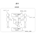
- Figure 18 shows another example of the master terminal display.
- a master terminal may be set for each specific virtual object. In other words, if there are multiple virtual objects in the virtual space, the master terminal for each virtual object may be different.
- the master terminal for virtual object 8 is HMD 1A, so a master terminal display MSG_MA stating "Master terminal is Person A" is added to virtual object 8.
- the slave terminal for virtual object 8 is HMD 1B.
- the master terminal of virtual object 7 is HMD 1B, so a master terminal display MSG_MB saying "Master terminal is person B" is added to virtual object 7.
- the slave terminal of virtual object 7 is HMD 1A.
- virtual object 6 is a general display object.
- the viewing and sharing of individual display objects may be performed among three or more mobile information terminals.
- one mobile information terminal becomes the master terminal and the other mobile information terminals become slave terminals.
- the slave terminal may be temporarily delegated the authority of the master terminal, allowing it to change the position and orientation of individual display objects. If the master terminal becomes a slave terminal midway through, it obtains terminal reference point information of the mobile information terminal that will become the new master terminal, and calculates a rotation transformation that converts the orientation information.
- other mobile information terminals may later join as slave terminals to a group that is sharing visibility. If initial setting information is acquired at the time of joining, the display state to be displayed on the mobile information terminal itself can be determined from the display state of the individual display object on the subsequent master terminal. This initial setting information may be received directly from the master terminal, or from another slave terminal or the server 3.
- each virtual object may have a different master terminal.
- each mobile information terminal transmits initial setting information of each mobile information terminal to the server 3.
- the initial setting information is information on the terminal reference position of each mobile information terminal and the initial placement position of the individual display object at the time when it becomes the master terminal.
- the mobile information terminal that has become the master terminal transmits change information by the master terminal on the display state of the individual display object to the server 3.
- the server 3 performs display control of the individual display object of each mobile information terminal.
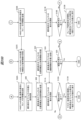
- FIG. 19 is a flowchart showing the process flow of the video sharing system according to this embodiment, and shows how the display of an individual display object is controlled on a mobile information terminal.
- the following describes an example of a process in which one of three virtual objects is designated as an individual display object between user A and user B as shown in FIG. 1 and displayed.
- the HMD 1A accepts the setting process as the master terminal. Also in this step, the HMD 1A accepts the designation of an individual display object (S02A). With this process, the HMD 1A notifies the HMD 1B that it has become the master terminal. Upon receiving this notification, the HMD 1B sets itself up as a slave terminal (S02B).
- the master terminal (HMD1A) transmits the initial setting information to the slave terminal (HMD1B) (S03), which is received by the slave terminal (HMD1B) (S04).
- the initial setting information includes the terminal reference point information of the master terminal (HMD1A).
- the initial setting information also includes information indicating which of the virtual objects the individual display object is, and information indicating its initial placement position.
- the slave terminal (HMD 1B) determines MS rotation transformation parameters Q (MS) V for transforming the display state using the master terminal (HMD 1A ) reference point information in the received initial setting information and the terminal reference point information of its own portable information terminal (S05).
- the display mode is set in the HMD 1B (S06).
- the display mode here includes display from the master terminal viewpoint using MS rotation transformation (equations (5) and (6)) and normal display (equations (7) and (8)).
- HMD1A and HMD1B The position and orientation of each device is measured for HMD1A and HMD1B (S07A, S07B).
- the master terminal changes the display state of an individual display object, i.e., when it changes either the position or the orientation of the individual display object, or both (S08)
- the change information is transmitted from HMD1A to the slave terminal (HMD1B) (S09), and is received by the slave terminal (HMD1B) (S10).
- the slave terminal (HMD1B) updates the display of the individual display objects in response to changes in the position and orientation of the master terminal (HMD1A) and in the display state of the individual display objects (S11). This makes it possible to display the virtual object 8 seen from the viewpoint of HMD1A on the display 119B of HMD1B, so that user A and user B can view the same virtual object from the same viewpoint. In other words, user A and user B can share a viewpoint.
- the method of returning the individual display object (virtual object 8) to the display of a general display object may be to return it to the display state immediately before visual sharing began, or to the display state in the master terminal (HMD 1A) at the time visual sharing ends.
- the method of return may be set as a default value for the visual sharing method, or may be switched in response to a selection from user A of the master terminal (HMD 1A) at the time visual sharing ends.
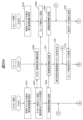
- FIGS. 20A and 20B are flowcharts showing the process flow of the video sharing system according to this embodiment, and show how the server controls the display of individual display objects.
- the server receives information for conversion and controls the display, but since the process is basically the same as in FIG. 19, the same step numbers are used for steps that are common to FIG. 19.
- the HMD 1A accepts the setting process as the master terminal. Also in this step, the HMD 1A accepts the designation of individual display objects. At the same time, the master terminal (HMD 1A) notifies the server 3 and HMD 1B that it has become the master terminal, and the server 3 and HMD 1B receive the notification (S02A, S02S, S02B).
- the master terminal (HMD1A) and the slave terminal (HMD1B) each transmit initial setting information to the server (S03A, S30B), which is received by the server 3 (S04).
- the server 3 obtains a rotation transformation parameter Q (MS) V of the display state using the master terminal (HMD 1A) reference point information and the slave terminal (HMD 1B) terminal reference point information in the received initial setting information (S05).
- the slave terminal sets the display mode to either its own terminal's viewpoint or the master terminal's viewpoint, and transmits this to the server 3 (S30).
- the server 3 receives this display mode setting information (S31).
- HMD1A and HMD1B each measure the position and orientation of the device and transmit the measurements to server 3 (S22A, S22B), which then receives them (S22S).
- the master terminal (HMD 1A) changes either the position or the orientation, or both, of the individual display object (S08)
- information on the change is transmitted from HMD 1A to the server 3 (S09), and is received by the server 3 (S23).
- the server 3 calculates drawing information of the individual object for each terminal from the positions and orientations of the master terminal (HMD 1A) and the slave terminal (1B) and the changes in the positions and orientations of the individual display objects, and transmits the drawing information to the master terminal (HMD 1A) and the slave terminal (HMD 1B) (S24).
- the master terminal (HMD 1A) and the slave terminal (HMD 1B) update the display of the individual display objects using the drawing information received from the server 3 (S11A, S11B). This makes it possible to display the virtual object 8 seen from the viewpoint of HMD 1A on the display 119B of HMD 1B, so that user A and user B can see the same virtual object from the same viewpoint. In other words, user A and user B can share the same viewpoint.
- a virtual object seen from the viewpoint of the master terminal can be seen from the slave terminal, so the user of the master terminal and the user of the slave terminal can share the same view of the virtual object even if they are in different positions or facing different directions. This is expected to lead to improved understanding and smoother communication by sharing the view of a virtual object between different users, for example, in support of work, surgery, learning, education, etc.
- the authority to change the display state of the individual display object (hereinafter referred to as individual display change authority) may be transferred between terminals instead of being fixed to the master terminal (HMD 1A).
- individual display change authority may be transferred between terminals instead of being fixed to the master terminal (HMD 1A).
- the individual display change authority may be automatically transferred to the terminal that changed the display state of the individual object without issuing an instruction to transfer the authority. If there are terminals that attempt to change the display at almost the same time, the authority is transferred to the terminal that made the display change first. To avoid conflicting operations and confusion, once the authority is transferred, the individual display change authority may remain on that terminal for a certain period of time after the operation on that terminal is terminated.
- S is a symbol used to represent the slave terminals (HMD1B), including the master terminal (HMD1A) that has temporarily become the slave terminal (HMD1B), and that the value of ⁇ 1 differs for each terminal.
- this rotation transformation parameter Q (M1S) V the display state [R (M1) T , Q (M1) T ] of the individual display object (virtual object 8) in the temporary master terminal (HMD1A) can be transformed into the display state in another slave terminal (HMD1B), just like in the basic form.
- FIG. 21 is a diagram showing a display example according to the third modification of the first embodiment.
- the user when a user does not have the authority to change the position or orientation of an individual display object (virtual object 8), the user can temporarily view the individual display object (virtual object 8) from a direction that the user wishes to view.
- This method may also be used for general display objects.
- the virtual object can be temporarily viewed from the direction the user wishes to view it without affecting how it appears to other users.
- the display of the individual display object (virtual object 8) or general display object in a state where no changes have been made on the user's own mobile information terminal may be completely erased, or may be displayed in a different display mode, such as being displayed dimmed.
- the virtual object in a display state where changes have been made on the user's own mobile information terminal may be displayed in a different display mode, such as being displayed dimmed.
- FIG. 22 is a diagram showing a display example according to the fourth modification of the first embodiment.
- a method of individual display is used to realize that each terminal can view the virtual object of interest in the same way.
- a method in which each terminal views the virtual space from a reference display direction set for the entire virtual space, that is, the terminal viewpoint position is set to the same position, thereby realizing visual sharing.
- the avatars of each user are displayed, the avatars are displayed overlapping each other.
- FIG. 23 is a diagram showing a display example according to the second embodiment.
- the master avatar is, for example, the avatar of a central figure, such as the person at the center of the discussion or the person giving the explanation.
- the terminal corresponding to the master avatar is the master terminal (HMD1A).
- the slave terminals (HMD1B) other than the master terminal (HMD1A) use the terminal viewpoint of the master terminal (HMD1A) as a shared viewpoint.
- the user's avatar (hands, etc.) seen on the slave device (HMD1B) may be that of the master avatar, or the user's own avatar may be displayed after adjusting the height. Being able to see one's own body or a substitute for it provides a sense of stability without the feeling of floating in the air. Alternatively, if the movements of the master avatar differ from one's own and cause discomfort, the avatar may be made invisible.
- the slave avatar that was in the original position corresponding to the slave terminal may stop displaying while visual sharing is in progress, or may return to its original position after visual sharing is complete, and may be displayed in its original position in a form that indicates that visual sharing is in progress, for example as a semi-transparent, light-colored object.
- the authority to change the position and orientation of the virtual object may be limited to the master terminal (HMD1A).
- the audio of a slave avatar engaged in line-of-sight sharing may be emitted from the line-of-sight sharing location to indicate that it is in the line-of-sight sharing location, or it may be emitted from the original avatar's location to make it easier to tell who is speaking.
- the avatar When entering a shared view location, the avatar may walk there so that the change in position is visible. Alternatively, to save time, the avatar may move to the shared view location instantly.
- the viewpoint of the master terminal and the viewpoint of the slave terminal can be shared. Furthermore, it is expected that the user of the slave terminal will be able to easily grasp the positional relationship between the viewpoint of the master terminal and the virtual object.
- FIG. 24 is a diagram showing a display example according to the first modification of the second embodiment.
- the height of the viewpoint of each terminal is not constant, so when a slave terminal (HMD1B) at a different height from the viewpoint of the master terminal (HMD1A) performs visual sharing, an awkward feeling will occur if the viewpoint of the master terminal (HMD1A) is used. For this reason, a vertical line passing through the viewpoint position of the master terminal (HMD1A) is drawn and defined as the shared viewpoint line. Then, when the slave terminal (HMD1B) performs visual sharing, the position at the height of the terminal viewpoint of its own mobile information terminal on the shared viewpoint line is used as the viewpoint during visual sharing. This will eliminate the awkward feeling described above.
- the viewpoint of the master terminal and the viewpoint of the slave terminal can be shared, similar to the effect of the second embodiment described above. Furthermore, it is expected that the user of the slave terminal will be able to easily grasp the positional relationship between the viewpoint of the master terminal and the virtual object.
- FIG. 25 is a diagram showing a display example according to the second modification of the second embodiment.
- the master avatar may be switched.
- HMD 1A becomes the master terminal
- HMD 1B becomes the new master terminal
- the master avatar corresponding to user B of HMD 1B may be displayed in the same position.
- visual sharing may be performed at the viewpoint position of the master avatar when HMD 1B was the slave terminal, or as in the first embodiment, visual sharing may be performed only for the target individual display object (virtual object 8) at the original position of the mobile information terminal itself.
- the target individual display object virtual object 8
- HMD 1B finishes speaking, it may remain at the position of the master avatar, or it may return to its original position.
- the viewpoint of the master terminal and the viewpoint of the slave terminal can be shared, similar to the effect of the second embodiment described above. Furthermore, it is expected that the user of the slave terminal will be able to intuitively understand that the viewpoint is shared with the master terminal.
- FIG. 26 is a diagram showing a display example according to the third modification of the second embodiment.
- slave avatars that share visibility may be displayed side-by-side behind the master avatar.
- the viewpoint of the master terminal and the viewpoint of the slave terminal can be shared, similar to the effect of the second embodiment described above. Furthermore, it is expected that the effect will be that it will be easier for each user of the master terminal and the slave terminal to intuitively grasp who is in the position of the shared viewpoint.
- FIG. 27 is a diagram showing a display example according to the fourth modification of the second embodiment.
- the avatar to be shared visually may be displayed in a reduced size at the shared visual location.
- the viewpoint of the master terminal and the viewpoint of the slave terminal can be shared, similar to the effect of the second embodiment described above. Furthermore, the display area of the avatar can be made smaller, making it easier to secure the display area for the virtual object.
- the master avatar can be made to stand out by either being the original size or scaled smaller than the slave avatar.
- FIG. 28 is a diagram showing a display example according to the fifth modification of the second embodiment.
- an avatar may be used that is shared among multiple mobile information terminals.
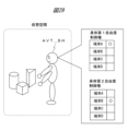
- the mobile information terminals using this shared avatar AVT_SH can share the view.
- the avatar's body can be controlled only by one of the mobile information terminals. Since allowing voice output from too many mobile information terminals can cause confusion, voice output rights may be restricted to a few terminals.
- the appearance of the shared avatar AVT_SH may be different from the appearance of other single-use avatars to distinguish it from single-use avatars.
- FIG. 29 is a diagram showing a display example according to the sixth modification of the second embodiment.
- the degree of freedom of the body can be increased by, for example, increasing the number of arms, moving away from the normal human appearance, and joint control from multiple terminals can be performed.
- Figure 29 shows the case where the number of arms is increased.
- the avatar's physical degrees of freedom are divided, and each mobile information device has control over each degree of freedom.
- the normal body part is the first degree of freedom
- the added lower arm part is the second degree of freedom.
- restrictions can be placed on the control of the first degree of freedom, such as limiting the movement of the torso part to a certain speed or less, including when it is stationary.
- the lower arm may be completely decoupled from the first degree of freedom of movement.
- the target body part of the first degree of freedom e.g. the upper arm
- the target body part of the second degree of freedom e.g. the lower arm
- multiple mobile information terminals are connected for communication, and the user can see the virtual object as it appears from the viewpoint of another user.
- the user can experience a shared view with other mobile information terminal users.
- each processing example may be independent programs, or multiple programs may constitute a single application program. Furthermore, the order in which each process is performed may be changed.
- each function may be realized in part or in whole by a server.
- the server may be any type of server as long as it can execute functions in cooperation with other components via communication, such as a local server, cloud server, edge server, or net service.
- Information such as programs, tables, and files that realize each function may be stored in a memory, a recording device such as a hard disk or SSD (Solid State Drive), or a recording medium such as an IC card, SD card, or DVD, or may be stored in a device on a communication network.
- a recording device such as a hard disk or SSD (Solid State Drive), or a recording medium such as an IC card, SD card, or DVD, or may be stored in a device on a communication network.
- control lines and information lines shown in the diagram are those considered necessary for explanation, and do not necessarily represent all control lines and information lines on the product. In reality, it can be assumed that almost all components are interconnected.
- a video sharing system A first portable information terminal; A second portable information terminal, The first portable information terminal is A first display; A first communication device that transmits and receives data to and from the second portable information terminal; a first processor that controls the first display and the first communication device; Equipped with The first processor, execute visual sharing control to switch a display mode of an individual display object consisting of a virtual object to be a visually shared target from an image from a viewpoint position of the first portable information terminal to an image from a viewpoint direction of the second portable information terminal based on the data received via the first communication device, in accordance with a selection operation by a user of the first portable information terminal or a user of the second portable information terminal; the first display displays the individual display object using an image from a viewpoint direction of the second portable information terminal; Video sharing system.
- a video sharing method comprising: A step of executing visual sharing control by the portable information terminal to switch a display mode of a virtual object selected as a visual sharing target among a plurality of users from an image from a viewpoint position of the portable information terminal to an image from a viewpoint direction of another portable information terminal; and displaying the virtual object by the mobile information terminal using an image from a viewpoint direction of the other mobile information terminal. How to share video.
- HMD 1B HMD 1C: Smartphone 1D: Smartphone 3: Server 5: Independent display object 6: Virtual object 7: Virtual object 8: Virtual object 9: Network 23A: Access point 23B: Access point 100: Video sharing system 111A: Out camera 111B: Out camera 113A: Distance measurement sensor 113B: Distance measurement sensor 114A: RTC 114B: RTC 115A: acceleration sensor 115B: acceleration sensor 116A: gyro sensor 116B: gyro sensor 117A: geomagnetic sensor 117B: geomagnetic sensor 118A: positioning sensor 118B: positioning sensor 119A: display 119B: display 120A: network communication device 120B: network communication device 121A: microphone 121B: microphone 122A: speaker 122B: speaker 123A: antenna 123B: antenna 125A: processor 125B: processor 126A: program 126B: program 127A: data 127B: data 128A: memory 128B: memory 129A: wireless communication device
Landscapes
- Engineering & Computer Science (AREA)
- Multimedia (AREA)
- Signal Processing (AREA)
- Social Psychology (AREA)
- General Health & Medical Sciences (AREA)
- Health & Medical Sciences (AREA)
- General Engineering & Computer Science (AREA)
- Computer Networks & Wireless Communication (AREA)
- Databases & Information Systems (AREA)
- Information Transfer Between Computers (AREA)
- Telephonic Communication Services (AREA)
- User Interface Of Digital Computer (AREA)
- Processing Or Creating Images (AREA)
Priority Applications (4)
| Application Number | Priority Date | Filing Date | Title |
|---|---|---|---|
| JP2025516456A JPWO2024224608A1 (https=) | 2023-04-28 | 2023-04-28 | |
| EP23935384.0A EP4704426A1 (en) | 2023-04-28 | 2023-04-28 | Video sharing system and video sharing method |
| CN202380097607.3A CN121002889A (zh) | 2023-04-28 | 2023-04-28 | 影像共享系统和影像共享方法 |
| PCT/JP2023/016895 WO2024224608A1 (ja) | 2023-04-28 | 2023-04-28 | 映像共有システム及び映像共有方法 |
Applications Claiming Priority (1)
| Application Number | Priority Date | Filing Date | Title |
|---|---|---|---|
| PCT/JP2023/016895 WO2024224608A1 (ja) | 2023-04-28 | 2023-04-28 | 映像共有システム及び映像共有方法 |
Publications (1)
| Publication Number | Publication Date |
|---|---|
| WO2024224608A1 true WO2024224608A1 (ja) | 2024-10-31 |
Family
ID=93255795
Family Applications (1)
| Application Number | Title | Priority Date | Filing Date |
|---|---|---|---|
| PCT/JP2023/016895 Ceased WO2024224608A1 (ja) | 2023-04-28 | 2023-04-28 | 映像共有システム及び映像共有方法 |
Country Status (4)
| Country | Link |
|---|---|
| EP (1) | EP4704426A1 (https=) |
| JP (1) | JPWO2024224608A1 (https=) |
| CN (1) | CN121002889A (https=) |
| WO (1) | WO2024224608A1 (https=) |
Citations (5)
| Publication number | Priority date | Publication date | Assignee | Title |
|---|---|---|---|---|
| JPH0981782A (ja) * | 1995-07-12 | 1997-03-28 | Sony Corp | 3次元仮想現実空間共有方法、3次元仮想現実空間共有システム、情報記録媒体、情報記録方法、情報伝送媒体、情報伝送方法、情報処理方法、クライアント端末、並びに共有サーバ端末 |
| JP2001022958A (ja) | 1999-07-06 | 2001-01-26 | Nippon Telegr & Teleph Corp <Ntt> | 仮想空間システムにおけるオブジェクト表示方法およびオブジェクト表示プログラムを記録した記録媒体 |
| JP2015163968A (ja) * | 2008-07-10 | 2015-09-10 | リアル ビュー イメージング リミテッド | 広視野角ディスプレイおよびユーザインタフェース |
| US20170053445A1 (en) * | 2015-08-20 | 2017-02-23 | Microsoft Technology Licensing, Llc | Augmented Reality |
| JP2017120650A (ja) * | 2014-09-30 | 2017-07-06 | キヤノンマーケティングジャパン株式会社 | 情報処理システム、その制御方法、及びプログラム、並びに情報処理装置、その制御方法、及びプログラム |
Family Cites Families (1)
| Publication number | Priority date | Publication date | Assignee | Title |
|---|---|---|---|---|
| CN114127794A (zh) | 2019-09-20 | 2022-03-01 | 麦克赛尔株式会社 | 信息终端装置以及位置辨识共享方法 |
-
2023
- 2023-04-28 CN CN202380097607.3A patent/CN121002889A/zh active Pending
- 2023-04-28 JP JP2025516456A patent/JPWO2024224608A1/ja active Pending
- 2023-04-28 WO PCT/JP2023/016895 patent/WO2024224608A1/ja not_active Ceased
- 2023-04-28 EP EP23935384.0A patent/EP4704426A1/en active Pending
Patent Citations (5)
| Publication number | Priority date | Publication date | Assignee | Title |
|---|---|---|---|---|
| JPH0981782A (ja) * | 1995-07-12 | 1997-03-28 | Sony Corp | 3次元仮想現実空間共有方法、3次元仮想現実空間共有システム、情報記録媒体、情報記録方法、情報伝送媒体、情報伝送方法、情報処理方法、クライアント端末、並びに共有サーバ端末 |
| JP2001022958A (ja) | 1999-07-06 | 2001-01-26 | Nippon Telegr & Teleph Corp <Ntt> | 仮想空間システムにおけるオブジェクト表示方法およびオブジェクト表示プログラムを記録した記録媒体 |
| JP2015163968A (ja) * | 2008-07-10 | 2015-09-10 | リアル ビュー イメージング リミテッド | 広視野角ディスプレイおよびユーザインタフェース |
| JP2017120650A (ja) * | 2014-09-30 | 2017-07-06 | キヤノンマーケティングジャパン株式会社 | 情報処理システム、その制御方法、及びプログラム、並びに情報処理装置、その制御方法、及びプログラム |
| US20170053445A1 (en) * | 2015-08-20 | 2017-02-23 | Microsoft Technology Licensing, Llc | Augmented Reality |
Non-Patent Citations (1)
| Title |
|---|
| See also references of EP4704426A1 |
Also Published As
| Publication number | Publication date |
|---|---|
| JPWO2024224608A1 (https=) | 2024-10-31 |
| CN121002889A (zh) | 2025-11-21 |
| EP4704426A1 (en) | 2026-03-04 |
Similar Documents
| Publication | Publication Date | Title |
|---|---|---|
| US9858643B2 (en) | Image generating device, image generating method, and program | |
| JP7428843B2 (ja) | 情報端末装置および位置認識方法 | |
| JP7821251B2 (ja) | 表示装置 | |
| CN110022363B (zh) | 虚拟对象的运动状态修正方法、装置、设备及存储介质 | |
| JP2019062534A (ja) | 通信端末、画像通信システム、表示方法、及びプログラム | |
| JP7274510B2 (ja) | 仮想オブジェクト表示装置及び仮想オブジェクト表示方法 | |
| JPWO2017134886A1 (ja) | 情報処理装置、情報処理方法、及び記録媒体 | |
| JP7502346B2 (ja) | 空間認識システム、情報端末、および空間認識方法 | |
| JP2009157526A (ja) | 画像処理システム、画像処理システムの制御方法及びコンピュータプログラム | |
| WO2019106862A1 (ja) | 操作案内システム | |
| WO2024224608A1 (ja) | 映像共有システム及び映像共有方法 | |
| JP5802019B2 (ja) | 情報処理装置、情報処理プログラム、情報処理方法、情報処理システム | |
| JP6091476B2 (ja) | 設備機器操作装置、設備機器操作方法およびプログラム | |
| JP2018067157A (ja) | 通信装置およびその制御方法 | |
| CN114245755B (zh) | 信息处理装置、信息处理方法和记录介质 | |
| US20250371827A1 (en) | Information processing device, program, and information processing system | |
| WO2018042658A1 (ja) | 携帯情報端末、頭部装着表示システム、及びその音声出力制御方法 | |
| JP5525924B2 (ja) | 立体画像表示プログラム、立体画像表示装置、立体画像表示システム、および、立体画像表示方法 | |
| JP7525515B2 (ja) | 空間認識システム、空間認識方法、および情報端末 | |
| WO2024201814A1 (ja) | 映像共有システム及び映像共有方法 | |
| CN114201028A (zh) | 扩增实境系统与其锚定显示虚拟对象的方法 | |
| JP5546960B2 (ja) | 立体画像表示プログラム、立体画像表示装置、立体画像表示システム、および、立体画像表示方法 | |
| WO2022172335A1 (ja) | 仮想ガイド表示装置、仮想ガイド表示システム、及び仮想ガイド表示方法 | |
| JP5541973B2 (ja) | 立体画像表示プログラム、立体画像表示装置、立体画像表示システム、および、立体画像表示方法 | |
| JP2025036084A (ja) | システム、方法、プログラム及び表示装置 |
Legal Events
| Date | Code | Title | Description |
|---|---|---|---|
| 121 | Ep: the epo has been informed by wipo that ep was designated in this application |
Ref document number: 23935384 Country of ref document: EP Kind code of ref document: A1 |
|
| ENP | Entry into the national phase |
Ref document number: 2025516456 Country of ref document: JP Kind code of ref document: A |
|
| WWE | Wipo information: entry into national phase |
Ref document number: 2025516456 Country of ref document: JP |
|
| WWE | Wipo information: entry into national phase |
Ref document number: 2023935384 Country of ref document: EP |
|
| NENP | Non-entry into the national phase |
Ref country code: DE |
|
| ENP | Entry into the national phase |
Ref document number: 2023935384 Country of ref document: EP Effective date: 20251128 |
|
| ENP | Entry into the national phase |
Ref document number: 2023935384 Country of ref document: EP Effective date: 20251128 |
|
| ENP | Entry into the national phase |
Ref document number: 2023935384 Country of ref document: EP Effective date: 20251128 |
|
| ENP | Entry into the national phase |
Ref document number: 2023935384 Country of ref document: EP Effective date: 20251128 |
|
| ENP | Entry into the national phase |
Ref document number: 2023935384 Country of ref document: EP Effective date: 20251128 |
|
| ENP | Entry into the national phase |
Ref document number: 2023935384 Country of ref document: EP Effective date: 20251128 |
|
| ENP | Entry into the national phase |
Ref document number: 2023935384 Country of ref document: EP Effective date: 20251128 |
|
| ENP | Entry into the national phase |
Ref document number: 2023935384 Country of ref document: EP Effective date: 20251128 |
|
| ENP | Entry into the national phase |
Ref document number: 2023935384 Country of ref document: EP Effective date: 20251128 |
|
| WWP | Wipo information: published in national office |
Ref document number: 2023935384 Country of ref document: EP |