WO2024219090A1 - 車載装置、プログラム、及び情報処理方法 - Google Patents
車載装置、プログラム、及び情報処理方法 Download PDFInfo
- Publication number
- WO2024219090A1 WO2024219090A1 PCT/JP2024/007395 JP2024007395W WO2024219090A1 WO 2024219090 A1 WO2024219090 A1 WO 2024219090A1 JP 2024007395 W JP2024007395 W JP 2024007395W WO 2024219090 A1 WO2024219090 A1 WO 2024219090A1
- Authority
- WO
- WIPO (PCT)
- Prior art keywords
- ecu
- vehicle
- redundant
- ecus
- control unit
- Prior art date
- Legal status (The legal status is an assumption and is not a legal conclusion. Google has not performed a legal analysis and makes no representation as to the accuracy of the status listed.)
- Ceased
Links
Images





Classifications
-
- B—PERFORMING OPERATIONS; TRANSPORTING
- B60—VEHICLES IN GENERAL
- B60R—VEHICLES, VEHICLE FITTINGS, OR VEHICLE PARTS, NOT OTHERWISE PROVIDED FOR
- B60R16/00—Electric or fluid circuits specially adapted for vehicles and not otherwise provided for; Arrangement of elements of electric or fluid circuits specially adapted for vehicles and not otherwise provided for
- B60R16/02—Electric or fluid circuits specially adapted for vehicles and not otherwise provided for; Arrangement of elements of electric or fluid circuits specially adapted for vehicles and not otherwise provided for electric constitutive elements
- B60R16/023—Electric or fluid circuits specially adapted for vehicles and not otherwise provided for; Arrangement of elements of electric or fluid circuits specially adapted for vehicles and not otherwise provided for electric constitutive elements for transmission of signals between vehicle parts or subsystems
-
- G—PHYSICS
- G06—COMPUTING OR CALCULATING; COUNTING
- G06F—ELECTRIC DIGITAL DATA PROCESSING
- G06F11/00—Error detection; Error correction; Monitoring
- G06F11/07—Responding to the occurrence of a fault, e.g. fault tolerance
- G06F11/16—Error detection or correction of the data by redundancy in hardware
- G06F11/20—Error detection or correction of the data by redundancy in hardware using active fault-masking, e.g. by switching out faulty elements or by switching in spare elements
Definitions
- the present disclosure relates to an in-vehicle device, a program, and an information processing method.
- This application claims priority based on Japanese Application No. 2023-067872 filed on April 18, 2023, and incorporates by reference all of the contents of the above-mentioned Japanese application.
- Body ECU which is an on-board ECU that controls body-related devices such as the wiper drive device, interior and exterior lighting devices, door lock devices, and power windows (see, for example, Patent Document 1).
- the wiper drive device of Patent Document 1 includes an on-board ECU (body ECU) and is driven by a control program applied to the on-board ECU (electronic control unit).
- the in-vehicle device is mounted on a vehicle and communicatively connected to a plurality of in-vehicle ECUs, and includes a control unit that performs processing related to status management of the in-vehicle ECUs.
- the control unit acquires status data related to the status of the in-vehicle ECU from the in-vehicle ECU, and when it determines that the in-vehicle ECU is not operating normally based on the acquired status data, it identifies a redundant ECU to replace the in-vehicle ECU determined to be not operating normally, and performs processing for the redundant ECU to replace the in-vehicle ECU determined to be not operating normally.
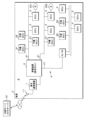
- FIG. 1 is a schematic diagram illustrating a system configuration of an in-vehicle system according to a first embodiment
- FIG. 2 is a block diagram illustrating an example of an internal configuration of an in-vehicle device (integrated ECU).
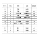
- FIG. 4 is an explanatory diagram illustrating an ECU state table
- FIG. 11 is an explanatory diagram illustrating an example of a substitution table.
- FIG. 11 is an explanatory diagram illustrating a relay table.
- FIG. 2 is an explanatory diagram illustrating a process flow (sequence) of an in-vehicle device and a redundant ECU, etc.
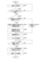
- 4 is a flowchart illustrating a process of a control unit of an in-vehicle device.
- FIG. 10 is a flowchart illustrating a process of a control unit of an in-vehicle device according to a second embodiment (specified based on a processing load); 13 is a flowchart illustrating a process of a control unit of an in-vehicle device according to a third embodiment (identification based on the number of possible substitutes); FIG. 13 is a schematic diagram illustrating a system configuration of an in-vehicle system according to a fourth embodiment (an integrated ECU including a redundant ECU).
- the on-board ECU installed in the vehicle of Patent Document 1 does not take into consideration the processing required to replace another on-board ECU when the other on-board ECU breaks down or ceases to operate normally.
- the present disclosure aims to provide an in-vehicle device etc. that can efficiently perform processing related to replacing an in-vehicle ECU when any of the in-vehicle ECUs installed in a vehicle stops functioning normally.
- An in-vehicle device is an in-vehicle device mounted on a vehicle and communicatively connected to a plurality of in-vehicle ECUs, and includes a control unit that performs processing related to status management of the in-vehicle ECUs.
- the control unit acquires status data related to the status of the in-vehicle ECU from the in-vehicle ECU, and when it determines that the in-vehicle ECU is not operating normally based on the acquired status data, it identifies a redundant ECU to replace the in-vehicle ECU determined to be not operating normally, and performs processing on the redundant ECU to replace the in-vehicle ECU determined to be not operating normally.
- the in-vehicle device is communicatively connected to a plurality of in-vehicle ECUs via an in-vehicle network mounted on the vehicle.
- These multiple in-vehicle ECUs perform processing for executing various services or functions provided in the vehicle.
- the in-vehicle ECUs may include not only the in-vehicle ECUs mounted at the time of production of the vehicle, but also in-vehicle ECUs (spare ECUs) mounted after production of the vehicle (retrofitting).
- the spare ECU may acquire a message output from an in-vehicle ECU (sensor/actuator control ECU) to which a sensor or actuator is directly connected via a signal line or the like, and perform processing for executing various services or functions using the acquired message.
- the control unit of the in-vehicle device collects information (state information) on the state of the in-vehicle ECUs including these spare ECUs, sensor/actuator control ECUs, and redundant system ECUs, i.e., information on whether the in-vehicle ECUs are in an operating state (wake-up state) or a stopped state (sleep state), and performs processing related to the current state management of the in-vehicle ECUs.
- the status information of the vehicle-mounted ECU may include management information regarding the functions performed by each vehicle-mounted ECU and whether or not the vehicle-mounted ECU is operating normally (normal or abnormal). Furthermore, the control unit of the vehicle-mounted device periodically, periodically, or steadily performs polling communication with the vehicle-mounted ECUs to acquire status data regarding the status of the vehicle-mounted ECUs. The control unit of the vehicle-mounted device determines that the vehicle-mounted ECU is not operating normally, for example, when the status data cannot be acquired beyond the transmission period, when the acquired status data includes an abnormality code indicating an abnormality in the vehicle-mounted ECU that is the transmission source, or when the acquired status data is determined to be fraudulent data due to, for example, spoofing.
- the case where the vehicle-mounted ECU is not operating normally includes, for example, when the vehicle-mounted ECU is broken or when the vehicle-mounted ECU is removed from the vehicle.
- the control unit of the vehicle-mounted device specifies a redundant ECU (substitute ECU) for replacing the vehicle-mounted ECU determined to be not operating normally.
- the redundant ECU is, for example, an in-vehicle ECU of the same type as the vehicle-mounted ECU determined to be not operating normally, or an in-vehicle ECU that is compatible with the vehicle-mounted ECU determined to be not operating normally.
- the redundant ECU can provide various services or functions that the vehicle ECU determines not to be operating normally by executing software that is the same as or compatible with the software executed by the vehicle ECU.
- the control unit of the vehicle device performs a process to substitute (substitute) the vehicle ECU determined not to be operating normally, such as a startup process such as sending a wake-up signal to the specified redundant ECU, or a command signal to start substitution (substitute start), etc.
- a startup process such as sending a wake-up signal to the specified redundant ECU, or a command signal to start substitution (substitute start), etc.
- the redundant ECU that receives the command from the vehicle device starts a process (substitution process) to substitute for the vehicle ECU determined not to be operating normally, so that the service or function performed by the vehicle ECU can be continued.
- the number of signal lines such as harnesses required for connecting the sensor or the like can be reduced.
- control unit acquires software executed by an in-vehicle ECU determined to be not operating normally, and outputs the acquired software to the redundant ECU, thereby performing processing to have the redundant ECU take the place of the ECU.
- the control unit of the in-vehicle device acquires software to be executed by the in-vehicle ECU that is determined not to be operating normally.
- the software may be acquired from an external server, such as an OTA (Over The Air) server located outside the vehicle.
- the software may be stored in advance in a storage area accessible by the control unit of the in-vehicle device, such as a storage unit of the in-vehicle device, and the software may be acquired by accessing the storage area.
- the control unit of the in-vehicle device transmits (outputs) the software acquired from, for example, an external server to the specified redundant ECU.
- the redundant ECU can acquire the software from the in-vehicle device and execute the acquired software by installing (applying) the acquired software, thereby efficiently performing the replacement process.
- the redundant ECU does not need to hold (store) the software of the in-vehicle ECU in advance, and the storage area of the redundant ECU can be prevented from becoming tight.
- the latest version of the software acquired from an external server can be applied to the redundant ECU.
- the status data acquired from the in-vehicle ECU includes setting information regarding the operational settings of the in-vehicle ECU at the time of transmitting the status data, and the control unit outputs the setting information to the redundant ECU, thereby performing processing to cause the redundant ECU to substitute.
- the status data output (transmitted) by the on-board ECU to the on-board device periodically, regularly, or steadily includes setting information related to the operational settings of the on-board ECU at the time of transmitting the status data.
- the on-board ECU provides services or functions by executing software, and the setting information corresponds to, for example, various setting information for providing the services or functions.
- the setting information may include, for example, user information related to the driver driving the vehicle, and may further include setting information associated with each piece of user information (setting information for each driver).
- the setting information may include history information such as the operation contents performed by the driver (current user) currently driving the vehicle when using a service, etc.
- the control unit of the on-board device outputs (transmits) to the redundant ECU, in addition to software required to replace the on-board ECU, setting information related to the operational settings of the on-board ECU at the time of transmitting the status data from the on-board ECU.
- the redundant ECU can execute the software by reflecting the setting information, and can continue to provide services or functions by inheriting the operational settings of the vehicle-mounted ECU that it is replacing.
- control unit uses a relay table stored in an accessible storage area to relay messages sent and received between the multiple in-vehicle ECUs, and changes the relay table depending on the identified redundant ECU.
- a relay table is stored in a storage area accessible to the control unit of the in-vehicle device, such as the storage unit of the in-vehicle device, and the control unit of the in-vehicle device refers to the relay table to relay messages transmitted and received between multiple in-vehicle ECUs.
- the in-vehicle device has multiple in-vehicle communication units corresponding to the physical layers of each communication protocol, such as a CAN transceiver or an Ether PHY unit, and functions as a relay device (CAN gateway, Ether switch) that relays messages transmitted and received by each of the in-vehicle ECUs connected to each of the multiple in-vehicle communication units.
- the redundant ECU replaces an in-vehicle ECU determined to be malfunctioning
- the address of the redundant ECU and the address of the in-vehicle ECU are different on the in-vehicle network.
- a message such as a CAN
- the in-vehicle ECU to be relayed is specified according to the identifier (message ID) of the message, it is assumed that it will be necessary to change the relay destination from the in-vehicle ECU determined to be malfunctioning to the redundant ECU.
- the control unit of the in-vehicle device changes the relay table according to the identified redundant ECU, so it can reliably relay messages and the like required to execute a service or function to the redundant ECU instead of the in-vehicle ECU to be substituted.
- a replacement table relating to replacement by each of the multiple redundant ECUs is stored in a storage area accessible to the control unit, and the control unit identifies one of the multiple redundant ECUs by referring to the replacement table.
- the vehicle is equipped with multiple redundant ECUs.
- These redundant ECUs may be configured with spare ECUs that are retrofitted to the vehicle in order to add new services or functions.
- each of the multiple spare ECUs that are retrofitted may function as a redundant ECU that replaces the other spare ECUs, thereby forming a group of redundant ECUs.
- Information regarding replacement by each of the multiple redundant ECUs is stored, for example, in a table format (replacement table) in a storage area accessible to the control unit of the in-vehicle device, such as the storage unit of the in-vehicle device.
- the replacement table stores, for example, information regarding the association of one or more redundant ECUs corresponding to each of various services or functions.
- the control unit of the in-vehicle device refers to the replacement table to identify the redundant ECU that corresponds to the in-vehicle ECU to be replaced (the in-vehicle ECU determined to be not operating normally), so that even if the vehicle is equipped with multiple redundant ECUs, it is possible to efficiently identify an appropriate redundant ECU.
- the redundant ECU is configured to be able to be added after the production of the vehicle, and when it is installed in the vehicle, it outputs replacement information regarding replacement by the redundant ECU, and the control unit changes the replacement table according to the replacement information obtained from the redundant ECU.
- the redundant system ECU is configured to be additionally installed after the production of the vehicle.
- the spare ECU that functions as the redundant system ECU is configured to be detachable so as to correspond to installation and removal after the production of the vehicle.
- the redundant system ECU When the redundant system ECU (spare ECU) is installed in the vehicle, it may first obtain management information of the in-vehicle ECU from the in-vehicle device, and output (transmit) replacement information to the in-vehicle device according to the obtained management information.
- the control unit of the in-vehicle device can recognize that the redundant system ECU is installed in the vehicle by obtaining (receiving) the replacement information from the redundant system ECU. Then, the in-vehicle device can recognize the services that the newly installed redundant system ECU can take on, or the in-vehicle ECU that the redundant system ECU can replace, by referring to the replacement information.
- the control unit of the in-vehicle device changes the management information (ECU status table) and the replacement table of the in-vehicle ECU based on the replacement information acquired from the newly installed redundant ECU. This allows the control unit of the in-vehicle device to constantly obtain the latest information on the redundant ECU (standby ECU) connected to the in-vehicle network, and to identify an appropriate redundant ECU for an in-vehicle ECU that is determined not to be normally operating.
- the control unit identifies one of the redundant ECUs based on the current processing loads of the multiple candidate redundant ECUs.
- the vehicle is equipped with multiple redundant system ECUs. These multiple redundant system ECUs can perform the same service or function by executing the same or compatible software. In this case, if it is determined that any of the vehicle-mounted ECUs is not operating normally, it is assumed that there are multiple redundant system ECUs (redundant system ECUs that are replacement candidates) that can replace the vehicle-mounted ECU.
- the control unit of the vehicle-mounted device identifies, for example, the redundant system ECU with the lowest processing load among the multiple replacement candidate redundant system ECUs based on the current processing load of these redundant system ECUs as the redundant system ECU to replace the vehicle-mounted ECU determined to be not operating normally.
- the status data transmitted from the vehicle-mounted ECU includes information regarding the processing load of the vehicle-mounted ECU at the time of transmission, and the control unit of the vehicle-mounted device can grasp the current processing load of the vehicle-mounted ECU that is the source of the status data based on the information regarding the processing load included in the acquired status data. In this way, even if there are multiple candidate redundant ECUs, each of the redundant ECUs can be operated in a way that balances the processing load on each of the redundant ECUs.
- the control unit identifies one of the redundant ECUs based on the number of possible replacements among the multiple candidate redundant ECUs.
- the control unit of the in-vehicle device when there are multiple candidates for redundant system ECUs (redundant system ECUs that are replacement candidates), the control unit of the in-vehicle device, based on the number of possible replacements among these redundant system ECUs, identifies, for example, the redundant system ECU with the smallest number of possible replacements as the redundant system ECU to replace the in-vehicle ECU determined to be not operating normally.
- the number of possible replacements of redundant system ECUs corresponds to the number of in-vehicle ECUs that the redundant system ECU can replace, or the number of types of services or functions, etc. provided by the in-vehicle ECUs that it can replace.
- a redundant system ECU with relatively high versatility can support many types of services or functions, i.e., it can execute many types of software to provide the many types of services or functions, and can therefore replace many in-vehicle ECUs.
- a redundant ECU with relatively low versatility can only support, for example, one or a few types of services or functions, i.e., can only execute software for providing a specific service or function, and can therefore replace one or a few types of in-vehicle ECUs.
- the control unit of the in-vehicle device will preferentially identify the redundant ECU with the fewest possible replacements, so that the redundant ECU with relatively high versatility can be preserved.
- the redundant ECU with relatively high versatility can be preserved.
- control unit functions as the redundant ECU.
- the control unit of the in-vehicle device functions as a redundant ECU (control unit of the redundant ECU), i.e., the in-vehicle device functions as a status management device that manages the status of multiple in-vehicle ECUs, and also functions as a redundant ECU that replaces an in-vehicle ECU that is determined to be not operating normally.
- a virtualization system such as a Hypervisor may be applied to the in-vehicle device, and the in-vehicle device may function as a status management device and a redundant ECU by operating as multiple virtual environments (virtual machines) generated by the virtualization system.
- a program causes a computer communicatively connected to a plurality of vehicle ECUs to acquire status data relating to the status of the vehicle ECUs from the vehicle ECUs, and if it is determined based on the acquired status data that the vehicle ECU is not operating normally, to identify a redundant ECU to replace the vehicle ECU determined to be not operating normally, and to cause the redundant ECU to execute a process to replace the vehicle ECU determined to be not operating normally.
- a program can be provided that causes a computer to function as an in-vehicle device that efficiently performs processing related to replacing an in-vehicle ECU installed in a vehicle when the in-vehicle ECU stops operating normally.
- An information processing method includes a computer communicatively connected to a plurality of vehicle ECUs, which acquires status data relating to the status of the vehicle ECUs from the vehicle ECUs, and when it is determined based on the acquired status data that the vehicle ECU is not operating normally, identifies a redundant ECU to replace the vehicle ECU determined to be not operating normally, and causes the redundant ECU to execute a process to replace the vehicle ECU determined to be not operating normally.
- FIG. 1 is a schematic diagram illustrating a system configuration of an in-vehicle system S according to the first embodiment.
- FIG. 2 is a block diagram illustrating an internal configuration of an in-vehicle device 2 (integrated ECU).
- the in-vehicle system S is configured with an in-vehicle device 2 mounted on a vehicle C and a redundant ECU 32 as main devices, and the in-vehicle device 2 is communicably connected to a plurality of in-vehicle ECUs 3 including a spare ECU 31 and a redundant ECU 32 via an in-vehicle network 4.
- the in-vehicle device 2 may have a relay function and may relay messages transmitted and received by each of the in-vehicle ECUs 3.
- a relay device such as a CAN gateway or an Ether switch may be connected under the in-vehicle device 2, and the relay device may relay messages transmitted and received by each of the in-vehicle ECUs 3.
- the in-vehicle device 2 is communicatively connected to an external server S1, such as an OTA (Over The Air) server connected to an external network such as the Internet, via the external communication device 1.
- the external communication device 1 includes an external communication unit and an input/output I/F (interface) for communicating with the in-vehicle device 2.
- the external communication unit is a communication device for wireless communication using a mobile communication protocol such as LTE, 4G, 5G, or WiFi, and transmits and receives data to and from the external server S1 via an antenna 11 connected to the external communication unit.
- the communication between the external communication device 1 and the external server S1 is performed via an external network such as a public line network or the Internet.
- the on-board ECU 3 includes the on-board ECU 3 that is mounted during the production stage of the vehicle C (installed at the time of shipment), as well as a spare ECU 31 that is retrofitted (installed after the production and shipment of the vehicle C) when adding a new service or function to the vehicle C.
- the spare ECU 31 may include a spare ECU 31 (redundant system ECU 32) that is a redundant spare and has the function of substituting for another on-board ECU 3 (spare ECU 31).
- the on-board ECU 3 that is installed at the time of shipment includes an on-board ECU 3 (sensor/actuator control ECU) to which a sensor 301 or actuator 302 is directly connected via a signal line or the like, and an on-board ECU 3 that does not have such a sensor 301 etc. directly connected and outputs calculation results etc. obtained by processing information based on messages etc. obtained from the sensor/actuator control ECU.
- an on-board ECU 3 sensor/actuator control ECU
- the spare ECU 31 that is additionally connected (newly installed) may include a redundant system ECU 32 (substitute ECU) that has the function of substituting (replacing) the other in-vehicle ECU 3 by executing the same software as the other in-vehicle ECU 3.
- a redundant system ECU 32 substitute ECU
- the redundant system ECU 32 even if the added spare ECU 31 or the in-vehicle ECU 3 installed at the time of shipment no longer operates normally, it is possible to substitute for the in-vehicle ECU 3 and continue or resume the provision of the services etc. that were provided by the in-vehicle ECU 3.
- the in-vehicle device 2 includes a control unit 21, a storage unit 22, and an in-vehicle communication unit 23, and is configured with a central control device such as a vehicle computer, and is an integrated ECU that performs overall control of the vehicle C.
- the in-vehicle device 2 may have multiple in-vehicle communication units 23 and function as a relay device that relays messages, etc. transmitted between the in-vehicle ECUs 3 connected to each of these in-vehicle communication units 23.
- multiple individual ECUs may be connected under the in-vehicle device 2 functioning as an integrated ECU, and the in-vehicle device 2 may control the relay functions, etc. of these individual ECUs.
- the in-vehicle device 2 performs processing related to the status management of the in-vehicle ECUs 3 by acquiring and aggregating status data periodically transmitted from multiple in-vehicle ECUs 3 connected to the in-vehicle network 4.
- the control unit 21 is configured with a CPU (Central Processing Unit) or MPU (Micro Processing Unit), and performs various control processes and arithmetic processes by reading and executing a program P (program product) and data pre-stored in the memory unit 22.
- the control unit 21 is not limited to only a software processing unit that performs software processing such as a CPU, but may also include a hardware processing unit that performs various control processes and arithmetic processes by hardware processing such as an FPGA, ASIC, or SOC.
- the storage unit 22 is composed of a volatile memory element such as a RAM (Random Access Memory) or a non-volatile memory element such as a ROM (Read Only Memory), an EEPROM (Electrically Erasable Programmable ROM) or a flash memory, and stores in advance a program P (program product) and data to be referenced during processing.
- the program P (program product) stored in the storage unit 22 may be a program P (program product) read from a recording medium M readable by the in-vehicle device 2.
- the program P (program product) may be downloaded from an external computer (not shown) connected to a communication network (not shown) and stored in the storage unit 22.
- the storage unit 22 may further store an ECU status table, a replacement table, and a relay table. Details of these tables will be described later.
- the in-vehicle communication unit 23 is an input/output interface (CAN transceiver, Ethernet PHY) using a communication protocol such as CAN (Control Area Network), CAN-FD, or Ethernet (registered trademark).
- a communication line 41 such as a CAN bus or an Ethernet cable is connected to the in-vehicle communication unit 23 depending on the communication protocol.
- the control unit 21 communicates with in-vehicle ECUs 3 such as the spare ECU 31 and redundant ECU 32 that are connected to the in-vehicle network 4 via the in-vehicle communication unit 23.
- the in-vehicle ECUs 3, such as the redundant ECU 32 and the spare ECU 31, include a control unit, a storage unit, and an in-vehicle communication unit, similar to the in-vehicle device 2. These in-vehicle ECUs 3 may be activated or deactivated (in standby mode) in response to a wake-up signal or a sleep signal transmitted from the in-vehicle device 2.
- FIG. 3 is an explanatory diagram illustrating an example of an ECU status table.
- the storage unit 22 of the in-vehicle device 2 consolidates status information of the in-vehicle ECUs 3 based on status data acquired from the multiple in-vehicle ECUs 3, including the spare ECU 31, redundant system ECU 32, and sensor/actuator control ECU, and stores information related to the current status management of the in-vehicle ECUs 3, for example, in a table format (ECU status table).
- the ECU status table includes management items (fields), for example, ECU name, function, type, status, and processing load.
- the management item for ECU name stores, for example, the ECU number, ECU name, and an identification number that uniquely identifies the in-vehicle ECU 3.
- the function management item stores the name (function name) of a function or service that is realized or assumed by the in-vehicle ECU 3 (ECU name) stored in the same record by executing software.
- the redundant ECU 32 or the in-vehicle device 2 can identify another in-vehicle ECU 3 that can be substituted by the redundant ECU 32 (the in-vehicle ECU 3 to be substituted) based on the function name.
- the type management item stores the type of the in-vehicle ECU 3 (ECU name) stored in the same record.
- the type includes, for example, spare, redundant spare, sensor connection, actuator connection, and installation.
- the on-board ECU 3 of the spare type indicates a spare ECU 31, and is an on-board ECU 3 that can be retrofitted (installed after the production and shipment of the vehicle C) when, for example, adding a new service or function to the vehicle C.
- the on-board ECU 3 of the redundant spare type indicates a redundant ECU 32, and is an on-board ECU 3 that can be substituted for another on-board ECU 3 among the spare ECUs 31 that can be retrofitted.
- An on-board ECU 3 of the sensor connection type is an on-board ECU 3 to which a sensor 301 such as a LiDAR, infrared sensor 301, or CMOS camera is directly connected via a signal line or the like.
- An on-board ECU 3 of the actuator 302 connection type is an on-board ECU 3 to which an actuator 302 such as a switch, lamp, or drive motor is directly connected via a signal line or the like.
- An on-board ECU 3 of the installed type is an on-board ECU 3 that is installed in vehicle C during the production stage of vehicle C (installed at the time of shipment).
- the status management item stores the operating status of the on-board ECU 3 (ECU name) stored in the same record.
- the operating status includes, for example, "operating”, indicating normal operation, "failed”, indicating abnormal operation, “redundant operation”, indicating replacement processing, and "standby", indicating a sleep state.
- "operating" indicating normal operation
- "failed” indicating abnormal operation
- "redundant operation” indicating replacement processing
- standby indicating a sleep state.
- the processing load management item stores the usage status of the hardware resources of the in-vehicle ECU 3 (ECU name) stored in the same record.
- the usage status of the hardware resources includes, for example, CPU usage rate or memory usage rate.
- the control unit 21 of the in-vehicle device 2 updates the operating state of each of the in-vehicle ECUs 3 based on the status data periodically acquired from each of the in-vehicle ECUs 3. Therefore, the control unit 21 of the in-vehicle device 2 can grasp the current operating state and processing load of each of the in-vehicle ECUs 3, using the transmission period (reception period) of the status data as the processing unit time.
- FIG. 4 is an explanatory diagram illustrating an example of a replacement table.
- the storage unit 22 of the in-vehicle device 2 stores information, for each in-vehicle ECU 3 including the spare ECU 31, indicating which redundant ECU 32 can replace the in-vehicle ECU 3, for example in table format (replacement table).
- the control unit 21 of the in-vehicle device 2 may update the replacement table based on replacement information or product specification information transmitted from the newly installed spare ECU 31 and redundant ECU 32 (spare ECU 31 of the redundant spare).
- the replacement table includes, as management items (fields), for example, the name of the ECU to be replaced and the name of the redundant ECU.
- the management item for the name of the ECU to be replaced stores the ECU name of the in-vehicle ECU 3 that will be replaced if it is determined that the ECU is not operating normally.
- the ECU name is the ECU name defined in the ECU status table, and this normalizes the replacement table.
- the redundant ECU name management item stores the ECU name of a redundant ECU 32 that can replace an on-board ECU 3 with an ECU name stored in the same record. In other words, it stores the ECU name of a redundant ECU 32 that can execute software that is the same as or compatible with the software executed by the on-board ECU 3 with the replacement target ECU name, and thus can provide the same service or function as the on-board ECU 3.
- the number of replaceable redundant system ECUs 32 for an in-vehicle ECU 3 is not limited to one (single), and there may be multiple replaceable redundant system ECUs 32.
- the redundant system ECUs 32 include redundant system ECUs 32 that can replace only one in-vehicle ECU 3 (spare ECU 31), or redundant system ECUs 32 that can replace multiple in-vehicle ECUs 3 (spare ECUs 31).
- the versatility of the redundant system ECUs 32 differs based on the product specifications or characteristics of each redundant system ECU 32, but by referring to the replacement table, the number of replaceable in-vehicle ECUs 3 for each redundant system ECU 32 (number of possible replacements) can be efficiently determined.
- FIG. 5 is an explanatory diagram illustrating an example of a relay table.
- the vehicle-mounted device 2 functioning as a relay device performs relay processing of messages transmitted and received between multiple vehicle-mounted ECUs 3 by referring to the relay table stored in the memory unit 22.
- the vehicle-mounted device 2 may transmit route information extracted by referring to the relay table to another relay device such as a CAN gateway connected to the vehicle network 4 in response to an inquiry from the other relay device.
- the relay table includes, for example, a message ID and a relay destination ECU as management items (fields).
- the message ID management item stores an identifier indicating the type of communication data to be relayed, such as a message, frame, or packet. For example, if the communication protocol is CAN or CAN/FD, the message ID may store a CAN-ID. If the communication protocol is TCP/IP, the message ID may store a TCP port number or a UDP port number.
- the management item of the relay destination ECU stores the ECU name of the in-vehicle ECU 3 to which the communication data (message, etc.) of the message ID stored in the same record is relayed.
- the control unit 21 of the in-vehicle device 2 changes the relay table according to the redundant ECU 32, so that messages, etc. required to execute a service or function can be reliably relayed to the redundant ECU 32 instead of the in-vehicle ECU 3 to be replaced.
- FIG. 6 is an explanatory diagram illustrating the flow (sequence) of processing by the in-vehicle device 2 and the redundant ECU 32.
- the in-vehicle device 2, the spare ECU 31, and the redundant ECU 32 included in the in-vehicle system S are communicatively connected via the in-vehicle network 4, and perform the following processing in association with each other.
- the in-vehicle device 2 periodically, regularly, or steadily performs polling communication or the like (status inquiry) with the in-vehicle ECU 3 including the spare ECU 31 and redundant ECU 32, and acquires status data regarding the status of the in-vehicle ECU 3 (S01).
- a plurality of in-vehicle ECUs 3 including the spare ECU 31 and redundant ECU 32 are connected to the in-vehicle network 4, and the in-vehicle device 2 continuously performs status inquiries of the in-vehicle ECUs 3 by polling communication or the like with the plurality of in-vehicle ECUs 3.
- the in-vehicle device 2 can recognize whether the in-vehicle ECU 3 is operating or stopped (removed from the in-vehicle network 4) based on whether or not it has acquired status data periodically transmitted from the plurality of in-vehicle ECUs 3.
- the in-vehicle device 2 can recognize that the spare ECU 31 has been newly connected to the in-vehicle network 4 by acquiring status data from the newly installed spare ECU 31.
- the spare ECU 31 will be retrofitted (installed after the production and shipment of the vehicle C). In this way, even for a spare ECU 31 that is retrofitted in response to the addition of a service, the in-vehicle device 2 can timely recognize that the spare ECU 31 has been newly installed.
- the status data output (transmitted) from the on-board ECU 3 includes information indicating whether the on-board ECU 3 is operating normally (normal operation) and information indicating that the on-board ECU 3 is not operating normally and is in an abnormal state (abnormal operation). Therefore, the on-board device 2 can determine the operating state of the on-board ECU 3, i.e., whether it is operating normally or not (abnormal operation), based on the status data acquired from the on-board ECU 3.
- the in-vehicle device 2 updates the management information (ECU status table) of the in-vehicle ECU 3 based on the status data acquired from the in-vehicle ECU 3 (S02).
- the in-vehicle device 2 stores the status data acquired from the in-vehicle ECU 3 in the storage unit 22 of the in-vehicle device 2.
- the in-vehicle device 2 may update the management information (ECU status table) of the in-vehicle ECU 3 to the latest state by storing the operating status (normal or abnormal), operational settings, and processing load of the in-vehicle ECU 3 contained in the status data acquired from the in-vehicle ECU 3 in the ECU status table.
- the operational settings of the in-vehicle ECU 3 correspond to various setting information (information related to the operational settings) of the software when the in-vehicle ECU 3 executes the software to provide a service or the like.
- the various setting information of the software may include, for example, user information related to the driver driving the vehicle C, and may further include setting information (setting information for each driver) associated with each piece of user information.
- the operational settings of the in-vehicle ECU 3 may include history information such as the operation contents performed when using a service or the like by the driver (current user) currently driving the vehicle C.
- the processing load of the in-vehicle ECU 3 may include, for example, the usage status (CPU usage rate, memory usage rate) of hardware resources such as the CPU and memory used when the in-vehicle ECU 3 executes the software.
- the redundant system ECU 32 (newly installed redundant system spare ECU 3) newly connected to the in-vehicle network 4 acquires management information from the in-vehicle device 2 and identifies a replaceable in-vehicle ECU 3 (spare ECU 31) (S03). For example, when a redundant system ECU 32 (newly installed redundant system spare ECU 3) is newly connected to the in-vehicle network 4, the redundant system ECU 32 (newly installed redundant system spare ECU 3) communicates with the in-vehicle device 2 and acquires management information (ECU status table) from the in-vehicle device 2.
- management information ECU status table
- the management information includes information on all in-vehicle ECUs 3 (including the existing spare ECU 31) connected to the in-vehicle network 4.
- the information includes, for example, information related to the functions or services that each of the in-vehicle ECUs 3 can provide.
- the information may include, for example, information related to the software executed by each of the in-vehicle ECUs 3 (software name, version, etc.).
- the redundant system ECU 32 (newly installed redundant system spare ECU 3) refers to the management information (ECU status table) from the in-vehicle device 2 to determine which in-vehicle ECU 3 (including the existing spare ECU 31) it can replace, and identifies the in-vehicle ECU 3 that can be replaced.
- the redundant system ECU 32 newly connected to the in-vehicle network 4 transmits information about the identified replaceable in-vehicle ECU 3 to the in-vehicle device 2 (S04).
- the redundant system ECU 32 (newly installed redundant system backup ECU 3) transmits information about the identified replaceable in-vehicle ECU 3, such as the ECU name and function name of the in-vehicle ECU 3, to the in-vehicle device 2.
- the in-vehicle device 2 updates the management information (ECU status table) and the replacement table based on the information acquired from the redundant system ECU 32 (information relating to the identified replaceable in-vehicle ECU 3) (S05).
- the in-vehicle device 2 updates the management information (ECU status table) and the replacement table based on the information acquired from the redundant system ECU 32 (newly installed redundant system spare ECU 3) (ECU name and function name of the replaceable in-vehicle ECU 3, etc.).
- the replacement table By updating the replacement table, the newly installed redundant system ECU 32 (newly installed redundant system spare ECU 3) is reflected in the replacement table.
- the management information (ECU status table) matters relating to the operating state of the newly installed redundant system ECU 32 (newly installed redundant system spare ECU 3) are reflected in the ECU status table.
- the in-vehicle device 2 performs polling communication (status inquiry) with the spare ECU 31 (existing spare ECU1) and acquires status data (normal response, operation settings) relating to the status of the spare ECU 31 (existing spare ECU1) (S06).
- the in-vehicle device 2 determines that the spare ECU 31 (existing spare ECU1) is abnormal, depending on whether or not the status data has been acquired, or the acquired abnormal response (S07).
- the in-vehicle device 2 performs polling communication (status inquiry) with all in-vehicle ECUs 3 connected to the in-vehicle network 4, and acquires the latest operation settings of the spare ECU 31 (existing spare ECU1), for example.
- the in-vehicle device 2 determines that the spare ECU 31 (existing spare ECU 1) is abnormal based on the presence or absence of status data from the spare ECU 31 (existing spare ECU 1) or the contents of the status data.
- the in-vehicle device 2 may determine that the spare ECU 31 (existing spare ECU1) has failed or has been removed from the in-vehicle network 4 and is not operating normally. If the status data received from the spare ECU 31 (existing spare ECU1) indicates an abnormal response, the in-vehicle device 2 may determine that the spare ECU 31 (existing spare ECU1) is not operating normally.
- the in-vehicle device 2 outputs a start-up signal (WakeUp instruction) to the redundant system ECU 32 (newly installed redundant system standby ECU 3) (S08).
- the in-vehicle device 2 for example, by referring to a replacement table, identifies the in-vehicle ECU 3 determined to be not operating normally, i.e., the redundant system ECU 32 (newly installed redundant system standby ECU 3) that can replace the standby ECU 31 (existing standby ECU 1) to be replaced.
- the in-vehicle device 2 outputs a start-up signal (WakeUp instruction) to the identified redundant system ECU 32 (newly installed redundant system standby ECU 3), thereby starting up the redundant system ECU 32 (newly installed redundant system standby ECU 3).
- the redundant system ECU 32 (newly installed redundant system standby ECU3) outputs a startup completion notification to the in-vehicle device 2 (S09).
- the redundant system ECU 32 (newly installed redundant system standby ECU3) that was in a paused or standby state (sleep state) starts startup processing in response to a startup signal (WakeUp instruction) from the in-vehicle device 2.
- the redundant system ECU 32 (newly installed redundant system standby ECU3) that has completed the startup processing and is in a started state (wakeup state) outputs a startup completion notification to the in-vehicle device 2.
- the in-vehicle device 2 can recognize that the redundant system ECU 32 (newly installed redundant system standby ECU3) has started up.
- the in-vehicle device 2 acquires software for replacing the spare ECU 31 (existing spare ECU1) determined to be abnormal from the external server S1 (S10).
- the in-vehicle device 2 acquires software for replacing the spare ECU 31 (existing spare ECU1) determined to be abnormal from the external server S1 functioning, for example, as an OTA server.
- the in-vehicle device 2 may identify the function performed by the spare ECU 31 (existing spare ECU1) determined to be not operating normally or the software to be executed, for example by referring to an ECU status table, and acquire (download) the software from the external server S1 by transmitting a request signal including information related to the identified function or software to the external server S1.
- the in-vehicle device 2 outputs the software and the operation settings to the redundant system ECU 32 (newly installed redundant system standby ECU 3) (S11).
- the in-vehicle device 2 outputs the software acquired (downloaded) from the external server S1 and the operation settings (software setting information) included in the state data last acquired from the standby ECU 31 (existing standby ECU 1) that was determined not to be operating normally to the redundant system ECU 32 (newly installed redundant system standby ECU 3).
- the state data last acquired from the standby ECU 31 (existing standby ECU 1) corresponds to the state data acquired immediately before it was determined that the standby ECU 31 (existing standby ECU 1) was not operating normally.
- the redundant system ECU 32 (newly installed redundant system standby ECU 3) installs the software acquired from the vehicle-mounted device 2 and applies the operation settings (S12).
- the redundant system ECU 32 (newly installed redundant system standby ECU 3) installs the software acquired from the vehicle-mounted device 2. This allows the redundant system ECU 32 (newly installed redundant system standby ECU 3) to provide the same services, etc. as those provided by the standby ECU 31 (existing standby ECU 1) that was determined not to be operating normally. Then, the redundant system ECU 32 (newly installed redundant system standby ECU 3) applies the operation settings (software setting information) acquired from the vehicle-mounted device 2. This allows the redundant system ECU 32 (newly installed redundant system standby ECU 3) to inherit the operation settings immediately before the time when it was determined that the standby ECU 31 (existing standby ECU 1) was not operating normally, and to continue providing the service or function.
- the in-vehicle device 2 updates the relay table and management information (ECU status table) (S13).
- the in-vehicle device 2 updates (changes) the relay table according to the redundant system ECU 32 (newly installed redundant system standby ECU 3).
- the in-vehicle device 2 uses the relay table to relay messages (frames) transmitted and received between the in-vehicle ECUs 3.
- the in-vehicle device 2 updates the relay table to change the relay destination for a specific message (frame), for example, from the standby ECU 31 (existing standby ECU 1) determined not to be operating normally to the redundant system ECU 32 (newly installed redundant system standby ECU 3).
- the message (frame) required for the redundant system ECU 32 (newly installed redundant system standby ECU 3) to execute the software is relayed from the in-vehicle ECU 3 that sent it via the in-vehicle device 2.
- the in-vehicle device 2 may further update the ECU status table to the latest state by storing in the ECU status table information indicating that the redundant ECU 32 (newly installed redundant standby ECU 3) is performing alternative processing and that the standby ECU 31 (existing standby ECU 1) that has been determined not to be operating normally is malfunctioning.
- the redundant system ECU 32 (newly installed redundant system standby ECU 3) starts processing (alternative processing) to substitute for the standby ECU 31 (existing standby ECU 1) that has been determined to be abnormal (S14).
- the redundant system ECU 32 (newly installed redundant system standby ECU 3) start processing to substitute for the standby ECU 31 (existing standby ECU 1), it is possible to continue providing the services or functions that were previously handled by the standby ECU 31 (existing standby ECU 1). This ensures the availability of the in-vehicle system S that includes the standby ECU 31 and redundant system ECU 32.
- the newly installed redundant system ECU 32 (newly installed redundant system spare ECU 3) is initially, i.e., when newly installed, in a standby state (sleep state) without providing any service, and is activated by an activation signal (wake-up signal) from the vehicle-mounted device 2 to start replacement processing, but this is not limited to this.
- the newly installed redundant system ECU 32 (newly installed redundant system spare ECU 3) may initially, i.e., when newly installed, execute software corresponding to the newly added service to provide the service.
- the software for replacing any of the vehicle-mounted ECUs 3 (vehicle-mounted ECUs 3 determined not to be operating normally) is obtained from the vehicle-mounted device 2, the software for the replacement may also be executed, and multiple services, etc. may be provided by executing multiple software.
- the redundant system ECU 32 having a replacement function other software can be executed to provide services, etc. even during periods other than when replacing any of the vehicle-mounted ECUs 3 (vehicle-mounted ECUs 3 determined not to be operating normally), and the utilization rate of the redundant system ECU 32 can be improved (promoting effective use of hardware resources).
- FIG. 7 is a flowchart illustrating the processing of the control unit 21 of the in-vehicle device 2.
- the control unit 21 of the in-vehicle device 2 integrated ECU steadily performs the following processing, for example, when the vehicle C is in a stopped state (power switch or IG switch is off) or in a running state (power switch or IG switch is on).
- the control unit 21 of the in-vehicle device 2 (integrated ECU) periodically, regularly, or steadily performs polling communication with the in-vehicle ECUs 3 including the spare ECU 31 and redundant ECU 32 via the in-vehicle network 4, and continues to acquire status data from these in-vehicle ECUs 3.
- the control unit 21 of the in-vehicle device 2 continuously performs processing to change (update) the management information (ECU status table), replacement table, and relay table stored in the storage unit 22 in response to the recognition of the installation or removal of these in-vehicle ECUs 3. Then, the control unit 21 of the in-vehicle device 2 performs processing to substitute the redundant ECU 32 in response to the judgment of the operating state of these in-vehicle ECUs 3.
- the control unit 21 of the in-vehicle device 2 acquires status data from the in-vehicle ECU 3 via the in-vehicle network 4 (S101).
- the control unit 21 of the in-vehicle device 2 acquires status data from all in-vehicle ECUs 3 connected to the in-vehicle network 4 periodically, regularly, or steadily via the in-vehicle network 4.
- the status data includes information regarding the operating state (normal or abnormal) of the in-vehicle ECU 3 that is the sender, the processing load, and the operational settings (such as setting information for the running software).
- the control unit 21 of the in-vehicle device 2 may update the ECU status table stored in the memory unit 22 based on the acquired status data.
- the control unit 21 of the in-vehicle device 2 may use the information stored in the ECU status table thus updated to generate screen data showing the status of each in-vehicle ECU 3 connected to the in-vehicle network 4, and output the screen data to an HMI (Human Machine Interface) device such as a display.
- HMI Human Machine Interface
- the control unit 21 of the in-vehicle device 2 determines whether any of the in-vehicle ECUs 3 is abnormal (S102). Based on the acquired status data, the control unit 21 of the in-vehicle device 2 determines whether the in-vehicle ECU 3 that is the source of the status data is abnormal, i.e., whether it is operating normally. For example, the control unit 21 of the in-vehicle device 2 refers to an ECU status table to determine the operating status of the in-vehicle ECUs 3 of all ECU names included in the ECU status table.
- the control unit 21 of the in-vehicle device 2 determines that the in-vehicle ECU 3 is abnormal, for example, when the status data cannot be acquired beyond the transmission period, when the acquired status data contains an abnormality code indicating an abnormality in the in-vehicle ECU 3 that is the sender, or when it is determined that the acquired status data is fraudulent data, for example, due to spoofing.
- Cases when the in-vehicle ECU 3 is not operating normally (is abnormal) include, for example, when the in-vehicle ECU 3 is broken or when the in-vehicle ECU 3 is removed from the vehicle C.
- the control unit 21 of the on-board device 2 performs loop processing by executing S101 again. As a result, the control unit 21 of the on-board device 2 continues the process of acquiring status data from all on-board ECUs 3 connected to the on-board network 4. Since the status data includes information regarding the current operational settings and processing load of each on-board ECU 3 (at the time the status data is transmitted), the control unit 21 of the on-board device 2 can acquire the latest operational settings and processing load of each on-board ECU 3. The control unit 21 of the on-board device 2 stores these acquired operational settings and processing loads in the memory unit 22, for example by storing (updating) them in an ECU status table.
- the control unit 21 of the on-board device 2 identifies a redundant ECU 32 to replace the on-board ECU 3 determined to be abnormal (S103).
- the control unit 21 of the on-board device 2 identifies a redundant ECU 32 that can replace the on-board ECU 3 determined to be abnormal (not operating normally) by, for example, referring to a replacement table or an ECU status table.
- the control unit 21 of the in-vehicle device 2 outputs a startup signal to the identified redundant system ECU 32 (S104).
- the control unit 21 of the in-vehicle device 2 outputs a startup signal, such as a wake-up signal, to the identified redundant system ECU 32.
- a startup signal such as a wake-up signal
- the redundant system ECU 32 that was in a standby state (sleep state) starts startup (wake-up) processing in response to the startup signal (wake-up signal) from the in-vehicle device 2.
- the redundant system ECU 32 transmits (outputs) a startup completion notification to the in-vehicle device 2.
- the control unit 21 of the in-vehicle device 2 acquires software to replace the in-vehicle ECU 3 determined to be abnormal (S105).
- the control unit 21 of the in-vehicle device 2 identifies the functions performed or the software executed by the in-vehicle ECU 3 determined to be abnormal, for example, by referring to the ECU status table, and acquires (downloads) the software corresponding to the functions from the external server S1.
- the control unit 21 of the in-vehicle device 2 determines whether or not a startup completion notification has been obtained from the redundant system ECU 32 (S106). The control unit 21 of the in-vehicle device 2 determines whether or not a startup completion notification has been obtained (received) from the redundant system ECU 32 that has completed startup. If a startup completion notification has not been obtained (S106: NO), the control unit 21 of the in-vehicle device 2 performs loop processing by executing S106 again. As a result, the control unit 21 of the in-vehicle device 2 continues the process of waiting for a startup completion notification from the redundant system ECU 32.
- control unit 21 of the in-vehicle device 2 When the control unit 21 of the in-vehicle device 2 acquires (receives) a startup completion notification, it outputs the acquired software and operation settings to the redundant system ECU 32 (S107). When the control unit 21 of the in-vehicle device 2 acquires (receives) a startup completion notification from the redundant system ECU 32, it transmits (outputs) the software acquired from the external server S1 to the redundant system ECU 32. Furthermore, the control unit 21 of the in-vehicle device 2 outputs to the redundant system ECU 32 the operation settings included in the status data acquired immediately before it was determined that the redundant system ECU 32 was not operating normally (was abnormal).
- the redundant system ECU 32 that acquires (receives) the software and operation settings from the in-vehicle device 2 installs the software and applies the operation settings to execute the software. This allows the operation settings of the on-vehicle ECU to be replaced to be inherited, and the provision of the service or function to be continued (resumes).
- the control unit 21 of the in-vehicle device 2 changes the relay table according to the identified redundant ECU 32 (S108).
- the control unit 21 of the in-vehicle device 2 updates the relay table by changing the relay destination of messages required to execute a service or function from the in-vehicle ECU 3 determined not to be operating normally (the in-vehicle ECU 3 to be substituted) to the redundant ECU 32 that performs substitute processing for the in-vehicle ECU 3.
- (Embodiment 2) 8 is a flowchart illustrating the process of the control unit 21 of the in-vehicle device 2 according to the second embodiment (specified based on the processing load).
- the control unit 21 of the in-vehicle device 2 performs the processes of S201 to S202 similar to the processes of S101 to S102 of the first embodiment.
- the control unit 21 of the in-vehicle device 2 determines whether there are multiple candidates that can be a redundant ECU 32 that can replace the in-vehicle ECU 3 determined to be abnormal (S203).
- the control unit 21 of the in-vehicle device 2 identifies one or more redundant ECUs 32 that can replace the in-vehicle ECU 3 determined to be abnormal (the in-vehicle ECU 3 to be replaced) by, for example, referring to a replacement table. If there is one replaceable redundant ECU 32, it determines that there are no multiple candidates, and if there are multiple replaceable redundant ECUs 32, it determines that there are multiple candidates. If there are no multiple candidates that can be a redundant ECU 32 (S203: NO), the control unit 21 of the in-vehicle device 2 identifies a replaceable redundant ECU 32 in the same manner as in process S103 of embodiment 1 (S2031).
- the control unit 21 of the in-vehicle device 2 acquires the processing loads of the multiple candidate redundant ECUs 32 (S204). If there are multiple candidates that can be the redundant ECU 32, the control unit 21 of the in-vehicle device 2 acquires the processing loads (CPU usage, memory usage) of each of the multiple candidate redundant ECUs 32, for example, by referring to an ECU status table. Since the ECU status table is updated based on status data transmitted from each of the multiple redundant ECUs 32, it is possible to acquire the processing load of each redundant ECU 32 at the time when the immediately preceding (most recent) status data was transmitted (transmission time).
- the control unit 21 of the in-vehicle device 2 identifies a redundant ECU 32 based on the processing load (S205). Based on the acquired processing load, the control unit 21 of the in-vehicle device 2 identifies the redundant ECU 32 with the lowest processing load among the multiple candidate redundant ECUs 32 as the redundant ECU 32 to replace the in-vehicle ECU 3 determined not to be operating normally.
- the redundant system ECU 32 may execute software corresponding to a service, for example, to provide a newly added service. In this case, it is expected that the processing load (utilization rate of hardware resources) will differ in the multiple candidate redundant system ECUs 32 depending on the software being executed. In response to this, by identifying (selecting) the redundant system ECU 32 with the lowest processing load from among the multiple candidate redundant system ECUs 32, it is possible to ensure the response of the alternative processing by the identified (selected) redundant system ECU 32 while leveling out the processing loads in the multiple candidate redundant system ECUs 32.
- control unit 21 of the in-vehicle device 2 After executing S205 or S2031, the control unit 21 of the in-vehicle device 2 performs processing of S206.
- the control unit 21 of the in-vehicle device 2 performs processing of S206 to S210 in the same manner as processing of S104 to S108 in the first embodiment.
- (Embodiment 3) 9 is a flowchart illustrating the process of the control unit 21 of the in-vehicle device 2 according to the third embodiment (determining based on the number of possible replacements).
- the control unit 21 of the in-vehicle device 2 performs the process of S301 to S302 similar to the process of S101 to S102 of the first embodiment.
- the control unit 21 of the in-vehicle device 2 performs the process of S303 to S3031 similar to the process of S203 to S2031 of the second embodiment.
- the control unit 21 of the in-vehicle device 2 obtains the number of replaceable ECUs of the multiple candidate redundant ECUs 32 (S304). If there are multiple candidates that can become redundant ECUs 32, the control unit 21 of the in-vehicle device 2 obtains the number of replaceable ECUs of the multiple candidate redundant ECUs 32, for example, by referring to a replacement table.
- the number of replaceable ECUs corresponds to the number of in-vehicle ECUs 3 that the redundant ECU 32 can replace, or the number of types of services or functions provided by the in-vehicle ECUs 3 that can be replaced.
- a redundant system ECU 32 with a relatively large number of possible replacements has relatively high versatility, while a redundant system ECU 32 with a relatively small number of possible replacements has relatively low versatility.
- a redundant system ECU 32 with one possible replacement is a redundant system ECU 32 that can perform replacement processing for only a specific in-vehicle ECU 3, such as any one of the spare ECUs 31.
- the control unit 21 of the in-vehicle device 2 identifies a redundant system ECU 32 based on the number of possible replacements (S305). Based on the number of possible replacements, the control unit 21 of the in-vehicle device 2 identifies, for example, the redundant system ECU 32 with the smallest number of possible replacements as the redundant system ECU 32 to replace the in-vehicle ECU 3 determined not to be operating normally.
- a redundant system ECU 32 with only one possible replacement that is, a redundant system ECU 32 that can only replace the in-vehicle ECU 3 determined not to be operating normally (the in-vehicle ECU 3 to be replaced) is identified (selected).
- the redundant ECU 32 with the lowest processing load may be identified (selected) from among these redundant ECUs 32, as in the second embodiment.
- the control unit 21 of the in-vehicle device 2 may identify (select) one of the redundant ECUs 32 with the lowest processing load.
- the control unit 21 of the in-vehicle device 2 may identify (select) one of the redundant ECUs 32 by combining the number of possible replacements and the processing load. This allows the redundant ECUs 32 to be identified in a well-balanced manner, and the availability of the in-vehicle system S including the redundant ECUs 32 to be improved.
- control unit 21 of the in-vehicle device 2 After executing S305 or S3031, the control unit 21 of the in-vehicle device 2 performs processing of S306.
- the control unit 21 of the in-vehicle device 2 performs processing of S306 to S310 in the same manner as processing of S104 to S108 in the first embodiment.
- FIG. 10 is a schematic diagram illustrating a system configuration of an in-vehicle system S according to a fourth embodiment (an integrated ECU including a redundant ECU 32).
- the in-vehicle system S in this embodiment includes a plurality of in-vehicle ECUs 3, such as an in-vehicle device 2 (integrated ECU), a standby ECU 31, and a redundant ECU 32, as in the first embodiment.
- the control unit 21 of the in-vehicle device 2 functions as the redundant system ECU 32 by executing software that is the same as or compatible with the in-vehicle ECU 3 to be replaced, similar to the redundant system ECU 32 of the first embodiment. That is, the in-vehicle device 2 includes a redundant system ECU 32.
- the in-vehicle device 2 configured in this manner, even if the processing load of another redundant system ECU 32 connected to the in-vehicle network 4 exceeds an allowable value, the in-vehicle device 2 functioning as the redundant system ECU 32 can perform substitute processing for one of the in-vehicle ECUs 3.
- the redundant system ECU 32 mounted on the vehicle C may be only the redundant system ECU 32 implemented (included) in the in-vehicle device 2, eliminating the need for individual redundant system ECUs 32 connected to the in-vehicle network 4.
- the CPU or memory of the in-vehicle device 2 may be implemented with more hardware resources than are expected when functioning as an integrated ECU, for example.
- the in-vehicle device 2 essentially includes a redundant system ECU 32, so that surplus resources of the in-vehicle device 2, such as free time in the control unit 21 of the in-vehicle device 2, can be allocated to processing as the redundant system ECU 32.
- An in-vehicle system S includes an in-vehicle device 2 mounted on a vehicle C and communicably connected to a plurality of in-vehicle ECUs 3, and a redundant ECU 32 that replaces any one of the in-vehicle ECUs 3,
- the in-vehicle device 2 includes: acquiring status data relating to a status of the in-vehicle ECU 3 from the in-vehicle ECU 3; When it is determined that the in-vehicle ECU 3 is not operating normally based on the acquired status data, the redundant ECU 32 is identified to replace the in-vehicle ECU 3 determined to be not operating normally; A process is performed for the redundant ECU 32 to substitute for the in-vehicle ECU 3 determined to be not operating normally;
- the redundant ECU 32 includes: The in-vehicle system S starts a process of replacing the in-vehicle ECU 3 determined not to be operating normally in response to an instruction from the in-vehicle device
- the claims described in the claims may be combined with each other regardless of the form of reference.
- the claims may contain multiple dependent claims that depend on multiple claims. Multiple dependent claims that depend on multiple dependent claims may be contained. Even if a multiple dependent claim that depends on a multiple dependent claim is not contained, this does not limit the description of multiple dependent claims that depend on a multiple dependent claim.
Landscapes
- Engineering & Computer Science (AREA)
- Theoretical Computer Science (AREA)
- Mechanical Engineering (AREA)
- Quality & Reliability (AREA)
- Physics & Mathematics (AREA)
- General Engineering & Computer Science (AREA)
- General Physics & Mathematics (AREA)
- Small-Scale Networks (AREA)
- Stored Programmes (AREA)
Priority Applications (2)
| Application Number | Priority Date | Filing Date | Title |
|---|---|---|---|
| JP2025515075A JPWO2024219090A1 (https=) | 2023-04-18 | 2024-02-28 | |
| CN202480026167.7A CN121079675A (zh) | 2023-04-18 | 2024-02-28 | 车载装置、程序及信息处理方法 |
Applications Claiming Priority (2)
| Application Number | Priority Date | Filing Date | Title |
|---|---|---|---|
| JP2023067872 | 2023-04-18 | ||
| JP2023-067872 | 2023-04-18 |
Publications (1)
| Publication Number | Publication Date |
|---|---|
| WO2024219090A1 true WO2024219090A1 (ja) | 2024-10-24 |
Family
ID=93152614
Family Applications (1)
| Application Number | Title | Priority Date | Filing Date |
|---|---|---|---|
| PCT/JP2024/007395 Ceased WO2024219090A1 (ja) | 2023-04-18 | 2024-02-28 | 車載装置、プログラム、及び情報処理方法 |
Country Status (3)
| Country | Link |
|---|---|
| JP (1) | JPWO2024219090A1 (https=) |
| CN (1) | CN121079675A (https=) |
| WO (1) | WO2024219090A1 (https=) |
Citations (4)
| Publication number | Priority date | Publication date | Assignee | Title |
|---|---|---|---|---|
| WO2018138775A1 (ja) * | 2017-01-24 | 2018-08-02 | 三菱電機株式会社 | 共用バックアップユニットおよび制御システム |
| JP2018180698A (ja) * | 2017-04-05 | 2018-11-15 | トヨタ自動車株式会社 | 車両システム |
| JP2020149130A (ja) * | 2019-03-11 | 2020-09-17 | 株式会社オートネットワーク技術研究所 | 代替装置、代替制御プログラム及び代替方法 |
| WO2020183954A1 (ja) * | 2019-03-13 | 2020-09-17 | 日本電気株式会社 | 車両制御システム、車両の制御方法及び車両の制御プログラムが格納された非一時的なコンピュータ可読媒体 |
-
2024
- 2024-02-28 WO PCT/JP2024/007395 patent/WO2024219090A1/ja not_active Ceased
- 2024-02-28 JP JP2025515075A patent/JPWO2024219090A1/ja active Pending
- 2024-02-28 CN CN202480026167.7A patent/CN121079675A/zh active Pending
Patent Citations (4)
| Publication number | Priority date | Publication date | Assignee | Title |
|---|---|---|---|---|
| WO2018138775A1 (ja) * | 2017-01-24 | 2018-08-02 | 三菱電機株式会社 | 共用バックアップユニットおよび制御システム |
| JP2018180698A (ja) * | 2017-04-05 | 2018-11-15 | トヨタ自動車株式会社 | 車両システム |
| JP2020149130A (ja) * | 2019-03-11 | 2020-09-17 | 株式会社オートネットワーク技術研究所 | 代替装置、代替制御プログラム及び代替方法 |
| WO2020183954A1 (ja) * | 2019-03-13 | 2020-09-17 | 日本電気株式会社 | 車両制御システム、車両の制御方法及び車両の制御プログラムが格納された非一時的なコンピュータ可読媒体 |
Also Published As
| Publication number | Publication date |
|---|---|
| CN121079675A (zh) | 2025-12-05 |
| JPWO2024219090A1 (https=) | 2024-10-24 |
Similar Documents
| Publication | Publication Date | Title |
|---|---|---|
| US11507365B2 (en) | On-board update device, update processing program, program update method, and on-board update system | |
| CN113498509B (zh) | 替代装置、替代控制程序产品及替代方法 | |
| JP7160111B2 (ja) | 監視装置、監視プログラム及び監視方法 | |
| JP7192415B2 (ja) | プログラム更新システム及び更新処理プログラム | |
| WO2020080273A1 (ja) | 車載更新装置、更新処理プログラム及び、プログラムの更新方法 | |
| WO2018070156A1 (ja) | ソフトウェア更新装置、ソフトウェア更新方法、ソフトウェア更新システム | |
| WO2018079385A1 (ja) | 車載機器判定システム及び情報収集装置 | |
| WO2014148003A1 (ja) | 車載電子制御装置のプログラム書換システム及び車載中継装置 | |
| WO2021205819A1 (ja) | 車載中継装置、情報処理方法及びプログラム | |
| US20230004375A1 (en) | Vehicle-mounted update device, program, and program update method | |
| JP7835261B2 (ja) | 車載装置、プログラム及び、プログラムの更新方法 | |
| US12367028B2 (en) | On-board device, information processing method, and computer program product | |
| WO2024219242A1 (ja) | 冗長系ecu、プログラム、及び情報処理方法 | |
| JP2020201986A (ja) | ソフトウェア更新装置、ソフトウェア更新方法 | |
| WO2024219090A1 (ja) | 車載装置、プログラム、及び情報処理方法 | |
| JP7794060B2 (ja) | 車載装置、コンピュータプログラム及びプログラム更新方法 | |
| JP7781007B2 (ja) | 情報処理方法、通信システムおよび情報処理プログラム | |
| JP7690912B2 (ja) | 車載装置、プログラム、及びプログラムの更新方法 | |
| JP7643315B2 (ja) | 車載装置、プログラム、プログラムの更新方法、及び車載更新システム | |
| JP2023102647A (ja) | 中継装置、プログラム及び、プログラムの更新方法 |
Legal Events
| Date | Code | Title | Description |
|---|---|---|---|
| 121 | Ep: the epo has been informed by wipo that ep was designated in this application |
Ref document number: 24792366 Country of ref document: EP Kind code of ref document: A1 |
|
| ENP | Entry into the national phase |
Ref document number: 2025515075 Country of ref document: JP Kind code of ref document: A |
|
| WWE | Wipo information: entry into national phase |
Ref document number: 2025515075 Country of ref document: JP |
|
| NENP | Non-entry into the national phase |
Ref country code: DE |
|
| 122 | Ep: pct application non-entry in european phase |
Ref document number: 24792366 Country of ref document: EP Kind code of ref document: A1 |