WO2024219084A1 - 保持装置 - Google Patents
保持装置 Download PDFInfo
- Publication number
- WO2024219084A1 WO2024219084A1 PCT/JP2024/006547 JP2024006547W WO2024219084A1 WO 2024219084 A1 WO2024219084 A1 WO 2024219084A1 JP 2024006547 W JP2024006547 W JP 2024006547W WO 2024219084 A1 WO2024219084 A1 WO 2024219084A1
- Authority
- WO
- WIPO (PCT)
- Prior art keywords
- porous body
- flow path
- gas
- plate
- gas flow
- Prior art date
- Legal status (The legal status is an assumption and is not a legal conclusion. Google has not performed a legal analysis and makes no representation as to the accuracy of the status listed.)
- Ceased
Links
Images





Classifications
-
- H—ELECTRICITY
- H01—ELECTRIC ELEMENTS
- H01J—ELECTRIC DISCHARGE TUBES OR DISCHARGE LAMPS
- H01J37/00—Discharge tubes with provision for introducing objects or material to be exposed to the discharge, e.g. for the purpose of examination or processing thereof
- H01J37/32—Gas-filled discharge tubes
- H01J37/32431—Constructional details of the reactor
- H01J37/3244—Gas supply means
-
- H—ELECTRICITY
- H10—SEMICONDUCTOR DEVICES; ELECTRIC SOLID-STATE DEVICES NOT OTHERWISE PROVIDED FOR
- H10P—GENERIC PROCESSES OR APPARATUS FOR THE MANUFACTURE OR TREATMENT OF DEVICES COVERED BY CLASS H10
- H10P72/00—Handling or holding of wafers, substrates or devices during manufacture or treatment thereof
- H10P72/70—Handling or holding of wafers, substrates or devices during manufacture or treatment thereof for supporting or gripping
- H10P72/72—Handling or holding of wafers, substrates or devices during manufacture or treatment thereof for supporting or gripping using electrostatic chucks
- H10P72/722—Details of electrostatic chucks
-
- H—ELECTRICITY
- H01—ELECTRIC ELEMENTS
- H01J—ELECTRIC DISCHARGE TUBES OR DISCHARGE LAMPS
- H01J37/00—Discharge tubes with provision for introducing objects or material to be exposed to the discharge, e.g. for the purpose of examination or processing thereof
- H01J37/32—Gas-filled discharge tubes
- H01J37/32431—Constructional details of the reactor
- H01J37/32715—Workpiece holder
-
- H—ELECTRICITY
- H10—SEMICONDUCTOR DEVICES; ELECTRIC SOLID-STATE DEVICES NOT OTHERWISE PROVIDED FOR
- H10P—GENERIC PROCESSES OR APPARATUS FOR THE MANUFACTURE OR TREATMENT OF DEVICES COVERED BY CLASS H10
- H10P50/00—Etching of wafers, substrates or parts of devices
- H10P50/20—Dry etching; Plasma etching; Reactive-ion etching
- H10P50/24—Dry etching; Plasma etching; Reactive-ion etching of semiconductor materials
- H10P50/242—Dry etching; Plasma etching; Reactive-ion etching of semiconductor materials of Group IV materials
-
- H—ELECTRICITY
- H10—SEMICONDUCTOR DEVICES; ELECTRIC SOLID-STATE DEVICES NOT OTHERWISE PROVIDED FOR
- H10P—GENERIC PROCESSES OR APPARATUS FOR THE MANUFACTURE OR TREATMENT OF DEVICES COVERED BY CLASS H10
- H10P72/00—Handling or holding of wafers, substrates or devices during manufacture or treatment thereof
- H10P72/04—Apparatus for manufacture or treatment
- H10P72/0402—Apparatus for fluid treatment
-
- H—ELECTRICITY
- H10—SEMICONDUCTOR DEVICES; ELECTRIC SOLID-STATE DEVICES NOT OTHERWISE PROVIDED FOR
- H10P—GENERIC PROCESSES OR APPARATUS FOR THE MANUFACTURE OR TREATMENT OF DEVICES COVERED BY CLASS H10
- H10P72/00—Handling or holding of wafers, substrates or devices during manufacture or treatment thereof
- H10P72/70—Handling or holding of wafers, substrates or devices during manufacture or treatment thereof for supporting or gripping
-
- H—ELECTRICITY
- H10—SEMICONDUCTOR DEVICES; ELECTRIC SOLID-STATE DEVICES NOT OTHERWISE PROVIDED FOR
- H10P—GENERIC PROCESSES OR APPARATUS FOR THE MANUFACTURE OR TREATMENT OF DEVICES COVERED BY CLASS H10
- H10P72/00—Handling or holding of wafers, substrates or devices during manufacture or treatment thereof
- H10P72/70—Handling or holding of wafers, substrates or devices during manufacture or treatment thereof for supporting or gripping
- H10P72/74—Handling or holding of wafers, substrates or devices during manufacture or treatment thereof for supporting or gripping using temporarily an auxiliary support
-
- H—ELECTRICITY
- H10—SEMICONDUCTOR DEVICES; ELECTRIC SOLID-STATE DEVICES NOT OTHERWISE PROVIDED FOR
- H10P—GENERIC PROCESSES OR APPARATUS FOR THE MANUFACTURE OR TREATMENT OF DEVICES COVERED BY CLASS H10
- H10P72/00—Handling or holding of wafers, substrates or devices during manufacture or treatment thereof
- H10P72/70—Handling or holding of wafers, substrates or devices during manufacture or treatment thereof for supporting or gripping
- H10P72/76—Handling or holding of wafers, substrates or devices during manufacture or treatment thereof for supporting or gripping using mechanical means, e.g. clamps or pinches
- H10P72/7604—Handling or holding of wafers, substrates or devices during manufacture or treatment thereof for supporting or gripping using mechanical means, e.g. clamps or pinches the wafers being placed on a susceptor, stage or support
- H10P72/7616—Handling or holding of wafers, substrates or devices during manufacture or treatment thereof for supporting or gripping using mechanical means, e.g. clamps or pinches the wafers being placed on a susceptor, stage or support characterised by a coating, a hardness or a material
-
- H—ELECTRICITY
- H01—ELECTRIC ELEMENTS
- H01J—ELECTRIC DISCHARGE TUBES OR DISCHARGE LAMPS
- H01J2237/00—Discharge tubes exposing object to beam, e.g. for analysis treatment, etching, imaging
- H01J2237/02—Details
- H01J2237/0203—Protection arrangements
- H01J2237/0206—Extinguishing, preventing or controlling unwanted discharges
-
- H—ELECTRICITY
- H01—ELECTRIC ELEMENTS
- H01J—ELECTRIC DISCHARGE TUBES OR DISCHARGE LAMPS
- H01J2237/00—Discharge tubes exposing object to beam, e.g. for analysis treatment, etching, imaging
- H01J2237/20—Positioning, supporting, modifying or maintaining the physical state of objects being observed or treated
- H01J2237/2007—Holding mechanisms
-
- H—ELECTRICITY
- H01—ELECTRIC ELEMENTS
- H01J—ELECTRIC DISCHARGE TUBES OR DISCHARGE LAMPS
- H01J2237/00—Discharge tubes exposing object to beam, e.g. for analysis treatment, etching, imaging
- H01J2237/32—Processing objects by plasma generation
- H01J2237/33—Processing objects by plasma generation characterised by the type of processing
- H01J2237/334—Etching
Definitions
- the present invention relates to a holding device.
- An electrostatic chuck is known as a holding device that holds a wafer (semiconductor wafer) during semiconductor manufacturing (see Patent Document 1).
- An electrostatic chuck has a holding substrate (ceramic substrate) mainly made of insulating ceramics (e.g., alumina), and the wafer is held on the surface of the holding substrate by electrostatic attraction.
- the electrostatic attraction is generated by applying a voltage to a chuck electrode provided inside the holding substrate.
- a thermally conductive gas such as helium gas is supplied between the holding substrate and the wafer to remove heat from the wafer.
- a gas flow path is formed inside the holding substrate of the electrostatic chuck to allow the thermally conductive gas supplied from the outside to flow toward the wafer.
- a number of gas outlets are provided on the surface of the holding substrate, located at the end of the gas flow path, and the thermally conductive gas is supplied toward the wafer from each gas outlet.
- the high-frequency power applied during plasma processing can cause abnormal discharge (arcing) within the gas flow path, which can damage the wafer on the holding substrate. Therefore, to prevent such abnormal discharge from occurring, a gas-permeable porous body made of an insulating ceramic material is provided inside the gas flow path.
- the porous body used in the above-mentioned abnormal discharge countermeasures is required to have gas permeability that allows a sufficient flow rate of gas to pass through and plasma resistance.
- gas permeability and plasma resistance in the porous body.
- the plasma resistance decreases
- the gas permeability decreases. Therefore, there is room for improvement in the porous body in the conventional holding device.
- An object of the present invention is to provide a holding device that is provided inside a gas flow passage for supplying an inert gas, and that includes a porous body that has gas permeability and excellent plasma resistance.
- a holding device comprising: a plate-shaped member including a first surface and a second surface disposed on an opposite side to the first surface; a holding substrate having a first gas flow path formed inside the plate-shaped member, the first gas flow path including a first gas outlet opening on the first surface side and a first gas inlet opening on the second surface side; and a first gas permeable porous body mainly composed of ceramics filled in the first gas flow path; a plate-shaped base member including a third surface facing the second surface and a fourth surface disposed on the opposite side to the third surface, the plate-shaped base member disposed on the second surface side of the plate-shaped member; a second gas flow path formed inside the plate-shaped base member, the second gas flow path including a second gas outlet opening on the third surface side and facing the first gas inlet; and a second gas permeable porous body mainly composed of ceramics filled in the second gas flow path,
- the first gas flow path has
- ⁇ 3> The holding device described in ⁇ 1> or ⁇ 2>, in which the ceramic of the first porous body is alumina, and the ceramic of the second porous body is alumina.
- ⁇ 4> The holding device described in ⁇ 1> or ⁇ 2>, in which the ceramic of the first porous body is yttria and the ceramic of the second porous body is alumina.
- ⁇ 5> A holding device according to any one of ⁇ 1> to ⁇ 4>, in which the porosity of the first porous body is 50-80% and the porosity of the second porous body is equal to or greater than the porosity of the first porous body.
- ⁇ 6> The holding device described in any one of ⁇ 1> to ⁇ 6>, wherein the first vertical flow path portion extends in the thickness direction of the plate-like member so as to connect the first gas outlet and the first gas inlet, and the first porous body is filled so as to fill the first vertical flow path portion from the first gas outlet side to the first gas inlet.
- ⁇ 7> The holding device according to any one of ⁇ 1> to ⁇ 6>, wherein the plate-shaped member is mainly composed of ceramics, and the plate-shaped member and the first porous body are sintered together.
- FIG. 1 is an explanatory diagram illustrating a schematic cross-sectional configuration of a holding device according to a first embodiment
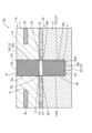
- FIG. 2 is an enlarged cross-sectional view of the holding device showing the vicinity of a connection point between the first gas flow path and the second gas flow path
- FIG. 2 is an explanatory diagram showing the positional relationship between the upper end surface of a first porous body and the upper end surface of a second porous body when viewed in a plan view
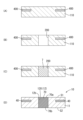
- FIG. 1 is a schematic diagram illustrating a method for manufacturing a holding substrate
- FIG. 1 is a schematic diagram illustrating a method for manufacturing a base.
- FIG. 11 is an enlarged cross-sectional view of a connection portion between a first gas flow passage and a second gas flow passage of a holding device according to a second embodiment
- FIG. 11 is an enlarged cross-sectional view of a connection portion between a first gas flow passage and a second gas flow passage of a holding device according to a third embodiment
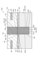
- FIG. 13 is an enlarged cross-sectional view of a connection portion between a first gas flow passage and a second gas flow passage of a holding device according to a fourth embodiment
- FIG. 13 is an explanatory diagram showing a schematic cross-sectional configuration of a part of a holding device according to a fifth embodiment
- the holding device 100 is an electrostatic chuck that attracts and holds an object (e.g., a wafer W) by electrostatic attraction.
- the electrostatic chuck is used as a table on which the wafer W is placed in a process of etching using plasma in a reduced pressure chamber, for example.
- FIG. 1 is an explanatory diagram that shows a schematic cross-sectional configuration of a holding device 100 according to the first embodiment.
- FIG. 1 shows a schematic cross-sectional configuration of the holding device 100 cut vertically (up and down).
- the holding device 100 comprises a disk-shaped holding substrate (ceramic substrate) 10 and a disk-shaped base (base member) 20 that is larger than the holding substrate 10.
- the holding substrate 10 and the base 20 are stacked on top of each other in the vertical direction, with the holding substrate 10 placed on the upper side and the base 20 placed on the lower side.
- the holding substrate 10 and the base 20 are bonded to each other by a bonding material 30 interposed between them.
- the holding substrate 10 has a substantially circular first surface S1 arranged on the upper side, and a substantially circular second surface S2 arranged on the opposite side (i.e., the lower side) of the first surface S1 and facing the base 20.
- the base 20 has a substantially circular third surface S3 arranged on the upper side and facing the second surface S2 of the holding substrate 10, and a substantially circular fourth surface S4 arranged on the opposite side (i.e., the lower side) of the third surface S3.
- the above-mentioned bonding material 30 is sandwiched between the second surface S2 of the holding substrate 10 and the third surface S3 of the base 20 and is spread out in a layer.
- the holding substrate 10 comprises a disk-shaped plate-like member 11 and a first gas 12 formed inside the plate-like member 11.
- the upper surface of the plate-like member 11 becomes the first surface S1 of the holding substrate 10, and the lower surface of the plate-like member 11 becomes the second surface S2 of the holding substrate 10.
- the plate-shaped member 11 is a plate-shaped (disk-shaped) insulating member whose main component is ceramic.
- main component means the component with the highest content.
- the plate-shaped member 11 is made of alumina (Al2O3). In other embodiments, the plate-shaped member 11 may be made of other ceramics, such as aluminum nitride (AlN).
- FIG. 2 is a cross-sectional view of the holding device 100 with the first gas flow path 12 and the second gas flow path 22 enlarged.
- FIG. 2 shows a schematic cross-sectional structure of the holding substrate 10 cut along the thickness direction (vertical direction).
- the first gas flow path 12 constitutes a part of the flow path 60 for flowing an inert gas (for example, helium gas, which is a thermally conductive gas) provided in the holding device 100.
- the first gas flow path 12 is formed inside the plate-like member 11 of the holding substrate 10.
- the first gas flow path 12 is made of holes penetrating the holding substrate 10 in the thickness direction (vertical direction), including a first gas inlet 12a opening on the second surface S2 side of the holding substrate 10 (plate-like substrate 11) and a gas outlet 12b opening on the first surface S1 side.
- first gas inlet 12a opening on the second surface S2 side of the holding substrate 10 (plate-like substrate 11)
- gas outlet 12b opening on the first surface S1 side.
- the first gas flow path 12 includes a cylindrical first vertical flow path section 120 that extends from the first gas inlet 12a toward the first surface S1 and in the thickness direction (up and down direction) of the plate-like member 11.
- the entire first gas flow path 12 is made up of the first vertical flow path section 120.
- the first vertical flow path section 120 extends in the thickness direction of the plate-like member 11 so as to connect the first gas outlet 12b and the first gas inlet 12a.
- a gas-permeable first porous body 70 (described later) mainly composed of ceramics is filled inside the first vertical flow path section 120.
- the first gas inlet 12a side is the upstream side
- the first gas outlet 12b side is the downstream side
- the holding substrate 10 further includes a chuck electrode 40, which is an electrode member.
- the chuck electrode 40 is generally planar (layered) and generally parallel to the first surface S1.
- the chuck electrode 40 is made of an electrically conductive material such as tungsten, molybdenum, or platinum.
- the chuck electrode 40 is disposed on the first surface S1 side inside the holding substrate 10 (plate-shaped member 11).
- the chuck electrode 40 is connected to an external power source via a terminal or the like. When power is supplied to the chuck electrode 40, an electrostatic force is generated, and the wafer W is attracted and held to the first surface S1 of the holding substrate 10 by this electrostatic force.
- the chuck electrode 40 has a through hole 41 that penetrates in the thickness direction (vertical direction). In other embodiments, a high-frequency electrode or a heater electrode may be provided as the electrode member.
- the first surface S1 of the holding substrate 10 is provided with a plurality (a large number) of first gas flow outlets 12b. For ease of explanation, only two first gas flow outlets 12b are shown in FIG. 1.
- the base 20 comprises a disk-shaped plate-shaped base member 21 and a second gas flow path 22 formed inside the plate-shaped base member 21.
- the plate-shaped base member 21 is a plate-shaped member made of a metallic material that constitutes the base (base member) 20.
- the plate-shaped base member 21 has a third surface S3 that faces the second surface S2 of the holding substrate 10 (plate-shaped member 11) and a fourth surface S4 that is disposed on the opposite side of the third surface S3.
- the plate-shaped base member 21 is disposed on the second surface S2 side of the plate-shaped member 11 of the holding substrate 10.
- the plate-shaped base member 21 of the base 20 is made of, for example, a metal-based material such as a metal (aluminum, aluminum alloy, etc.), a composite of metal and ceramics (Al-SiC), or a ceramic material such as SiC.
- a metal-based material such as a metal (aluminum, aluminum alloy, etc.), a composite of metal and ceramics (Al-SiC), or a ceramic material such as SiC.
- a coolant flow path 23 is provided inside the base 20.
- Plasma heat is cooled by flowing a coolant (e.g., a fluorine-based inert liquid, water, etc.) through the coolant flow path 23.
- a coolant e.g., a fluorine-based inert liquid, water, etc.
- the base 20 is cooled, and the holding substrate 10 is cooled by heat transfer (heat withdrawal) between the base 20 and the holding substrate 10 via the bonding material 30.
- the wafer W held on the first surface S1 of the holding substrate 10 is cooled.
- the temperature of the wafer W held on the first surface S1 can be controlled by appropriately adjusting the flow rate of the coolant through the coolant flow path 23.
- the second gas flow path 22 is provided inside the base 20 and constitutes a part of the flow path 60.
- the second gas flow path 22 is in the form of a hole penetrating the inside of the base 20, and has a second gas outlet 22b that opens on the third surface S3 side of the plate-shaped base member 21 and faces the first gas inlet 12a, and a second gas inlet 22a that opens on the fourth surface S4 side of the plate-shaped base member 21.
- the second gas inlet 22a forms the inlet of the second gas flow path 22 and also forms the inlet of the entire flow path 60 provided in the holding device 100.
- the second gas inlet 22a side is the upstream side
- the second gas outlet 22b side is the downstream side
- the second gas flow path 22 includes a cylindrical second vertical flow path section 220 that extends from the second gas outlet 22b toward the fourth surface S4 and in the thickness direction (vertical direction) of the plate-like base member 21.
- the second vertical flow path section 220 is cylindrical with a bottom, and the open end of the second vertical flow path section 220 serves as the second gas outlet 22b.
- a gas-permeable second porous body 80 (described later) mainly composed of ceramics is filled inside this second vertical flow path section 220.
- the second vertical flow path section 220 has a cylindrical peripheral surface 220a and a bottom surface 220b that is circular in plan view and is disposed on the fourth surface S4 side of the peripheral surface 220a.
- An opening 221 is provided at approximately the center of the bottom surface 220b.
- a cylindrical vertical flow path section 222 extending in the thickness direction of the plate-like base member 21 is provided from the opening 221 to the fourth surface S4 side.
- a horizontal flow path section 223 extending parallel to the third surface S3 is provided at the lower end of the vertical flow path section 222.
- a cylindrical vertical flow path section 224 extending in the thickness direction of the plate-like base member 21 is provided from the upstream end of the vertical flow path section 222 to the fourth surface S4 side.
- the inner diameters of the vertical flow path section 222, the horizontal flow path section 223, and the vertical flow path section 224 are smaller than the inner diameter of the second vertical flow path section 220.
- the bonding material 30 is composed of, for example, a silicone-based organic bonding agent, an inorganic bonding agent, or a bonding sheet containing an Al-based metal adhesive. It is preferable that the bonding material 30 has high adhesive strength to both the holding substrate 10 and the base 20, as well as high pressure resistance and thermal conductivity.
- the joining material 30 also has a joining-side gas flow path 31 that constitutes part of the flow path 60.
- the joining-side gas flow path 31 is made of a hole that penetrates the layered joining material 30 in the thickness direction.
- the flow path 60 supplies an inert gas (such as helium gas) to the first surface S1 side of the holding device 100.
- an inert gas such as helium gas
- the first surface S1 is provided with a large number of first gas outlets 12b, which are outlets of the flow path 60, and the inert gas is supplied to the first surface S1 side by being discharged from each of the first gas outlets 12b.
- such a flow path 60 is composed of the second gas flow path 22, the joining side gas flow path 31, and the first gas flow path 12.
- the inlet of the flow path 60 consists of a second gas inlet 22a, and multiple second gas inlets 22a are provided on the fourth surface S4 of the base 20 (plate-shaped base member 21).
- the inert gas passes through the second gas flow path 22 connected to each second gas inlet 22a, the joining side gas flow path 31, and the first gas flow path 12 in sequence, and is finally discharged from multiple first gas outlets 12b provided on the first surface S1.
- the second gas outlet 22b of the second gas flow passage 22 is connected to an opening on the lower side (the base 20 side) of the joining side gas flow passage 31.
- an opening on the upper side (the holding substrate 10 side) of the joining side gas flow passage 31 is connected to a first gas inlet 12a of the first gas flow passage 12.
- a plurality of first gas inlets 12a of the first gas flow passage 12 are provided on the second surface S2 of the holding substrate 10.
- the horizontal flow path section 223 of the second gas flow path 22 described above is connected to a plurality of vertical flow path sections and a second vertical flow path section (not shown).
- a second gas flow path 22 is formed inside the base 20 (plate-shaped base member 21) and is branched into a plurality of sections from the upstream side to the downstream side.
- a first gas flow path (first vertical flow path section) (not shown) formed in the holding substrate 10 (plate-shaped member 11) is connected to each second vertical flow path section.
- the first porous body 70 and the second porous body 80 are intended to suppress the occurrence of abnormal discharge (arcing) caused by the inert gas (helium) in the first gas flow passage 12 and the second gas flow passage 22.
- the first porous body 70 is filled in the first vertical flow passage portion 120 of the first gas flow passage 12 provided in the holding substrate 10.
- the first porous body 70 is a gas-permeable member containing a large number of pores, mainly composed of insulating ceramics.
- the first porous body 70 is cylindrical and extends in the vertical direction (thickness direction of the holding substrate 10), and a mesh-like ventilation path is formed inside the first porous body 70 to allow the inert gas to pass through.
- the first porous body 70 has a so-called open-cell structure.
- the ventilation path is made up of a large number of pores connected to each other within the first porous body 70.
- the pores are formed as traces of particulate pore-forming material burned (disappeared) during the manufacture (firing) of the first porous body 70.
- synthetic resin beads or carbon powder are used as the pore-forming material.
- the upper end surface 70a of the first porous body 70 is circular in plan view and is exposed upward from the gas flow outlet 12b opening on the first surface S1 side of the plate-like member 11.
- the first surface S1 and the upper end surface 70a are arranged to be flush with each other.
- the lower end surface 70b of the first porous body 70 is circular in plan view and is exposed from the first gas flow inlet 12a opening on the second surface S2 side of the plate-like member 11 toward the second porous body 80 below.
- the upper end surface 70a and the lower end surface 70b are set to be the same size.
- the second surface S2 and the lower end surface 70b are arranged to be flush with each other.
- the peripheral surface 70c of the first porous body 70 and the cylindrical inner peripheral surface 120a of the first vertical flow path section 120 (plate-like member 11) are sintered to each other.
- the first porous body 70 and the first vertical flow path section 120 (plate-shaped member 11) are integrated with each other by solid-state bonding.
- the second porous body 80 is filled in the second vertical flow passage portion 220 of the second gas flow passage 22 provided in the base 20.
- the second porous body 80 is a gas-permeable member containing a large number of pores, mainly composed of insulating ceramics, similar to the first porous body 70.
- the second porous body 80 is cylindrical and extends in the vertical direction (thickness direction of the base 20), and a mesh-like ventilation path is formed inside the second porous body 80 to allow the inert gas to pass through.
- the second porous body 80 has a so-called open-cell structure.
- the ventilation path is made up of a large number of pores connected to each other within the second porous body 80.
- the pores are formed as traces of particulate pore-forming material burned (disappeared) during the manufacture (firing) of the second porous body 80.
- synthetic resin beads or carbon powder are used as the pore-forming material.
- the upper end surface 80a of the second porous body 80 is circular in plan view and is exposed from the second gas outlet 22b opening on the third surface S3 side of the plate-shaped base member 21 toward the first porous body 70 above.
- the third surface S3 and the upper end surface 80a are arranged to be flush with each other.
- the lower end surface 80b of the second porous body 80 is circular in plan view and is superimposed on the bottom surface 220b of the second vertical flow path section 220.
- a portion of the lower end surface 80b that overlaps with the opening 221 provided at approximately the center of the bottom surface 220b is exposed to the vertical flow path section 222 side, and the inert gas supplied from the vertical flow path section 222 side is introduced into the second porous body 80 from the exposed lower end surface 80b.
- the upper end surface 80a and the lower end surface 80b are set to be the same size as each other.
- An adhesive 9 is interposed between the peripheral surface 80c of the second porous body 80 and the peripheral surface 220a of the second vertical flow path section 220, and the adhesive force of this adhesive 9 is used to fix the second porous body 80 within the second vertical flow path section 220.
- FIG. 3 is an explanatory diagram showing the positional relationship between the upper end surface 70a of the first porous body 70 and the upper end surface 80a of the second porous body 80 when viewed in a plan view.
- the first porous body 70 in the first vertical flow path section 120 and the second porous body 80 in the second vertical flow path section 220 are arranged so as to overlap each other.
- the diameter (outer diameter) of the first porous body 70 is set to be larger than the diameter (outer diameter) of the second porous body 80. In other embodiments, the diameter of the first porous body and the diameter of the second porous body may be the same.
- the plasma resistance (plasma resistance) of the first porous body 70 is set to be higher than the plasma resistance (plasma resistance) of the second porous body 80.
- first skeletal portion the portion of the first porous body 70 other than the pores
- second skeletal portion the portion of the second porous body 80 other than the pores
- the ceramics constituting the first porous body 70 i.e., the ceramics constituting the first skeletal portion
- the ceramics constituting the second porous body 80 i.e., the ceramics constituting the second skeletal portion
- the purity of the ceramic (alumina) that constitutes the first porous body 70 is set to be higher than the purity of the ceramic (alumina) that constitutes the second porous body 80.
- the purity of the ceramic (alumina) that constitutes the first porous body 70 there are no particular restrictions on the purity of the ceramic (alumina) that constitutes the first porous body 70 as long as it does not impair the objective of the present invention, but for example, 99.0% or more is preferable, and 99.9% or more is more preferable.
- the glass content (content ratio) of the first porous body 70 is preferably smaller than the glass content (content ratio) of the second porous body 80.
- the first porous body 70 (first skeletal portion) and the second porous body 80 (second skeletal portion) each contain a glass component (SiO 2 ) derived from the binder used during production.
- the glass content of the second porous body 80 is preferably, for example, 0.1% to 10%. Ceramic powders such as alumina powder tend to sinter at low temperatures when the glass content is high. Generally, porous bodies such as the second porous body 80 tend to have poor sinterability compared to dense bodies because the contact area between ceramic powder particles is structurally smaller. However, adding glass components as a binder to the ceramic powder makes it easier to manufacture the porous body. Moreover, since the porous body is easier to sinter at low temperatures, the energy required to manufacture the porous body can be reduced, which is advantageous in terms of cost.
- the purity of the ceramic (alumina) constituting the second porous body 80 is not particularly limited as long as it does not impair the objective of the present invention, but for example, 95.0% or more is preferable, and 97.0% or more is more preferable.
- the purity of each ceramic of the first porous body 70 and the second porous body 80 can be adjusted by appropriately setting the purity of the ceramic powder used in manufacturing the first porous body 70 and the second porous body 80, and the amount of components used other than the ceramic powder (e.g., binder, dispersant, plasticizer, etc.).
- the amount of components used other than the ceramic powder e.g., binder, dispersant, plasticizer, etc.
- the porosity of the second porous body 80 is set to be equal to or greater than the porosity of the first porous body 70.
- the porosity of the first porous body 70 is not particularly limited as long as it does not impair the object of the present invention, but is preferably 50% or more, more preferably 55% or more, even more preferably 60% or more, preferably 80% or less, more preferably 75% or less, and even more preferably 70% or less.
- the porosity of the first porous body 70 is in such a range, it is easy to set the porosity of the second porous body 80 to be equal to or greater than the porosity of the first porous body 70 while ensuring the gas permeability of each of the first porous body 70 and the second porous body 80.
- the inert gas passes through the vertical flow path section 224, the horizontal flow path section 223, and the vertical flow path section 222, which constitute the second gas flow path 22, in that order, and reaches the second vertical flow path section 220, which is connected to the downstream end of the vertical flow path section 222.
- the inert gas that reaches the second vertical flow path section 220 enters the second vertical flow path section 220 through the opening 221 provided in the bottom surface 220b, and is introduced into the second porous body 80 from the lower end surface 80b exposed from the opening 221.
- the inert gas introduced into the second porous body 80 passes through the ventilation path in the second porous body 80 and is discharged from the upper end surface 80a in the second gas outlet 22b to the joining side gas flow path 31 side.
- the discharged inert gas passes through the joint side gas flow passage 31 and is introduced into the first porous body 70 filled in the first vertical flow passage section 120 from the lower end surface 70b of the first gas inlet 12a.
- the inert gas introduced into the first porous body 70 passes through the ventilation path in the first porous body 70 and is discharged to the outside from the upper end surface 70a of the first gas outlet 12b.
- the inert gas passes through the first porous body 70 and the second porous body 80, which are arranged so as to overlap each other in the vertical direction, and is discharged from each of the first gas outlets 12b provided on the first surface S1 side of the holding substrate 10.
- the first porous body 70 filled in the first gas flow path 12 (first vertical flow path section 120) of the holding substrate 10 is more susceptible to exposure to plasma during plasma processing (plasma etching, etc.) than the second porous body 80 arranged below it in an overlapping manner.
- the plasma resistance (plasma resistance) of the first porous body 70 is set to be higher than the plasma resistance (plasma resistance) of the second porous body 80. Therefore, in the holding device 100 of this embodiment, in particular, the gas permeability of the first porous body 70 is ensured, while damage to the first porous body 70 by plasma is suppressed.
- the holding device 100 of this embodiment is provided inside a first gas flow path 12 and a second gas flow path 22 (an example of a gas flow path) for supplying an inert gas, and includes a first porous body 70 and a second porous body 80 (an example of a porous body) that are gas permeable and have excellent plasma resistance.
- FIG. 4 is an explanatory diagram that shows a schematic representation of the manufacturing method for the holding substrate 10.
- This manufacturing method for the holding substrate 10 is an application of a sheet lamination method that uses green sheets (ceramic green sheets).
- a plurality of green sheets for forming the plate-like member 11 of the holding substrate 10 are stacked to form the first laminate 110.
- a conductor layer 400 is formed on a specific green sheet constituting the first laminate 110, and such a green sheet is stacked on other green sheets.
- the slurry for green sheets is obtained, for example, by mixing a mixture containing alumina powder, acrylic binder, dispersant, plasticizer, etc., with an organic solvent added, using a ball mill. This slurry is formed into a sheet using a casting device, and the resulting molded product is then dried to obtain multiple green sheets.
- the metallization paste for forming the conductor layer 400 can be obtained by, for example, adding conductive powder such as tungsten or molybdenum to a mixture of alumina powder, acrylic binder, and organic solvent, and kneading the mixture.
- the conductor layer 400 is formed on a specific green sheet by printing this metallization paste using, for example, a screen printing device.
- holes 200 for forming the first gas flow path 12 are formed at predetermined locations of the first laminate 400.
- the holes 200 are provided in a generally cylindrical shape penetrating the first laminate 400 in the thickness direction.
- the holes 200 are formed at predetermined locations of the first laminate 400 using a known processing device (router, etc.).
- the holes 200 of the first laminate 400 are filled with a paste 7 for a first porous body to form a first porous body 70.
- the paste 7 for a first porous body is obtained, for example, by kneading a mixture containing alumina powder, a pore former, a binder, an organic solvent, etc.
- the amounts of alumina powder, pore former, etc. used in the paste 7 for a first porous body are appropriately set so that the purity of the first skeleton of the first porous body 70 and the porosity of the first porous body 70 are predetermined values.
- Methods for filling the holes 200 with the first porous body paste 7 include, for example, a method using an injection molding device, a method using a screen printing device, etc.
- the first laminate 110 in which the holes 200 are filled with the first porous body paste 7 is dried as appropriate.
- the outer periphery of the first laminate 110 may be cut as appropriate.
- the first laminate is then cut by machining to produce a disk-shaped molded body.
- the resulting molded body is then degreased and fired, and the degreased and fired molded body is then fired (main firing) to obtain a fired body.
- the first porous body 70 and the first vertical flow path 120 are solid-phase bonded to each other.
- the size of the hole 200 and the amount of the paste 7 for the first porous body filled in the hole 200 are appropriately set taking into account shrinkage during firing.
- the surface of the fired body is polished or otherwise processed to obtain a holding substrate 10 having a plate-shaped member 11 as shown in FIG. 4(D).
- FIG. 5 is an explanatory diagram that shows a schematic representation of the manufacturing method of the base 20.
- a first plate-shaped base member 211 made of a metal material such as aluminum is prepared, and the second vertical flow path portion 220 and the vertical flow path portion 222 of the second gas flow path 22 are formed by, for example, cutting predetermined portions of the first plate-shaped base member 211.
- the second vertical flow path portion 220 and the vertical flow path portion 222 are formed by a known hole forming method.
- This first plate-shaped base member 211 constitutes the upper portion (third surface S3 side) of the plate-shaped base member 21.
- a separately manufactured sintered second porous body 80 is coated with uncured adhesive 9 on its peripheral surface 80c, and the body is placed in the second vertical flow passage section 220 of the first plate-shaped base member 211.
- the second porous body 80 is made by sintering a paste for the second porous body for forming the second porous body 80.
- the paste for the second porous body is obtained by kneading a mixture containing, for example, alumina powder, a pore former, a binder (glass component), an organic solvent, etc.
- the amount of alumina powder, a pore former, etc. used in the paste for the second porous body is appropriately set so that the purity of the second skeleton part of the second porous body 80 and the porosity of the second porous body 80 are predetermined values.
- a cylindrical molded body is made from such a paste for the second porous body, and the molded body is degreased and fired, and the second porous body 80 is obtained by firing it.
- the second porous body 80 can use more binder (glass component) for making it easier to sinter ceramic powders (alumina powders) together than the first porous body 70, so there is a higher degree of freedom in the size of the pores, etc., and it is easier to ensure gas permeability.
- the adhesive 9 is not particularly limited as long as it has heat resistance and can bond the second porous body 80 (e.g., a ceramic material) and the first plate-shaped base member 211 (e.g., a metal-based material), and for example, silicone resin is used.
- the uncured adhesive 9 may be applied to the entire peripheral surface 80c of the second porous body 80, or may be applied partially.
- the first plate-shaped base member 211 After the second porous body 80 with adhesive 9 is placed in the second vertical flow passage section 220 of the first plate-shaped base member 211, the first plate-shaped base member 211 in this state is heated as necessary to harden the adhesive 9.
- a second plate-shaped base member 212 made of the same metal-based material as the first plate-shaped base member 211 is prepared, and the second plate-shaped base member 212 is cut at predetermined locations to form the horizontal flow path portion 223 and the vertical flow path portion 224 of the second gas flow path 22.
- the upper surface of the second plate-shaped base member 212 on which the horizontal flow path portion 223 and the vertical flow path portion 224 are formed and the lower surface of the first plate-shaped base member 211 on which the second porous body 80 is filled in the second gas flow path 22 (second vertical flow path portion 220) are joined to each other by a known joining technique such as brazing or EB welding, thereby obtaining a base 20 equipped with the plate-shaped base member 20.
- the holding substrate 10 and base 20 are fabricated, they are bonded together using a bonding material 30.
- the bonding of the holding substrate 10 and base 20 using the bonding material 30 is essentially the same as that used in conventional products. Therefore, a detailed description of this is omitted. In this manner, the holding device 100 is manufactured.
- FIG. 6 is an enlarged cross-sectional view of the vicinity of the connection point between the first gas flow path 12A and the second gas flow path 22A of the holding device 100A according to embodiment 2.
- the basic configuration of the holding substrate 10A and the base 20A of this embodiment is the same as that of embodiment 1. Therefore, in Fig. 6, the parts corresponding to embodiment 1 are denoted by the same reference numerals as embodiment 1 with the addition of the reference numeral "A", and detailed description thereof will be omitted.
- the holding substrate 10A comprises a disk-shaped plate-like member 11A and a first gas flow path 12A formed therein.
- the upper surface of the plate-like member 11A becomes the first surface SA1 of the holding substrate 10A
- the lower surface of the plate-like member 11A becomes the second surface SA2 of the holding substrate 10A.
- the base 20A comprises a disk-shaped plate-like base member 21A and a second gas flow path 22A formed inside the plate-like base member 21A.
- the upper surface of the plate-like base member 21A becomes the third surface SA3 of the base 20A
- the lower surface of the plate-like base member 21A becomes the fourth surface (not shown) of the base 20A.
- a first porous body 70A is filled in the first vertical flow path section 120A of the first gas flow path 12A, and a second porous body 80A is filled in the second vertical flow path section 220A of the second gas flow path 22A.
- the plasma resistance (plasma resistance) of the first porous body 70A is set to be higher than the plasma resistance (plasma resistance) of the second porous body 80A.
- the ceramic that constitutes the first porous body 70A is yttria
- the ceramic that constitutes the second porous body 80A is alumina.
- yttria which has better plasma resistance than alumina, may be used as the ceramic that constitutes the first porous body 70A, which is easily exposed to plasma.
- the purity of the ceramic (yttria) constituting the first porous body 70A in this embodiment is not particularly limited as long as it does not impair the objective of the present invention, but for example, 99.0% or more is preferable, and 99.9% or more is more preferable.
- the purity of the ceramic (alumina) constituting the second porous body 80A is not particularly limited as long as it does not impair the objective of the present invention, but for example, 95.0% or more is preferable, and 97.0% or more is more preferable.
- the purity of the ceramic (yttria) of the first porous body 70A is higher than the purity of the ceramic (alumina) of the second porous body 80A.
- the purity of each ceramic of the first porous body 70A and the second porous body 80A can be adjusted by appropriately setting the purity of the ceramic powder (yttria powder, alumina powder) used in manufacturing the first porous body 70A and the second porous body 80A, and the amount of components used other than the ceramic powder (e.g., binder, dispersant, plasticizer, etc.).
- the ceramic powder yttria powder, alumina powder
- the amount of components used other than the ceramic powder e.g., binder, dispersant, plasticizer, etc.
- the porosity of the second porous body 80A is set to be equal to or greater than the porosity of the first porous body 70A.
- the porosity of the first porous body 70A is not particularly limited as long as it does not impair the object of the present invention, but is preferably 50% or more, more preferably 55% or more, even more preferably 60% or more, preferably 80% or less, more preferably 75% or less, and even more preferably 70% or less.
- the porosity of the first porous body 70A is in such a range, it is easy to set the porosity of the second porous body 80A to be equal to or greater than the porosity of the first porous body 70 while ensuring the gas permeability of each of the first porous body 70A and the second porous body 80A.
- the ceramic constituting the first porous body 70A is yttria, and the ceramic constituting the second porous body 80A is alumina, so that the plasma resistance (plasma resistance) of the first porous body 70A is set to be higher than the plasma resistance (plasma resistance) of the second porous body 80A. Therefore, in particular, the gas permeability of the first porous body 70A is ensured, while damage to the first porous body 70A by plasma is suppressed.
- the holding device 100A of this embodiment is provided inside a first gas flow path 12A and a second gas flow path 22A (an example of a gas flow path) for supplying an inert gas, and includes a first porous body 70A and a second porous body 80A (an example of a porous body) that are gas permeable and have excellent plasma resistance.
- Fig. 7 is an enlarged cross-sectional view of the vicinity of the connection point between the first gas flow path 12B and the second gas flow path 22B of the holding device 100B according to the third embodiment.
- the basic configuration of the holding substrate 10B and the base 20B of this embodiment is the same as that of the first embodiment. Therefore, in Fig. 7, the parts corresponding to those of the first embodiment are denoted by the same reference numerals as those of the first embodiment, with the reference numeral "B" added thereto, and detailed description thereof will be omitted.
- the holding substrate 10B comprises a disk-shaped plate-like member 11B and a first gas flow path 12B formed therein.
- the upper surface of the plate-like member 11B becomes the first surface SB1 of the holding substrate 10B, and the lower surface of the plate-like member 11B becomes the second surface SB2 of the holding substrate 10B.
- the base 20B comprises a disk-shaped plate-like base member 21B and a second gas flow path 22B formed inside the plate-like base member 21B.
- the upper surface of the plate-like base member 21B becomes the third surface SB3 of the base 20B, and the lower surface of the plate-like base member 21B becomes the fourth surface (not shown) of the base 20B.
- the first vertical flow passage portion 120B of the first gas flow passage 12B is filled with a first porous body 70B
- the second vertical flow passage portion 220B of the second gas flow passage 22B is filled with a second porous body 80B.
- the ceramic constituting the first porous body 70B is alumina
- the ceramic constituting the second porous body 80B is alumina.
- the plasma resistance (plasma resistance) of the first porous body 70B is set to be higher than the plasma resistance (plasma resistance) of the second porous body 80B.
- the shape of the first gas flow path 12B (first vertical flow path section 120B) formed in the plate-like member 11B of the holding substrate 10B and the shape of the first porous body 70B filled in the first gas flow path 12B (first vertical flow path section 120B) are different from those in embodiment 1.
- the first porous body 70B in this embodiment has a multi-stage shape in which the outer diameter increases stepwise from the first surface SB1 side toward the second surface SB2 side.
- the first porous body 70B has a shape in which a disk-shaped small diameter section 71B, a disk-shaped medium diameter section 72B having an outer diameter larger than the small diameter section 71B, and a disk-shaped large diameter section 73B having an outer diameter larger than the medium diameter section 72B are concentrically stacked in this order from the first surface SB1 side to the second surface SB2 side.
- the first vertical flow passage section 120B of the first gas flow passage 12B which is filled with the first porous body 70B, has a multi-step shape in which the inner diameter increases stepwise from the first surface SB1 side to the second surface SB2 side.
- the upper end surface of the small diameter section 71B becomes the upper end surface 70Ba of the first porous body 70B
- the lower end surface of the large diameter section 73B becomes the lower end surface 70Bb of the first porous body 70B.
- the first gas flow passage 12B has a circular shape in a plan view, as in the first embodiment.
- the first gas flow passage 12B has a circular shape larger than the first gas flow passage 12Bb in a plan view.
- the first gas flow passage 12B has a circular shape larger than the second gas flow passage 22Bb in a plan view, and faces the second gas flow passage 22Bb.
- the peripheral surface 70Bc (external surface excluding the upper end surface 70Ba and the lower end surface 70Bb) of the first porous body 70B and the inner peripheral surface 120Ba of the first vertical flow path section 120B (plate-shaped member 11B) are sintered together.
- the first porous body 70B and the first vertical flow path section 120B (plate-shaped member 11B) are integrated together by solid-state bonding.
- each ceramic constituting the first porous body 70B and the second porous body in this embodiment are appropriately set in the same manner as in embodiment 1 so that the plasma resistance (plasma resistance) of the first porous body 70B is higher than the plasma resistance (plasma resistance) of the second porous body 80B.
- the lower end surface 70Bb of the multi-stage first porous body 70B is likely to overlap the upper end surface 80Ba of the cylindrical second porous body 80B filled in the second vertical flow path section 220B in a plan view.
- the shape of the first porous body 70B and the shape of the second porous body 80B may be different from each other, and the lower end surface 70Bb of the first porous body 70B may be set larger than the upper end surface 70Ba of the second porous body 80B.
- the plasma resistance (plasma resistance) of the first porous body 70B is set to be higher than the plasma resistance (plasma resistance) of the second porous body 80B, and therefore, in particular, the gas permeability of the first porous body 70B is ensured while preventing the first porous body 70B from being damaged by plasma.
- the holding device 100B of this embodiment is provided inside a first gas flow path 12B and a second gas flow path 22B (an example of a gas flow path) for supplying an inert gas, and includes a first porous body 70B and a second porous body 80B (an example of a porous body) that are gas permeable and have excellent plasma resistance.
- Fig. 8 is an enlarged cross-sectional view of the vicinity of a connection point between a first gas flow path 12C and a second gas flow path 22C of the holding device 100C according to the fourth embodiment.
- the basic configurations of the holding substrate 10C and the base 20C of this embodiment are the same as those of the first embodiment. Therefore, in Fig. 8, parts corresponding to those of the first embodiment are denoted by the same reference numerals as those of the first embodiment with the addition of the reference numeral "C", and detailed description thereof will be omitted.
- the first vertical flow passage section 120C of the first gas flow passage 12C is filled with a first porous body 70C
- the second vertical flow passage section 220C of the second gas flow passage 22C is filled with a second porous body 80C.
- the ceramic constituting the first porous body 70C is alumina
- the ceramic constituting the second porous body 80C is alumina.
- the plasma resistance (plasma resistance) of the first porous body 70C is set to be higher than the plasma resistance (plasma resistance) of the second porous body 80C.
- the upper end 81C of the second porous body 80C is configured to protrude upward (toward the holding substrate 10C) from the second gas outlet 22Cb of the second vertical flow path section 220C so that the upper end surface 80Ca of the second porous body 80C abuts the lower end surface 70Cb of the first porous body 70C.
- the second porous body 80C of this embodiment is configured to have a long length in the vertical direction so as to fill the gap formed between the first porous body 70 and the second porous body 80 of embodiment 1, for example.
- An adhesive 9C is interposed between the peripheral surface 80Cc of the second porous body 80C and the peripheral surface 220Ca of the second vertical flow path section 220C, and the adhesive force of this adhesive 9C is used to fix the second porous body 80C in the second vertical flow path section 220C.
- a bonding material 30C is disposed around the upper end 81C of the second porous body 80C protruding from the second gas outlet 22Cb disposed on the third surface SC3 side.
- the holding substrate 10C and the base 20C are bonded to each other by the bonding material 30C disposed between them.
- the peripheral surface 70Cc of the first porous body 70C and the inner peripheral surface 120Ca of the first vertical flow path section 120C (plate-shaped member 11C) are sintered together.
- the first porous body 70C and the first vertical flow path section 120C (plate-shaped member 11C) are integrated with each other by solid-state bonding.
- each ceramic constituting the first porous body 70C and the second porous body 80C in this embodiment are appropriately set in the same manner as in embodiment 1 so that the plasma resistance (plasma resistance) of the first porous body 70C is higher than the plasma resistance (plasma resistance) of the second porous body 80C.
- the upper end 81C of the second porous body 80C may be configured to protrude upward from the second gas outlet 22Cb on the third surface SC3 so that the upper end surface 80Ca of the second porous body 80C abuts the lower end surface 70Cb of the first porous body 70C.
- Fig. 9 is an explanatory diagram that shows a schematic cross-sectional configuration of a portion of the holding device 100D according to the fifth embodiment.
- parts corresponding to those in the first embodiment are given the same reference numerals as those in the first embodiment with the addition of the reference numeral "D", and detailed description thereof will be omitted.
- the holding substrate 10D comprises a disk-shaped plate member 11D and a first gas flow path 12D formed therein.
- the plate-like member 11D has, in a plan view, a disk-shaped mounting portion 111D having a predetermined thickness arranged toward the center, and an annular flange portion 112D extending radially outward from the mounting portion 111D.
- the thickness of the flange portion 112D is smaller than that of the mounting portion 111D, and the upper surface 112D1 of the flange portion 112D is set to be lower in height than the upper surface 111D1 of the mounting portion 111D.
- the wafer WD is placed on the upper surface 111D1 of the mounting portion 111D.
- the upper surface 111D1 of the mounting portion 111D is circular in a plan view, and the upper surface 112D1 of the flange portion 112D is annular and surrounds the mounting portion 111D in a plan view.
- An annular ring (focus ring) (not shown) is disposed on the upper surface 112D1 of the flange portion 112D.
- the first surface SD1 of the holding substrate 10D is made up of the upper surface 111D1 of the mounting portion 111D and the upper surface 112D1 of the flange portion 112D.
- the second surface SD2 of the holding substrate 10D is made up of the lower surface of the plate-like member 11D.
- the base 20D comprises a disk-shaped plate-shaped base member 21D and a second gas flow path 22D formed inside the plate-shaped base member 21D.
- a refrigerant flow path 23D is provided inside the base 20D.
- the upper surface of the plate-shaped base member 21D becomes the third surface SD3 of the base 20D, and the lower surface of the plate-shaped base member 21D becomes the fourth surface SD4 of the base 20D.
- the holding substrate 10D and the base 20CD are joined to each other by a bonding material 30D interposed between them.
- the first gas flow outlets 12Db are formed not only on the upper surface 111D1 of the mounting portion 111D but also on the upper surface 112D1 of the flange portion 112D.
- the upper surface 111D1 of the mounting portion 111D is provided with a plurality (a large number) of first gas flow outlets 12Db.
- the upper surface 112D1 of the flange portion 112D is also provided with a plurality of first gas flow outlets 12Db.
- the first vertical flow path section 120D of the first gas flow path 12D is provided not only on the mounting portion 111D but also on the flange portion 112D, and the first vertical flow path section 120D is filled with the first porous body 70D.
- the first gas flow path 12D formed in the flange 112D is a hole penetrating the holding substrate 10D in the thickness direction (vertical direction), including a first gas inlet 12Da opening on the second surface SD2 side of the holding substrate 10D (plate-like substrate 11D) and a gas outlet 12Db opening on the upper surface 112D1 side (first surface SD1 side) of the flange 112D.
- the first gas flow path 12D formed in the mounting portion 111D is composed of a hole penetrating the holding substrate 10D in the thickness direction (vertical direction), including a first gas inlet 12Da opening on the second surface SD2 side of the holding substrate 10D (plate-shaped substrate 11D) and a gas outlet 12Db opening on the upper surface 111D1 side (first surface SD1 side) of the mounting portion 111D.
- the second porous body 80D is filled in the second vertical flow passage portion 220D of the second gas flow passage 22D formed in the base 20D.
- the ceramic constituting the first porous body 70D is alumina
- the ceramic constituting the second porous body 80D is alumina.
- the plasma resistance (plasma resistance) of the first porous body 70D is set to be higher than the plasma resistance (plasma resistance) of the second porous body 80D.
- the plasma resistance (plasma resistance) of the first porous body 70D may be set to be higher than the plasma resistance (plasma resistance) of the second porous body 80D not only in the gas flow path 22D of the mounting part 111D on which the wafer WD is mounted, but also in the gas flow path 22D of the flange part 112D.
- the upper end surface of the first porous body exposed from the first gas outlet may have a shape other than a circle (e.g., a polygonal shape) as long as the object of the present invention is not impaired.
- the ceramic of the first porous body in the third embodiment may be made of yttria, and the ceramic of the second porous body may be made of alumina.
- the manufacturing method of the holding device shown in the above embodiment is one example, and other manufacturing methods may be used as long as they do not impair the purpose of the present invention.
- the upper end 81C of the second porous body 80C is configured to protrude upward (toward the holding substrate 10C) from the second gas outlet 22Cb of the second vertical flow path section 220C.
- the length in the vertical direction is set long so as to fill the gap formed between the first porous body 70C and the second porous body 80C, but a gap may be provided to the extent that it does not affect the discharge.
Landscapes
- Physics & Mathematics (AREA)
- Engineering & Computer Science (AREA)
- Plasma & Fusion (AREA)
- Chemical & Material Sciences (AREA)
- Analytical Chemistry (AREA)
- Container, Conveyance, Adherence, Positioning, Of Wafer (AREA)
Abstract
Description
上述したような異常放電対策で使用される多孔質体には、十分な流量のガスを透過させるガス透過性や、プラズマ耐性が求められる。しかしながら、多孔質体におけるガス透過性とプラズマ耐性との間には、二律背反的な関係にあり、例えば、多孔質体のガス透過性を向上させようとするとプラズマ耐性が低下し、また、多孔質体のプラズマ耐性を向上させようとするとガス透過性が低下してしまうという問題があった。そのため、従来の保持装置では、多孔質体について、改善の余地があった。
本発明の目的は、不活性ガスを供給するためのガス流路の内部に設けられ、ガス透過性を備えつつ、プラズマ耐性に優れる多孔質体を備える保持装置を提供することである。
前記課題を解決するための手段は、以下の通りである。即ち、
<1> 第1表面及び前記第1表面の反対側に配される第2表面を含む板状部材と、前記第1表面側に開口した第1ガス流出口及び前記第2表面側に開口した第1ガス流入口を含み、前記板状部材の内部に形成される第1ガス流路と、前記第1ガス流路に充填され、セラミックスを主成分とするガス透過性の第1多孔質体とを有する保持基板と、前記第2表面と対向する第3表面及び前記第3表面の反対側に配される第4表面を含み、前記板状部材の前記第2表面側に配される板状ベース部材と、前記第3表面側に開口しつつ前記第1ガス流入口と対向する第2ガス流出口を含み、前記板状ベース部材の内部に形成される第2ガス流路と、前記第2ガス流路に充填され、セラミックスを主成分とするガス透過性の第2多孔質体とを有する基台とを備える保持装置であって、
前記第1ガス流路は、前記第1ガス流入口から前記第1表面側に延びつつ、前記第1多孔質体が充填される第1縦流路部を有し、前記第2ガス流路は、前記第2ガス流出口から前記第4表面側に延びつつ、平面視で前記第1多孔質体と重なる形で前記第2多孔質体が充填される第2縦流路部を有し、前記第1多孔質体の耐プラズマ性が、前記第2多孔質体の耐プラズマ性よりも高い保持装置。
本発明によれば、不活性ガスを供給するためのガス流路の内部に設けられ、ガス透過性を備えつつ、プラズマ耐性に優れる多孔質体を備える保持装置を提供することができる。
以下、実施形態1に係る保持装置100を、図1~図5を参照しつつ説明する。保持装置100は、対象物(例えば、ウェハW)を、静電引力によって吸着して保持する静電チャックである。静電チャックは、例えば減圧されたチャンバー内でプラズマを用いてエッチングを行うプロセスにおいて、ウェハWを載置するテーブルとして使用される。
次いで、実施形態2に係る保持装置100Aを、図6を参照しつつ説明する。図6は、実施形態2に係る保持装置100Aの第1ガス流路12A及び第2ガス流路22Aの接続箇所付近を拡大した断面図である。本実施形態の保持基板10A及び基台20Aの基本的な構成は、実施形態1と同じである。そのため、図6では、実施形態1と対応する部分について、実施形態1と同一の符号に更に符号「A」を追加した符号を付し、詳細な説明を省略する。
次いで、実施形態3に係る保持装置100Bを、図7を参照しつつ説明する。図7は、実施形態3に係る保持装置100Bの第1ガス流路12B及び第2ガス流路22Bの接続箇所付近を拡大した断面図である。本実施形態の保持基板10B及び基台20Bの基本的な構成は、実施形態1と同じである。そのため、図7では、実施形態1と対応する部分について、実施形態1と同一の符号に更に符号「B」を追加した符号を付し、詳細な説明を省略する。
次いで、実施形態4に係る保持装置100Cを、図8を参照しつつ説明する。図8は、実施形態4に係る保持装置100Cの第1ガス流路12C及び第2ガス流路22Cの接続箇所付近を拡大した断面図である。本実施形態の保持基板10C及び基台20Cの基本的な構成は、実施形態1と同じである。そのため、図8では、実施形態1と対応する部分について、実施形態1と同一の符号に更に符号「C」を追加した符号を付し、詳細な説明を省略する。
次いで、実施形態5に係る保持装置100Dを、図9を参照しつつ説明する。図9は、実施形態5に係る保持装置100Dの一部の断面構成を模式的に表した説明図である。図9では、、実施形態1と対応する部分について、実施形態1と同一の符号に更に符号「D」を追加した符号を付し、詳細な説明を省略する。
本発明は上記記述及び図面によって説明した実施形態に限定されるものではなく、例えば次のような実施形態も本発明の技術的範囲に含まれる。
Claims (8)
- 第1表面及び前記第1表面の反対側に配される第2表面を含む板状部材と、前記第1表面側に開口した第1ガス流出口及び前記第2表面側に開口した第1ガス流入口を含み、前記板状部材の内部に形成される第1ガス流路と、前記第1ガス流路に充填され、セラミックスを主成分とするガス透過性の第1多孔質体とを有する保持基板と、
前記第2表面と対向する第3表面及び前記第3表面の反対側に配される第4表面を含み、前記板状部材の前記第2表面側に配される板状ベース部材と、前記第3表面側に開口しつつ前記第1ガス流入口と対向する第2ガス流出口を含み、前記板状ベース部材の内部に形成される第2ガス流路と、前記第2ガス流路に充填され、セラミックスを主成分とするガス透過性の第2多孔質体とを有する基台とを備える保持装置であって、
前記第1ガス流路は、前記第1ガス流入口から前記第1表面側に延びつつ、前記第1多孔質体が充填される第1縦流路部を有し、
前記第2ガス流路は、前記第2ガス流出口から前記第4表面側に延びつつ、平面視で前記第1多孔質体と重なる形で前記第2多孔質体が充填される第2縦流路部を有し、
前記第1多孔質体の耐プラズマ性が、前記第2多孔質体の耐プラズマ性よりも高い保持装置。 - 前記第1多孔質体の前記セラミックスの純度が、前記第2多孔質体の前記セラミックスの純度よりも高い請求項1に記載の保持装置。
- 前記第1多孔質体の前記セラミックスがアルミナであり、前記第2多孔質体の前記セラミックスがアルミナである請求項1又は請求項2に記載の保持装置。
- 前記第1多孔質体の前記セラミックスがイットリアであり、前記第2多孔質体の前記セラミックスがアルミナである請求項1又は請求項2に記載の保持装置。
- 前記第1多孔質体の気孔率が50~80%であり、かつ
前記第2多孔質体の気孔率が前記第1多孔質体の前記気孔率以上である請求項1又は請求項2に記載の保持装置。 - 前記第1縦流路部は、前記第1ガス流出口と前記第1ガス流入口とを繋ぐように前記板状部材の厚み方向に延びた形をなし、
前記第1多孔質体は、前記第1ガス流出口側から前記第1ガス流入口に亘って、前記第1縦流路部を埋めるように充填された形をなす請求項1又は請求項2に記載の保持装置。 - 前記板状部材は、セラミックスを主成分とし、
前記板状部材及び前記第1多孔質体が、互いに焼結されている請求項1又は請求項2に記載の保持装置。 - 前記第1多孔質体及び前記第2多孔質体は、それぞれガラス成分を含み、
前記第1多孔質体のガラス含有量が、前記第2多孔質体のガラス含有量よりも少ない請求項1又は請求項2に記載の保持装置。
Priority Applications (5)
| Application Number | Priority Date | Filing Date | Title |
|---|---|---|---|
| CN202480005129.3A CN120937127A (zh) | 2023-04-19 | 2024-02-22 | 保持装置 |
| JP2025515071A JPWO2024219084A1 (ja) | 2023-04-19 | 2024-02-22 | |
| US19/119,519 US20260031307A1 (en) | 2023-04-19 | 2024-02-22 | Holding device |
| KR1020257011890A KR20250068704A (ko) | 2023-04-19 | 2024-02-22 | 유지 장치 |
| TW113114435A TW202447851A (zh) | 2023-04-19 | 2024-04-18 | 保持裝置 |
Applications Claiming Priority (2)
| Application Number | Priority Date | Filing Date | Title |
|---|---|---|---|
| JP2023068397 | 2023-04-19 | ||
| JP2023-068397 | 2023-04-19 |
Publications (1)
| Publication Number | Publication Date |
|---|---|
| WO2024219084A1 true WO2024219084A1 (ja) | 2024-10-24 |
Family
ID=93152820
Family Applications (1)
| Application Number | Title | Priority Date | Filing Date |
|---|---|---|---|
| PCT/JP2024/006547 Ceased WO2024219084A1 (ja) | 2023-04-19 | 2024-02-22 | 保持装置 |
Country Status (6)
| Country | Link |
|---|---|
| US (1) | US20260031307A1 (ja) |
| JP (1) | JPWO2024219084A1 (ja) |
| KR (1) | KR20250068704A (ja) |
| CN (1) | CN120937127A (ja) |
| TW (1) | TW202447851A (ja) |
| WO (1) | WO2024219084A1 (ja) |
Families Citing this family (1)
| Publication number | Priority date | Publication date | Assignee | Title |
|---|---|---|---|---|
| KR102914754B1 (ko) * | 2025-06-10 | 2026-01-16 | 세메스 주식회사 | 기판 지지 부재 및 이를 포함하는 기판 처리 장치 |
Citations (3)
| Publication number | Priority date | Publication date | Assignee | Title |
|---|---|---|---|---|
| JP2019165195A (ja) * | 2018-03-14 | 2019-09-26 | Toto株式会社 | 静電チャック |
| JP2019165193A (ja) * | 2018-03-14 | 2019-09-26 | Toto株式会社 | 静電チャック |
| JP2020072262A (ja) * | 2018-10-30 | 2020-05-07 | Toto株式会社 | 静電チャック |
Family Cites Families (7)
| Publication number | Priority date | Publication date | Assignee | Title |
|---|---|---|---|---|
| JPH111797A (ja) * | 1997-06-09 | 1999-01-06 | Kobe Steel Ltd | AlまたはAl合金製真空チャンバ部材 |
| JP3555442B2 (ja) * | 1998-04-24 | 2004-08-18 | 住友金属工業株式会社 | プラズマ耐食性に優れたアルミナセラミックス材料およびその製造方法 |
| JP4194143B2 (ja) * | 1998-10-09 | 2008-12-10 | 株式会社神戸製鋼所 | ガス耐食性とプラズマ耐食性に優れたアルミニウム合金材 |
| US6606234B1 (en) | 2000-09-05 | 2003-08-12 | Saint-Gobain Ceramics & Plastics, Inc. | Electrostatic chuck and method for forming an electrostatic chuck having porous regions for fluid flow |
| JP4557814B2 (ja) * | 2005-06-09 | 2010-10-06 | パナソニック株式会社 | プラズマ処理装置 |
| JP5811513B2 (ja) * | 2014-03-27 | 2015-11-11 | Toto株式会社 | 静電チャック |
| JP6994981B2 (ja) * | 2018-02-26 | 2022-01-14 | 東京エレクトロン株式会社 | プラズマ処理装置及び載置台の製造方法 |
-
2024
- 2024-02-22 US US19/119,519 patent/US20260031307A1/en active Pending
- 2024-02-22 KR KR1020257011890A patent/KR20250068704A/ko active Pending
- 2024-02-22 WO PCT/JP2024/006547 patent/WO2024219084A1/ja not_active Ceased
- 2024-02-22 CN CN202480005129.3A patent/CN120937127A/zh active Pending
- 2024-02-22 JP JP2025515071A patent/JPWO2024219084A1/ja active Pending
- 2024-04-18 TW TW113114435A patent/TW202447851A/zh unknown
Patent Citations (3)
| Publication number | Priority date | Publication date | Assignee | Title |
|---|---|---|---|---|
| JP2019165195A (ja) * | 2018-03-14 | 2019-09-26 | Toto株式会社 | 静電チャック |
| JP2019165193A (ja) * | 2018-03-14 | 2019-09-26 | Toto株式会社 | 静電チャック |
| JP2020072262A (ja) * | 2018-10-30 | 2020-05-07 | Toto株式会社 | 静電チャック |
Also Published As
| Publication number | Publication date |
|---|---|
| JPWO2024219084A1 (ja) | 2024-10-24 |
| TW202447851A (zh) | 2024-12-01 |
| KR20250068704A (ko) | 2025-05-16 |
| US20260031307A1 (en) | 2026-01-29 |
| CN120937127A (zh) | 2025-11-11 |
Similar Documents
| Publication | Publication Date | Title |
|---|---|---|
| TWI912585B (zh) | 晶圓載置台 | |
| TW202316558A (zh) | 晶圓載置台 | |
| JP7577898B2 (ja) | 保持装置 | |
| KR102755203B1 (ko) | 웨이퍼 배치대 | |
| TW202403950A (zh) | 晶圓載置台 | |
| TW202429622A (zh) | 晶圓載置台 | |
| TW202410272A (zh) | 半導體製造裝置用構件 | |
| KR20250068704A (ko) | 유지 장치 | |
| TWI866070B (zh) | 晶圓載置台 | |
| JP7559195B1 (ja) | 保持装置、及び緻密層付き多孔質体 | |
| TW202322267A (zh) | 晶圓載置台 | |
| JP7551888B1 (ja) | 保持装置 | |
| JP7669578B2 (ja) | 保持装置 | |
| JP7499955B2 (ja) | 半導体製造装置用部材 | |
| JP7497492B1 (ja) | 保持装置 | |
| KR20230151442A (ko) | 웨이퍼 배치대 | |
| JP7507917B1 (ja) | 保持装置 | |
| CN120981907A (zh) | 晶片载放台 | |
| JP7588686B1 (ja) | 保持装置、保持装置の製造方法、取付体、及び取付体の製造方法 | |
| JP7627796B1 (ja) | 保持装置 | |
| CN116564779A (zh) | 晶片载放台及采用了该晶片载放台的半导体制造装置用部件 | |
| KR20250037695A (ko) | 웨이퍼 적재대 |
Legal Events
| Date | Code | Title | Description |
|---|---|---|---|
| 121 | Ep: the epo has been informed by wipo that ep was designated in this application |
Ref document number: 24792360 Country of ref document: EP Kind code of ref document: A1 |
|
| WWE | Wipo information: entry into national phase |
Ref document number: 2025515071 Country of ref document: JP |
|
| ENP | Entry into the national phase |
Ref document number: 20257011890 Country of ref document: KR Kind code of ref document: A |
|
| WWE | Wipo information: entry into national phase |
Ref document number: 1020257011890 Country of ref document: KR |
|
| NENP | Non-entry into the national phase |
Ref country code: DE |
|
| 122 | Ep: pct application non-entry in european phase |
Ref document number: 24792360 Country of ref document: EP Kind code of ref document: A1 |