WO2024219004A1 - Xrコントローラ - Google Patents
Xrコントローラ Download PDFInfo
- Publication number
- WO2024219004A1 WO2024219004A1 PCT/JP2023/043616 JP2023043616W WO2024219004A1 WO 2024219004 A1 WO2024219004 A1 WO 2024219004A1 JP 2023043616 W JP2023043616 W JP 2023043616W WO 2024219004 A1 WO2024219004 A1 WO 2024219004A1
- Authority
- WO
- WIPO (PCT)
- Prior art keywords
- controller
- arrangement
- pen
- markers
- phyllotaxis
- Prior art date
- Legal status (The legal status is an assumption and is not a legal conclusion. Google has not performed a legal analysis and makes no representation as to the accuracy of the status listed.)
- Ceased
Links
Images





Classifications
-
- G—PHYSICS
- G06—COMPUTING OR CALCULATING; COUNTING
- G06F—ELECTRIC DIGITAL DATA PROCESSING
- G06F3/00—Input arrangements for transferring data to be processed into a form capable of being handled by the computer; Output arrangements for transferring data from processing unit to output unit, e.g. interface arrangements
- G06F3/01—Input arrangements or combined input and output arrangements for interaction between user and computer
- G06F3/03—Arrangements for converting the position or the displacement of a member into a coded form
- G06F3/033—Pointing devices displaced or positioned by the user, e.g. mice, trackballs, pens or joysticks; Accessories therefor
- G06F3/0346—Pointing devices displaced or positioned by the user, e.g. mice, trackballs, pens or joysticks; Accessories therefor with detection of the device orientation or free movement in a three-dimensional [3D] space, e.g. 3D mice, 6-DOF [six degrees of freedom] pointers using gyroscopes, accelerometers or tilt-sensors
-
- G—PHYSICS
- G06—COMPUTING OR CALCULATING; COUNTING
- G06F—ELECTRIC DIGITAL DATA PROCESSING
- G06F3/00—Input arrangements for transferring data to be processed into a form capable of being handled by the computer; Output arrangements for transferring data from processing unit to output unit, e.g. interface arrangements
- G06F3/01—Input arrangements or combined input and output arrangements for interaction between user and computer
-
- G—PHYSICS
- G06—COMPUTING OR CALCULATING; COUNTING
- G06F—ELECTRIC DIGITAL DATA PROCESSING
- G06F3/00—Input arrangements for transferring data to be processed into a form capable of being handled by the computer; Output arrangements for transferring data from processing unit to output unit, e.g. interface arrangements
- G06F3/01—Input arrangements or combined input and output arrangements for interaction between user and computer
- G06F3/011—Arrangements for interaction with the human body, e.g. for user immersion in virtual reality
-
- G—PHYSICS
- G06—COMPUTING OR CALCULATING; COUNTING
- G06F—ELECTRIC DIGITAL DATA PROCESSING
- G06F3/00—Input arrangements for transferring data to be processed into a form capable of being handled by the computer; Output arrangements for transferring data from processing unit to output unit, e.g. interface arrangements
- G06F3/01—Input arrangements or combined input and output arrangements for interaction between user and computer
- G06F3/03—Arrangements for converting the position or the displacement of a member into a coded form
-
- G—PHYSICS
- G06—COMPUTING OR CALCULATING; COUNTING
- G06F—ELECTRIC DIGITAL DATA PROCESSING
- G06F3/00—Input arrangements for transferring data to be processed into a form capable of being handled by the computer; Output arrangements for transferring data from processing unit to output unit, e.g. interface arrangements
- G06F3/01—Input arrangements or combined input and output arrangements for interaction between user and computer
- G06F3/03—Arrangements for converting the position or the displacement of a member into a coded form
- G06F3/0304—Detection arrangements using opto-electronic means
- G06F3/0325—Detection arrangements using opto-electronic means using a plurality of light emitters or reflectors or a plurality of detectors forming a reference frame from which to derive the orientation of the object, e.g. by triangulation or on the basis of reference deformation in the picked up image
-
- G—PHYSICS
- G06—COMPUTING OR CALCULATING; COUNTING
- G06F—ELECTRIC DIGITAL DATA PROCESSING
- G06F3/00—Input arrangements for transferring data to be processed into a form capable of being handled by the computer; Output arrangements for transferring data from processing unit to output unit, e.g. interface arrangements
- G06F3/01—Input arrangements or combined input and output arrangements for interaction between user and computer
- G06F3/03—Arrangements for converting the position or the displacement of a member into a coded form
- G06F3/033—Pointing devices displaced or positioned by the user, e.g. mice, trackballs, pens or joysticks; Accessories therefor
- G06F3/0354—Pointing devices displaced or positioned by the user, e.g. mice, trackballs, pens or joysticks; Accessories therefor with detection of two-dimensional [2D] relative movements between the device, or an operating part thereof, and a plane or surface, e.g. 2D mice, trackballs, pens or pucks
- G06F3/03545—Pens or stylus
-
- G—PHYSICS
- G06—COMPUTING OR CALCULATING; COUNTING
- G06F—ELECTRIC DIGITAL DATA PROCESSING
- G06F3/00—Input arrangements for transferring data to be processed into a form capable of being handled by the computer; Output arrangements for transferring data from processing unit to output unit, e.g. interface arrangements
- G06F3/01—Input arrangements or combined input and output arrangements for interaction between user and computer
- G06F3/048—Interaction techniques based on graphical user interfaces [GUI]
- G06F3/0487—Interaction techniques based on graphical user interfaces [GUI] using specific features provided by the input device, e.g. functions controlled by the rotation of a mouse with dual sensing arrangements, or of the nature of the input device, e.g. tap gestures based on pressure sensed by a digitiser
-
- G—PHYSICS
- G06—COMPUTING OR CALCULATING; COUNTING
- G06F—ELECTRIC DIGITAL DATA PROCESSING
- G06F3/00—Input arrangements for transferring data to be processed into a form capable of being handled by the computer; Output arrangements for transferring data from processing unit to output unit, e.g. interface arrangements
- G06F3/01—Input arrangements or combined input and output arrangements for interaction between user and computer
- G06F3/03—Arrangements for converting the position or the displacement of a member into a coded form
- G06F3/0304—Detection arrangements using opto-electronic means
Definitions
- the present invention relates to an XR-compatible controller (hereinafter referred to as an XR controller) for use within a space (hereinafter referred to as an "XR space") created using XR technologies such as VR (Virtual Reality), AR (Augmented Reality), MR (Mixed Reality), and SR (Substitutional Reality).
- Patent Document 1 discloses an example of this type of system. The same document discloses an example of a method for placing markers on the surface of the housing of an XR controller that has a shape similar to a pen with a grip attached.
- one of the objects of the present invention is to provide an XR controller that is configured to detect position and orientation with high accuracy.
- the XR controller according to the present invention is an XR controller including a housing and a first marker arranged phyllotactically on the surface of the housing.
- the present invention makes it possible to detect the position and orientation of the XR controller with high accuracy.
- FIG. 1 is a diagram showing a state in which a tracking system 1 according to a first embodiment of the present invention is used;
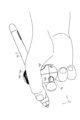
- FIG. 2 shows a state in which a user is holding the controller 6 in his/her right hand.
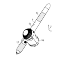
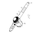
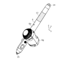
- 3A to 3C are perspective views of the controller 6 as viewed from various angles.
- 3A to 3C are perspective views of the controller 6 as viewed from various angles.
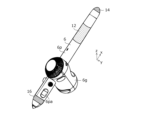
- FIG. 2 is a perspective view of a controller 6 according to the first embodiment of the present invention.
- 1A and 1B are diagrams for explaining a method of arranging a plurality of markers (at substantially uniform density) in the background art.
- 1 is a diagram for explaining a method of arranging multiple markers (at the vertices of a regular polyhedron or a geodesic dome) in the background art.
- FIG. 1 is a diagram for explaining a method of arranging multiple markers (at the vertices of a regular polyhedron or a geodesic dome) in the background art.
- FIG. 1 is a diagram for explaining a method of arranging a plurality of markers (arranged in a grid pattern) in the background art.
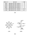
- (a) is a diagram showing a type of spiral phyllotaxis
- (b) is a diagram showing an example of 3/8 phyllotaxis.
- 1A to 1C are diagrams showing examples of specific arrangements of multiple markers in a spiral arrangement section 10.
- 1A to 1C are diagrams showing examples of specific arrangements of multiple markers in a spiral arrangement section 10.
- FIG. 13 is a perspective view of a controller 6 according to a modified example of the first embodiment of the present invention.
- FIG. 11 is a perspective view of a controller 6 according to a second embodiment of the present invention.
- FIG. 1A is a diagram showing an example in which a plurality of markers are arranged on the surface of an ellipsoid
- FIG. 1B is a diagram showing an example in which a plurality of markers are arranged on the surface of a cylinder.
- a figure showing another example of the arrangement of multiple markers in the spiral arrangement section 12 (a combination of spirals that are inverted relative to each other in the phyllotactic axis direction).
- a figure showing another example of the arrangement of multiple markers in the spiral arrangement section 12 (a spiral with varying spacing in the phyllotaxis direction).
- FIG. 13 is a perspective view of a controller 6 according to a first modified example of the second embodiment of the present invention.
- FIG. 13 is a perspective view of a controller 6 according to a second modified example of the second embodiment of the present invention.
- FIG. 13 is a perspective view of a controller 6 according to a third modified example of the second embodiment of the present invention.
- FIG. 13 is a perspective view of a controller 6 according to a fourth modified example of the second embodiment of the present invention.
- 13A and 13B are diagrams showing examples of marker arrangement in the non-helical arrangement portion 16.
- FIG. FIG. 13 is a perspective view of a controller 6 according to a fifth modified example of the second embodiment of the present invention.
- 13A to 13C are diagrams showing examples of specific arrangements of a plurality of markers on a controller 6 according to a fifth modified example of the second embodiment of the present invention.
- 13A to 13C are diagrams showing examples of specific arrangements of a plurality of markers on a controller 6 according to a fifth modified example of the second embodiment of the present invention.
- 13A to 13C are diagrams showing examples of specific arrangements of a plurality of markers on a controller 6 according to a fifth modified example of the second embodiment of the present invention.
- FIG. 1 is a diagram showing a state in which a tracking system 1 according to a first embodiment of the present invention is in use.
- the tracking system 1 is configured to have a computer 2, a position detection device 3, three cameras 4a to 4c, a head-mounted display 5, and a pen-shaped controller 6.
- the computer 2, the position detection device 3, the cameras 4a to 4c, the head-mounted display 5, and the controller 6 are each configured to be able to communicate with each other via wired or wireless communication.
- a user uses the tracking system 1 while sitting in a desk chair 101, wearing a head-mounted display 5 on his/her head, and holding a controller 6 in his/her right hand.
- An XR space rendered by a computer 2 is displayed on the display surface of the head-mounted display 5, and the user operates the controller 6 above the desk 100 while looking at this XR space.
- the controller 6 is an XR controller used within the XR space, and is used to control 3D objects displayed within the XR space (specifically, drawing 3D objects, moving 3D objects, etc.).
- the controller 6 is also formed in a pen-like shape, and is also used to perform input using the position detection device 3.
- the computer 2 is configured as a notebook personal computer placed in the center of the desk 100.
- the computer 2 does not necessarily need to be placed in the center of the desk 100, and may be placed in a position where it can communicate with the position detection device 3, the cameras 4a to 4c, the head-mounted display 5, and the controller 6.
- the computer 2 can be configured as various types of computers, such as a desktop personal computer, a tablet personal computer, a smartphone, or a server computer, in addition to a notebook personal computer.
- Computer 2 plays a role in tracking the movements of head-mounted display 5, controller 6, and position detection device 3 by periodically detecting the positions and orientations of each of these based on the images captured by cameras 4a to 4c.
- Computer 2 generates an XR space and 3D objects to be displayed therein based on the movements of each device being tracked and the operation states of each operation button and dial button (described below) provided on controller 6, and performs processing to render the generated XR space and 3D objects and transmit them to head-mounted display 5.
- Head-mounted display 5 plays a role in displaying an XR space including one or more 3D objects by displaying the rendered image transmitted from computer 2.
- the position detection device 3 is configured as a tablet placed on the top surface of the desk 100 in a position that corresponds to the front side of the computer 2 as seen from the user.
- the position detection device 3 does not necessarily have to be placed in this position, and it may be placed within reach of the user sitting in the desk chair 101.
- the position detection device 3 and the computer 2 may also be configured as an integrated device, such as a tablet terminal.
- the position detection device 3 has the function of periodically detecting the position of the pen tip of the controller 6 on the touch surface and successively transmitting the detected positions to the computer 2.
- the computer 2 generates and renders stroke data constituting a 2D object or a 3D object based on the transmitted positions.
- the specific method of position detection by the position detection device 3 is not particularly limited, but it is preferable to use, for example, an active electrostatic method or an electrostatic induction method.
- Camera 4a to 4c are imaging devices for taking still or moving images, and are configured to sequentially supply the captured images to computer 2.
- Camera 4a is positioned opposite the user across desk 100, camera 4b is above the user's left side, and camera 4c is above the user's right side, each oriented so that they can capture the top surface of desk 100.
- Cameras 4a to 4c each have a rolling shutter, and are positioned so that the sub-scanning direction of the rolling shutter coincides with the vertical direction in order to minimize distortion of controller 6 in the image.
- FIG. 2 shows a state in which a user is holding the controller 6 in his/her right hand.
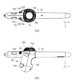
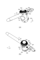
- FIGS. 3(a), 3(b), 4(a), and 4(b) are perspective views of the controller 6 viewed from various angles. Note that the actual controller 6 has a spiral arrangement section 10 shown in FIG. 5 below, but this is omitted from these drawings. Details of the spiral arrangement section 10 will be explained in more detail later with reference to FIGS. 5 to 12.
- the controller 6 is configured to have a pen-shaped pen portion 6p and a grip portion 6g fixed to the pen portion 6p so that its longitudinal direction intersects with the axial direction of the pen portion 6p.
- the axial direction of the pen portion 6p will be referred to as the x-direction
- the direction in the plane formed by the x-direction and the longitudinal direction of the grip portion 6g and perpendicular to the x-direction will be referred to as the z-direction
- the direction perpendicular to both the x-direction and the z-direction will be referred to as the y-direction.
- the surface of the pen part 6p is provided with pressure pads 6pa, 6pb and shift buttons 6pc, 6pd.
- the pressure pads 6pa, 6pb are components including a pressure sensor and a touch sensor, and are arranged symmetrically with respect to the xz plane at positions on the side of the pen part 6p near the pen tip.
- the pressure detected by the pressure sensor is used for selection or drawing in the application. Meanwhile, the information indicating the presence or absence of touch detected by the touch sensor is used to determine whether the pressure sensor output is on or off, and to realize a light double tap.
- the shift buttons 6pc, 6pd are switches assigned to the application menu, and are arranged symmetrically with respect to the xz plane between the pressure pads 6pa, 6pb and the grip part 6g. As can be seen from FIG. 2, a user holding the controller 6 with his right hand operates the pressure pad 6pa and shift button 6pc with his thumb, and the pressure pad 6pb and shift button 6pd with his index finger.
- the surface of the grip section 6g is provided with a tact top button 6ga, a grab button 6gb, tact buttons 6gc and 6gd, a dial button 6ge, and a recess 6gf.
- the tact top button 6ga is a switch that functions as a power button when pressed and held, and is disposed on the surface of the end of the grip section 6g that is closer to the pen section 6p than both ends in the longitudinal direction.
- this end will be referred to as the "upper end”
- the end of the grip section 6g that is farther from the pen section 6p than both ends in the longitudinal direction will be referred to as the "lower end”.
- the dial button 6ge is a rotatable ring-shaped member that is configured to output a rotation amount. This rotation amount is used, for example, to rotate a selected object.
- the dial button 6ge is also disposed on the upper end of the grip section 6g so as to surround the tact top button 6ga.
- the grab button 6gb is a switch used to grab and move an object, and is located near the lower end of the pen tip side of the grip part 6g.
- the tact buttons 6gc and 6gd are switches used as auxiliary buttons like the right button on a mouse, and are located near the pen part 6p when viewed in the z direction on the pen tip side of the grip part 6g.
- the tact button 6gc is located on the thumb side when the controller 6 is held in the right hand, and the tact button 6gd is located on the index finger side when the controller 6 is held in the right hand.
- a user holding the controller 6 in their right hand will press the grab button 6gb with their middle finger. Additionally, they will press the tact button 6gc with their thumb and the tact button 6gd with their index finger.
- the rotation operation of the dial button 6ge and the pressing of the tact top button 6ga are performed by the user's thumb.
- the tact top button 6ga and the dial button 6ge are located in such a way that they cannot be operated unless the user intentionally lifts their thumb to the upper end of the grip portion 6g, and therefore are exposed and not hidden by the user's hand under normal conditions.
- the recess 6gf is configured to fit exactly between the base of the index finger and the base of the thumb when the user holds the controller 6. Providing this recess 6gf on the controller 6 reduces fatigue for the user when using the controller 6.
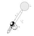
- FIG. 5 is a perspective view of the controller 6 according to this embodiment.
- the controller 6 includes a spherical portion 7 attached to the end of a pen portion 6p.
- a number of markers are arranged in a phyllotaxis on the surface of the spherical portion 7, and this number of markers constitutes a spiral arrangement portion 10. The phyllotaxis arrangement will be described in detail later with reference to FIGS. 10 to 12.
- the specific type of markers constituting the spiral arrangement section 10 is not particularly limited, but it is preferable to use infrared LEDs (Light Emitting Diodes).
- the cameras 4a to 4c are each configured as an infrared camera capable of visualizing infrared light
- the computer 2 is configured to detect the position and orientation of the controller 6 based on the arrangement of the markers that appear in the images captured by the cameras 4a to 4c.
- the arrangement of multiple markers in the spiral arrangement section 10 will be specifically described below with reference to Figures 6 to 12.
- Figs. 6 to 9 are diagrams explaining the arrangement methods of multiple markers. Below, various arrangement methods will be explained with reference to Figs. 6 to 9, and then the detailed configuration of the spiral arrangement section 10 according to this embodiment and the advantages of adopting the spiral arrangement section 10 according to this embodiment will be explained in detail with reference to Figs. 10 to 12.
- FIG. 6 is a diagram showing an example of arranging multiple markers at approximately uniform density.
- the spheres represent the spherical portions 7, and the black circles represent the individual markers.
- this example of an arrangement will be referred to as an "approximately uniform density arrangement.”
- FIGS. 6(a) to 6(c) respectively show an example of arranging multiple markers at approximately uniform density with high density, an example of arranging multiple markers at approximately uniform density with medium density, and an example of arranging multiple markers at approximately uniform density with low density.
- One method for determining the specific position of each marker in an approximately uniform density arrangement is to randomly generate multiple arrangement patterns using a sequential random method, a Poisson disk sampling method, or the like, and then determine the most suitable arrangement from among them using a method such as the Monte Carlo method.
- the computer 2 In order for the computer 2 to detect the position and orientation of the controller 6 with high accuracy, it is necessary to arrange multiple markers on the surface of the housing so that at least three markers are captured in the images captured by each of the cameras 4a to 4c with sufficient distance between them (i.e., without unevenness in placement), and so that the placement patterns (geometric features) are sufficiently different (i.e., dissimilar) depending on the shooting direction.
- this arrangement will be referred to as the "preferred arrangement.”
- Figures 7 and 8 are diagrams showing an example of placing markers at the vertices of a regular polyhedron (regular dodecahedron, regular icosahedron, etc.) or a geodesic dome (a solid body formed by increasing the number of vertices by subdividing the faces of a regular polyhedron or semi-regular polyhedron).
- a regular polyhedron regular dodecahedron, regular icosahedron, etc.
- a geodesic dome a solid body formed by increasing the number of vertices by subdividing the faces of a regular polyhedron or semi-regular polyhedron.
- FIG. 7(a) shows an example of a regular dodecahedron
- FIG. 7(b) shows an example of markers placed at positions on the surface of a sphere that correspond to each of the 20 vertices of the regular dodecahedron.
- the sphere represents the spherical portion 7
- the black circles represent the individual markers
- the arrows extending from the black circles represent the normal direction of the sphere (curved surface) at the position of the black circle.
- FIG. 9(b) FIG. 11, FIG. 15(a), FIG. 15(b), FIG. 16(a), FIG. 17(a), and FIG. 18(a), which will be described later.
- white circles and x marks have been used instead of black circles for convenience of drawing.
- FIG. 8(a) shows projections of a spherical portion 7 having 20 markers arranged at 20 vertices of a regular dodecahedron from the x direction (upper left), z direction (lower left), and y direction (lower right), and FIG. 8(b) shows an image obtained when the spherical portion 7 of FIG. 8(a) is photographed by camera 4a.
- Each view in FIG. 8(a) is a perspective view, and not only the markers located on the front side as viewed from the line of sight, but also the markers located on the back side are plotted. This is also the case in FIG. 12(a), FIG. 16(b), FIG. 17(b), and FIG. 18(b) shown later.
- FIG. 8(a) the arrangement of the markers on the front side and the arrangement of the markers on the back side match, so the result is the same as if only the markers located on the front side were drawn.
- the opening problem occurs in the polyhedron derived arrangement because the arrangement is too symmetrical.
- the projection from the z direction (lower left) and the projection from the y direction (lower right) are completely identical.
- the projection from the x direction (upper left) is also identical to the projection from the z direction (lower left) and the projection from the y direction (lower right) except that it is rotated by 90 degrees.
- the arrangement pattern (geometric features) of the markers does not differ sufficiently depending on the shooting direction, and as a result, even when looking at the image shown in Figure 8 (b), it is not possible to tell from which direction the image was taken. Therefore, it can be said that it is difficult to achieve an optimal arrangement using the polyhedron derived arrangement.
- Figure 9 shows an example of arranging multiple markers in a lattice pattern (such as a square lattice, hexagonal lattice, rectangular lattice, or diagonal lattice).
- a lattice pattern such as a square lattice, hexagonal lattice, rectangular lattice, or diagonal lattice.
- Figure 9(a) shows an example of a square lattice drawn on a sphere
- Figure 9(b) shows an example of markers arranged at some of the intersections of the square lattice shown in Figure 9(a) (i.e., the intersections of line segments that divide the latitude and longitude equally).
- planar grid derived arrangement By using a planar grid derived arrangement, it is possible to ensure that at least three markers are captured sufficiently apart (i.e., without uneven placement) in the images captured by each of the cameras 4a to 4c.
- the opening problem occurs with a planar grid derived arrangement as with a polyhedron derived arrangement. Therefore, it can be said that it is difficult to achieve an optimal placement even with a planar grid derived arrangement.
- the spiral arrangement unit 10 of this embodiment overcomes the drawbacks of the approximately uniform density arrangement, polyhedron-derived arrangement, and planar lattice-derived arrangement described above, and makes it possible to arrange multiple markers on the surface of the housing so that at least three markers are captured sufficiently apart (i.e., without unevenness in placement) in the images captured by each of the cameras 4a to 4c, and the arrangement patterns (geometric features) are sufficiently different (i.e., dissimilar) depending on the shooting direction.
- a detailed explanation will be given below with reference to Figures 10 to 12.
- phyllotaxis is the arrangement of leaves on stems in plants in nature, and includes “alternate phyllotaxis,” in which one leaf grows on each node of the stem, “opposite phyllotaxis,” in which two leaves grow on each node of the stem, and “whorl phyllotaxis,” in which three or more leaves grow on each node of the stem.
- alternate phyllotaxis those in which the leaves grow in a spiral that extends along the direction of the stem are specifically called “spiral phyllotaxis.”
- Figure 10(a) shows types of spiral phyllotaxis.
- an r/n phyllotaxis the leaf that emerges from the stem at the same angle (angle when viewed from directly above) as the first leaf is the n+1st leaf, and the leaves are attached in such a way that a spiral rotates r times around the stem between the first and n+1st leaves.
- various combinations of r and n can exist, such as 1/2 phyllotaxis, 1/3 phyllotaxis, 2/5 phyllotaxis, 3/8 phyllotaxis, 5/13 phyllotaxis, and 8/21 phyllotaxis.
- the "135 degrees” shown in the figure is the projection angle between the nth and n+1th sheets (angle when viewed from the axial direction of the spiral), and is called the "opening degree.”
- the opening degree differs depending on the type of phyllotaxis.
- 1/2 phyllotaxis it is 180 degrees, for 1/3 phyllotaxis, it is 120 degrees, for 2/5 phyllotaxis, it is 144 degrees, for 3/8 phyllotaxis, it is 135 degrees, for 5/13 phyllotaxis, it is 1800/13 ⁇ 138.5 degrees, and for 8/21 phyllotaxis, it is 2880/21 ⁇ 137.1 degrees.
- FIG. 11 and 12 are diagrams showing examples of the arrangement of multiple markers (multiple markers arranged in a phyllotaxis) in the spiral arrangement section 10.
- FIG. 11 shows an example in which 22 markers are arranged on the surface of a sphere in an 8/21 phyllotaxis.
- the multiple markers constituting the spiral arrangement section 10 are arranged so that the axis of the phyllotaxis (a line corresponding to the stem, hereinafter referred to as the "phyllotaxis axis") passes through the center of the sphere constituting the spherical section 7.
- the intervals between the markers in the phyllotaxis direction may be equal. Note that, although FIG.
- FIG. 12(a) shows projections of the spherical section 7 having multiple markers according to the example of FIG. 11 from the x-direction (upper left), z-direction (lower left), and y-direction (lower right), and
- FIG. 12(b) shows an image obtained when the spherical section 7 in FIG. 12(a) is photographed by the camera 4a.
- the configuration of the controller 6 makes it possible to arrange multiple markers on the surface of the housing so that at least three markers are captured in the images captured by each of the cameras 4a to 4c with sufficient distance between them (i.e., with no unevenness in placement), and so that the placement patterns (geometric features) are sufficiently different (i.e., dissimilar) depending on the shooting direction. Therefore, the position and orientation of the controller 6 can be detected with high accuracy using the multiple markers arranged on the surface of the housing.
- FIG. 13 is a perspective view of a controller 6 according to a modification of this embodiment.
- the controller 6 according to this modification further includes a spherical portion 8 attached to the upper end of the grip portion 6g in the controller 6 according to this embodiment.
- On the surface of the spherical portion 8, a plurality of markers (infrared LEDs) are arranged in a phyllotaxis similar to that on the surface of the spherical portion 7, and these markers constitute a spiral arrangement portion 11.
- the computer 2 is configured to detect the position and orientation of the controller 6 based on the arrangement of the markers in each of the spiral arrangement portions 10 and 11 that appear in the images captured by the cameras 4a to 4c. In this way, the computer 2 can detect the orientation of the controller 6 from the relative positional relationship of the spiral arrangement portions 10 and 11, making it possible to detect the position and orientation of the controller 6 with even higher accuracy.
- spiral arrangement portion 10 and the spiral arrangement portion 11 do not have to have exactly the same shape.
- the sizes of the spherical portion 7 and the spherical portion 8 may be different, or different types of phyllotaxis may be adopted for the spiral arrangement portion 10 and the spiral arrangement portion 11. This makes it possible to prevent the computer 2 from mistakingly detecting the spiral arrangement portion 10 and the spiral arrangement portion 11.
- the tracking system 1 according to this embodiment differs from the tracking system 1 according to the first embodiment in terms of the configuration of the controller 6. Therefore, in the following, the same reference numerals as in the first embodiment are used to designate the same parts as in the tracking system 1 according to the first embodiment, and a description thereof will be omitted, and the description will continue by focusing on the differences from the first embodiment.
- FIG. 14 is a perspective view of the controller 6 according to this embodiment. As shown in the figure, the controller 6 according to this embodiment is configured to have a spiral arrangement portion 12 on the side of the pen portion 6p, rather than a spherical portion 7 (see FIG. 5). The controller 6 according to this embodiment does not have a spherical portion 7.
- the spiral arrangement section 12 is arranged on the side of the pen section 6p that is closer to the distal end than the grip section 6g. Also, although not shown in FIG. 14, the spiral arrangement section 12 is configured with a plurality of markers that are phyllotactically arranged so that the phyllotactic axis coincides with the pen axis. As with the first embodiment, the type of marker is preferably an infrared LED.
- FIG. 15(a) is a diagram showing an example of arranging multiple markers on the surface of an ellipsoid
- FIG. 15(b) is a diagram showing an example of arranging multiple markers on the surface of a cylinder.
- 22 markers are arranged according to 8/21 phyllotaxis
- the phyllotaxis axis coincides with the major axis of the ellipsoid
- the phyllotaxis axis coincides with the axis of the cylinder.
- the spacing between the markers in the phyllotaxis direction may be equal, as in the case of arranging the markers on the surface of a sphere.
- the curved surface on which the multiple markers are phyllotaxis-arranged can be not only the surface of a sphere described in the first embodiment, but also surfaces of various shapes.
- the spiral arrangement unit 12 according to this embodiment utilizes such properties of the phyllotaxis arrangement to arrange multiple markers on the side of the pen unit 6p.
- the configuration of the controller 6 according to this embodiment also makes it possible to arrange multiple markers on the surface of the housing so that at least three markers are captured sufficiently apart (i.e., evenly spaced) in the images captured by each of the cameras 4a to 4c, and the arrangement patterns (geometric features) are sufficiently different (i.e., dissimilar) depending on the shooting direction. Therefore, the position and orientation of the controller 6 can be detected with high accuracy using the multiple markers arranged on the surface of the housing.
- the arrangement of the multiple markers in the spiral arrangement section 12 is not limited to the simple phyllotactic arrangement as shown in Figures 15(a) and 15(b). This point will be explained in detail below with reference to Figures 16 to 18.
- Figures 16 to 18 each show another example of the arrangement of multiple markers in the spiral arrangement section 12.
- Each figure (a) is a transparent perspective view of the spiral arrangement section 12, and each figure (b) shows the projection of the spiral arrangement section 12 shown in (a) from the x direction (upper left), z direction (lower left), and y direction (lower right).
- Figure 16 shows an example in which the helical arrangement section 12 is formed by two spirals each made up of a plurality of markers arranged in a phyllotaxis according to 3/8 phyllotaxis.
- a white circle indicates one spiral
- a cross indicates the other spiral.
- the other spiral is the first spiral rotated 180° around the phyllotaxis axis (around the x-axis), and the two spirals form a double helix.
- the helical arrangement section 12 according to this embodiment can also be formed by such a double helix, which can further reduce the risk of the opening problem occurring. Note that although an example of a double helix is shown in Figure 16, the helical arrangement section 12 can also be formed by a multiple helix of three or more layers.
- Figure 17 also shows an example in which the spiral arrangement section 12 is formed by two spirals each made up of a number of markers arranged in a 3/8 phyllotaxis.
- the open circle again indicates one spiral, and the cross indicates the other.
- the other spiral is the first spiral reversed in the phyllotaxis direction (x direction).
- the spiral arrangement section 12 according to this embodiment can also be formed by combining spirals that are reversed in the phyllotaxis direction in this way, which can further reduce the risk of the opening problem occurring.
- FIG. 18 shows an example in which the spiral arrangement section 12 is formed by one spiral consisting of multiple markers arranged in a 3/8 phyllotaxis.
- the distance between two adjacent markers in the phyllotaxis direction (x direction) is increased in an arithmetic progression.
- the spiral arrangement section 12 according to this embodiment can also be formed by a modified phyllotaxis arrangement in this way by changing the distance in the phyllotaxis direction, which makes it possible to further reduce the risk of the opening problem occurring.
- FIG. 18 shows an example in which the distance between two adjacent markers in the phyllotaxis direction is increased in an arithmetic progression
- the distance between two adjacent markers in the phyllotaxis direction may be changed in other ways. In one example, it may be increased in a geometric progression.
- controller 6 according to the first to fourth modified examples of this embodiment will be described with reference to Figures 19 to 23.
- FIG. 19 is a perspective view of a controller 6 according to a first modified example of this embodiment.
- the controller 6 according to this modified example is configured with a spiral arrangement section 13 provided on the side of the pen section 6p closer to the pen tip than the grip section 6g in the controller 6 according to this embodiment.
- the spiral arrangement section 13 is configured with a plurality of markers arranged in a phyllotaxis such that the phyllotaxis axis coincides with the pen axis, similar to the spiral arrangement section 12.
- the more specific arrangement of the plurality of markers in the spiral arrangement section 13 may be the same as or different from that in the spiral arrangement section 12.
- the plurality of markers may be arranged in a simple phyllotaxis arrangement in the spiral arrangement section 12, while the plurality of markers may be arranged in a phyllotaxis arrangement of an irregular spiral structure as described with reference to Figures 16 to 18 in the spiral arrangement section 13.
- the computer 2 can easily distinguish and detect the helical arrangement portion 12 and the helical arrangement portion 13 based on the arrangement of the markers of the helical arrangement portion 12 and the helical arrangement portion 13 that appear in the images captured by the cameras 4a to 4c.
- FIG. 20 is a perspective view of a controller 6 according to a second modified example of this embodiment.
- the controller 6 according to this modified example is configured by further including a non-helical arrangement portion 14 arranged at the end of the pen portion 6p in the controller 6 according to this embodiment.
- the non-helical arrangement portion 14 is configured with one or more markers arranged without following a phyllotactic arrangement.
- FIG. 21 is a perspective view of a controller 6 according to a third modified example of this embodiment.
- the controller 6 according to this modified example is configured by further including a non-helical arrangement portion 15 arranged at the pen tip in the controller 6 according to the third modified example of this embodiment.
- the non-helical arrangement portion 15 is configured by having one or more markers arranged without following a phyllotactic arrangement, similar to the non-helical arrangement portion 14.
- FIG. 22 is a perspective view of a controller 6 according to a fourth modification of this embodiment.
- the controller 6 according to this modification further includes a non-helical arrangement portion 16 provided on the side surface of the pen part 6p closer to the pen tip than the grip part 6g.
- the helical arrangement portion 13 is provided on the side surface of the pen part 6p closer to the pen tip than the grip part 6g.
- the installation space for the pressure pads 6pa, 6pb is eroded by the helical arrangement portion 13.
- the non-helical arrangement portion 16 can be installed without a large space like the helical arrangement portion 13, so it is possible to avoid such erosion and install the pressure pads 6pa, 6pb.
- FIG. 23(a) and (b) are diagrams showing examples of marker placement in the non-helical placement section 16.
- markers black circles
- yz section section perpendicular to the pen axis
- markers black circles are placed at three of the five vertices (vertices A, C, and D when the vertices are called A to E clockwise) of a regular pentagon placed in the yz section (section perpendicular to the pen axis) of the circular pen section 6p. This placement can reduce the possibility of the opening problem occurring even when the helical placement section 12 is not photographed and only the non-helical placement section 16 is photographed.
- FIG. 24 is a perspective view of a controller 6 according to a fifth modified example of this embodiment.
- the controller 6 according to this modified example further reduces the risk of the opening problem occurring by using the non-helical arrangement section 14 in addition to the helical arrangement section 12 and non-helical arrangement section 16 in the controller 6 according to the fourth modified example of this embodiment, and therefore the computer 2 can detect the position and orientation of the controller 6 with higher accuracy than when only the helical arrangement section 12 and non-helical arrangement section 16 are used.
- FIGS. 25 to 27 are diagrams showing examples of specific arrangements of multiple markers on a controller 6 according to a fifth modified example of this embodiment.
- Each of FIGS. 25(a) to 25(d) and 26(a) to 26(d) shows a side view of the controller 6 obtained when the viewpoint is rotated around the x direction (the axial direction of the pen portion 6p) at the angle shown.
- FIG. 27(a) shows a side view of the controller 6 as seen from the tip of the pen
- FIG. 27(b) shows a side view of the controller 6 as seen from the end of the pen.
- FIGS. 25 to 27 show an example in which a spiral arrangement section 12 is formed by the arrangement of multiple markers shown in FIG. 17, and a non-spiral arrangement section 16 is formed by the arrangement of multiple markers shown in FIG. 23(b).
- Figs. 25 to 27 dashed circles are drawn where the markers are located to make the position of each marker easier to understand. Furthermore, for the spiral arrangement section 12, the serial numbers 1 to 8 of the eight markers that make up one spiral are shown in dashed circles, and the serial numbers A to H of the eight markers that make up the other spiral are shown in dashed circles. As can be seen from the serial numbers, the example shown in Figs. 25 to 27 realizes the arrangement of multiple markers shown in Fig. 17 (one spiral consisting of eight markers arranged in a 3/8 phyllotaxis, and the other spiral formed by flipping the one spiral in the phyllotaxis axis direction (x direction)).
- the phyllotactic arrangement of the irregular spiral structure (double or multiple spirals, a combination of spirals inverted in the phyllotactic axis direction, or a spiral with varying spacing in the phyllotactic axis direction) described with reference to Figures 16 to 18 may be applied to the spiral arrangement units 10 and 11 described in the first embodiment.
- the spiral arrangement units 10 and 11 described in the first embodiment and the spiral arrangement units 12 and 13 and the non-spiral arrangement units 14 to 16 described in the second embodiment may be appropriately combined to configure one controller 6.
- the controller 6 shown in FIG. 13 may be combined with the spiral arrangement units 12 and 13 and the non-spiral arrangement unit 15, or the spiral arrangement unit 12 and the non-spiral arrangement units 15 and 16.
- one controller 6 may be configured by appropriately selecting a part of the spiral arrangement units 10 and 11 described in the first embodiment and the spiral arrangement units 12 and 13 and the non-spiral arrangement units 14 to 16 described in the second embodiment.
- the controller 6 may be configured to have the spiral arrangement unit 11 without the spiral arrangement unit 10, and to have the spiral arrangement unit 13 and the non-spiral arrangement units 14 to 16 without the spiral arrangement unit 12.
- Tracking system 2 Computer 3 Position detection device 4a to 4c Camera 5 Head mounted display 6 Controller 6g Grip section 6ga Tact top button 6gb Grab button 6gc, 6gd Tact button 6ge Dial button 6gf Recess 6p Pen section 6pa, 6pb Pressure pad 6pc, 6pd Shift button 7, 8 Spherical section 10 to 13 Spiral arrangement section 14 to 16 Non-spiral arrangement section 100 Desk 101 Desk chair
Landscapes
- Engineering & Computer Science (AREA)
- General Engineering & Computer Science (AREA)
- Theoretical Computer Science (AREA)
- Human Computer Interaction (AREA)
- Physics & Mathematics (AREA)
- General Physics & Mathematics (AREA)
- Length Measuring Devices By Optical Means (AREA)
- Position Input By Displaying (AREA)
- Image Processing (AREA)
Priority Applications (4)
| Application Number | Priority Date | Filing Date | Title |
|---|---|---|---|
| JP2025515041A JPWO2024219004A1 (cg-RX-API-DMAC7.html) | 2023-04-18 | 2023-12-06 | |
| KR1020257031109A KR20250170033A (ko) | 2023-04-18 | 2023-12-06 | Xr 컨트롤러 |
| CN202380093622.0A CN120604199A (zh) | 2023-04-18 | 2023-12-06 | Xr控制器 |
| US19/359,409 US20260037077A1 (en) | 2023-04-18 | 2025-10-15 | Xr controller |
Applications Claiming Priority (4)
| Application Number | Priority Date | Filing Date | Title |
|---|---|---|---|
| JP2023067725 | 2023-04-18 | ||
| JP2023-067725 | 2023-04-18 | ||
| JP2023-196243 | 2023-11-17 | ||
| JP2023196243 | 2023-11-17 |
Related Child Applications (1)
| Application Number | Title | Priority Date | Filing Date |
|---|---|---|---|
| US19/359,409 Continuation US20260037077A1 (en) | 2023-04-18 | 2025-10-15 | Xr controller |
Publications (1)
| Publication Number | Publication Date |
|---|---|
| WO2024219004A1 true WO2024219004A1 (ja) | 2024-10-24 |
Family
ID=93152235
Family Applications (1)
| Application Number | Title | Priority Date | Filing Date |
|---|---|---|---|
| PCT/JP2023/043616 Ceased WO2024219004A1 (ja) | 2023-04-18 | 2023-12-06 | Xrコントローラ |
Country Status (6)
| Country | Link |
|---|---|
| US (1) | US20260037077A1 (cg-RX-API-DMAC7.html) |
| JP (1) | JPWO2024219004A1 (cg-RX-API-DMAC7.html) |
| KR (1) | KR20250170033A (cg-RX-API-DMAC7.html) |
| CN (1) | CN120604199A (cg-RX-API-DMAC7.html) |
| TW (1) | TW202443352A (cg-RX-API-DMAC7.html) |
| WO (1) | WO2024219004A1 (cg-RX-API-DMAC7.html) |
Citations (2)
| Publication number | Priority date | Publication date | Assignee | Title |
|---|---|---|---|---|
| CN212112405U (zh) * | 2020-05-12 | 2020-12-08 | 深圳市欢创科技有限公司 | 一种虚拟现实手持设备 |
| US20220350397A1 (en) * | 2021-05-03 | 2022-11-03 | Htc Corporation | Handheld electronic device |
Family Cites Families (4)
| Publication number | Priority date | Publication date | Assignee | Title |
|---|---|---|---|---|
| US9103567B2 (en) * | 2011-04-14 | 2015-08-11 | Sequence Design Ltd. | Photovoltaic array utilizing phyllotaxic architecture |
| CN111837096A (zh) * | 2018-03-23 | 2020-10-27 | 株式会社和冠 | 三维位置指示器及三维位置检测系统 |
| US10942585B2 (en) * | 2019-07-22 | 2021-03-09 | Zspace, Inc. | Trackability enhancement of a passive stylus |
| JP7760222B2 (ja) | 2021-03-22 | 2025-10-27 | 株式会社ワコム | コントローラ及びトラッキングシステム |
-
2023
- 2023-12-06 KR KR1020257031109A patent/KR20250170033A/ko active Pending
- 2023-12-06 WO PCT/JP2023/043616 patent/WO2024219004A1/ja not_active Ceased
- 2023-12-06 CN CN202380093622.0A patent/CN120604199A/zh active Pending
- 2023-12-06 JP JP2025515041A patent/JPWO2024219004A1/ja active Pending
- 2023-12-15 TW TW112148938A patent/TW202443352A/zh unknown
-
2025
- 2025-10-15 US US19/359,409 patent/US20260037077A1/en active Pending
Patent Citations (2)
| Publication number | Priority date | Publication date | Assignee | Title |
|---|---|---|---|---|
| CN212112405U (zh) * | 2020-05-12 | 2020-12-08 | 深圳市欢创科技有限公司 | 一种虚拟现实手持设备 |
| US20220350397A1 (en) * | 2021-05-03 | 2022-11-03 | Htc Corporation | Handheld electronic device |
Also Published As
| Publication number | Publication date |
|---|---|
| US20260037077A1 (en) | 2026-02-05 |
| JPWO2024219004A1 (cg-RX-API-DMAC7.html) | 2024-10-24 |
| KR20250170033A (ko) | 2025-12-04 |
| CN120604199A (zh) | 2025-09-05 |
| TW202443352A (zh) | 2024-11-01 |
Similar Documents
| Publication | Publication Date | Title |
|---|---|---|
| CN110794958B (zh) | 在增强/虚拟现实环境中使用的输入设备 | |
| Yan et al. | Eyes-free target acquisition in interaction space around the body for virtual reality | |
| US9830444B2 (en) | Password processing device | |
| WO2024226681A1 (en) | Methods for displaying and rearranging objects in an environment | |
| EP2594895B1 (en) | Object position and orientation detection system | |
| EP3438790B1 (en) | Input device and image display system | |
| GB2388418A (en) | Input or pointing device with a camera | |
| US20120068927A1 (en) | Computer input device enabling three degrees of freedom and related input and feedback methods | |
| US9218062B2 (en) | Three-dimensional menu system using manual operation tools | |
| CN110140100B (zh) | 三维增强现实对象用户界面功能 | |
| CN121285789A (zh) | 用于在与三维环境交互时选择性地访问计算机系统的系统功能并调整计算机系统的设置的设备、方法和图形用户界面 | |
| US20260079587A1 (en) | Controller and tracking system | |
| US20200346103A1 (en) | Tracking three dimensional puzzle components using embedded image sensors and contactless absolute position encoders | |
| WO2005052778A1 (ja) | 情報入力器、収納装置、情報入力装置、及び情報処理装置 | |
| US20260037077A1 (en) | Xr controller | |
| US11099658B2 (en) | Determining orientation of a trackball | |
| Wieland et al. | Investigating the Potential of Haptic Props for 3D Object Manipulation in Handheld AR | |
| Ullah et al. | Leveraging Head Movement for Navigating Off-Screen Content on Large Curved Displays | |
| Han | Evaluating the Effects of 3D User Interactions and Virtual Displays on Human Cognition and Perception for Immersive Analytics | |
| US20240074816A1 (en) | Sterilizable image manipulation device | |
| Havig et al. | Evaluation of tangible user interfaces for command and control in virtual environments | |
| Teather | Comparing 2D and 3D direct manipulation interfaces | |
| Ren | Designing for Effective Freehand Gestural Interaction | |
| JP5439348B2 (ja) | 操作情報入力システムとその操作情報処理装置 | |
| HK40011262A (en) | Three-dimensional augmented reality object user interface functions |
Legal Events
| Date | Code | Title | Description |
|---|---|---|---|
| 121 | Ep: the epo has been informed by wipo that ep was designated in this application |
Ref document number: 23934145 Country of ref document: EP Kind code of ref document: A1 |
|
| ENP | Entry into the national phase |
Ref document number: 2025515041 Country of ref document: JP Kind code of ref document: A |
|
| WWE | Wipo information: entry into national phase |
Ref document number: 2025515041 Country of ref document: JP |
|
| WWE | Wipo information: entry into national phase |
Ref document number: 202380093622.0 Country of ref document: CN |
|
| WWP | Wipo information: published in national office |
Ref document number: 202380093622.0 Country of ref document: CN |
|
| ENP | Entry into the national phase |
Ref document number: 1020257031109 Country of ref document: KR Free format text: ST27 STATUS EVENT CODE: A-0-1-A10-A15-NAP-PA0105 (AS PROVIDED BY THE NATIONAL OFFICE) |
|
| NENP | Non-entry into the national phase |
Ref country code: DE |
|
| 122 | Ep: pct application non-entry in european phase |
Ref document number: 23934145 Country of ref document: EP Kind code of ref document: A1 |